Download - ESLON - mmpkorea.com

SCH80 PVC & CPVC Piping SystemsSpecifications & Engineering Manual
ESLON
11. 2016 3rd Edition
Copyright 2008SEKISUI CHEMICAL CO., LTD.May not be copied in whole or part.
Revision No.1, Jan. 2008
2016. 11. 3TH TXNo. 06270
Printed November.2016.3rd EditionESLON SCH80 PVC & CPVC Piping SystemsSpecifications & Engineering ManualSEKISUI CHEMICAL CO.,LTD.Industrial Piping System Division
http://www.eslon-plant.jp E-mail: [email protected]
Industrial Piping System Division
SEKISUI CHEMICAL CO.,LTD.2-3-17 Toranomon Minatoku,Tokyo,105-8450 JapanTEL +81-3-5521-0555 FAX +81-3-5521-0753
SEKISUI INDUSTRIAL PIPING CO., LTD.No.18, Jing 1st Rd.,Chung Kang Export Processing Zone, Wuqi Dist., Taichung City 43541, Taiwan, R.O.C.TEL +886-4-2657-3688 FAX +886-4-2657-9638
SEKISUI (SHANGHAI) INTERNATIONAL TRADING CO., LTD.Room 702-707, Metro Tower, No.30, Tianyaoqiao Road Shanghai. 200030, ChinaTEL +86-21-6482-0638 FAX +86-21-6482-0639
SEKISUI CHEMICAL SINGAPORE (PTE.) LTD.2 Jurong East Street Road 21,#05-17,IMM Building,Singapore 609601TEL +65-6562-5081 FAX +65-6562-5021
SEKISUI CHEMICAL G.m.b.H.Cantadorstr.3 40211 Dusseldorf, GermanyTEL +49-211-36977-0 FAX +49-211-36977-31
SEKISUI VIETNAM CO.,LTDRoom1414, CornerStone Building, 16Phan Chu Trinh St, Hoan Kiem District, Hanoi, VietnamTEL +84-4-3939-2677 FAX +84-4-3939-2678

Best Quality from Sekisui to the World
Sekisui Chemical is the leading company of plastic pipes in the world.The brand of our plastic pipe is “Eslon”, which is well-known as high quality all over the world.Since 1953, Eslon pipe was first on the market, Sekisui Chemical has been providing a variety of plastic pipes.Sekisui Chemical is the unique company in the various fields, who has the techniques of materials such as PVC polymerization, formulation, and CPVC denaturation of PVC resin, and the techniques of production, special long term evaluation, piping design and installation.Our excellent technique has a high reputation not only in Japan, but also in the world.Sekisui Chemical is proud of providing Schedule80 PVC & CPVC pipes and fittings for the world based on the best quality.

TABLE OF CONTENTS
1. Advatages of Eslon Sch80 PVC and CPVC Pipe .................................................... 4
2. Eslon Sch80 PVC and CPVC Pipe and Fittings ....................................................... 81 Physical Properties of PVC and CPVC Material ........................................................................ 9
2 Schedule80 Pipe ...................................................................................................................... 11
3 Schedule80 Fittings .................................................................................................................. 12
4 True Union ................................................................................................................................ 26
5 Flange ...................................................................................................................................... 27
6 Gasket ...................................................................................................................................... 30
3. Installation ................................................................................................................... 32
1 Storage and Handling ............................................................................................................... 33
2 General Recommendations ..................................................................................................... 35
3 Rules and Guidelines ............................................................................................................... 36
4. Safety Precautions ..................................................................................................... 44
NOTE: Some of the information contained herein is generated by independent sources. Such information is accurate to the best of SEKISUIs' knowledge, but SEKISUI disclaims any liability for the accuracy or completeness of such information or the reliance by any party on such information.
ESLON QUALITY POLICYIt is the policy of all operations of Eslon to continuously strive to meet the requirements of our customers by offering products and services which are of the highest quality. This re-quires that we obtain thorough leadership in quality or product, quality of service, and quality of delivery, by providing a work environment which nurtures the growth and involvement of all employees. We will maintain the most effective quality system to enable us to best meet our customers’ needs.
Copyright 2008 SEKISUI CHEMICAL CO., LTD.May not be copied in whole or part. Revision No.1, Jan. 2008

Understanding Safety Alert Messages There are several types of safety-alert messages which appear throughout this Technical Manual. Famil-
iarize yourself with these types of messages and the importance of the various signal words, as explained
below.
This safety alert symbol indicates important safety messages in this manual.
When you see this symbol be alert to the possibility of personal injury and carefully read and fully un-
derstand the message that follows.
DANGER: Indicates an imminently hazardous situation which, if not avoided, will result in death or serious
injury. Safety Signs identified by the signal word DANGER should be used sparingly and only for those
situations presenting the most serious hazards.
WARNING: Indicates a potentially hazardous situation which, if not avoided, will result in death or serious
injury. Hazards identified by the signal word WARNING present a lesser degree of risk of injury or death
than those identified by the signal word DANGER.
CAUTION: Indicates a potentially hazardous situation which, if not avoided, may result in minor or moder-
ate injury.
!DANGER!
WARNING!
CAUTION!
1Advatages of Eslon Sch80 PVC
and CPVC Pipe

Adv
anta
ges
of E
slon
Sch8
0 PV
C a
nd C
PVC
Pip
e
Advatages of Eslon Sch80PVC and CPVC Pipe
Sekisui Eslon PVC and CPVC pipe have a num-
ber of outstanding features, such as high chemi-
cal resistance, easy installation, and reasonable
price, which can lead to the reduction of total
construction cost. Eslon PVC and CPVC can or
should replace other materials of construction in
size ranges available for all sorts of piping sys-
tems.
CPVC (Chlorinated Polyvinyl Chloride) is another
rigid pipe which has three highly-desirable char-
acteristics, good mechanical strength at high
temperatures and higher chemical resistance
and relatively compared to metal. CPVC polymer
is more chlorinated into PVC polymer. This extra
chlorine is responsible for the material’s high-tem-
perature strength and other properties which are
valuable for industrial piping. For pressure piping
applications, it is recommended for temperatures
as high as 200°F compared with 140°F of PVC.
Eslon Sch80 PVC & CPVC Pipe ranging in sizes
from 1/2” through 24”, and PVC fittings and PVC
valves are available for light, medium, and heavy
duty use.
PVC and CPVC are environmentally friendly poly-
mer in terms of low carbonic acid gas emission in
manufacturing process
AdvantagesChemical Resistance PVC and CPVC pipe are inert to attack by strong
acids, alkalis, salt solutions, alcohols, and many
other chemicals. They are dependable on corro-
sive applications and impart no tastes or
odors to materials carried in them. They do not
react with materials carried, nor act as a catalyst.
All possibility of contamination, or chemical pro-
cess changes, and all danger of clouding, slug-
ging, or discoloration are eliminated.
Strength
PVC and CPVC pipe are highly resilient, tough
and durable products that have high tensile and
high impact strength. They will withstand surpris-
ingly high pressure for long periods.
Fire Resistance PVC and CPVC pipe products
are self extinguishing and will not support com-
bustion. They have an ASTM E-84 flame spread
rate of 25 or less.
Internal Corrosion Resistance PVC and CPVC pipe resist chemical attack by
most acids, alkalis, salts, and organic media such
as alcohols and aliphatic hydrocarbons, within
certain limits of temperature and pressure. They
provide the needed chemical resistance, while
eliminating the disadvantages of special metals,
lined piping, glass, wood, ceramics, or other spe-
cial corrosion-resisting materials, which formerly
had to be used.
5

SCH80 PVC & CPVC Piping SysyemsESLON
Advantages of Eslon Sch80 PVC
and CPVC
Pipe
External Corrosion Resistance Industrial fumes, humidity, saltwater, weather, at-
mospheric, or underground conditions, regard-
less of type of soil or moisture encountered, can-
not harm rigid PVC and CPVC plastic pipe.
Scratches or surface abrasions do not provide
points which corrosive elements can attack.
Immunity to Galvanic or Electrolytic Attack PVC
and CPVC pipe are inherently immune to galvanic
or electrolytic action. They can be used under-
ground, underwater, in the presence of metals,
and can also be connected to metals.
Freedom from Toxicity, Odors, Tastes PVC and CPVC piping are non-toxic, odorless,
and tasteless. They have been listed by the Na-
tional Sanitation Foundation for use with potable
water.
Corrosion Free With many other pipe materials, slight corrosion
may occur. The corroded particles can contami-
nate the piped fluid, complicating further process-
ing, or causing bad taste, odors, or discoloration.
This is particularly undesirable when the piped
fluid is for domestic consumption. With PVC and
CPVC, there are no corrosive by-products, there-
fore, no contamination of the piped fluid.
Low Friction Loss The smooth interior surfaces of PVC and CPVC
pipe, compared to metal and other piping materi-
als, assure low friction loss and high flow rates.
Additionally, since PVC and CPVC pipe
will not rust, pit, scale, or corrode, the high flow
rates will be maintained for the life of the piping
system.
Low Thermal Conductivity PVC and CPVC pipe have a much lower ther-
mal conductivity factor than metal pipe. There-
fore, fluids being piped maintain a more constant
temperature. In most cases, pipe insulation is not
required.
Easy Installation and Low Installation CostPVC and CPVC pipe are lightweight, convenient
to handle, relatively flexible, and easy to install.
For example, it is approximately 1/5 to 1/6 for the
weight of metal.
They have smooth, seamless interior walls. No
special tools are required for cutting. They can be
installed using solvent cementing, threading,
flanging techniques.
These features lead to lower installed costs than
conventional metal piping.
Maintenance Free Once a PVC or CPVC piping system is properly
selected, designed, and installed, it is virtually
maintenance free. It will not rust, scale, pit, cor-
rode, or promote build-up on the interior. There-
fore, years of trouble-free service can be expect-
ed when using Eslon PVC and CPVC pipe.
Standard Approved Sekisui Eslon PVC and CPVC pipe complies with
the industry standards and requirements as set
forth by the American Society for Testing and
Materials (ASTM) and the National Sanitation
Foundation (NSF International).
6

Eslon Sch80 PVC & CPVC Piping System

2Eslon Sch80 PVC and CPVC
Pipe and Fittings
1 Physical Properties of PVC and CPVC Material ............ 9
2 Schedule80 Pipe ...................................................... 11
3 Schedule80 Fittings .................................................. 12
4 True Union .................................................................. 26
5 Flange ........................................................................ 27
6 Gasket ........................................................................ 30

Eslo
n Sc
h80
PVC
and
CPV
C P
ipe
and
Fitti
ngs
1Physical Properties ofPVC and CPVC Material
Properties of PVC & CPVC PIPE
ITEM Test MethodSI unit
unit PVC CPVC
GENERAL
Cell Classification ASTM D1784 — 12454 23447
Maximum Usable Temp. — °C 60 93
Specific Gravity @ 73°F(23°C) ASTM D792 g/cc 1.42±0.02 1.55±0.02
Water Absorption % increase 24 hrs@ 73°F(23°C) ASTM D570 % 0.04 0.04
Hardness, Rockwell ASTM D785 — 110 - 120 115-125
Poisson’s Ratio @ 73°F(23°C) ASTM D638 — 0.38 0.36
MECHANICAL
Tensile Strength @ 73°F(23°C) ASTM D638 MPa 49.9 53.1
Tensile Strength @194 °F(90°C) 〃 MPa — 22.1
Tensile Modulus of Elasticity @ 73°F(23°C) 〃 GPa 2.83 2.62
Tensile Modulus of Elasticity @ 194°F(90°C) 〃 GPa — 1.52
Flexural Strength @ 73°F(23°C) ASTM D790 MPa 96.5 89.6
Flexural Modulus of Elasticity @ 73°F(23°C) 〃 GPa 2.76 2.69
Compressive Strength @ 73°F(23°C) ε =10% ASTM D695 MPa 69.0 96.5
Compressive Modulus of Elasticity @ 73°F(23°C) 〃 GPa 0.76 1.00
Izod Impact, notched @ 73°F(23°C) ASTM D256 J/m 80 160
THERMAL
Coefficient of Linear Expansion ASTM D696 m/m/°C 6.0-8.0x10 -5 7.0-8.0x10 -5
Coefficient of Thermal Conductivity ASTM C177 Watt/m/°K 0.17 0.13
Heat Deflection Temperature Under Load (264psi, annealed) ASTM D648 °C 74 110
Specific Heat ASTM D2766 J/°K/g 1.1 1.1
ELECTRICAL
Volume Resistivity ASTM D257 ohm/cm >1.0 x 10 15 >1.0 x 10 15
Dielectric Strength ASTM D149 volt/mm >1000 >1000
Dielectric Constant ASTM D150 — 3 3
Power Factor 〃 — 0.01-0.02 0.01-0.02
Electrical Conductivity — — Non Conductor Non Conductor
FIRE PERFORMANCE
Flammability Rating UL-94 — V-0 V-0, 5VB, 5VA
Flame Spread Index 〃 — <10 <10
Average Time of Burning ASTM D635 sec <5 <5
Average Extent of Burning 〃 mm <10 <10
Burning Rate 〃 mm/min Self Extinguishing Self Extinguishing
Limiting Oxygen Index (LOI) ASTM D2863 LOI 45 60
9

SCH80 PVC & CPVC Piping SysyemsESLON
Eslon Sch80 PVC and C
PVC Pipe and Fittings
Properties of PVC & CPVC PIPE Fitting
ITEM Test MethodSI unit
unit PVC CPVC
GENERAL
Cell Classification ASTM D1784 12454 23447
Maximum Usable Temp. °C 60 93
Specific Gravity @ 73°F (23°C) ASTM D792 g/cc 1.42±0.02 1.55±0.02
Water Absorption % increase 24 hrs@ 73°F (23°C) ASTM D570 % 0.04 0.04
Hardness, Rockwell ASTM D785 110 - 120 115-125
Poisson's Ratio @ 73°F (23°C) ASTM D638 0.38 0.36
MECHANICAL
Tensile Strength @ 73°F (23°C) ASTM D638 MPa 49.9 51.0
Tensile Strength @194 °F (90°C) MPa 20.7
Tensile Modulus of Elasticity @ 73°F (23°C) GPa 2.90 2.62
Tensile Modulus of Elasticity @ 194°F (90°C) GPa 1.38
Flexural Strength @ 73°F (23°C) ASTM D790 MPa 89.6 82.7
Flexural Modulus of Elasticity @ 73°F (23°C) GPa 2.90 2.76
Compressive Strength @ 73°F (23°C) ε =10% ASTM D695 MPa 69.0 103.4
Compressive Modulus of Elasticity @ 73°F(23°C) GPa 0.76 1.10
Izod Impact, notched @ 73°F (23°C) ASTM D256 J/m 66 162
THERMAL
Coefficient of Linear Expansion ASTM D696 m/m/°C 6.0-8.0x10 -5 7.0-8.0x10 -5
Coefficient of Thermal Conductivity ASTM C177 Watt/m/°K 0.16 0.13
Heat Deflection Temperature Under Load (264psi, annealed) ASTM D648 °C 80 102
Specific Heat ASTM D2766 J/°K/g 1.1 1.1
ELECTRICAL
Volume Resistivity ASTM D257 ohm/cm >1.0 x 10 15 >1.0 x 10 15
Dielectric Strength ASTM D149 volt/mm >1000 >1000
Dielectric Constant ASTM D150 3 3
Power Factor 〃 0.01-0.02 0.01-0.02
Electrical Conductivity Non Conductor Non Conductor
FIRE PERFORMANCE
Flammability Rating UL-94 V-0 V-0, 5VB, 5VA
Flame Spread Index 〃 <10 <10
Average Time of Burning ASTM D635 sec <5 <5
Average Extent of Burning mm <10 <10
Burning Rate mm/min Self Extinguishing Self Extinguishing
Limiting Oxygen Index (LOI) ASTM D2863 LOI 45 60
10

Eslo
n Sc
h80
PVC
and
CPV
C P
ipe
and
Fitti
ngs
2 Schedule80 Pipe
Schedule 80 PVC and CPVC Pipe Dimensions, Weights and Maximum Operating Pressure
Nominal Pipe Size
Outside Diameter
Wall Thickness
Approx.Inside
Diameter
Nominal Weight Max. operatingPressure PVC CPVC
inch mm mm mm mm kg/m kg/m MPa
1/2” 15 21.34 ±0.10 3.73 +0.51 13.4 0.311 0.337 5.86
3/4” 20 26.67 ±0.10 3.91 +0.51 18.3 0.421 0.457 4.76
1” 25 33.40 ±0.13 4.55 +0.53 23.8 0.618 0.670 4.34
1-1/4” 32 42.16 ±0.13 4.85 +0.58 31.9 0.855 0.927 3.59
1-1/2” 40 48.26 ±0.15 5.08 +0.61 37.5 1.037 1.124 3.24
2” 50 60.32 ±0.15 5.54 +0.66 48.6 1.435 1.556 2.76
2-1/2” 65 73.02 ±0.18 7.01 +0.84 58.2 2.190 2.373 2.90
3” 80 88.90 ±0.20 7.62 +0.91 72.8 2.932 3.178 2.55
4” 100 114.30 ±0.23 8.56 +1.02 96.2 4.288 4.648 2.21
5” 125 141.30 ±0.25 9.53 +1.14 121.1 5.950 6.450 2.00
6” 150 168.28 ±0.28 10.97 +1.32 145.0 8.186 8.873 1.93
8” 200 219.08 ±0.38 12.70 +1.52 192.2 12.433 13.477 1.72
10” 250 273.05 ±0.38 15.06 +1.80 241.1 18.436 19.983 1.59
12” 300 323.85 ±0.38 17.45 +2.08 286.9 25.365 27.493 1.59
14” 350 355.60 ±0.38 19.05 +2.29 315.2 30.430 32.983 1.52
16” 400 406.40 ±0.48 21.41 +2.57 361.0 39.125 42.408 1.52
18” 450 457.20 ±0.48 23.80 +2.84 406.8 48.943 53.050 1.52
20” 500 508.00 ±0.58 26.19 +3.15 452.5 59.596 64.922 1.52
24” 600 609.60 ±0.79 30.94 +3.71 544.0 84.974 92.105 1.45
Eslon Pipe is Manufactured to The Following Standard Specifications
Type Material(Cell Classification) Dimensions Commercial
Classification
PVC Schedule 80 ASTM D-1784(12454) ASTM D-1785 Type Ⅰ,Grade 1, PVC 1120
CPVC Schedule 80 ASTM D-1784(23447) ASTM F-441 Type Ⅳ ,Grade 1, CPVC 4120
*ASTM F480 Well Casing
NOTE: Maximum Operating Pressure is applied to 23°C
Eslon pipe and fittings are approved by NSF International 14 and 61.
NSF standard 14 : Plastics Piping System Components and Related Materials
NSF standard 61 : Drinking Water System Components - Health Effects
11
SCH80 PVC & CPVC Piping SysyemsESLON
Schedule80 Fittings3
Eslon Sch80 PVC and C
PVC Pipe and Fittings
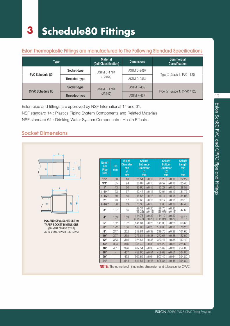
Socket Dimensions
Nomi-nal
PipeSize
ODmm
InsideDiameter
mind
mm
SocketEntranceDiameter
d1mm
SocketBottom
Diameterd2
mm
SocketLength
minl
mm1/2” 30 18 21.54 ±0.10 21.23 ±0.10 22.22 3/4” 35 24 26.87 ±0.10 26.57 ±0.10 25.40 1” 43 30 33.65 ±0.13 33.27 ±0.13 28.58
1-1/4” 53 37 42.42 ±0.13 42.04 ±0.13 31.75 1-1/2” 60 45 48.56 ±0.15 48.11 ±0.15 34.93
2” 73 57 60.63 ±0.15 60.17 ±0.15 38.10 2-1/2” 88 69 73.38 ±0.18 72.85 ±0.18 44.45
3” 107 85 89.31(89.28)
±0.20(±0.18)
88.70(88.67)
±0.20(±0.18) 47.63
4” 133 109 114.76(114.73)
±0.23(±0.20)
114.10(114.04)
±0.23(±0.20) 57.15
5” 162 132 141.81 ±0.25 141.00 ±0.25 66.686” 192 156 168.83 ±0.28 168.00 ±0.28 76.208” 247 202 219.84 ±0.38 218.70 ±0.38 101.60
10” 307 265 273.81 ±0.38 272.67 ±0.38 127.0012” 363 315 324.61 ±0.38 323.47 ±0.38 152.4014” 394 346 356.49 ±0.38 355.22 ±0.38 228.6016” 451 396 407.54 ±0.38 405.89 ±0.38 254.00 18" - 407 458.60 ±0.51 456.69 ±0.51 304.80 20" - 453 509.65 ±0.64 507.49 ±0.64 304.80 24" - 544 611.51 ±0.46 608.84 ±0.46 304.80
PVC AND CPVC SCHEDULE 80TAPER SOCKET DIMENSIONS
(SOLVENT CEMENT STYLE)ASTM D-2467 (PVC) F-439 (CPVC)
l
d1
d2d
d d2
OD
l
d1
Eslon Thermoplastic Fittings are manufactured to The Following Standard Specifications
TypeMaterial
(Cell Classification)Dimensions
CommercialClassification
PVC Schedule 80 Socket-type ASTM D-1784
(12454)
ASTM D-2467Type Ⅰ,Grade 1, PVC 1120
Threaded-type ASTM D-2464
CPVC Schedule 80Socket-type ASTM D-1784
(23447)
ASTM F-439Type Ⅳ ,Grade 1, CPVC 4120
Threaded-type ASTM F-437
Eslon pipe and fittings are approved by NSF International 14 and 61.
NSF standard 14 : Plastics Piping System Components and Related Materials
NSF standard 61 : Drinking Water System Components - Health Effects
NOTE: The numeric of ( ) indicates dimension and tolerance for CPVC.
12

Eslo
n Sc
h80
PVC
and
CPV
C P
ipe
and
Fitti
ngs
3 Schedule80 Fittings
Thread Dimensions
NominalPipeSize
Pipe
ODmm
Female ThreadMin. Length
Tmm
Male ThreadMin. Length
Smm
Overall Pipe Thread Length
Lmm
ThreadsPer In.
Nper inch
Pitch ofThread
Pmm
Height ofThread
hmm
1/2” 32.5 16.26 13.46 19.85 14.0 1.814 1.451
3/4” 38.2 16.51 13.92 20.15 14.0 1.814 1.451
1” 46.0 20.57 17.27 25.01 11.5 2.209 1.767
1-1/4” 56.0 21.59 18.03 25.62 11.5 2.209 1.767
1-1/2” 63.5 21.59 18.29 26.04 11.5 2.209 1.767
2” 77.0 22.86 19.30 26.88 11.5 2.209 1.767
2-1/2” 91.0 30.25 28.96 39.91 8.0 3.175 2.540
3” 107.0 33.02 30.48 41.50 8.0 3.175 2.540
4” 138.0 35.05 33.02 44.04 8.0 3.175 2.540
FEMALE TAPER THREADSASTM D-2464 (PVC) F-437 (CPVC)
ASTM F-1496
MALE TAPER THREADSASTM D-2464 (PVC) F-437 (CPVC)
ASTM F-1496
AMERICAN NATIONAL STANDARDTAPER PIPE THREADS (NPT)
ASME (ANSI) B1.20.1ASTM F-1498
T
OD
S
P
L
30° 30°90°
13
SCH80 PVC & CPVC Piping SysyemsESLON
Eslon Sch80 PVC and C
PVC Pipe and Fittings
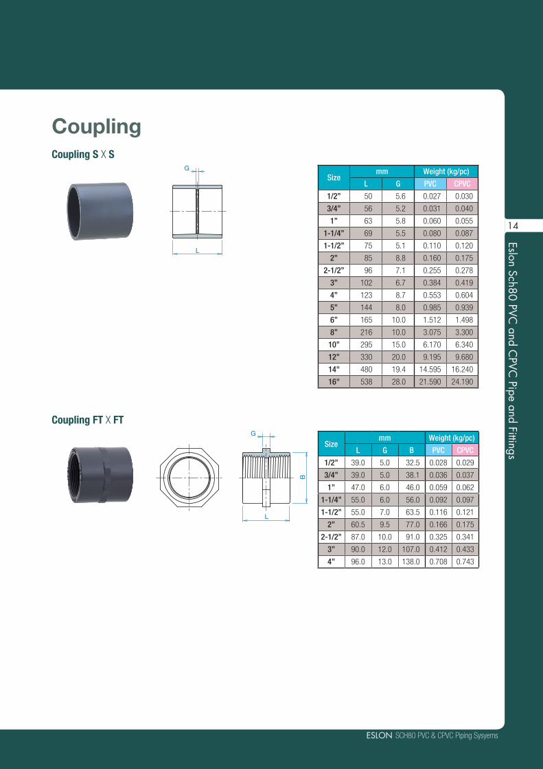
CouplingCoupling S X S
Coupling FT X FT
Sizemm Weight (kg/pc)
L G PVC CPVC
1/2” 50 5.6 0.027 0.030
3/4” 56 5.2 0.031 0.040
1” 63 5.8 0.060 0.055
1-1/4” 69 5.5 0.080 0.087
1-1/2” 75 5.1 0.110 0.120
2” 85 8.8 0.160 0.175
2-1/2” 96 7.1 0.255 0.278
3” 102 6.7 0.384 0.419
4” 123 8.7 0.553 0.604
5” 144 8.0 0.985 0.939
6” 165 10.0 1.512 1.498
8” 216 10.0 3.075 3.300
10” 295 15.0 6.170 6.340
12” 330 20.0 9.195 9.680
14" 480 19.4 14.595 16.240
16" 538 28.0 21.590 24.190
Sizemm Weight (kg/pc)
L G B PVC CPVC
1/2” 39.0 5.0 32.5 0.028 0.029
3/4” 39.0 5.0 38.1 0.036 0.037
1” 47.0 6.0 46.0 0.059 0.062
1-1/4” 55.0 6.0 56.0 0.092 0.097
1-1/2” 55.0 7.0 63.5 0.116 0.121
2” 60.5 9.5 77.0 0.166 0.175
2-1/2” 87.0 10.0 91.0 0.325 0.341
3” 90.0 12.0 107.0 0.412 0.433
4” 96.0 13.0 138.0 0.708 0.743
G
L
L
B
G
14

Eslo
n Sc
h80
PVC
and
CPV
C P
ipe
and
Fitti
ngs
3 Schedule80 Fittings
Reducing CouplingReducing Coupling S X S L
G
Combination Table of Coupling+:Coupling without Bushing +B: with one Bushing +B*2: with 2 pieces of Bushing
Reducing Size1/2" 3/4" 1" 1-1/4" 1-1/2" 2" 2-1/2" 3" 4" 5" 6" 8" 10" 12" 14" 16"
Inle
t Siz
e
1/2" +3/4" + +1" + + +
1-1/4" + + + +1-1/2" + + + + +
2" + + + + + +2-1/2" +B +B +B +B + + +
3" +B +B + +B + + + +4" +B +B +B +B +B + + + +5" +B*2 +B*2 +B +B +B +B +B +B + +
6" +B*2 +B*2 +B +B +B +B +B + + + +
8" +B*2 +B*2 +B +B +B +B +B +B + +B + +
10" +B*2 +B*2 +B*2 +B*2 +B*2 +B*2 +B +B*2 +B + +
12" +B*2 +B*2 +B*2 +B*2 +B*2 +B*2 +B +B*2 +B + + +
14" +B*2 +B*2 +B*2 +B +B +B + +16" +B*2 +B*2 +B*2 +B +B +B + + +
Sizemm Weight (kg/pc)
L G PVC CPVC4" x 2" 125.0 29.8 0.560 0.556
4" x 2-1/2" 125.0 23.4 0.535 0.5844" x 3" 125.0 20.2 0.597 0.6525" x 4" 144.0 18.9 0.860 1.0146" x 3" 168.0 41.9 1.508 1.6466" x 4" 168.0 31.8 1.413 1.5426" x 5" 168.0 21.2 1.494 1.6318" x 4" 218.0 57.9 3.045 3.0038" x 6" 220.0 39.0 2.956 3.22710" x 8" 287.0 44.0 5.622 6.13712" x 8" 331.7 76.7 8.218 8.97112" x 10" 328.0 26.0 8.755 9.58914" x 12" 425.1 40.0 13.060 13.70416" x 12" 493.0 88.0 18.400 20.52016" x 14" 543.2 62.6 25.800 22.580
Sizemm Weight (kg/pc)
L G PVC CPVC3/4" x 1/2" 53.5 5.9 0.034 0.0351" x 1/2" 60.0 9.2 0.049 0.0461" x 3/4" 60.0 6.0 0.045 0.052
1-1/4" x 1/2" 68.0 14.0 0.070 0.0691-1/4" x 3/4" 68.0 10.9 0.068 0.0741-1/4" x 1" 68.0 7.7 0.070 0.076
1-1/2" x 1/2" 75.0 17.9 0.100 0.0901-1/2" x 3/4" 75.0 14.7 0.080 0.1101-1/2" x 1" 75.0 11.5 0.089 0.115
1-1/2" x 1-1/4" 75.0 8.3 0.099 0.1082" x 1/2" 83.0 22.7 0.141 0.1282" x 3/4" 83.0 19.5 0.129 0.1252" x 1" 83.0 16.3 0.124 0.135
2" x 1-1/4" 83.0 13.2 0.134 0.1462" x 1-1/2" 83.0 10.0 0.142 0.180
2-1/2" x 1-1/2" 93.0 13.6 0.205 0.2242-1/2" x 2" 93.0 10.5 0.222 0.242
3" x 1" 106.0 29.8 0.317 0.3463" x 1-1/2" 106.0 23.4 0.313 0.342
3" x 2" 106.0 20.3 0.335 0.3603" x 2-1/2" 106.0 13.9 0.361 0.394
15

SCH80 PVC & CPVC Piping SysyemsESLON
Eslon Sch80 PVC and C
PVC Pipe and Fittings
90°Elbow90°Elbow S X S
90°Elbow S X FT
90°Elbow FT X FT
Sizemm Weight (kg/pc)
G H PVC CPVC
1/2” 15.3 37.5 0.037 0.040
3/4” 17.1 42.5 0.045 0.049
1” 21.4 50.0 0.080 0.100
1-1/4” 26.3 58.0 0.140 0.153
1-1/2” 30.1 65.0 0.185 0.202
2” 35.9 74.0 0.270 0.295
2-1/2” 44.6 89.0 0.464 0.506
3” 53.4 101.0 0.771 0.842
4” 63.9 121.0 1.240 1.354
5” 77.5 150.0 2.185 2.385
6” 93.2 173.0 3.530 3.853
8” 120.1 225.0 7.135 7.788
10” 150.0 290.0 12.585 12.700
12” 172.1 327.1 18.835 19.325
14" 197.0 426.6 26.100 29.230
16" 235.4 492.0 40.890 44.020
Sizemm Weight (kg/pc)
G H PVC CPVC
1/2” 15.0 33.0 0.047 0.054
3/4” 17.0 35.0 0.065 0.074
1” 22.0 43.0 0.100 0.132
1-1/4” 26.3 52.3 0.175 0.217
1-1/2” 30.0 56.0 0.234 0.314
2” 36.0 63.0 0.428 0.471
2-1/2” 44.5 84.5 0.716 0.788
3” 52.0 94.0 1.309 1.440
4” 63.5 108.0 2.165 2.363
Sizemm Weight (kg/pc)
G1 G2 H PVC CPVC
1/2” 15.3 19.5 37.5 0.037 0.040
3/4” 17.1 24.5 42.5 0.045 0.049
1” 21.4 28.0 50.0 0.080 0.087
1-1/4” 26.3 32.0 58.0 0.140 0.153
1-1/2” 30.1 39.0 65.0 0.185 0.202
2” 35.9 47.0 74.0 0.270 0.295
2-1/2” 44.6 49.0 89.0 0.464 0.506
3” 53.4 59.0 101.0 0.771 0.842
4” 63.9 76.6 121.0 1.240 1.354
H
G
H
H
G
H
H
G2
H G1
16

Eslo
n Sc
h80
PVC
and
CPV
C P
ipe
and
Fitti
ngs
3 Schedule80 Fittings
45°Elbow45°Elbow S X S
Sizemm Weight (kg/pc)
G H PVC CPVC
1/2” 7 29 0.030 0.033
3/4” 9 34 0.040 0.044
1” 8 37 0.064 0.070
1-1/4” 11 43 0.102 0.111
1-1/2” 12 47 0.130 0.142
2” 17 55 0.221 0.235
2-1/2” 20 64 0.359 0.392
3” 24 72 0.580 0.633
4” 29 86 0.915 0.999
5” 36 106 1.595 1.741
6” 41 120 2.580 2.816
8” 50 155 4.925 5.376
10” 60 207 9.375 9.960
12” 81 235 15.330 14.865
14" 101 329 21.100 23.180
16" 107 360 28.732 32.540
HG
45°Elbow FT X FT
Sizemm Weight (kg/pc)
G H PVC CPVC
1/2” 6.8 24.8 0.040 0.044
3/4” 8.5 26.5 0.058 0.063
1” 9.5 31.5 0.094 0.103
1-1/4” 11.3 37.3 0.146 0.160
1-1/2” 12.1 38.1 0.200 0.218
2” 17.0 44.0 0.298 0.326
2-1/2” 19.5 64.0 0.537 0.591
3” 24.0 72.0 0.920 1.012
4” 28.5 86.0 1.503 1.640
G
H
45°Elbow S X FT
Sizemm Weight (kg/pc)
G1 G2 H PVC CPVC
1/2” 6.8 8.5 24.0 0.030 0.033
3/4” 8.6 4.4 34.0 0.040 0.044
1” 8.4 10.4 37.0 0.064 0.070
1-1/4” 11.3 15.7 43.0 0.102 0.111
1-1/2” 12.1 16.5 47.0 0.130 0.142
2” 16.4 21.1 55.0 0.140 0.207
2-1/2” 14.6 33.8 64.0 0.354 0.342
3” 24.4 38.5 72.0 0.580 0.633
4” 28.9 50.5 86.0 0.415 0.444
H
G2
G1
17

SCH80 PVC & CPVC Piping SysyemsESLON
Eslon Sch80 PVC and C
PVC Pipe and Fittings
TeeTee S X S X S
H
H
G
Sizemm Weight (kg/pc)
G H PVC CPVC
1/2” 15.3 37.5 0.050 0.055
3/4” 17.1 42.5 0.065 0.071
1” 21.4 50.0 0.105 0.115
1-1/4” 26.3 58.0 0.184 0.201
1-1/2” 30.1 65.0 0.235 0.257
2” 35.9 74.0 0.355 0.388
2-1/2” 44.6 89.0 0.619 0.676
3” 53.4 101.0 1.010 1.102
4” 63.9 121.0 1.581 1.726
5” 79.5 147.5 2.684 2.930
6” 94.6 173.0 4.325 4.721
8” 122.0 225.0 8.980 9.802
10” 150.0 290.0 15.250 16.646
12” 181.8 330.0 25.245 25.830
14” 197.8 426.6 35.885 38.860
16” 236.2 492.0 54.570 58.690
Tee FT X FT X FT
H
H
G
Sizemm Weight (kg/pc)
G H PVC CPVC
1/2” 16.7 33.0 0.066 0.072
3/4” 18.5 35.0 0.091 0.099
1” 22.4 43.0 0.150 0.164
1-1/4” 30.7 52.3 0.249 0.272
1-1/2” 34.4 56.0 0.334 0.365
2” 40.1 63.0 0.503 0.553
2-1/2” 58.8 89.0 0.866 0.946
3” 68.0 101.0 1.467 1.614
4” 86.0 121.0 2.336 2.550
H
H
G
Tee S X S X FT
Sizemm Weight (kg/pc)
G H PVC CPVC
1/2” 15.3 37.5 0.050 0.055
3/4” 17.1 42.5 0.065 0.071
1” 21.4 50.0 0.105 0.115
1-1/4” 26.3 58.0 0.184 0.201
1-1/2” 30.1 65.0 0.235 0.257
2” 35.9 74.0 0.355 0.388
2-1/2” 44.6 89.0 0.619 0.676
3” 53.4 101.0 1.010 1.102
4” 63.9 121.0 1.581 1.726
18
Eslo
n Sc
h80
PVC
and
CPV
C P
ipe
and
Fitti
ngs
3 Schedule80 Fittings
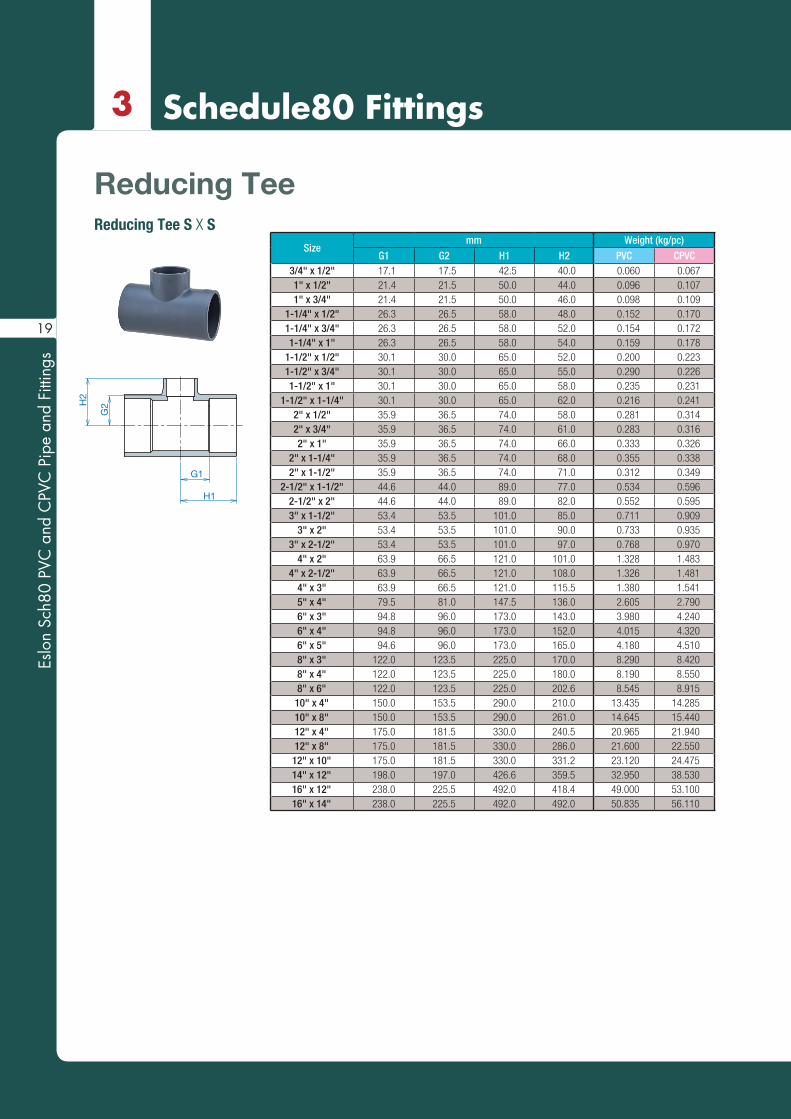
Sizemm Weight (kg/pc)
G1 G2 H1 H2 PVC CPVC3/4" x 1/2" 17.1 17.5 42.5 40.0 0.060 0.0671" x 1/2" 21.4 21.5 50.0 44.0 0.096 0.1071" x 3/4" 21.4 21.5 50.0 46.0 0.098 0.109
1-1/4" x 1/2" 26.3 26.5 58.0 48.0 0.152 0.1701-1/4" x 3/4" 26.3 26.5 58.0 52.0 0.154 0.1721-1/4" x 1" 26.3 26.5 58.0 54.0 0.159 0.178
1-1/2" x 1/2" 30.1 30.0 65.0 52.0 0.200 0.2231-1/2" x 3/4" 30.1 30.0 65.0 55.0 0.290 0.2261-1/2" x 1" 30.1 30.0 65.0 58.0 0.235 0.231
1-1/2" x 1-1/4" 30.1 30.0 65.0 62.0 0.216 0.2412" x 1/2" 35.9 36.5 74.0 58.0 0.281 0.3142" x 3/4" 35.9 36.5 74.0 61.0 0.283 0.3162" x 1" 35.9 36.5 74.0 66.0 0.333 0.326
2" x 1-1/4" 35.9 36.5 74.0 68.0 0.355 0.3382" x 1-1/2" 35.9 36.5 74.0 71.0 0.312 0.349
2-1/2" x 1-1/2" 44.6 44.0 89.0 77.0 0.534 0.5962-1/2" x 2" 44.6 44.0 89.0 82.0 0.552 0.5953" x 1-1/2" 53.4 53.5 101.0 85.0 0.711 0.909
3" x 2" 53.4 53.5 101.0 90.0 0.733 0.9353" x 2-1/2" 53.4 53.5 101.0 97.0 0.768 0.970
4" x 2" 63.9 66.5 121.0 101.0 1.328 1.4834" x 2-1/2" 63.9 66.5 121.0 108.0 1.326 1.481
4" x 3" 63.9 66.5 121.0 115.5 1.380 1.5415" x 4" 79.5 81.0 147.5 136.0 2.605 2.7906" x 3" 94.8 96.0 173.0 143.0 3.980 4.2406" x 4" 94.8 96.0 173.0 152.0 4.015 4.3206" x 5" 94.6 96.0 173.0 165.0 4.180 4.5108" x 3" 122.0 123.5 225.0 170.0 8.290 8.4208" x 4" 122.0 123.5 225.0 180.0 8.190 8.5508" x 6" 122.0 123.5 225.0 202.6 8.545 8.915
10" x 4" 150.0 153.5 290.0 210.0 13.435 14.28510" x 8" 150.0 153.5 290.0 261.0 14.645 15.44012" x 4" 175.0 181.5 330.0 240.5 20.965 21.94012" x 8" 175.0 181.5 330.0 286.0 21.600 22.550
12" x 10" 175.0 181.5 330.0 331.2 23.120 24.47514" x 12" 198.0 197.0 426.6 359.5 32.950 38.53016" x 12" 238.0 225.5 492.0 418.4 49.000 53.10016" x 14" 238.0 225.5 492.0 492.0 50.835 56.110
Reducing TeeReducing Tee S X S
G2
H1
G1
H2
19
SCH80 PVC & CPVC Piping SysyemsESLON
Eslon Sch80 PVC and C
PVC Pipe and Fittings
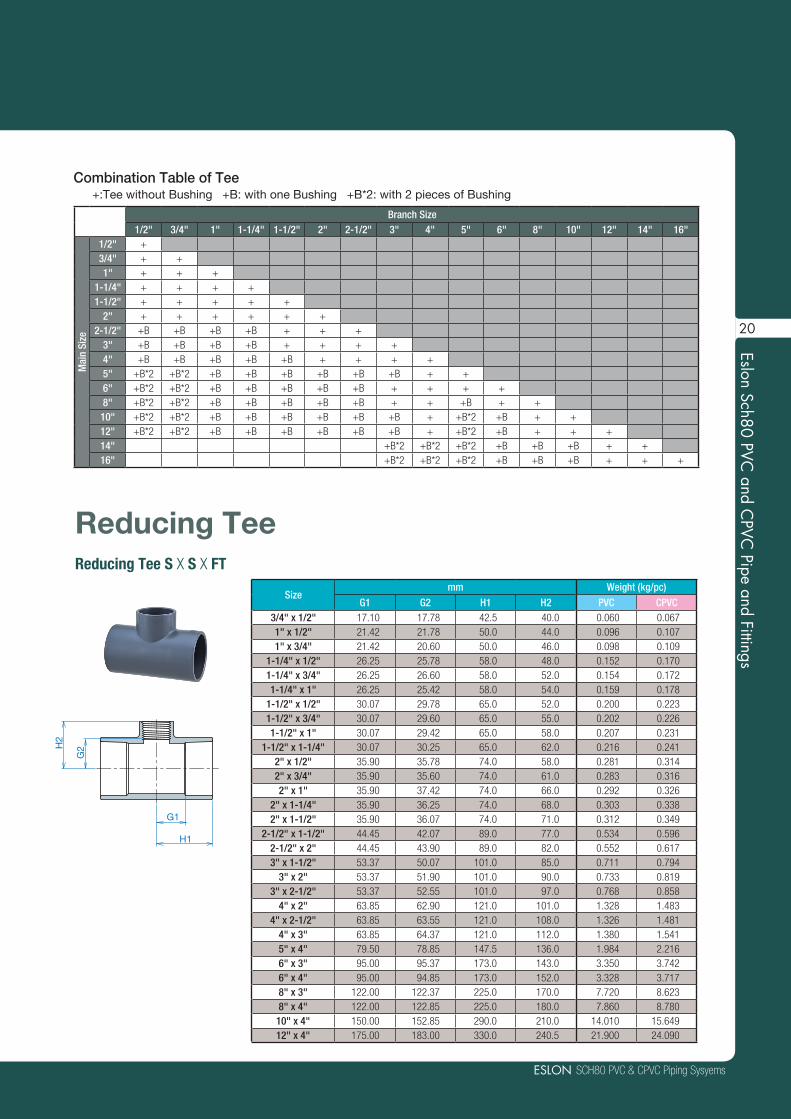
Combination Table of Tee+:Tee without Bushing +B: with one Bushing +B*2: with 2 pieces of Bushing
Branch Size1/2" 3/4" 1" 1-1/4" 1-1/2" 2" 2-1/2" 3" 4" 5" 6" 8" 10" 12" 14" 16"
Mai
n Si
ze
1/2" +3/4" + +1" + + +
1-1/4" + + + +1-1/2" + + + + +
2" + + + + + +2-1/2" +B +B +B +B + + +
3" +B +B +B +B + + + +4" +B +B +B +B +B + + + +5" +B*2 +B*2 +B +B +B +B +B +B + +6" +B*2 +B*2 +B +B +B +B +B + + + +8" +B*2 +B*2 +B +B +B +B +B + + +B + +
10" +B*2 +B*2 +B +B +B +B +B +B + +B*2 +B + +12" +B*2 +B*2 +B +B +B +B +B +B + +B*2 +B + + +14" +B*2 +B*2 +B*2 +B +B +B + +16" +B*2 +B*2 +B*2 +B +B +B + + +
Reducing Tee S X S X FT
Reducing Tee
G2
H1
G1
H2
Sizemm Weight (kg/pc)
G1 G2 H1 H2 PVC CPVC3/4" x 1/2" 17.10 17.78 42.5 40.0 0.060 0.067 1" x 1/2" 21.42 21.78 50.0 44.0 0.096 0.107 1" x 3/4" 21.42 20.60 50.0 46.0 0.098 0.109
1-1/4" x 1/2" 26.25 25.78 58.0 48.0 0.152 0.170 1-1/4" x 3/4" 26.25 26.60 58.0 52.0 0.154 0.172 1-1/4" x 1" 26.25 25.42 58.0 54.0 0.159 0.178
1-1/2" x 1/2" 30.07 29.78 65.0 52.0 0.200 0.223 1-1/2" x 3/4" 30.07 29.60 65.0 55.0 0.202 0.226 1-1/2" x 1" 30.07 29.42 65.0 58.0 0.207 0.231
1-1/2" x 1-1/4" 30.07 30.25 65.0 62.0 0.216 0.241 2" x 1/2" 35.90 35.78 74.0 58.0 0.281 0.314 2" x 3/4" 35.90 35.60 74.0 61.0 0.283 0.316 2" x 1" 35.90 37.42 74.0 66.0 0.292 0.326
2" x 1-1/4" 35.90 36.25 74.0 68.0 0.303 0.338 2" x 1-1/2" 35.90 36.07 74.0 71.0 0.312 0.349
2-1/2" x 1-1/2" 44.45 42.07 89.0 77.0 0.534 0.596 2-1/2" x 2" 44.45 43.90 89.0 82.0 0.552 0.617 3" x 1-1/2" 53.37 50.07 101.0 85.0 0.711 0.794
3" x 2" 53.37 51.90 101.0 90.0 0.733 0.819 3" x 2-1/2" 53.37 52.55 101.0 97.0 0.768 0.858
4" x 2" 63.85 62.90 121.0 101.0 1.328 1.483 4" x 2-1/2" 63.85 63.55 121.0 108.0 1.326 1.481
4" x 3" 63.85 64.37 121.0 112.0 1.380 1.541 5" x 4" 79.50 78.85 147.5 136.0 1.984 2.216 6" x 3" 95.00 95.37 173.0 143.0 3.350 3.742 6" x 4" 95.00 94.85 173.0 152.0 3.328 3.717 8" x 3" 122.00 122.37 225.0 170.0 7.720 8.623 8" x 4" 122.00 122.85 225.0 180.0 7.860 8.780
10" x 4" 150.00 152.85 290.0 210.0 14.010 15.649 12" x 4" 175.00 183.00 330.0 240.5 21.900 24.090
20

Eslo
n Sc
h80
PVC
and
CPV
C P
ipe
and
Fitti
ngs
3 Schedule80 Fittings
Reducing Bushing
Sizemm Weight (kg/pc)
L L1 S PVC CPVC
3/4" x 1/2" 33 25 30 0.014 0.023
1" x 1/2" 36 29 38 0.027 0.030
1" x 3/4" 36 29 38 0.019 0.021
1-1/4" x 1/2" 41 32 47 0.057 0.057
1-1/4" x 3/4" 41 32 47 0.048 0.054
1-1/4" x 1" 41 32 47 0.032 0.040
1-1/2" x 1/2" 44 35 53 0.067 0.075
1-1/2" x 3/4" 44 35 53 0.068 0.076
1-1/2" x 1" 44 35 53 0.058 0.065
1-1/2" x 1-1/4" 44 35 53 0.034 0.038
2" x 1/2" 50 38 66 0.114 0.127
2" x 3/4" 50 38 66 0.114 0.127
2" x 1" 50 38 66 0.116 0.130
2" x 1-1/4" 50 38 66 0.103 0.115
2" x 1-1/2" 50 38 66 0.085 0.095
2-1/2" x 1-1/2" 55 44 78 0.160 0.179
2-1/2" x 2" 55 44 78 0.118 0.132
3" x 1" 58 48 94 0.244 0.273
3" x 1-1/2" 58 48 94 0.258 0.288
3" x 2" 58 48 94 0.245 0.274
3" x 2-1/2" 58 48 94 0.200 0.245
4" x 1" 70 57 120 0.540 0.603
4" x 1-1/4" 70 57 120 0.541 0.575
4" x 1-1/2" 70 57 120 0.515 0.542
4" x 2" 70 57 120 0.528 0.514
4" x 2-1/2" 70 57 120 0.492 0.520
4" x 3" 70 57 120 0.427 0.463
5" x 4" 82 67 150 0.635 0.731
6" x 3" 92 78 175 1.241 1.254
6" x 4" 92 78 175 1.250 1.396
6" x 5" 92 78 175 0.945 0.953
8" x 4" 120 102 230 2.700 2.892
8" x 6" 120 102 230 2.458 2.746
10" x 6" 158 138 285 4.915 5.296
10" x 8" 158 138 285 4.648 5.113
12" x 6" 174 154 340 7.271 7.880
12" x 8" 174 154 340 7.585 7.974
12" x 10" 174 154 340 6.624 6.318
Reducing BushingS X S
L1
L
S
21

SCH80 PVC & CPVC Piping SysyemsESLON
Eslon Sch80 PVC and C
PVC Pipe and Fittings
Sizemm Weight (kg/pc)
L L1 S PVC CPVC
3/4" x 1/2" 33 25 30 0.014 0.021
1" x 1/2" 36 29 38 0.030 0.035
1" x 3/4" 36 29 38 0.030 0.027
1-1/4" x 1/2" 41 32 47 0.060 0.060
1-1/4" x 3/4" 41 32 47 0.054 0.056
1-1/4" x 1" 41 32 47 0.042 0.047
1-1/2" x 1/2" 44 35 53 0.075 0.080
1-1/2" x 3/4" 44 35 53 0.061 0.076
1-1/2" x 1" 44 35 53 0.070 0.076
1-1/2" x 1-1/4" 44 35 53 0.045 0.040
2" x 1/2" 50 38 66 0.114 0.136
2" x 3/4" 50 38 66 0.114 0.134
2" x 1" 50 38 66 0.130 0.140
2" x 1-1/4" 50 38 66 0.120 0.120
2" x 1-1/2" 50 38 66 0.105 0.106
2-1/2" x 1-1/2" 55 44 78 0.190 0.231
2-1/2" x 2" 55 44 78 0.140 0.140
3" x 1" 58 48 94 0.244 0.346
3" x 1-1/2" 58 48 94 0.290 0.342
3" x 2" 58 48 94 0.285 0.287
3" x 2-1/2" 58 48 94 0.225 0.224
4" x 1" 70 57 120 0.540 0.610
4" x 1-1/4" 70 57 120 0.602 0.690
4" x 1-1/2" 70 57 120 0.597 0.733
4" x 2" 70 57 120 0.550 0.550
4" x 2-1/2" 70 57 120 0.520 0.500
4" x 3" 70 57 120 0.395 0.436
5" x 4" 82 67 150 0.474 0.746
6" x 3" 92 78 175 1.271 1.254
6" x 4" 92 78 175 1.250 1.171
8" x 4" 120 102 230 2.430 4.364
Reducing BushingS X FT
L1
L
S
Combination Table for Reducing Bushing+:Bushing +B: with an additional Bushing +B*2: with two additional Bushing
Bushing1/2" 3/4" 1" 1-1/4" 1-1/2" 2" 2-1/2" 3" 4" 5" 6" 8" 10" 12"
Bush
ing
1/2"3/4" +1" + +
1-1/4" + + +1-1/2" + + + +
2" + + + + +2-1/2" +B +B +B +B + +
3" +B +B + +B + + +4" +B +B + + + + + +5" +B*2 +B*2 +B +B +B +B +B +B +6" +B*2 +B*2 +B +B +B +B +B + + +8" +B*2 +B*2 +B +B +B +B +B +B + +B +10" - - +B*2 +B*2 +B*2 +B*2 +B*2 +B*2 +B +B + +12" - - +B*2 +B*2 +B*2 +B*2 +B*2 +B*2 +B +B + + +
22

Eslo
n Sc
h80
PVC
and
CPV
C P
ipe
and
Fitti
ngs
3 Schedule80 Fittings
Female AdapterS X FT
Male AdapterMpt X S
Female Adapter
Male Adapter
Sizemm Weight (kg/pc)
L G B PVC CPVC
1/2” 44 5 33 0.025 0.029
3/4” 47 5 38 0.035 0.035
1” 54 6 46 0.055 0.042
1-1/4” 60 6 56 0.085 0.113
1-1/2” 65 7 64 0.110 0.110
2” 70 10 77 0.165 0.183
2-1/2” 92 10 91 0.292 0.318
3” 96 12 107 0.400 0.357
4” 108 13 138 0.650 0.700
Sizemm Weight (kg/pc)
L d B PVC CPVC
1/2” 46 13 33 0.020 0.020
3/4” 50 18 39 0.025 0.028
1” 56 24 47 0.040 0.045
1-1/4” 63 32 58 0.064 0.071
1-1/2” 66 37 64 0.090 0.101
2” 73 49 77 0.120 0.134
2-1/2” 93 58 94 0.245 0.246
3” 98 72 111 0.300 0.335
4” 112 96 139 0.510 0.570
B
G
LL
L
Bd23

SCH80 PVC & CPVC Piping SysyemsESLON
Eslon Sch80 PVC and C
PVC Pipe and Fittings
Socket Cap
Threaded Cap
Sizemm Weight (kg/pc)
L PVC CPVC
1/2” 30.0 0.016 0.018
3/4” 36.0 0.027 0.025
1” 41.0 0.043 0.040
1-1/4” 47.0 0.058 0.060
1-1/2” 52.0 0.105 0.115
2” 59.0 0.164 0.144
2-1/2” 67.0 0.245 0.224
3” 77.0 0.435 0.460
4” 92.0 0.467 0.687
5” 107.0 0.915 0.980
6” 124.0 1.196 1.480
8” 165.0 2.332 3.190
10” 191.0 5.133 5.310
12” 215.0 7.918 8.155
Sizemm Weight (kg/pc)
L B PVC CPVC
1/2” 28.0 32.5 0.020 0.022
3/4” 31.0 38.1 0.029 0.032
1” 37.0 46.0 0.046 0.050
1-1/4” 41.0 56.0 0.073 0.080
1-1/2” 42.0 63.5 0.110 0.120
2” 46.0 77.0 0.149 0.163
2-1/2” 65.5 91.0 0.257 0.281
3” 73.0 107.0 0.431 0.471
4” 84.5 138.0 0.592 0.646
Cap
L
L
B
24

Eslo
n Sc
h80
PVC
and
CPV
C P
ipe
and
Fitti
ngs
3 Schedule80 Fittings
Nipple
Sizeinch Weight (kg/pc)
L PVC CPVC
1/2” 1-3/4", 2", 3", 4", 5", 6", 8", 10", 12" – –
3/4” 1-3/4", 2", 3", 4", 5", 6", 8", 10", 12" – –
1” 2", 3", 4", 5", 6", 8",10",12" – –
1-1/4” 2", 3", 4", 5", 6", 8", 10", 12" – –
1-1/2” 2", 3", 4", 5", 6", 8", 10", 12" – –
2” 2", 3", 4", 5", 6", 8", 10", 12" – –
2-1/2” 3", 4", 5", 6", 8", 10", 12" – –
3” 4", 5", 6", 8", 10", 12" – –
4” 4", 5", 6", 8", 10", 12" – –
PlugCap and PlugMpt Plug
Sizemm Weight (kg/pc)
L B PVC CPVC
1/2” 24.5 24 0.008 0.009
3/4” 25.0 30 0.012 0.013
1” 28.0 38 0.026 0.028
1-1/4” 32.5 47 0.034 0.037
1-1/2” 33.0 53 0.045 0.049
2” 36.5 65 0.085 0.093
2-1/2” 50.0 79 0.128 0.140
3” 52.0 95 0.193 0.211
4” 54.5 120 0.347 0.379
L
B
CLOSE
L
SHORT
L
LONG
L
25

SCH80 PVC & CPVC Piping SysyemsESLON
Eslon Sch80 PVC and C
PVC Pipe and Fittings
Union (O-Ring Seat)Union (O-Ring Seat) S X S
Union (O-Ring Seat) FT X FT
Sizemm Weight (kg/pc)
L G PVC CPVC
1/2" 52 6.5 0.047 0.050
3/4" 59 7.5 0.073 0.080
1" 67 8.0 0.132 0.140
1-1/4" 76 12.5 0.208 0.217
1-1/2" 82 10.5 0.271 0.295
2" 92 14.0 0.433 0.475
2-1/2" 108 19.0 0.667 0.775
3" 120 25.0 1.093 1.180
4" 152 37.0 1.873 2.050
Sizemm Weight (kg/pc)
L G PVC CPVC
1/2" 52 7.6 0.046 0.050
3/4" 59 8.2 0.073 0.079
1" 67 7.2 0.130 0.143
1-1/4" 76 9.2 0.204 0.223
1-1/2" 82 8.5 0.269 0.294
2" 92 12.0 0.426 0.468
2-1/2" 108 19.1 0.656 0.719
3" 120 24.7 1.076 1.159
4" 152 37.7 1.862 2.031
G
L
G
L
True Union4
O-ring: EPDM. FKM
O-ring: EPDM. FKM
26

Eslo
n Sc
h80
PVC
and
CPV
C P
ipe
and
Fitti
ngs
5 Flange
One Piece FlangeFlange (ANSI) - Socket (ASTM)
D
t
L
C
n-φh
Flange (JIS) - Socket (ASTM)
D
t
L
C
n-φh
Sizemm Weight (kg/pc)
L t C D n h PVC CPVC
1/2" 25.0 14.0 70 95 4 15 0.130 0.150
3/4" 29.5 14.0 75 100 4 15 0.140 0.165
1" 32.0 14.0 90 125 4 19 0.240 0.265
1-1/4" 38.5 16.0 100 135 4 19 0.327 0.304
1-1/2" 40.5 16.0 105 140 4 19 0.320 0.358
2" 45.0 20.0 120 155 4 19 0.473 0.528
2-1/2" 51.0 22.0 140 175 4 19 0.664 1.585
3" 55.0 22.0 150 185 8 19 0.700 0.752
4" 64.0 22.0 175 210 8 19 0.900 0.984
5" 82.0 24.0 210 250 8 23 1.410 1.508
6" 84.5 25.5 240 280 8 23 1.800 1.956
8" 116.0 28.0 290 330 12 23 2.900 3.358
NOTE: Flange bolt hole patterns meet JIS B2220
Sizemm Weight (kg/pc)
L t C D n h PVC CPVC
1/2" 25.0 11.5 60.5 89.0 4 15.7 0.100 0.105
3/4" 29.5 13.0 70.0 98.8 4 15.7 0.140 0.134
1" 32.0 14.5 79.5 108.3 4 15.7 0.191 0.190
1-1/4" 38.5 17.6 89.0 118.8 4 15.7 0.255 0.240
1-1/2" 40.5 19.0 98.5 127.5 4 15.7 0.318 0.360
2" 46.6 19.5 120.5 152.0 4 19.1 0.458 0.512
2-1/2" 51.0 22.5 139.5 177.0 4 19.1 0.749 0.799
3" 55.0 27.1 152.5 192.8 4 19.1 0.880 0.983
4" 64.0 29.3 190.5 229.7 8 19.1 1.340 1.497
5" 82.0 28.0 216.0 254.0 8 22.4 1.648 1.841
6" 84.5 25.5 241.5 279.0 8 22.4 1.912 1.944
8" 116.0 29.0 298.5 343.0 8 22.4 3.400 3.798
NOTE: Flange bolt hole patterns meet ANSI B16.5, class 150
27

SCH80 PVC & CPVC Piping SysyemsESLON
Eslon Sch80 PVC and C
PVC Pipe and Fittings
D
t
L
C
n-φh
Flange (ANSI) -Threaded
Sizemm Weight (kg/pc)
L t C D n h PVC CPVC
1/2" 25.0 11.5 60.5 89.0 4 16 0.094 0.105
3/4" 29.5 13.0 70.0 98.8 4 16 0.120 0.134
1" 32.0 14.5 79.5 108.3 4 16 0.190 0.212
1-1/4" 38.5 18.3 89.0 118.5 4 16 0.240 0.268
1-1/2" 40.5 17.5 98.5 127.5 4 16 0.310 0.346
2" 45.0 19.5 120.5 152.0 4 19 0.458 0.512
2-1/2" 51.0 22.5 139.5 177.0 4 19 0.715 0.799
3" 55.0 24.0 152.5 191.0 4 20 0.880 0.983
4" 64.0 24.0 190.5 229.7 8 19 1.340 1.497
NOTE: Flange bolt hole patterns meet ANSI B16.5, class 150
Van Stone FlangeFlange (ANSI) - Socket (ASTM)
D
t
L
C
n-φh
SizePressure
MPamm Weight (kg/pc)
L t C D n h PVC CPVC
1/2" 1.0 25.0 11.2 60.5 88.9 4 15.9 0.100 0.100
3/4" 1.0 29.5 12.7 70.0 98.6 4 15.9 0.160 0.160
1" 1.0 32.0 14.5 79.5 108.0 4 15.9 0.180 0.180
1 1/4" 1.0 38.5 15.7 89.0 117.4 4 15.9 0.240 0.240
1 1/2" 1.0 40.5 17.5 98.5 127.0 4 15.9 0.290 0.290
2" 1.0 43.0 20.0 120.5 152.0 4 19.1 0.390 0.429
2 1/2" 1.0 51.0 24.5 139.5 178.0 4 19.1 0.595 0.655
3" 1.0 55.0 27.0 152.5 191.0 4 19.1 0.734 0.807
4" 1.0 64.0 28.0 190.5 229.0 8 19.1 1.066 1.173
5" 1.0 82.0 28.0 216.0 254.0 8 22.4 1.423 1.565
6" 1.0 85.0 32.0 241.5 283.2 8 22.4 1.820 2.002
8" 1.0 120.5 36.0 298.5 343.0 8 22.4 2.870 3.157
10" 1.0 150.0 42.0 362.0 406.0 12 25.4 4.923 5.415
12" 1.0 190.0 42.0 432.0 483.0 12 25.4 8.800 9.680
14" 1.0 203.0 51.0 476.0 533.0 12 28.4 11.778 12.329
16" 1.0 225.0 60.0 540.0 597.0 16 28.4 16.620 17.460
18" 1.0 248.0 60.0 578.0 635.0 16 31.8 19.315 21.599
20"0.6
280.0 17.5
635.0 699.0 20 31.8 33.030 46.231
1.0 29.0 47.751 49.554
24"0.6
344.0 19.0
749.0 813.0 20 35.1 60.558 61.931
1.0 32.0 75.704 77.077
NOTE: Flange bolt hole patterns meet ANSI B16.5, class 150
28

Eslo
n Sc
h80
PVC
and
CPV
C P
ipe
and
Fitti
ngs
5 Flange
NOTE: Flange bolt hole patterns meet JIS B2220
Van Stone FlangeFlange (JIS) - Socket (ASTM)
Flange (ANSI)
Sizemm Weight (kg/pc)
L t C D n h PVC CPVC2" 43.0 20.0 120.0 153.0 4 20.0 0.415 0.446
2-1/2" 51.0 24.5 140.0 178.3 4 20.0 0.630 0.683 3" 55.0 27.0 150.0 185.0 8 19.0 0.775 0.770 4" 64.0 28.0 175.0 210.0 8 19.0 0.930 0.990 5" 82.0 28.0 210.0 250.0 8 23.0 1.365 1.657 6" 85.0 32.0 240.0 283.4 8 23.0 1.930 2.124 8" 120.5 36.0 290.0 330.0 12 23.0 3.040 3.927 10" 150.0 42.0 355.0 400.0 12 25.0 4.923 5.686 14" 203.0 14.0 445.0 490.0 16 25.0 12.670 13.365 16" 225.0 14.0 510.0 560.0 16 27.0 17.990 18.850 18" 248.0 14.0 565.0 620.0 20 27.0 23.170 25.277 20" 280.0 15.0 620.0 675.0 20 27.0 34.300 36.103 24" 344.0 15.0 730.0 795.0 24 33.0 59.350 60.723
D
t
L
C
n-φh
Blind Flange
NOTE: Flange bolt hole patterns meet ANSI B16.5 class 150*For more than 14'', please contact us
Sizemm Weight (kg/pc)
t C D n h PVC CPVC
1/2" 12 60.5 89 4 16 0.108 0.100
3/4" 13 70.0 98 4 16 0.148 0.132
1" 15 79.5 108 4 16 0.176 0.190
1-1/4" 16 89.0 117 4 16 0.290 0.238
1-1/2" 18 98.5 127 4 16 0.295 0.329
2" 18 120.5 152 4 19 0.463 0.518
2-1/2" 22 139.5 178 4 19 0.840 0.843
3" 24 152.5 191 4 19 0.928 1.145
4" 24 190.5 229 8 19 1.501 1.262
5" 26 216.0 254 8 22 1.746 1.950
6" 26 241.5 282 8 22 2.229 2.489
8" 28 298.5 343 8 22 3.410 3.809
10" 28 362.0 406 12 25 4.842 4.966
12" 28 432.0 483 12 25 7.010 8.810
14" * 45 476.0 535 12 29 14.905 13.560
16"* 45 540.0 595 16 29 16.843 17.930
18"* 45 578.0 635 16 32 17.942 19.735
20"* 45 635.0 700 20 32 21.642 23.803
24"* 45 749.0 815 20 35 28.130 30.940 n-φh
t
DC
29

SCH80 PVC & CPVC Piping SysyemsESLON
Gasket6
Eslon Sch80 PVC and C
PVC Pipe and Fittings
Sizemm Weight
(kg/pc)N·m{kgf-cm}
d D1 D2 C D n-φh T
1/2" 18 30 - 60.5 85 4-16 5 0.022 16{160}
3/4" 22 32 44 70.0 95 4-16 5 0.029 16{160}
1" 29 38 50 79.5 103 4-16 5 0.034 35{350}
1-1/4" 39 47 59 89.0 111 4-16 5 0.039 35{350}
1-1/2" 44 53 68 98.5 121 4-16 5 0.044 35{350}
2" 55 65 83 120.5 146 4-19 5 0.065 35{350}
2-1/2" 70 81 101 139.5 173 4-19 5 0.084 52{520}
3" 81 94 112 152.5 186 4-19 5 0.098 52{520}
4" 103 124 148 190.5 223 8-19 5 0.137 52{520}
5" 128 150 174 216.0 249 8-22 5 0.153 63{630}
6" 152 172 196 241.5 274 8-22 5 0.182 63{630}
8" 200 222 246 298.5 337 8-22 5 0.258 68{680}
10" 251 276 300 362.0 401 12-25 6 0.348 102{1020}
12" 302 335 365 432.0 477 12-25 6 0.484 136{1360}
Eslon PTFE GasketEslon PTFE Gasket ANSI B16.5
T
20
10
25
3
PTFE
EPDM
Detail at
sealing part
n- h
D
C
d
D1
D2
n-φh
PTFE
Eslon
T
20
10
25
3
PTFE
EPDM
Detail at
sealing part
n- h
D
C
d
D1
D2
n-φh
PTFE
Eslon
Eslon EPDM GasketEslon EPDM Gasket ANSI B16.5
D1
D2
D
d
35
C
EPDM
PTFE
W
H
d
D1
D1
D2
C D3
D2
C
D
5Detail at sealing part
n- h
3
n-φh
Sizemm Weight
(kg/pc)N·m{kgf-cm}
d D1 D2 C D n-φh
1/2" 18 25 38 60.5 86 4-16 0.017 14{140}
3/4" 23 33 48 70.0 97 4-16 0.021 14{140}
1" 30 38 53 79.5 107 4-16 0.025 20{200}
1-1/4" 38 51 66 89.0 114 4-16 0.029 20{200}
1-1/2" 43 53 69 98.5 124 4-16 0.034 20{200}
2" 53 69 84 120.5 150 4-19 0.049 34{340}
2-1/2" 69 86 102 139.5 175 4-19 0.066 34{340}
3" 81 99 112 152.5 188 4-19 0.074 41{410}
4" 102 119 137 190.5 226 8-19 0.101 41{410}
5" 127 145 165 216.0 251 8-22 0.117 55{550}
6" 149 168 191 241.5 277 8-22 0.134 68{680}
8" 198 216 246 298.5 340 8-22 0.192 68{680}
10" 249 269 307 362.0 404 12-25 0.246 89{890}
12" 300 325 353 432.0 480 12-25 0.356 102{1020}
30

Eslon Sch80 PVC & CPVC Piping System

3Installation
1 Storage and Handling ............................................. 33
2 General Recommendations .................................. 35
3 Rules and Guidelines ............................................... 36

Insta
llatio
n
Storage and Handling1
Buyer’s Acceptance of MaterialsThe person responsible for receiving the pipe should always carefully inspect as much of the pipe as
possible before unloading. The receiver should look for transportation damage such as a shift in the load,
tie-down straps overtightened, or signs of rough treatment. LTL (less than truckload) pipe shipments that
arrive in a closed trailer should be checked as soon as the trailer is opened. Make sure that the pipe has
not been toploaded with metallic piping, crates, machinery or any other objects that might crush or im-
pact the plastic pipe. The ends of the pipe should be visually inspected for cracks, cuts, gouges, or heavy
deformations. In some cases, especially for large diameter pipe 4” and above, it would be advisable to
inspect the bore of the pipes for internal cracks or splits that may have occurred as a result of loading
or transportation. The use of a strong flashlight may be necessary to inspect the inside diameter beyond
the ends of the pipe. Any and all damages should be witnessed by the truck driver and clearly noted on
the transportation documentation with a copy retained by the receiver. The carrier and Eslon should be
immediately notified of any damages or missing pipe, or items incorrectly shipped.
Unloading and HandlingAfter the pipe has been thoroughly inspected and inventoried, it should be unloaded with reasonable care
and effort. The person receiving the pipe must decide the means by which the pipe is unloaded and is re-
sponsible for any damages that occur during the unloading process. Never push or drag a palletized load
of pipe from a truck bed. Pipe should not come into severe contact with sharp objects such as corners of
truck beds, loading docks and buildings, forks on forklift trucks, and rocks or other objects on the ground.
Forklift forks must never be inserted into the ends of the pipe as a means of lifting or moving.
NOTE: The impact resistance and flexibility of PVC and especially CPVC pipe are reduced by lower temperature conditions.
The impact strength for both types of piping materials will decrease as temperatures approach 32˚F (0˚C) and below. Ex-
treme care should be taken when unloading and handling pipe in cold weather. Dropping pipe from a truck or forklift can
cause damage. Methods and techniques normally used in warm weather may not be acceptable at the lower temperature
range.
Handling and Storing on Site
Incorrect way to load pipes
Incorrect way to off-load
On-site transport
Correct way to off-load
Correct way to load pipes
DO NOT DRAG
33

SCH80 PVC & CPVC Piping SysyemsESLON
Installation
Pipe StorageIndoor storage of pipe is recommended but may not always be convenient. Therefore, when storing pipe
outdoors, choose a flat, dry location that will minimize dirt and foreign matter accumulation in the bore
and belled end. Palletized pipe should be stacked with wooden pallet bracings touching each other.
Stack height will depend on the pipe diameter, the slope of the terrain, and the weather conditions. As
a general precaution, palletized pipe should not be stacked higher that eight feet. This should be deter-
mined and approved by the site engineer or responsible management official. Loose pipe lengths should
be stored in racks or dunnage that will evenly support the pipe to prevent longitudinal sag. If pipe is not
well supported, especially in warmer weather, it will become permanently bowed and will be difficult to
install. The pipe must be protected from the sun and extreme heat. Protect the pipe by covering it with an
opaque tarp, leaving the ends open to allow for air circulation through and around the pipe. When pipe
is not protected from the sun, extended exposure to ultraviolet rays will cause discoloration. The amount
of time in years necessary to cause this will vary with the geographic location and the orientation of the
pipe to the sun.
Fitting StorageThe person responsible for receiving the fittings should take an accurate count of the incoming order and
report any discrepancies to Eslon and the carrier. Fittings packaged in damaged boxes should be closely
inspected. Store fittings in their original packaging. If they must be removed from their boxes, separate
them by material type (PVC vs. CPVC), geometric configuration, and diameter size. Never combine your
plastic fitting inventory with metallic materials. Avoid storing fittings near an open flame or source of ex-
treme heat.
Max
8 fe
et (2
.5m
)
Max
8 fe
et (2
.5m
)
75mm minimum widthMin 3 feet (1m)
Shade
Min 3 feet (1m) SpacingOutdoor Storage Indoor Storage
Ground Level
34

General Recommendations
Insta
llatio
n
2
WARNINGFailure to follow the safety precautions below may
result in misapplication or improper installation and
testing which can cause severe personal injury and/
or property damage.
1. Solvent Cement WeldingThis method of joining is very simple and reliable if
it is followed correctly, but any deviations from the
recommended basic steps may reduce the strength
and integrity of the joint. The procedures for prepa-
ration, insertion, and curing should be followed very
carefully.
2. Expansion and ContractionThe coefficient of linear expansion of PVC and CPVC
pipe is greater than that of metallic piping; therefore,
take this factor into consideration when designing
and installing a PVC or CPVC piping system.
3. Hanging and SupportingThe modulus of elasticity of PVC and CPVC pipe is
smaller than that of metal pipes. Maximum work-
ing temperature and room temperature should be
considered when determining the required support
spacing.
4. Trench PreparationWhen laying PVC and CPVC pipe below the ground,
care should be taken to remove all rocks, boards,
empty primer and cement cans, brushes, bottles
and other debris from the trench. Smaller diameters
of pipe should be “snaked” in the trench to allow for
expansion and contraction. If solvent cement welding
is used for the method of joining, snaking, pressure
testing, and pipe movement should not be done until
after the joints have been given sufficient time to dry.
5. Avoid Bending PipePipe should not be bent in trenches or in above
ground installations. Pipe and joints that are stressed
can reduce pressure rating and cause failures.
6. Protect Plastic Pipe from Contact with Hard and Pointed Objects.Impact resistance is lower than for metals.
WARNINGNEVER use compressed air or gas in PVC/CPVC pipe
and fittings.
NEVER test PVC/CPVC pipe and fittings with com-
pressed air or gas, or air-over-water boosters.w
ONLY use PVC/CPVC pipe for water and approved
chemicals.
Use of compressed air or gas in PVC/CPVC pipe
and fittings can result in explosive failures and cause
severe injury or death.
7. Testing7.1 NEVER use compressed air, gas or air-over-wa-
ter boosters to pressure test PVC or CPVC piping
systems. ONLY hydrostatic pressure testing is to
be conducted on PVC and CPVC piping systems.
Compressed air or gases can surge to high pres-
sures and cause explosive failures that could seri-
ously injure personnel.
7.2 Carefully follow all instructions for hydrostatic
pressure testing. Failure to follow these instructions
can result in a system failure.
7.3 Before water-testing a system, always bleed all
entrapped air from system. Entrapped air is a ma-
jor cause of surge and burst failure in plastic piping
systems.
! !
35

SCH80 PVC & CPVC Piping SysyemsESLON
Installation
Joining Equipment and Material- Cutting Tool
Saw & Miter Box or Pipe Cutter (Ratchet Type,
Wheel Type)
- Pipe deburring & beveling tool, file or knife- Solvent Cement
PVC cement for PVC materials, CPVC cement
for CPVC materials
- Primer- Cleaner- Cotton Rag- Square- Scale- Felt-tip Pen- Tape Measure- Brush- Insertion Tool (6” and above)- Container (Metal Cans to Hold Cement or Primer)
1. Cutting ①②③④Pipe ends must be cut square.
Check the pipe end with a square to make sure it
has been cut squarely.
Note: A diagonal cut reduces bonding area in the most
effective and critical part of the joint.
Wheel type cutters are not generally recommended for large
diameters since they tend to raise flare at the pipe end.
This flare must be removed with a file or deburring tool,
as it will scrape the cement away when pipe is inserted
into the fitting.
Solvent Cement Welding Joints
Rules and Guidelines3
①
②
③
④
36

Insta
llatio
n
3 Rules and Guidelines
2. Deburring ⑤All burrs, chips, filings, etc., should be removed
from both around the pipe before joining.
Use a knife, deburring tool or a half-round coarse
file.
All pipe ends should be beveled from 45 degrees.
Note: Failure to chamfer the edge of the pipe may remove
cement from the fitting socket, causing the joint to leak.
3. Inspection, Cleaning ⑥⑦Visually inspect the inside of the pipe and fitting
sockets and remove all dirt, grease or moisture
with a clean dry rag.
Check pipes and fittings possible damage such
as splits or cracks and replace if necessary.
4. Test Dry Fit of the JointCheck pipe and fittings for dry fit before cementing.
The pipe should be inserted to the fitting easily
about 1/3 to 2/3 of the socket depth.
5. Depth-Of-Entry Mark ⑧⑨Measure the socket depth of the fitting and mark
this distance on the pipe O.D.
This reference mark can be used when joining to
ensure the pipe is completely bottomed into the
fitting during assembly.
6. Priming ⑩⑪This process is necessary to penetrate and soften
both pipe and fitting socket surfaces for cement-
ing process.
Apply primer to the surface of the pipe and fitting
socket with a natural bristle brush.
Move quickly without hesitation to the cement-
ing procedure while surfaces are still wet with
primer.
⑤
⑧
⑨
⑦
⑥
37

SCH80 PVC & CPVC Piping SysyemsESLON
Installation
7. Application of Solvent Cement ⑫⑬Apply the solvent cement evenly and quickly
around the outside of the pipe at a width a little
greater than the depth of the fitting socket while
the primer is still wet.
Apply a light coat of cement evenly around the
inside of the fitting socket. Avoid puddling.
Apply a second coat of cement to the pipe end.
NOTE: Read all warnings on primer and cement cans.
8. Joint Assembly ⑭Work quickly, insert the pipe into the fitting socket
bottom with a one-quarter turn to evenly distribute
the cement.
Do not continue to rotate the pipe after it has
reached the bottom of the fitting socket.
A good joint will have sufficient cement to make a
bead all the way around the outside of the fitting
hub.
Hold the pipe and fitting together for a minimum
of 30 seconds to make sure the pipe does not
move or push out of the socket.
9. Cleanup ⑮Remove all excess cement from around the pipe
and fitting with a dry cotton rag while the cement
is still soft.
⑩
⑪
Recommended Brush Size for Primer and Cement ApplicationNominal
PipeSize
1/2 3/4 1 1-1/4 1-1/2 2 2-1/2 3 4 5 6 8 10 12
BrushWidth 1/2 1 1 1 1-1/2 1-1/2
1-1/2 to2
1-1/2to
2-1/2
2to3
33to5
4to6
6to8
6to8
* Use Only Natural Bristle
⑫
⑬
⑭
⑮
38
Insta
llatio
n
3 Rules and Guidelines
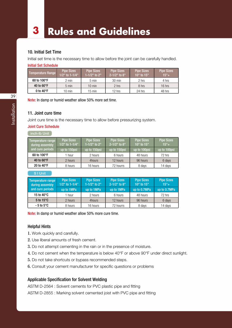
10. Initial Set TimeInitial set time is the necessary time to allow before the joint can be carefully handled.
Initial Set Schedule
Temperature RangePipe Sizes
1/2" to 1-1/4"Pipe Sizes
1-1/2" to 2"Pipe Sizes
2-1/2" to 8"Pipe Sizes10" to 15"
Pipe Sizes15"+
60 to 100°F 2 min 5 min 30 min 2 hrs 4 hrs
40 to 60°F 5 min 10 min 2 hrs 8 hrs 16 hrs
0 to 40°F 10 min 15 min 12 hrs 24 hrs 48 hrs
Note: In damp or humid weather allow 50% more set time.
11. Joint cure timeJoint cure time is the necessary time to allow before pressurizing system.
Joint Cure Schedule
inch-lb Unit
Temperature rangeduring assemblyand cure periods
Pipe Sizes1/2" to 1-1/4"
Pipe Sizes1-1/2" to 2"
Pipe Sizes2-1/2" to 8"
Pipe Sizes10" to 15"
Pipe Sizes15"+
up to 150psi up to 150psi up to 150psi up to 100psi up to 100psi
60 to 100°F 1 hour 2 hours 6 hours 48 hours 72 hrs
40 to 60°F 2 hours 4hours 12 hours 96 hours 6 days
20 to 40°F 8 hours 16 hours 72 hourrs 8 days 14 days
S I Unit
Temperature rangeduring assemblyand cure periods
Pipe Sizes1/2" to 1-1/4"
Pipe Sizes1-1/2" to 2"
Pipe Sizes2-1/2" to 8"
Pipe Sizes10" to 15"
Pipe Sizes15"+
up to 1MPa up to 1MPa up to 1MPa up to 0.7MPa up to 0.7MPa
15 to 40°C 1 hour 2 hours 6 hours 48 hours 72 hrs
5 to 15°C 2 hours 4hours 12 hours 96 hours 6 days
- 5 to 5°C 8 hours 16 hours 72 hourrs 8 days 14 days
Note: In damp or humid weather allow 50% more cure time.
Helpful Hints1. Work quickly and carefully.
2. Use liberal amounts of fresh cement.
3. Do not attempt cementing in the rain or in the presence of moisture.
4. Do not cement when the temperature is below 40°F or above 90°F under direct sunlight.
5. Do not take shortcuts or bypass recommended steps.
6. Consult your cement manufacturer for specific questions or problems
Applicable Specification for Solvent WeldingASTM D-2564 : Solvent cements for PVC plastic pipe and fitting
ASTM D-2855 : Marking solvent cemented joist with PVC pipe and fitting
39
SCH80 PVC & CPVC Piping SysyemsESLON
Installation
ASTM A-493 : Solvent cements for CPVC plastic
pipe and fitting
ASTM A-656 : Primers for use in solvent cement
joints of PVC plastic pipe and fitting
Hydrostatic Pressure Testing
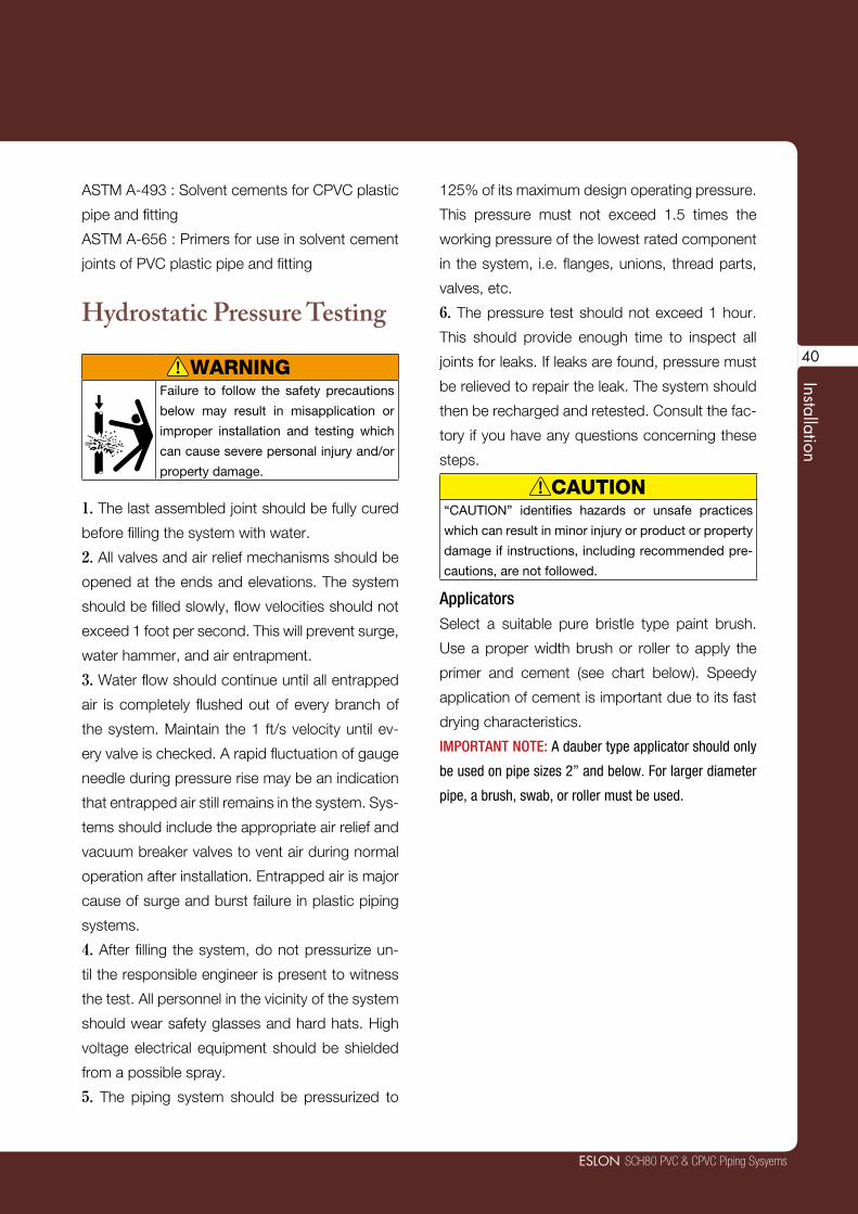
WARNINGFailure to follow the safety precautions
below may result in misapplication or
improper installation and testing which
can cause severe personal injury and/or
property damage.
1. The last assembled joint should be fully cured
before filling the system with water.
2. All valves and air relief mechanisms should be
opened at the ends and elevations. The system
should be filled slowly, flow velocities should not
exceed 1 foot per second. This will prevent surge,
water hammer, and air entrapment.
3. Water flow should continue until all entrapped
air is completely flushed out of every branch of
the system. Maintain the 1 ft/s velocity until ev-
ery valve is checked. A rapid fluctuation of gauge
needle during pressure rise may be an indication
that entrapped air still remains in the system. Sys-
tems should include the appropriate air relief and
vacuum breaker valves to vent air during normal
operation after installation. Entrapped air is major
cause of surge and burst failure in plastic piping
systems.
4. After filling the system, do not pressurize un-
til the responsible engineer is present to witness
the test. All personnel in the vicinity of the system
should wear safety glasses and hard hats. High
voltage electrical equipment should be shielded
from a possible spray.
5. The piping system should be pressurized to
125% of its maximum design operating pressure.
This pressure must not exceed 1.5 times the
working pressure of the lowest rated component
in the system, i.e. flanges, unions, thread parts,
valves, etc.
6. The pressure test should not exceed 1 hour.
This should provide enough time to inspect all
joints for leaks. If leaks are found, pressure must
be relieved to repair the leak. The system should
then be recharged and retested. Consult the fac-
tory if you have any questions concerning these
steps.
CAUTION“CAUTION” identifies hazards or unsafe practices
which can result in minor injury or product or property
damage if instructions, including recommended pre-
cautions, are not followed.
ApplicatorsSelect a suitable pure bristle type paint brush.
Use a proper width brush or roller to apply the
primer and cement (see chart below). Speedy
application of cement is important due to its fast
drying characteristics.
IMPORTANT NOTE: A dauber type applicator should only
be used on pipe sizes 2” and below. For larger diameter
pipe, a brush, swab, or roller must be used.
!
!
40

Insta
llatio
n
3 Rules and Guidelines
A. Selection of MaterialsPower Threading Machine
Threading Rachet and Pipe Vise (if hand pipe
stock is used)
Pipe Dies designed for plastic
Strap Wrench
Teflon* Tape or an approved Teflon Paste
Cutting and Deburring Tool
Ring Gauge (L-1)
*Trademark of the EJ DuPont Company
B. Making the Pipe Thread1. Cutting and DeburringPVC or CPVC pipe should be cut square and
smooth for easy and accurate threading. A miter
box or similar guide should be used when sawing
is done by hand. Burrs should be removed inside
and out using a knife or plastic pipe deburring
tool.
2. ThreadingThreading Schedule 80 PVC and CPVC pipe can
easily be accomplished using either a standard
hand pipe stock or a power operated tool. Cutting
dies should be clean and sharp. Power thread-
ing machines should be fitted with dies having
a 5˚negative front rake and ground especially for
plastic pipe. Self-opening die heads, and a slight
chamfer to lead the dies will speed the operation;
however, dies should not be driven at high speeds
or with heavy pressure. When using a hand held
cutter, the pipe should be held in a pipe vise. To
prevent crushing or scoring of the pipe by the
vice jaws, some type of protective wrap such as
canvas, emery paper, rubber, or light metal sleeve
should be used. For hand stocks, the dies should
have a negative front rake angle of 5˚ to 10˚ PVC
and CPVC is readily threaded and caution should
be taken not to over-thread.
3. Preparing the Threaded PipeA ring gauge should be used to check the ac-
curacy of the threads. Tolerance = ± 1-1/2 turns.
The threads should then be cleaned by brushing
away cuttings and ribbons.
After cleaning, apply a thread lubricant such as
Teflon tape to the threaded portion of pipe. Wrap
the tape around the entire length of threads be-
ginning with number two thread from the end.
The tape should slightly overlap itself going in
the same direction as the threads. This will pre-
vent the tape from unraveling when the fitting is
tightened on the pipe. Overlapping in the wrong
direction and the use of too much tape can affect
tolerances between threads. This can generate
stress in the wall of female fittings resulting in fail-
ure during operations.
2 Threaded Connection
41
SCH80 PVC & CPVC Piping SysyemsESLON
Installation
4. Assembly of Threaded JointsAfter applying thread lubricant, screw the thread-
ed fitting onto the pipe. Screwed fittings should
be started carefully and hand tightened. Threads
must be properly cut and a good quality thread
lubricant/tape must be used. If desired, the joint
may be tightened with a strap wrench. IN NO
CASE SHOULD A STILLSON TYPE WRENCH
BE USED. The jaws of this type of wrench will
scar and damage the pipe wall. Fittings should
be threaded together until hand tight with an ad-
ditional 1 to 1-1/2 turns more. Avoid stretching
or distorting the pipe, fittings or threads by over
tightening.
NOTE:
(1.) Never apply solvent cement to threaded pipe or
threaded fittings. Do not allow cleaners, primers, or sol-
vent cements to “run” or drip into the threaded portion
of the fitting.
(2.) Some Teflon pastes contain chemicals that may be
harmful to the pipe and fittings. You should consult the
supplier or manufacturer of the paste before use.
(3.) Avoid screwing metallic’ male threads into plastic
female threads. If connections to metal threads have to
be made, the preferred method is to screw a plastic male
thread into a metallic female thread. There are a variety
of plastic fittings that are molded with metallic male or
female NPT threaded inserts. The corrosion resistance of
the metal insert will have to be taken into consideration.
Consult the factory or your Eslon sales person for the
availability of these metal insert fittings.
*Trademark of the E.I. DuPont Company.
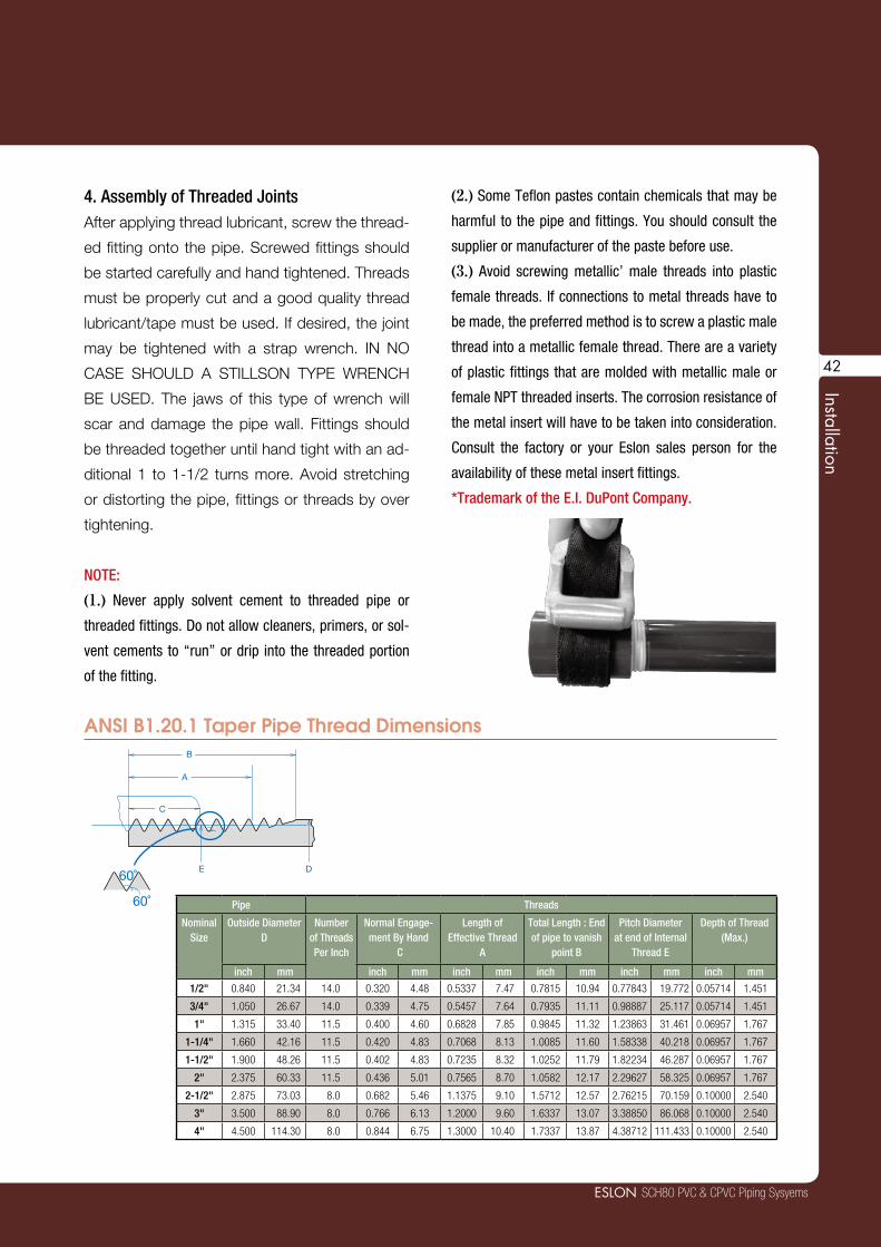
ANSI B1.20.1 Taper Pipe Thread Dimensions
DE
C
B
A
60˚
60˚ Pipe Threads
NominalSize
Outside Diameter D
Number of Threads Per Inch
Normal Engage-ment By Hand
C
Length of Effective Thread
A
Total Length : End of pipe to vanish
point B
Pitch Diameter at end of Internal
Thread E
Depth of Thread (Max.)
inch mm inch mm inch mm inch mm inch mm inch mm
1/2" 0.840 21.34 14.0 0.320 4.48 0.5337 7.47 0.7815 10.94 0.77843 19.772 0.05714 1.451
3/4" 1.050 26.67 14.0 0.339 4.75 0.5457 7.64 0.7935 11.11 0.98887 25.117 0.05714 1.451
1" 1.315 33.40 11.5 0.400 4.60 0.6828 7.85 0.9845 11.32 1.23863 31.461 0.06957 1.767
1-1/4" 1.660 42.16 11.5 0.420 4.83 0.7068 8.13 1.0085 11.60 1.58338 40.218 0.06957 1.767
1-1/2" 1.900 48.26 11.5 0.402 4.83 0.7235 8.32 1.0252 11.79 1.82234 46.287 0.06957 1.767
2" 2.375 60.33 11.5 0.436 5.01 0.7565 8.70 1.0582 12.17 2.29627 58.325 0.06957 1.767
2-1/2" 2.875 73.03 8.0 0.682 5.46 1.1375 9.10 1.5712 12.57 2.76215 70.159 0.10000 2.540
3" 3.500 88.90 8.0 0.766 6.13 1.2000 9.60 1.6337 13.07 3.38850 86.068 0.10000 2.540
4" 4.500 114.30 8.0 0.844 6.75 1.3000 10.40 1.7337 13.87 4.38712 111.433 0.10000 2.540
42
Insta
llatio
n
3 Rules and Guidelines
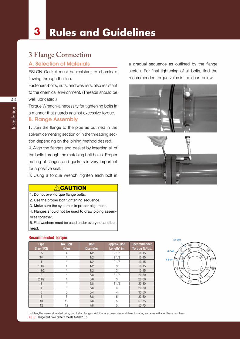
A. Selection of MaterialsESLON Gasket must be resistant to chemicals
flowing through the line.
Fasteners-bolts, nuts, and washers, also resistant
to the chemical environment. (Threads should be
well lubricated.)
Torque Wrench-a necessity for tightening bolts in
a manner that guards against excessive torque.
B. Flange Assembly1. Join the flange to the pipe as outlined in the
solvent cementing section or in the threading sec-
tion depending on the joining method desired.
2. Align the flanges and gasket by inserting all of
the bolts through the matching bolt holes. Proper
mating of flanges and gaskets is very important
for a positive seal.
3. Using a torque wrench, tighten each bolt in
a gradual sequence as outlined by the flange
sketch. For final tightening of all bolts, find the
recommended torque value in the chart below.
3 Flange Connection
CAUTION1. Do not over-torque flange bolts.
2. Use the proper bolt tightening sequence.
3. Make sure the system is in proper alignment.
4. Flanges should not be used to draw piping assem-
blies together.
5. Flat washers must be used under every nut and bolt
head.
Recommended TorquePipe
Size (IPS)No. BoltHoles
BoltDiameter
Approx. BoltLength* in.
RecommendedTorque ft./lbs.
1/2 4 1/2 2 1/2 10-153/4 4 1/2 2 1/2 10-151 4 1/2 2 1/2 10-15
1 1/4 4 1/2 3 10-151 1/2 4 1/2 3 10-15
2 4 5/8 3 1/2 20-302 1/2 4 5/8 3 20-30
3 4 5/8 3 1/2 20-304 8 5/8 4 20-306 8 3/4 4 33-508 8 7/8 5 33-50
10 12 7/8 5 53-7512 12 7/8 5 53-75
Bolt lengths were calculated using two Eaton flanges. Additional accessories or different mating surfaces will alter these numbersNOTE: Flange bolt hole pattern meets ANSI B16.5
⑦ ⑦
⑤
⑤
①①
①
⑧ ⑧
⑥
⑨
⑪⑥
④
12-Bolt
8-Bolt
4-Bolt ④ ④
⑩
②②
②
⑫
③ ③③
!
43

4Safety Precautions
Safety Precautions
Safe
ty P
reca
utio
ns
45
PVC and CPVC plastic piping systems will give
excellent, maintenance-free performance over
many years use,as long as the application and
system design is correct and installation is prop-
erly done. It is most important to know the physi-
cal properties and limitations of PVC and CPVC
plastic pipe when selecting these materials for
an application and when designing the system.
In every case, carefully read and follow installa-
tion procedures. It is very important to know the
reputation and abilities of your installation crew or
contractor. Professional engineering design of the
system and close supervision of the assembly-
installation procedures are highly recommended.
Any questions concerning the application or in-
stallation of PVC and CPVC piping products
should be directed to the supplier, manufacturer
or consultant.
WARNINGFailure to follow the safety precautions below may
result in misapplication or improper installation and
testing which can cause severe personal injury and/
or property damage.
General 1. Protect plastic pipe from contact with hard and pointed objectsImpact resistance is lower than for metals.
2. Avoid bending pipePipe should not be bent in trenches or in above
ground installations. Pipe and joints that are
stressed reduce pressure rating and can cause
failures.
3. Protect pipe from extreme heat and cold.Extremes of heat and cold can cause failure. Al-
lowing liquids to freeze inside PVC/CPVC and
metallic piping can cause the pipe and/or the
joints to crack. Freeze protection should be de-
signed into the system. Heat beyond design lim-
its can also cause failures.
4. Protect pipe from sunlight.PVC and CPVC pipe compounds normally do not
provide extended protection from the ultraviolet
rays of the sun. Therefore, unless the material
has been specially formulated to provide protec-
tion, the product must be protected from sunlight
or some damage may occur after years of expo-
sure.
Application 1. NEVER use PVC and CPVC piping materials to transport compressed air or gases. Compressed air or gases can surge to high pres-
sures and cause explosive failures that could se-
riously injure personnel. PVC and CPVC pipe and
fittings are excellent products in transporting wa-
ter and corrosive chemicals.
2. Only use approved chemicals.Certain chemicals, especially petroleum distillates
and derivatives, can cause failure. Every chemical
should be verified and approved in the manufac-
turer's chemical resistance chart.
System Design 1. Allow for flexibility in the design of the system.Expansion and contraction is greater than for
metals. This can cause breaks and leaking points
if system design is not flexible to allow for move-
ment. When laying smaller diameters of pipe be-
low ground, the pipe should be "snaked" in the
trench to allow for expansion and contraction. If
solvent cement welding is used for the method
of joining, snaking, pressure testing, and pipe
movement should not be done until after the
joints have been given sufficient time to dry.
!
SCH80 PVC & CPVC Piping SysyemsESLON
Safety Precautions
46
2. Design safeguards into the system to prevent excessive surge pressures.Water hammer (surge) in a PVC and CPVC sys-
tem can cause pipe, fittings, and valves to burst.
Liquid velocities should not exceed five feet per
second maximum.
Installation1. Carefully follow solvent cement welding in-structions.Failure to correctly follow application procedures
can reduce the strength and integrity of joints and
cause joint failures. By far, the majority of failures
in PVC and CPVC systems are the result of short-
cuts and/or improper joining techniques.
2. Remove rocks and other debris that can rup-ture pipe when burying pipe in trenches.When laying PVC and CPVC pipe below the
ground, care should be taken to remove all rocks,
boards, empty primer and cement cans, brushes,
bottles and other debris from the trench. Backfill-
ing and top loading should be watched very care-
fully.
3. Follow recommended support spacing for PVC and CPVC piping systems.The modulus of elasticity of PVC and CPVC pipe
is smaller than metals. Maximum working tem-
perature and room temperature should be con-
sidered when determining the required support
spacing.
Testing1. NEVER use compressed air or gas or air-over-water boosters to pressure test PVC or CPVC piping systems.ONLY hydrostatic pressure testing is to be con-
ducted on PVC and CPVC piping systems. Com-
pressed air or gases can surge to high pressures
and cause explosive failures that could seriously
injure personnel.
2. Carefully follow all instructions for hydrostatic pressure testing.Failure to follow these instructions can result in a
system failure.
3. Before water-testing a system, always bleed all entrapped air from system.Entrapped air is a major cause of surge and burst
failure in plastic piping systems.

SCH80 PVC & CPVC Piping SystemsSpecifications & Engineering Manual
ESLON
11. 2016 3rd Edition
Copyright 2008SEKISUI CHEMICAL CO., LTD.May not be copied in whole or part.
Revision No.1, Jan. 2008
2016. 11. 3TH TXNo. 06270
Printed November.2016.3rd EditionESLON SCH80 PVC & CPVC Piping SystemsSpecifications & Engineering ManualSEKISUI CHEMICAL CO.,LTD.Industrial Piping System Division
http://www.eslon-plant.jp E-mail: [email protected]
Industrial Piping System Division
SEKISUI CHEMICAL CO.,LTD.2-3-17 Toranomon Minatoku,Tokyo,105-8450 JapanTEL +81-3-5521-0555 FAX +81-3-5521-0753
SEKISUI INDUSTRIAL PIPING CO., LTD.No.18, Jing 1st Rd.,Chung Kang Export Processing Zone, Wuqi Dist., Taichung City 43541, Taiwan, R.O.C.TEL +886-4-2657-3688 FAX +886-4-2657-9638
SEKISUI (SHANGHAI) INTERNATIONAL TRADING CO., LTD.Room 702-707, Metro Tower, No.30, Tianyaoqiao Road Shanghai. 200030, ChinaTEL +86-21-6482-0638 FAX +86-21-6482-0639
SEKISUI CHEMICAL SINGAPORE (PTE.) LTD.2 Jurong East Street Road 21,#05-17,IMM Building,Singapore 609601TEL +65-6562-5081 FAX +65-6562-5021
SEKISUI CHEMICAL G.m.b.H.Cantadorstr.3 40211 Dusseldorf, GermanyTEL +49-211-36977-0 FAX +49-211-36977-31
SEKISUI VIETNAM CO.,LTDRoom1414, CornerStone Building, 16Phan Chu Trinh St, Hoan Kiem District, Hanoi, VietnamTEL +84-4-3939-2677 FAX +84-4-3939-2678


