1
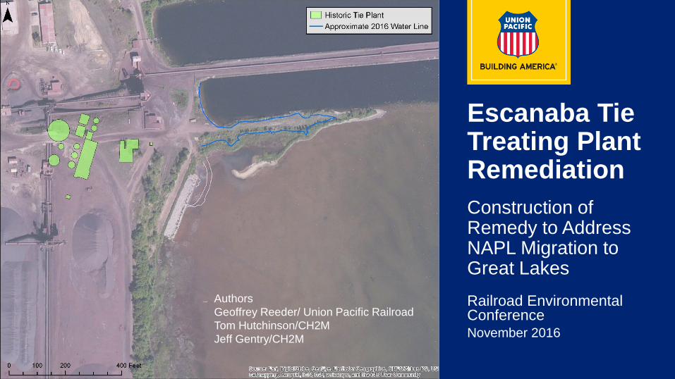
Escanaba Tie Treating Plant Remediation
Railroad Environmental ConferenceNovember 2016
Construction of Remedy to Address NAPL Migration to Great Lakes
AuthorsGeoffrey Reeder/ Union Pacific RailroadTom Hutchinson/CH2MJeff Gentry/CH2M
2
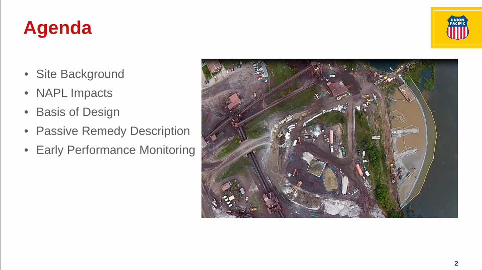
• Site Background• NAPL Impacts• Basis of Design• Passive Remedy Description• Early Performance Monitoring
Agenda
3
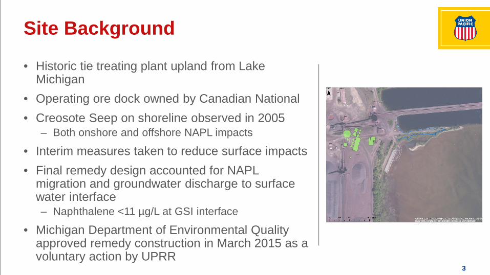
• Historic tie treating plant upland from Lake Michigan
• Operating ore dock owned by Canadian National• Creosote Seep on shoreline observed in 2005
– Both onshore and offshore NAPL impacts
• Interim measures taken to reduce surface impacts• Final remedy design accounted for NAPL
migration and groundwater discharge to surface water interface– Naphthalene <11 µg/L at GSI interface
• Michigan Department of Environmental Quality approved remedy construction in March 2015 as a voluntary action by UPRR
Site Background

4
Site Overview
5
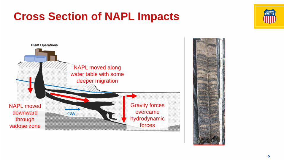
Cross Section of NAPL Impacts
NAPL moved downward
through vadose zone
NAPL moved along water table with some
deeper migration
GW
Gravity forces overcame
hydrodynamic forces
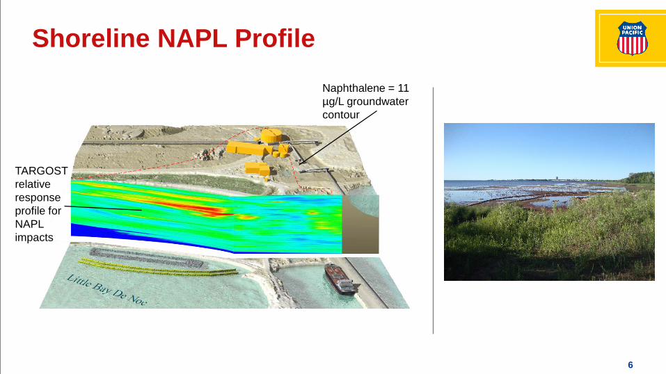
6
Shoreline NAPL ProfileNaphthalene = 11 µg/L groundwater contour
TARGOST relative response profile for NAPL impacts
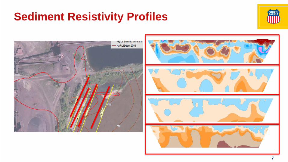
7
Sediment Resistivity Profiles
8
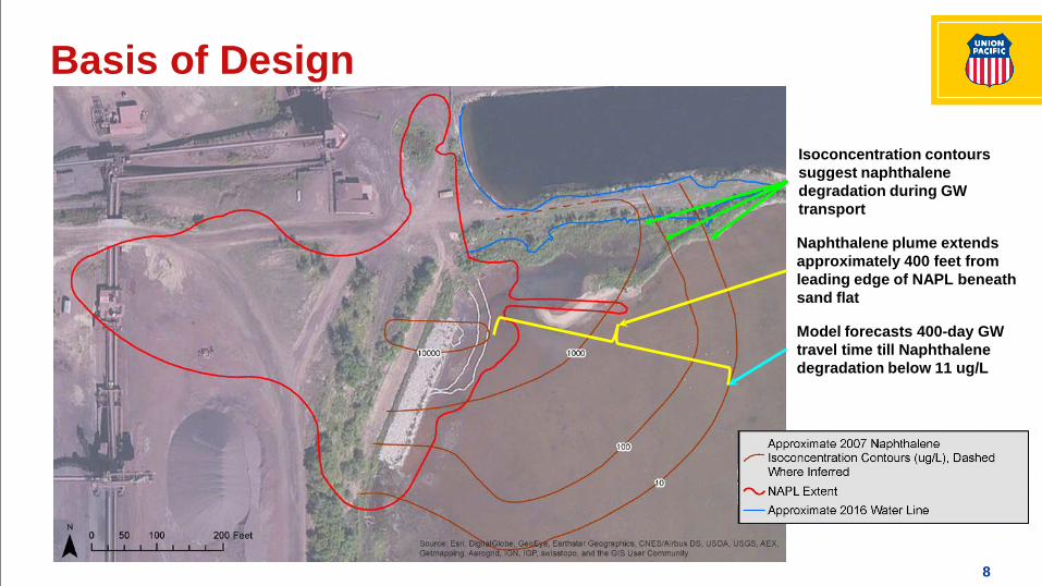
Basis of Design
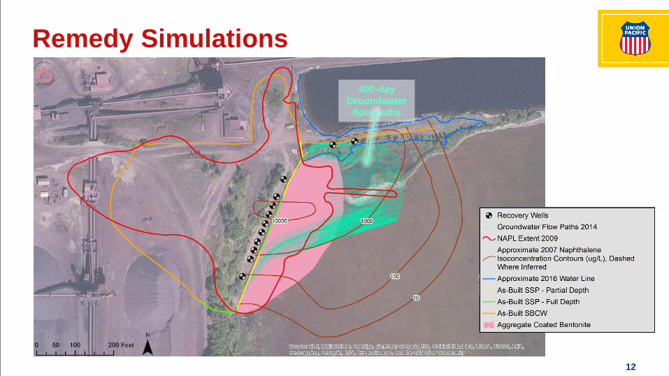
Naphthalene plume extends approximately 400 feet from leading edge of NAPL beneath sand flat
Isoconcentration contours suggest naphthalene degradation during GW transport
Model forecasts 400-day GW travel time till Naphthalene degradation below 11 ug/L
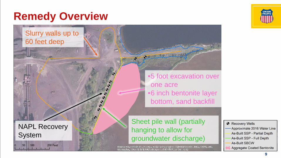
9
Remedy OverviewSlurry walls up to 60 feet deep
NAPL Recovery System
Sheet pile wall (partially hanging to allow for groundwater discharge)
•5 foot excavation over one acre
•6 inch bentonite layer bottom, sand backfill
10
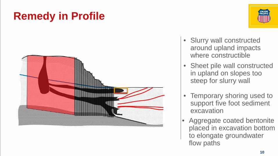
Remedy in Profile
• Slurry wall constructed around upland impacts where constructible
• Sheet pile wall constructed in upland on slopes too steep for slurry wall
• Temporary shoring used to support five foot sediment excavation
• Aggregate coated bentonite placed in excavation bottom to elongate groundwater flow paths
11
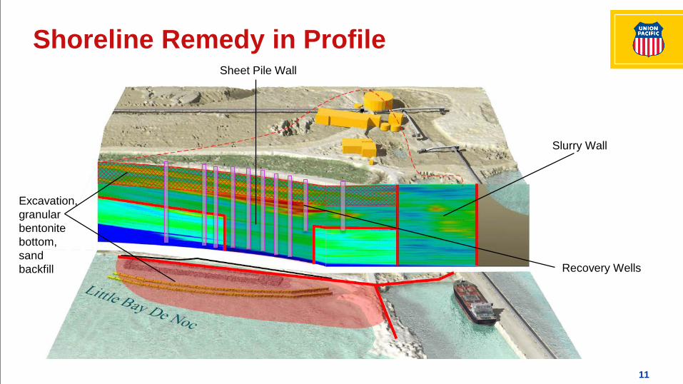
Shoreline Remedy in Profile
Excavation, granular bentonite bottom, sand backfill
Sheet Pile Wall
Slurry Wall
Recovery Wells
12
Remedy Simulations400-day
Groundwater flow paths
13
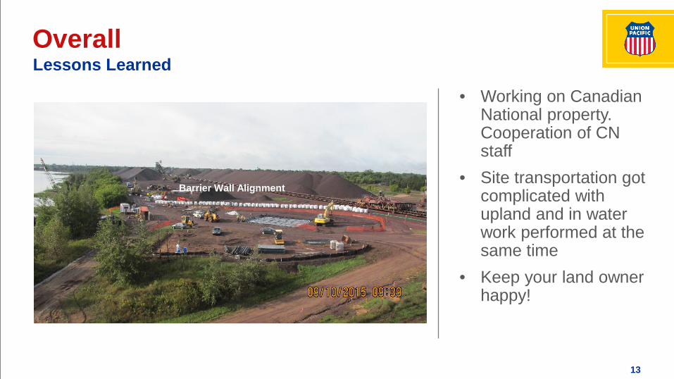
Overall
Barrier Wall Alignment
Lessons Learned
• Working on Canadian National property. Cooperation of CN staff
• Site transportation got complicated with upland and in water work performed at the same time
• Keep your land owner happy!
14
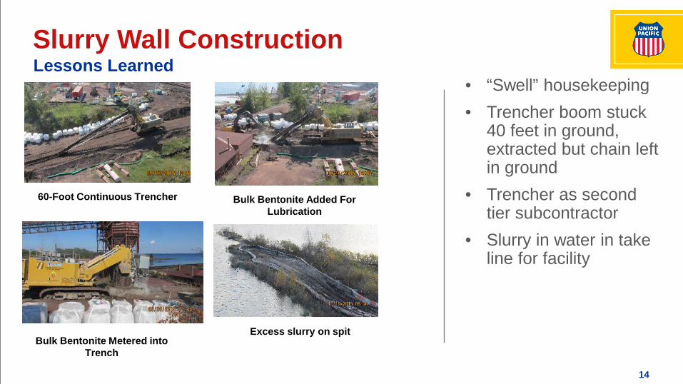
Slurry Wall Construction
Barrier Wall Alignment
60-Foot Continuous Trencher Bulk Bentonite Added For Lubrication
Bulk Bentonite Metered into Trench
Excess slurry on spit
Lessons Learned• “Swell” housekeeping• Trencher boom stuck
40 feet in ground, extracted but chain left in ground
• Trencher as second tier subcontractor
• Slurry in water in take line for facility
15
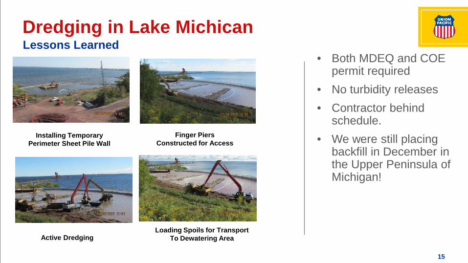
Dredging in Lake Michican
Installing Temporary Perimeter Sheet Pile Wall
Finger Piers Constructed for Access
Active DredgingLoading Spoils for Transport
To Dewatering Area
Lessons Learned• Both MDEQ and COE
permit required• No turbidity releases• Contractor behind
schedule. • We were still placing
backfill in December in the Upper Peninsula of Michigan!

16
Sheet Pile Wall
Sheet Pile Setup on Shoreline Vibratory Hammer Used to Install Sheet Piles
Sheets Extend Above Historic High lake Level
Shoreline Picture
Lessons Learned
• Sheet pile designed as permanent structure. During construction also needed to support 5 foot cut for dredging
• Specification for a secondary seal on interlocks. Contractor offered as adder, not really cost effective option
17
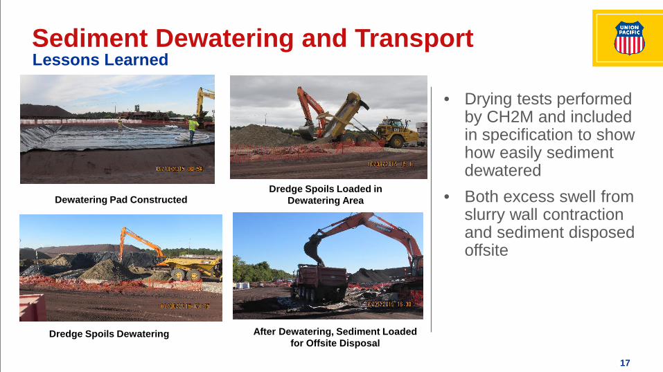
Sediment Dewatering and Transport
Dewatering Pad ConstructedDredge Spoils Loaded in
Dewatering Area
After Dewatering, Sediment Loaded for Offsite Disposal
Dredge Spoils Dewatering
Lessons Learned
• Drying tests performed by CH2M and included in specification to show how easily sediment dewatered
• Both excess swell from slurry wall contraction and sediment disposed offsite
18
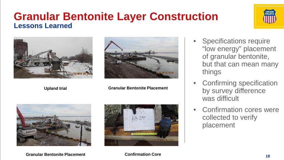
Granular Bentonite Layer Construction
Upland trial Granular Bentonite Placement
Granular Bentonite Placement Confirmation Core
Lessons Learned
• Specifications require “low energy” placement of granular bentonite, but that can mean many things
• Confirming specification by survey difference was difficult
• Confirmation cores were collected to verify placement
19
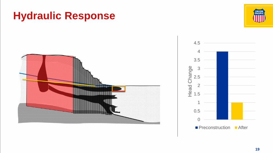
Hydraulic Response
0
0.5
1
1.5
2
2.5
3
3.5
4
4.5
Hea
d C
hang
e
Preconstruction After
20
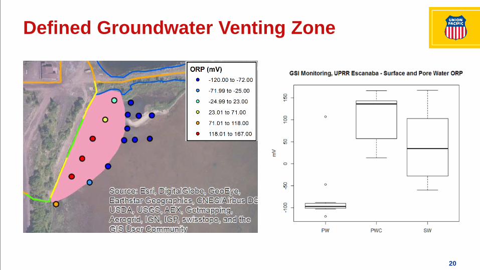
Defined Groundwater Venting Zone

21
Spring 2016 Naphthalene Results
• Sampled sediment pore water at GSI interface
• Naphthalene concentration results:– Low over cap– High at edge of cap– Decreasing along GW flow
path after cap
• Naphthalene > GSI– 400 feet preconstruction– <100 feet 6 months after– Results already exceed
groundwater model travel time predictions
22
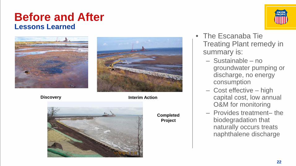
Before and After
Discovery Interim Action
Completed Project
Lessons Learned• The Escanaba Tie
Treating Plant remedy in summary is:– Sustainable – no
groundwater pumping or discharge, no energy consumption
– Cost effective – high capital cost, low annual O&M for monitoring
– Provides treatment– the biodegradation that naturally occurs treats naphthalene discharge


