Lecture 13
High Rate Settlers
SPRING 2014
Assist. Prof. A. Evren Tugtas
ENVE 301
Environmental Engineering Unit Operations
High Rate Clarification
Refers to all processes that can be loaded at higher
rate than its typically used in conventional clarifiers.
Principal types of units used:
Tube settlers
Plate settlers
Solids contact units
Sludge blanket clarification
Dissolved air floatation
Contact clarification
2

Inclined Settlers
Equal flow distribution in each channel is very
important
3
Ref: American Water Works Association. Water Quality and Treatment: A handbook of
community water supplies. 5th ed. McGraw Hill, 1999

Inclined Settlers
Counter Current Settlers:
Suspension is fed below the settling modules
Suspension flow is up the channels
Solids settle onto the lower surface in each channel
If the angle is sufficient, solids move down the surface
counter to the flow of liquid
Tube settlers are mostly counter current
4

Inclined Settlers
Cocurrent Settlers:
Suspension is fed above the settling modules
Settled solids move down the surface in the same
direction as the liquid
Cross Flow Settlers:
Suspension flows horizontally between the inclined
surfaces
Settled solids move downwards
Resuspension of settled solids is a less concern compared
to that of Countercurrent or cocurrent settlers
5
High Rate Settlers
High rate settler units (tubes, plates etc) achieve
effective settling in detention times less than 20
min (conventional sedimentation tank 2 h)
Existing sedimentation tanks can be modified to
include such units
6
Tube Settlers
Theoretically shallow basin should be effective in
terms of settling efficiency (short settling distance)
Shallow, parallel tubes increase surface area and
reduce settling distance
Tubes are placed at 50 - 60 efficient settling,
self cleaning of surfaces occur
Typical separation distance between inclined
surfaces = 50 mm, with an inclined length of 1-2m
7
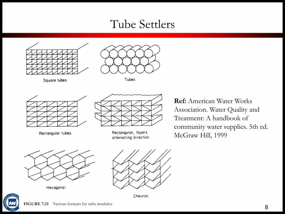
Tube Settlers
8
Ref: American Water Works
Association. Water Quality and
Treatment: A handbook of
community water supplies. 5th ed.
McGraw Hill, 1999

9

Inclined Settlers
Counter Current Settlers:
Suspension is fed below the settling modules
Suspension flow is up the channels
Solids settle onto the lower surface in each channel
If the angle is sufficient, solids move down the surface
counter to the flow of liquid
Tube settlers are mostly counter current
10
Tube Settlers – Desing Criteria
Designed based on the total projected surface
area of tubes
Surface loading rate of 1.2 m/h for aluminum,
iron based coagulants (range from 1-2 m/h)
Inlet conditions:
Turbulence causes uneven flow distibution to the
tubes
Sludge falling from the tubes must be able to settle to
the tank bottom (high velocities cause high shear)
11

Tube Settlers – Desing Criteria
Inlet conditions:
To avoid turbulence stilling zone of 25% of the total basin area
should be left (stilling zone: distance between the inlet and the
settlers)
A minimum depth of 3 m should be left below the tubes
Effluent Design:
A clear space of 2-3 m above the tubes must be provide
Launders should be spaced less than 1.5m centers
Solids removal:
Solids can be removed with same type of equipment as used in
the conventional sedimentation unit
12

Plate Settlers
13
Ref: American Water Works Association. Water Quality and Treatment: A handbook of
community water supplies. 5th ed. McGraw Hill, 1999
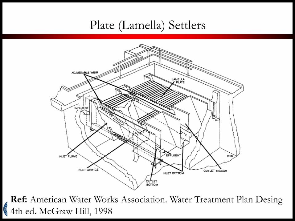
Plate (Lamella) Settlers
14
Ref: American Water Works Association. Water Treatment Plan Desing
4th ed. McGraw Hill, 1998
Plate (Lamella) Settlers
Typical Loading rates range from 0.7-1.7 m/h, which corresponds to
5-15 m/h for overall basin loading
Cocurrent flow is applied
Inlet distribution is critical
Launders should be placed on the order of 1.8 m
Submerged orifices should be designed to create headloss– to enable
good flow distribution
Orifice velocity of 46-76 cm/s is adequate
Chain and flight or bottom tract units are generally used for sludge
collection
15

16
Courtesy of
Prof. Dr. A. M. Saatçı

17
Ref: Davis M.L. Water and
Wastewater Treatment: Design
Principles and Practice. 2010.
McGrawHill
Upflow Clarifiers (Solids Contact Units)
Flocculation and sedimentation takes place in a
single unit
Some units operate with chemical feed directly into
the pipe
Upflow solids contact clarifiers combine; mixing,
coagulation, flocculation, liquid/solid separation,
sludge removal in a single tank
Two types of solids contact units
Premix
Premix-recirculation 18

Upflow Clarifiers
Types of Upflow Clarifiers
Solids Contact
Sludge Blanket
Two types of solids contact units
Premix
Premix-recirculation
19
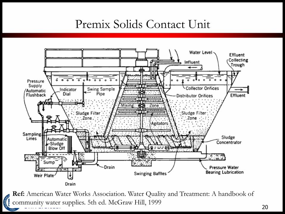
Premix Solids Contact Unit
20
Ref: American Water Works Association. Water Quality and Treatment: A handbook of
community water supplies. 5th ed. McGraw Hill, 1999
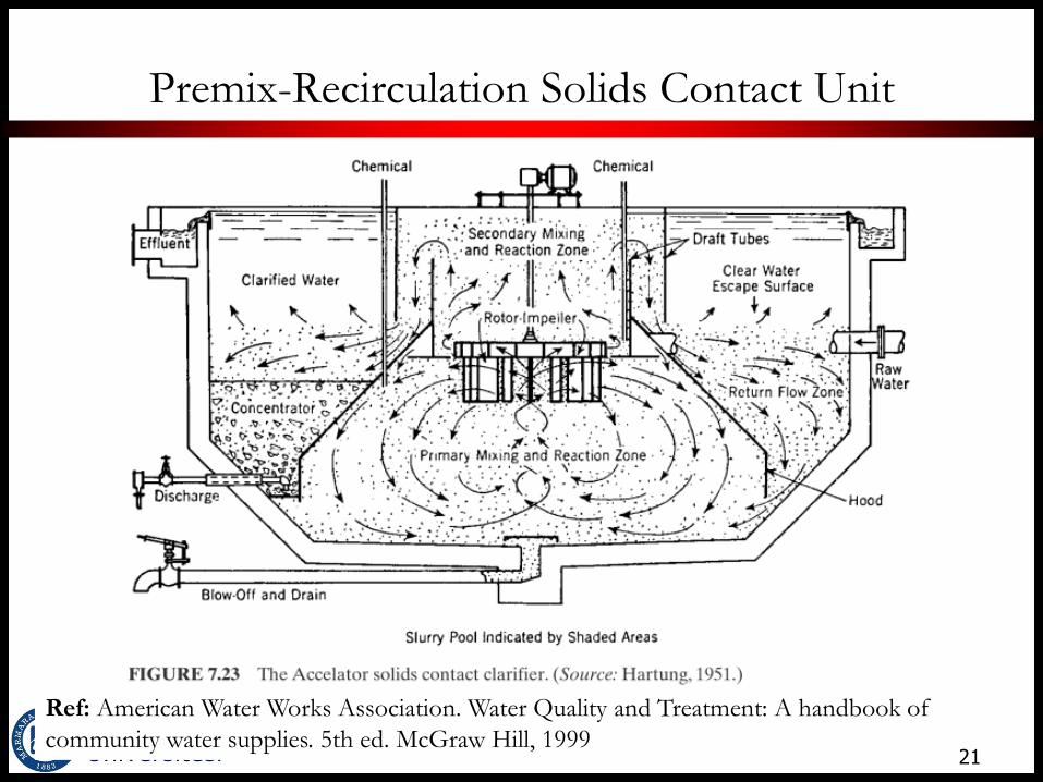
Premix-Recirculation Solids Contact Unit
21
Ref: American Water Works Association. Water Quality and Treatment: A handbook of
community water supplies. 5th ed. McGraw Hill, 1999

Solids Contact Units – Design Criteria
Surface loading rates: 1.2-3.7 m/h
Flocculation contact zone: 30 min detention time
To provide good flow distribution units are
circular and have a diameter up to 46 m
Launders designed with low loading rates
(248L/min/m). Spacing is about 4.6-6.1m
Rakes are used for solids removal
22
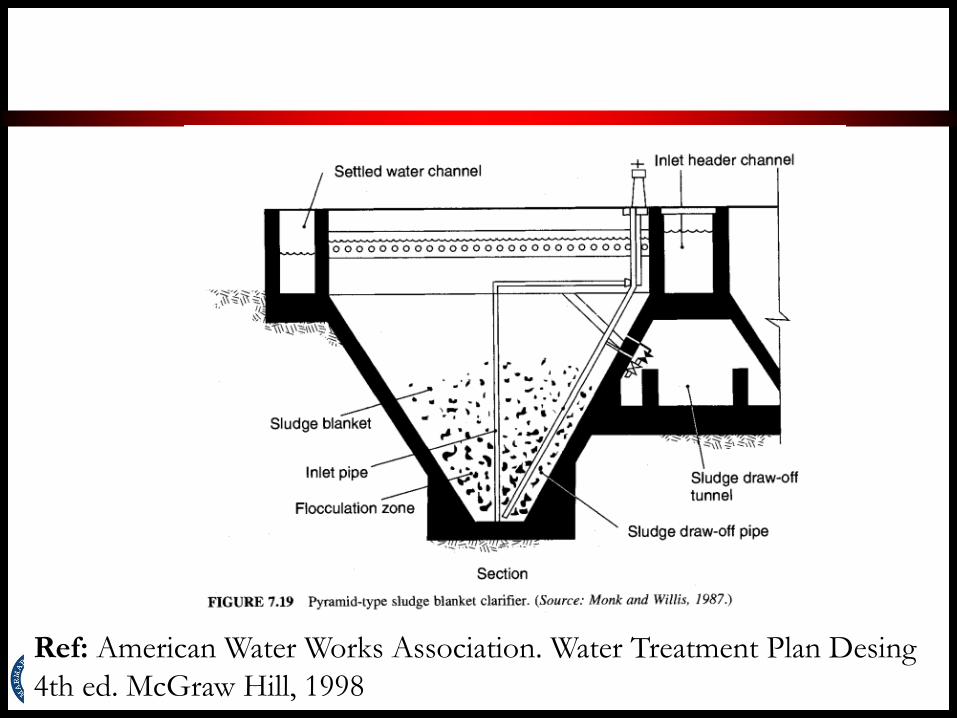
Sludge Blanket Clarification
Variation of solids contact clarifier
Flocculated water flows up through a blanket of
previously formed solids
Blanket depth should be 0.5-1m
When blanket depth reaches the design depth,
portion of the blanket next to the hopper settles
into the hopper.
Sludge is periodically removed from the hopper by
gravity
23
24
Ref: American Water Works Association. Water Treatment Plan Desing
4th ed. McGraw Hill, 1998

Courtesy of Prof. Dr. A. M. Saatçı
25
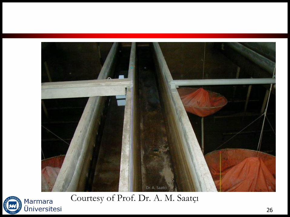
26
Courtesy of Prof. Dr. A. M. Saatçı

27 Prof. Dr. A. M. Saatçı, lecture notes
Problem session

29
Ref: Reynolds, T. D., and P. A. Richards. Unit Operations and Processes in Environmental
Engineering. 2nd ed. Boston, MA: PWS Publishing Company, 1996.


