S
. O. Masebinu1, A. Aboyade2 and E. Muzenda3
Abstract— Biogas, a renewable energy, can be captured,
upgraded and used to fuel a vehicle as an alternative to fossil fuel,
thus, reducing greenhouse gas emission. Biogas is environmentally
hazardous if emitted directly into the environment. Increasing
demand for bio-methane to be used as vehicular fuel has called for
efficient use of waste and technology that is optimal yet economical.
Biogas in its raw state contains impurities that reduce its heating
value to be used directly as fuel, hence, a need to enhance it by
upgrading to bio-methane. Several techniques exist for upgrading
biogas to bio-methane. This paper present four upgrading techniques;
absorption, adsorption, membrane and cryogenic techniques, a brief
theoretical background, advantages and operational issues associated
with each technique.
Keywords—Biogas, Enrichment, Vehicular fuel and
Environment
I. INTRODUCTION
HE development of renewable energy has attracted a
great deal of interest not only because of the steady rise in
oil prices, but also because of the limit of fossil fuel reserves
[1]. Bio-methane, an enriched biogas, is an important
renewable fuel; it is environmentally friendly, clean, cheap
and versatile [2]. Biogas is typically produced by the
decomposition of organic matters in the absence of oxygen.
Raw biogas comprises mainly methane and carbon dioxide,
and smaller traces of the pollutant hydrogen sulphide, nitrogen
and water vapour. The biogas heating power is proportional to
the methane concentration. However, the proportion of
methane to carbon dioxide in biogas varies to some degree
depending on the composition of the substrate [3], digestion
systems, temperature, and retention time [4]. Raw biogas
contains about 50–65% methane (CH4), 30–45% carbon
dioxide (CO2), traces of hydrogen sulphide and fractions of
water vapour [5]. Raw biogas with methane content of 50%
has a heating value of 21MJ/m3 while upgrade biogas with
methane content of 100% has a heating value of 33.41MJ/m3
which makes upgraded biogas better suited for use in higher
value applications such as vehicular fuels [4], [6]. Natural gas
S. O. Masebinu is with the department of Chemical Engineering,
University of Johannesburg, Doornfontein, South Africa
([email protected]) A. Aboyade is a Post-Doctoral Research Fellow at the department of
Chemical Engineering, Environmental & Process Systems Engineering,
University of Cape Town, Private bag X3, Rondebosh 7701, South Africa ([email protected])
E. Muzenda is a Professor of Chemical Engineering. He is the head of
Environmental and Process Systems Engineering Research Unit, Faculty of
Engineering and the Built Environment, University of Johannesburg,
Doornfontein, P O Box 17011, 2028, South Africa (Email:
[email protected]).*Corresponding author.
has 75-98% methane with small percentages of ethane, butane,
propane. It is possible to improve the quality of biogas by
enriching its methane content up to the natural gas level.
Current technologies for upgrading biogas are often a multi-
stage process. The removal of hydrogen sulphide, carbon
dioxide and water from biogas often require different
processes and this adds to the cost of biogas upgrading.
However, the upgrading technology is rapidly evolving and
becoming cheaper [7]. The gas upgrading processes for
removal of carbon dioxide from gaseous process stream can
generally be classified into: absorption, adsorption, cryogenic
and membrane.
In sustaining the environment, all waste to energy
conversion processes must be carried out in a safe and
efficient manner. This is to ensure that human being and the
ecosystem are protected from the negative effect of any of
such conversion process. Issues such as the selection of an
optimal technique for biogas upgrading, the environmental
impact, efficiency, operational condition, scalability and cost
implication of the chosen technique all requires critical
assessment. This paper gives an overview of four biogas
upgrading techniques: starting from a brief theoretical
background, to a description of the state-of-the-art in terms of
research and industrial applications, and operational issues
associated with each technique.
II. BIOGAS ENVIRONMENTAL IMPACT
Biogas is considered an interesting fuel alternative from an
environmental perspective because biogas is an
environmentally hazardous by-product to traditional waste
treatment methods such as landfilling of organic waste. When
biogas is released to the atmosphere, the methane content, a
greenhouse gas, has about 20 times the global warming
potential of carbon dioxide [8]. Methane, hydrogen sulphide
and siloxane present in biogas needs to be reduced to less
harmful substances before been released to the environment
thus the need to upgrade biogas for use as fuel. After
enrichment, bio-methane when used as fuel in vehicles, offer
some positive properties regarding emissions. Bio-methane
creates lesser emissions when compared to other fossil fuel
source like petrol and diesel. The combustion of 1kg of any
hydrocarbon fuel theoretically emits about 2.7kg of carbon
dioxide [9]. The fumes from petrol and diesel contain benzene
and toluene which are not present in fumes from biogas [10].
Furthermore, bio-methane has lower emission of carbon
monoxide, hydrocarbons, carbon dioxide, particulates and
sulphide compounds as compared to diesel, petrol and natural
Enrichment of Biogas for Use as Vehicular Fuel:
A Review of the Upgrading Techniques
S. O. Masebinu, A. Aboyade, and E. Muzenda
T
Int'l Journal of Research in Chemical, Metallurgical and Civil Engg. (IJRCMCE) Vol. 1, Issue 1(2014) ISSN 2349-1442 EISSN 2349-1450
http://dx.doi.org/10.15242/ IJRCMCE.E1113552 89
gas which is valid for both light and heavy duty vehicle [10],
[11].
For bio-methane to be used as fuel for internal combustion
engines, it has been recommended a methane concentration
greater than 90% [5]. There is currently only one standard
adopted within the European Union (EU) member state for the
use of biogas as a transport fuel. Sweden has a published
standard - SS 15 54 38: “Motor fuels– biogas as fuel for high-
speed Otto engines” [12]. The standard deals with specific
characteristics relevant to the use and storage of biogas
produced by anaerobic digestion for use as a motor fuel. It
does not cover fuel which might be mixed with other
compounds, e.g. hydrogen, propane, etc. Consequently the
standard reflects a fuel with a high methane number [12].
Table I below present the specific characteristics of enriched
Swedish biogas SS15 5438 [12].
III. EFFECT OF IMPURITIES IN BIOGAS ON COMBUSTION
ENGINE
The impurities in biogas not only reduces the heating value
of biogas it also causes damage to internal combustion engine.
Carbon dioxide, hydrogen sulphide, water vapour, oxide of
nitrogen and siloxane are the impurities in biogas that must be
removed. Table II gives the effect of these impurities in
internal combustion engine [13].
TABLE I
CHARACTERISTICS OF ENRICHED SWEDISH BIOGAS SS15 54 38 FOR USE AS VEHICULAR FUEL [12]
Property Units Requirement
Type A
Requirement
Type B
Wobbe Index MJ/m3 44.7-46.4 43.9-47.3 Methane (Volume at 273K, 101.3KPa) % 97±1 97±2
Motor octane number 130 130
Dew point at highest storage pressure t=lowest monthly daily average temp.
0C t-5 t-5
Water content mg/m3 32 32
CO2+O2+N2 by vol. max of which O2 max
% %
4.0 1.0
5.0 1.0
Total sulphur mg/m3 23 23 Total nitrogen compound calculated as NH3 mg/m3 20 20
TABLE II
THE EFFECT OF BIO-GAS IMPURITIES WHEN USED AS FUEL ON INTERNAL COMBUSTION ENGINE [13]
Component Content Effect
Carbon dioxide 25-30% Lowers the heating value
Increases the methane number & the anti-knock properties of engines
Causes corrosion (low concentrated carbon acid) if the gas is wet
Damage alkali fuel Hydrogen
sulphide
0-0.5% by vol. Corrosive effect in equipment and piping system (stress corrosion), many
manufacturer of engines therefore set an upper limit of 0.05 by vol. %
Sulphur dioxide emissions after burners or hydrogen sulphide emission with
imperfect combustion – upper limit 0.1 by vol. %
Spoils catalyst Ammonia 0-0.05% by vol. NOx emissions after burners damage fuel cells
Increases the anti-knock properties of engines
Water vapour 1-5% by vol. Causes corrosion of equipment & piping systems
Condensates damage instrument & plants
Risk of freezing of piping system and nozzles Dust >5µm Block nozzles and fuel cells
Nitrogen 0.5% by vol. Lowers the heating value
Increase the anti-knock properties of engines
Siloxane 0-50mg/m3 Act like an abrasive and damage engines
IV. BIOGAS UPGRADING TECHNOLOGIES
The research into biogas enrichment can be divided into
two stages, namely research in the laboratory conditions and
research in operative conditions. The laboratory research is
used for analysis of existing techniques, development of new
technologies and prototype development. These are tested in
operative conditions, if successful, they are optimized for
industrial operation [14]. Upgrading adds to cost of biogas
production. It is therefore important to have an optimized
upgrading process in terms of low energy and material
consumption with high efficiency giving high methane content
in the upgraded gas. It is also very important to minimize, or if
possible avoid, emissions of methane from the upgrading
process. This means that the methane content in the reject gas,
and impurities absorbed in any other stream leaving the
upgrading plant should be reduced to less harmful product and
(or) minimised [15].
Both the laboratory research and optimized industrial
application requires two processes; biogas cleaning and biogas
upgrading which can be referred to as biogas enrichment. The
cleaning of the biogas consists of removal of corrosive
products, mainly hydrogen sulphide, water and particles while
the upgrading consists of removal of carbon dioxide to
increase the energy level of the gas [10]. The common
technique for removal of carbon dioxide can also remove other
acid gases, hydrogen sulphide and trace of nitrogen from
biogas to an extent. Hydrogen sulphide, carbon dioxide and
sulphur dioxide are termed as acid gases since they dissociate
to form a weak acidic solution when they come into contact
with water or an aqueous medium [16]. In spite of this, it is
Int'l Journal of Research in Chemical, Metallurgical and Civil Engg. (IJRCMCE) Vol. 1, Issue 1(2014) ISSN 2349-1442 EISSN 2349-1450
http://dx.doi.org/10.15242/ IJRCMCE.E1113552 90
often important to pre-separate some components like
hydrogen sulphide if present in high level from biogas before
been upgraded to bio-methane since these acidic gases can
cause operational problems in the upgrading plant [10]. Hence
it is necessary to briefly examine the cleaning of biogas after
which the upgrading techniques will be discussed.
V. BIOGAS CLEANING
A. Removal of hydrogen sulphide
The removal of hydrogen sulphide could start from the
digester by the addition of iron chloride to the digester slurry
to precipitate out as iron sulphide and be removed together
with the digestate. Hydrogen sulphide can be removed from
biogas by adsorption on activated carbon. The rate of reaction
can be catalysed by doping the pore of the activated carbon
with potassium iodide, potassium carbonate (K2CO3) or zinc
oxide [15]. The doping with zinc oxide it most preferred,
though expensive, in its ability to removed hydrogen sulphide
to less than 1ppm in biogas for use as vehicular fuel [15].
Horikawa, et. al. 2004, used iron-chelated solution catalysed
by ferric ethylenediamine tetraacetic acid (Fe/EDTA) for
removal hydrogen sulphide only from raw biogas. The process
of chemical absorption of hydrogen sulphide into iron-
chelated solutions offers a high efficiency and selectivity with
low consumption of chemical because iron-chelated solutions
function as a pseudo-catalyst that can be regenerated [7]. The
Fe/EDTA converts hydrogen sulphide into elemental Sulphur.
In the iron chelated based process, the sulphur produced is
easily recoverable from the slurry by sedimentation or
filtration operations and the whole process can be carried out
at ambient temperature. With the selective removal of
hydrogen sulphide, the biogas is highly concentrated with only
carbon dioxide as impurity which can be scrubbed using
amine solutions.
B. Removal of water and other impurities
Water can be removed from biogas by cooling,
compression, adsorption using silicon dioxide (SiO2) and
activated carbon. By increasing the pressure or decreasing the
temperature, water will condensate from biogas and can
therefore be removed.
Particles in biogas can be removed by passing biogas over
mechanical filters. Nitrogen and oxygen can be removed by
adsorption with activated carbon, carbon molecular sieve or
membrane [17]. No separate system is required for the
removal of ammonia as it can be removed during gas drying or
during biogas upgrading process. Siloxane can be removed
by cooling the gas, by adsorption on activated carbon, activated aluminium or silica gel, or by absorption in liquid mixtures of hydrocarbons. Siloxane can also be removed whilst separating hydrogen sulphide during the cleaning process [15].
VI. UPGRADING TECHNIQUES
A. Absorption
Absorption is a diffusional operation in which some
components of the gas phase are absorbed by the liquid they
are in contact with. The region separating the two phases is
called the interfacial region [18]. Stripping is exactly the
reverse of absorption. It is the transfer of component from a
liquid phase in which gas is dissolved to a gas phase.
Absorption is undoubtedly the single most important operation
of gas purification process and is used in a large number of
systems [19]. Absorption and stripping are two process
operations that normally are coupled in order to remove some
minor components, the solute, from an incoming process gas
stream and then recover that same component in more
concentrated form. A carefully selected solvent in which the
solute is selectively soluble is fed to the absorber (or
Scrubber) and the rich solvent is then fed to the stripper,
where the solute is recovered. This separation principle of
absorption is based critically on the solubility of the solute
(gas impurities) in the solvent. If an absorber is to be designed
for efficient and economical service, it is critical to select the
proper solvent whose attributes include availability, cost
stability, volatility and non-hazardous [20]. In an upgrading
plant using this technique the raw biogas is intensively
contacted with a liquid within a scrubbing column filled with a
plastic packing in other to increase the contact area between
the phases. Because the impurities to be removed from the
biogas are far more soluble in the liquid scrubbing solution
than methane, they are removed from the biogas stream after
which the methane rich biogas leaves the scrubbing column
and the impurities are collected at the base with the scrubbing
liquid. In order to maintain absorption performance, the
scrubbing liquid has to be replaced by fresh liquid or
regenerated in a separated step (desorption or regeneration
step) [21]. There are two type of absorption processes;
physical absorption process and chemical absorption process.
The reaction of the solvent to the solute determines what type
of absorption has taken place.
1. Theoretical back ground and research
Physical absorption
Physical absorption process is based critically on the
solubility of the solute (gas impurities) in the solvent.
Pressurised gas scrubbing using water as the absorbent is a
physical absorption process. Other solvent used in the process
are polyethylene glycol-dimethyl ether (PEG-DME) e.g the
genosorb 1753 solvent, otherwise known as selexol, and
propylene carbonate [22], [23] which are organic solvents.
The absorption of carbon dioxide and methane into water is
described by Henry law, as in (1), which describes the
relationship between the partial pressure of a gas and the
concentration of the gas in a liquid in contact with the gas
[24].
( ) ( ) ( ) (1)
In (1), CA is the concentration of A in the liquid-phase, KH
is Henry's constant and PA is the partial pressure of A. The
Henry constant at 25°C (KH) for carbon dioxide is 3.4*10-2
M/atm and for methane 1.3*10-3
M/atm, resulting in a
solubility for carbon dioxide that is approximately 26 times
higher than for methane [24], [25]. The value of Henry‟s
constant for a specific gas is only valid at one specific
Int'l Journal of Research in Chemical, Metallurgical and Civil Engg. (IJRCMCE) Vol. 1, Issue 1(2014) ISSN 2349-1442 EISSN 2349-1450
http://dx.doi.org/10.15242/ IJRCMCE.E1113552 91

temperature [24]. When the temperature is increased, the
solubility usually decreases and vice versa [24]. The amount
of water needed to remove a certain amount of carbon dioxide
depends on the design of the column, the required carbon
dioxide concentration in the upgraded biogas and the
solubility of carbon dioxide in a certain volume of water
(determined by the pressure and the temperature) [25].
Solubility of carbon dioxide and hydrogen sulphide in water as
compared to methane as well as the low cost of water has
made the water scrubbing technique the simplest for biogas
upgrading in some countries allowing for 98% methane purity
[26]. With a specific design and a specified carbon dioxide
concentration in the upgraded biogas, the water flow rate and
the gas composition will be determined by the solubility of
carbon dioxide in water [25]. Equation (2) and (3) gives the
water flow rate required to remove carbon dioxide from biogas
[25].
( ⁄ ) ( )( ⁄ )
( )( ) (2)
( ⁄ ) ( ⁄ )
( ) (3)
Where is the required water flow, is the molar
flow of carbon dioxide that shall be removed and is the
solubility of carbon dioxide described as the maximum
concentration possible to reach in water. is the total
biogas flow, is the percentage of carbon dioxide in the
raw biogas and is the pressure in the absorption column
and KH is Henry constant.
Virendra et. al 2006, demonstrated biogas purification
using water as a scrubbing agent. The diameter of the scrubber
and packaged height were given as 150mm and 3500mm
respectively. The inlet gas flow rate was varied from 1.0-
3.0m3/h at a constant pressure of 1.0 MPa. The dissolubility of
hydrogen sulphide and carbon dioxide increases with pressure,
so also the saturation pressure, hence when higher pressures
are reached the dissolubility of the components will not
linearly increase with the pressure [7]. It was found that the
percentage carbon dioxide absorption from raw biogas initially
increased when the flow rate vary from 1.0 to 1.5m3/h and
afterwards it decreased continuously. The highest carbon
dioxide absorption observed was 99% at 1.5m3/h gas flow rate
at 1.0 MPa inlet gas pressure. Flooding of the scrubber column
was reported at 1.8m3/h inlet flow rate of the water (Virendra
K. Vijay, 2006).
Boateng and Kwofie, 2009, carried out a feasibility study
on Appolonia biogas plant in Ghana, which uses water as its
scrubbing agent. 95% bio-methane was recorded as the highest
purity the system could deliver operating at 70% efficiency.
The heating value of the raw biogas was 20MJ/m3 and after
upgrading, the heating value rose up to 28.7%MJ/m3. In both
Virendra and Boateng experiments, there was no regeneration
of water laden with carbon dioxide and hydrogen sulphide;
this is not an environmentally friendly practice. Regenerated
water can be fed back into the scrubbing column and used
again. Regeneration is accomplished by de-pressuring or by
stripping with air in a similar column [27]. Stripping with air
is not recommended when high level of hydrogen sulphide are
contained in the biogas since water quickly become
contaminated with elemental sulphur which causes operational
problem and blocking of column [22] , [27].
Chemical absorption
Chemical absorption process is based on the reactivity of
the chemical reagent used as absorbent to chemically react
with the carbon dioxide molecule and thus removing it from
the biogas feed stream. This is most commonly performed
using a solution of amines (molecules with carbon and
nitrogen), with the reaction product being either in the
molecular or ion form [25]. Chemical scrubbing has an
advantage over physical scrubbing in its capacity to absorb
more carbon dioxide [22]. Alkaline and alkanolamine are
among the popular reagents for practical applications of
carbon dioxide and hydrogen sulphide absorption [28]. The
aqueous solutions include sodium hydroxide, calcium
hydroxide and potassium hydroxide. The types of amine
compounds used are: mono-ethanolamine (MEA), di-methyl
ethanolamine (DMEA), di-ethanol amine (DEA), deglycol
amine (DGA) and diisopropanol amine (DIPA) [29]. Recently,
the most common amine system used industrially today is a
mixture of MDEA and piperazine (PZ) often termed activated
MDEA (aMDEA) [25]. In the design of an amine based
absorption scrubber, two design approaches are used; the
equilibrium based approach and the rate base approach. The
equilibrium base approach is suitable for non-reactive system
while the rate base approach is suitable for reactive system,
although most researchers use the rate base approach because
of its simplicity and accuracy [30]. Amine based absorption
system is a selective process, in processes for total gas
impurities removal, treated gas quality is completely
determined by phase equilibrium provided the column
contains enough trays or packed depth. This is not the case in
selective treating. The extent to which each gas impurities are
removed is related directly to its mass transfer rates as well as
to the mass transfer rates of each of the other absorbing acid-
gas species [31]. The reaction of hydrogen sulphide with
amines is essentially instantaneous and that of carbon dioxide
with amine is relatively slower [31]. Therefore, for amine,
hydrogen sulphide and carbon dioxide absorption in a packed
column, mass transfer is not limited by chemical reaction but
by the mechanical diffusion or mixing of the gas with the
liquid and by the absorbing capacity of the amine [32].
Cekanova et. al. 2011, carried out an experimental
laboratory research on biogas enrichment to bio-methane
using chemical adsorption for removal of hydrogen sulphide
and chemical absorption for removal of carbon dioxide in a
scrubbing unit. Amine solution was used as the chemical
solvent for scrubbing in the enrichment design. Hydrogen
sulphide was removed with chemical adsorption method
through the system of filters with activated carbon. Methyl-
diethanolamine (MDEA) and mono-ethanolamine (MEA)
solutions were used as the solvent for removal of carbon
dioxide. The result of the two experiments showed that using
10% mono-ethanolamine as an absorbent resulted in 100%
carbon dioxide removal in first minute of the reaction. 100%
Int'l Journal of Research in Chemical, Metallurgical and Civil Engg. (IJRCMCE) Vol. 1, Issue 1(2014) ISSN 2349-1442 EISSN 2349-1450
http://dx.doi.org/10.15242/ IJRCMCE.E1113552 92
removal was only achieved before the amine solution
approaches carbon dioxide saturation, which took about 7
minutes. The reaction was exothermic and loss of the
absorbent was noticed due to evapouration. Huertas et. al.
2011 used mono-ethanolamine (MEA) as the scrubbing liquid
in his experiment. He reported 7.5% effectiveness of mono-
ethanolamine if hydrogen sulphide is the main impurity to be
removed and above 50% if carbon dioxide is the main
impurity to be removed using mono-ethanolamine. Also the
efficiency of the amine reduced after regeneration. He
therefore recommended the removal of hydrogen sulphide
before amine scrubbing is used for upgrading of biogas.
2. Advantages of absorption
i. Physical absorption requires less material.
ii. If impurities concentration is low they can be removed to
an extent by the process [8].
iii. Biomethane stream produced by the process can be
directly utilized at delivery pressure but must be
compressed for use as vehicular fuel.
iv. Complete carbon dioxide removal using amine is
achievable.
v. The process is highly efficient at optimal operating
condition [8].
vi. It is a proven technology.
3. Operational problems
i. Alkali aqueous solutions are not regenerable, therefore
large volume of the solvent is required
ii. Alkanolamines are regenerable but at high temperature
with loss of amine after regeneration.
iii. Fluctuation in efficiency of the absorbent due to refilling
of lost amine
iv. Corrosion of scrubbing column.
v. Microbial growth in the column when water is used as
absorbent.
vi. Foaming can also occur when the flow rate of absorbent
is not properly regulated and when impurities are present
in water.
vii. Disposal of waste water [8].
B. Adsorption
Adsorption is the selective concentration of one or more
components of a gas at the surface of a micro-porous solid,
preferably one with a large surface area per unit mass [19],
[33]. The mixture of adsorbed component, in this case raw
biogas, is called the adsorbate and the micro-porous solid,
which could be an activated carbon or zeolite, is the adsorbent.
Pressure swing adsorption and temperature swing adsorption
are two types of adsorption processes [33] but of importance is
the pressure swing adsorption. When the regeneration of the
adsorbent is performed by reducing the total pressure of the
system, the process is termed pressure swing adsorption
(PSA), the total pressure of the system “swings” between high
pressure in feed and low pressure in regeneration [33].
Pressure swing adsorption (PSA) is a dry method used to
separate gases via physical properties [25]. With the PSA
technique, carbon dioxide is separated from the biogas by
adsorption on a surface under elevated pressure. The
adsorbing material is regenerated by a sequential decrease in
pressure because the attractive forces holding the adsorbate on
the adsorbent are weaker than those of the chemical bonds and
the adsorbate can generally be released before the column is
reloaded again, hence the name of the technique [34]. The
adsorption of hydrogen sulphide is normally irreversible in the
adsorbents and thus a process to eliminate this gas should be
placed before the PSA [35], [36]. For a continuous production,
several columns are needed as they will be closed and opened
consecutively. The gas pressure released from one vessel is
subsequently used by the others [34]. PSA unit characteristics
include feeding pressure, purging pressure, adsorbent, cycle
time and column interconnectedness [25].
1. Theoretical back ground and research
The choice of adsorbent, the bed material which selectively
adsorbs carbon dioxide from the raw gas stream, is crucial for
the function of the PSA unit [25]. The common adsorbent
materials used are activated carbon, natural and synthetic
zeolites, silica gels, carbon molecular sieves (CMS) and metal
organic framework, a new type of adsorbent material [25],
[33]. The molecular size of methane and carbon dioxide are
3.8Å and 3.4Å respectively [36]. Therefore an adsorbent with
pore matrix of 3.7Å when selected will retain most carbon
dioxide until it is saturated whilst methane is not allowed to
enter into the material but passes through interstitial spaces.
Generally, adsorbents are one of two types; equilibrium
adsorbents (activated carbons, zeolites) which have the
capacity to adsorb much more carbon dioxide than methane,
while kinetic adsorbents (CMS) have micro-pores which the
small carbon dioxide molecules can penetrate faster than the
hydrocarbons which thus pass the column bed unrestrained
[25]. The correlation between gas adsorption and pressure for
two adsorbent materials is shown by the isotherm diagram in
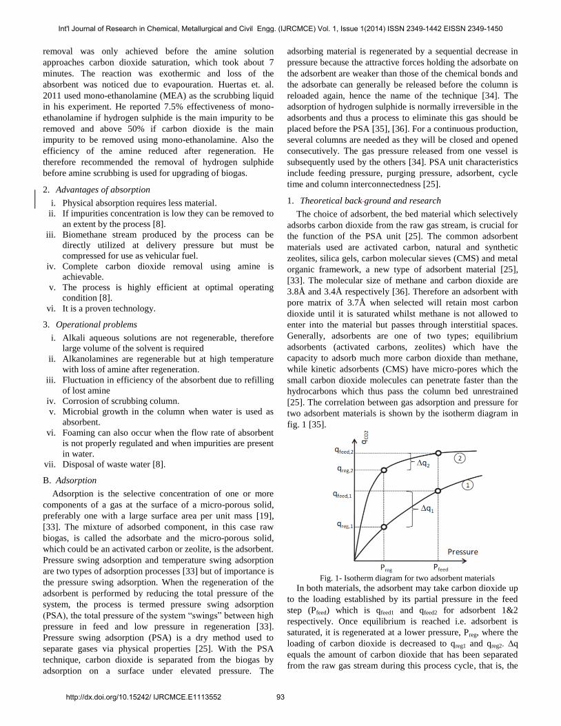
fig. 1 [35].
Fig. 1- Isotherm diagram for two adsorbent materials
In both materials, the adsorbent may take carbon dioxide up
to the loading established by its partial pressure in the feed
step (Pfeed) which is qfeed1 and qfeed2 for adsorbent 1&2
respectively. Once equilibrium is reached i.e. adsorbent is
saturated, it is regenerated at a lower pressure, Preg, where the
loading of carbon dioxide is decreased to qreg1 and qreg2. ∆q
equals the amount of carbon dioxide that has been separated
from the raw gas stream during this process cycle, that is, the
Int'l Journal of Research in Chemical, Metallurgical and Civil Engg. (IJRCMCE) Vol. 1, Issue 1(2014) ISSN 2349-1442 EISSN 2349-1450
http://dx.doi.org/10.15242/ IJRCMCE.E1113552 93
difference between qfeed and qreg. Adsorbent (2) has the
capacity to adsorb much more carbon dioxide at Pfeed but
adsorbent (1) is the preferred choice for this process since ∆q1
is much larger than ∆q2. Therefore, when designing a PSA the
isotherm shape of the adsorbent material should to be known.
A good adsorbent has a nearly linear isotherm, as a curve with
a low steep makes it easy to desorb the carbon dioxide at a
very low pressure and low energy consumption which ensures
an efficient separation process [35].
Cekanova et. al., Horikawa et. al. and Farooq et. al. have all
employed this technique alongside other techniques for biogas
purification though at different experimental conditions.
Grande et. al. 2006, studied the adsorption of carbon dioxide
on zeolite 13X an example of equilibrium adsorbent and
carbon molecular sieve (CMS-3K) an example of kinetic
adsorbent. It was reported that carbon molecular sieve could
produce fuel grade methane with 98% purity from a 55%
methane content raw biogas. For zeolite 13X, the recovery of
methane was not higher than 60%. The kinetic adsorbent
CMS-3K showed a good trade-off between purity and
recovery and also consume less power than zeolite [37].
2. Advantages
i. The process of PSA requires less heat [33].
ii. There is flexibility of design and more than one
absorbent can be used in the process [33], [36].
iii. It is suitable for small to medium scale plants.
iv. PSA technology does not require any water and does not
produce contaminated waste water as well [25].
v. No bacteria contaminant of off-gas [8].
vi. PSA is a dry process and there is no use of liquid
chemical [8].
3. Operational issues
The electricity consumption of a PSA system is high. To
extend the operational life of the plant, hydrogen sulphide
must be removed before biogas enters the adsorption chamber.
Also due to the high operating pressure, cooling system is
required for the compressor.
C. Membrane separation
Membranes are discrete, thin semi-permeable barriers that
selectively separate some compounds from others [38].
Polymeric membranes separate gases by selective permeation
of one or more gaseous components from one side of a
membrane barrier to other side. The membrane does not
operate as a filter, where small molecules are separated from
larges ones through a medium of pores, rather the components
dissolve in the polymer at one surface and are
transported/diffuse across the membrane as the result of a
concentration gradient [19], [38]. The concentration gradient
is maintained by a high partial pressure of the key component
in the gas on one side of the membrane barrier and a low
partial pressure on the other side [19]. Two classes of
membranes are used commercially in gas separation
technology: The first class are glass polymer membranes
which separate gases based on differences in the size of the
gas molecules and the second class are membranes made
either from highly flexible rubbery polymers or ultra-high free
volume glassy substituted polyacetylenes which separate gases
based on difference in the solubility of gas molecules in these
polymers [39]. The commercially viable membranes used for
carbon dioxide removal are polymer based e.g. cellulose
acetate, ployimide, polyamides, polysulfone, poly carbonate
and polyetherimide [38]. Membrane used for biogas upgrading
allows the carbon dioxide to diffuse through it while methane
is retained [25]. This results in enriched biogas that can be
used to fuel a vehicle.
Raw biogas should be cleaned by removing impurities such
as hydrogen sulphide, water, ammonia, siloxane and volatile
organic compound before the biogas upgrading process using
membrane [25]. Research into membrane material is leading
the way for some of these impurities to permeate through the
membrane for example a company called UOP in Illinois,
United State of America designed a cellulose acetate
membrane for bulk removal of hydrogen sulphide at high
pressure. In high concentration of hydrogen sulphide in the
biogas, most polymers tend to have little resistance to
hydrogen sulphide plasticization (softening of the membrane)
and thus limiting the use of membrane if the concentration of
hydrogen sulphide in biogas is not known or the raw biogas
composition fluctuates [38]. Since hydrogen sulphide
permeates through the membrane to some extent, thus
enriched biogas can still contain hydrogen sulphide [25].
1. Theoretical Background and Research Review
A field stream of biogas separated using membrane is split
into two product stream: permeate and retentate. The permeate
is the material that has passed through the membrane and the
retentate is the material that has been rejected by the
membrane [40]. Membrane technology can be applied to
particle-liquid separation, liquid-liquid separation and gases
separation [40]. The potential application of a polymer as a
separation membrane depends upon the selectivity towards the
gas to be separated which determines product purity and
recovery and the permeate flux that determines how efficient
the membrane will be [39]. The accurate design and
optimization of a gas separation system using polymer
membrane depends on the possibility of predicting correctly
the membrane transport properties. The transport of a gas
molecule through a membrane can be expressed as given in
(4) [41].
(4)
In the equation ji denotes the molar flux for gas, Di is the
permeate diffusion coefficient, Ki is the sorption coefficient,
Δpi is the difference in partial pressure between the feed and
permeate side and l is the membrane thickness. The
permeability of a membrane is defined as the product of the
diffusion and sorption coefficient [25]. The membrane
selectivity of two gases „a‟ and „b‟ is defined as the
permeability of gas „a‟ divided by permeability of gas „b‟
which coefficient, sorption or diffusion depends on the type of
material that is used in the membrane [25]. The permeability
decreases with increasing size of the molecule in a glassy
Int'l Journal of Research in Chemical, Metallurgical and Civil Engg. (IJRCMCE) Vol. 1, Issue 1(2014) ISSN 2349-1442 EISSN 2349-1450
http://dx.doi.org/10.15242/ IJRCMCE.E1113552 94
polymer which is commonly used in the membrane for biogas
upgrading since diffusion coefficient is dominating [41].
Miltner et. al. 2008, reported the presence of hydrogen
sulphide, ammonia and water vapour can jeopardize the
membrane material hence, he recommended pre-treatment of
biogas before upgrading. These pre-treatment include the
drying of biogas by cooling and refrigeration method and the
desulphurization over iron oxide. The biogas upgrading plant
in Margarethen lower Austria produces 25kg/h (33Nm3/h)
biomethane using the membrane separation technique.
Varying raw biogas composition of 40-52% vol. methane, 1 to
19ppm hydrogen sulphide is fed into the biogas upgrading
plant which is fully automated. The hydrogen sulphide is
removed separately while the cleaned biogas is upgraded
using the membrane technique. The required quality of
upgraded biogas, >95%vol. methane was satisfied within 5-10
minutes of the process start-up and was constantly delivered
thereafter [42].
2. Advantages of membrane separation technique
The advantages of membrane technique are listed below
[38]
i. Lower capital cost as compared to PSA upgrading
technique.
ii. Operational simplicity and high reliability on upgrade
biogas.
iii. Space optimization and compactness of the design [8].
iv. The technique is environmentally friendly as there is no
waste solvent, permeate gas can be flared or used as fuel
for heat engines.
v. The technique is ideal for remote location once designed
and install.
vi. Absence of moving parts leads to low level mechanical
wear.
vii. Low maintenance level.
viii. It is a dry process and does not require any chemical [8].
3. Operational issue
Exposure to certain solutions and materials causes
membrane blockage or damage [6]. If proper pre-treatment is
not carried out, the presence of hydrogen sulphide will lead to
plasticization of the membrane material thus hampering the
upgrading process. The membrane resistance to breaking due
to the pressure gradient is also an important technical
limitation of this technology since replacement of damage
membrane is expensive [6]. Also there is need for replacement
of the membrane over a specific period of time depending on
the manufacturer‟s specification. Energy consumption of
membrane plant is normally determined by the compressor
requirement [25]. The installed membrane area determines the
operating pressure of the system. If the membrane area is
large, lower pressure is required for the system since lower
flux (permeate flow per membrane area) can be accepted [25]
with reference to (4) above.
D. Cryogenic separation
Cryogenic separation uses the different temperature related
properties of the gas species to separate them from each other
[6]. The process starts with compression of raw biogas to 17-
26bar and then cooled to -260C for removal of hydrogen
sulphide, sulphur dioxide, halogens and siloxane [15]. The raw
biogas is cooled down step wisely to temperature where
carbon dioxide in the gas can be liquefied and separated
through several heat exchangers [6], [15]. Pure carbon dioxide
has a de-sublimation temperature of -78.50C at atmospheric
pressure while methane condenses at -1610C [6]. Carbon
dioxide both sublimate and de-sublimate at atmospheric
pressure i.e. its change state from gas to solid without going
through the liquid state and the opposite (de-sublimate)
without first liquefying. When carbon dioxide in biogas is de-
sublimated it follows that the partial pressure of carbon
dioxide is reduced, therefore the concentration of carbon
dioxide is lowered and a lower temperature will be required to
further de-sublimate the carbon dioxide [6]. Depending on the
temperature of the process different purity can be reached. A
lower temperature results in a higher removal efficiency of
carbon dioxide. However, the presence of methane in the
biogas mixture affects the characteristics of the gas thus
requiring higher pressure and\or lower temperature to
condense carbon dioxide [15]. To avoid freezing and other
problems in cryogenic process, water and hydrogen sulphide
need to be removed [17].
1. Theoretical background
The cryogenic process is basically to generate low
temperature for the de-sublimation of carbon dioxide from
biogas. Cooling can be achieved directly or indirectly. Direct
cooling can be achieved with a combination of equipment
such as compressor, heat exchanger and expansion device just
as used in the refrigeration system for refrigerant cooling. The
indirect cooling is by a heat exchanger with liquid nitrogen to
liquefy the biogas. This indirect cooling is not viable on a
large scale because of the running cost as the introduced
nitrogen is consumed in the process. The two main working
process cycle of the cooling system as used in the cryogenic
biogas upgrading are open loop process cycle and the closed
loop process cycle [43].
Open loop process cycle
Biogas is first compressed to a high pressure causing a rise
in temperature. This creates a good physical property for the
biogas to be heat exchanged with lower temperature heat sink
e.g a refrigeration cycle. After the biogas has been cooled, it is
expanded through a turbine where the pressure and
temperature are decreased. The biogas can this way reach a
low enough temperature to begin the de-sublimation of carbon
dioxide [43].
Closed loop process cycle
Biogas is not compressed before been heat exchanged thus
resulting in lower temperature difference between the biogas
stream and the heat exchanger medium. Since the biogas
temperature is not increased via compression, it is not possible
to use the air as a heat sink therefore a cooling agent e.g.
nitrogen and methane or a mixture of both is required. The
biogas is cooled by the cooling agent before expansion in a
Int'l Journal of Research in Chemical, Metallurgical and Civil Engg. (IJRCMCE) Vol. 1, Issue 1(2014) ISSN 2349-1442 EISSN 2349-1450
http://dx.doi.org/10.15242/ IJRCMCE.E1113552 95
turbine. This decreases both the pressure and temperature
which leads to the sublimation of carbon dioxide [43].
The main part of heat transfer between the biogas and the
cooling media is through convection. A decrease in the
temperature of the biogas will result in increase in viscosity
and density and a decrease in diffusivity within the biogas.
Thus the flow velocity decreases due to increased density [6].
The mass flow of carbon dioxide decreases along the heat
exchanger length as the temperature decreases. The heat
exchangers ability to separate carbon dioxide from biogas is
dependent on the mass flow rate of the incoming biogas, the
concentration of carbon dioxide in the biogas and the
temperature of the incoming cooling media. Also the
geometric properties of the heat exchanger e.g. total heat
exchanger area, size of plate and number of plates, contribute
to the functionality of the heat exchanger [6].
Cryogenic technique is relatively new as reported in many
literatures for upgrading of biogas but some few companies
are already deploying it at pilot plant stages. Gastreatment
services B.V from The Netherlands, Scandinavian Gts, Acrion
Technologies and Prometheus-Energy are some of the
companies offering services with this technology.
2. Advantages of Cryogenic techniques
i. It does not require water or any absorbent to remove
impurities. No chemical contact is made with the biogas.
ii. It can be used to produce high grade quality methane
without reacting with any of the compounds in the biogas
iii. The process can be used to produce liquefied biogas
which occupies less space as compared to compressed
biogas [43].
iv. Upgraded biogas produced with this technique is already
at an elevated pressure and does not need further
compression to be used as vehicular fuel.
v. Also solid carbon dioxide could be produce in the
process [6].
vi. Cryogenic technology is suitable for upgrading of
landfill gas since nitrogen gas can be separated in the
methane liquefaction step [43].
3. Operational problem
i. High pressure and low temperature is required for this
process.
ii. Adequate insulation is required to prevent heat from the
surrounding.
iii. The electricity demand ranges from 0.63-1.8kWh
electricity per Nm3 of biogas for upgrading which is not
energy efficient [6], [25].
iv. The frost layer produced by carbon dioxide has a
consequence in the heat exchanger ability to further
separate carbon dioxide from the biogas [6].
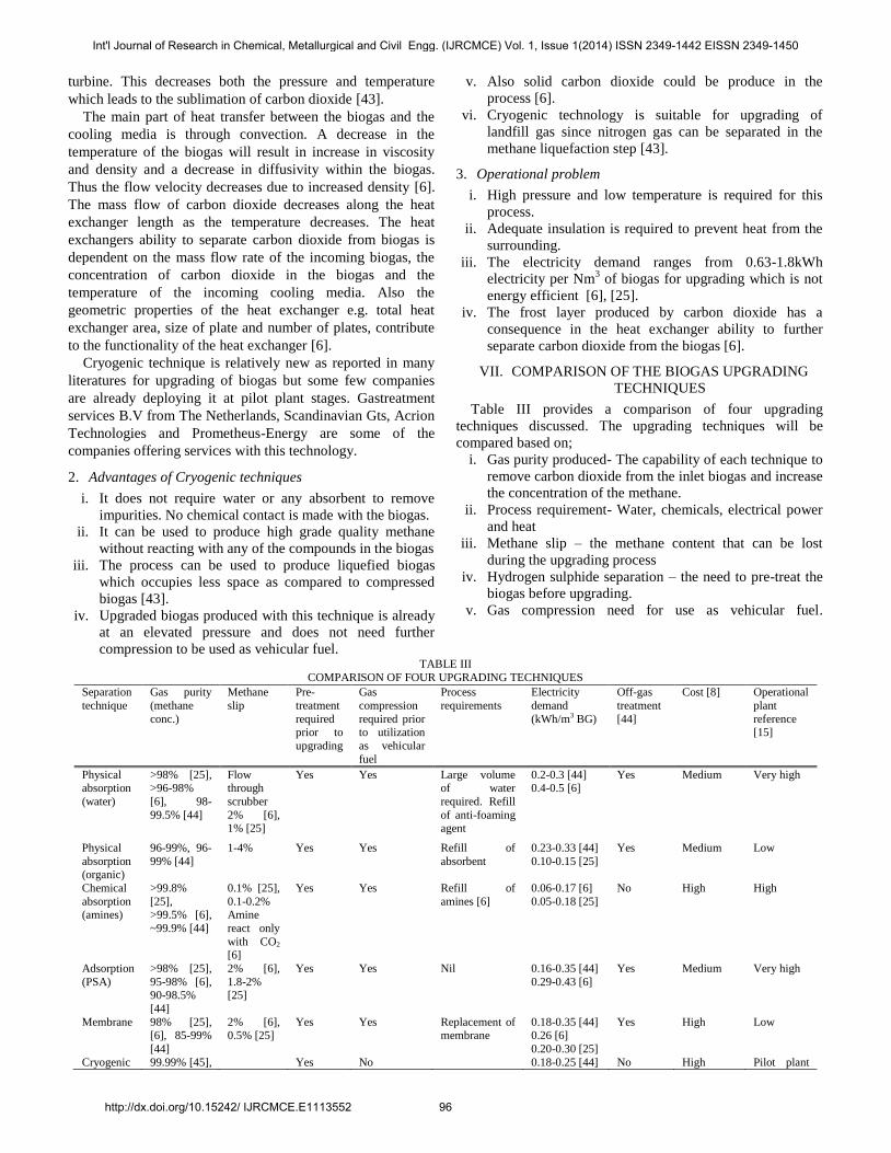
VII. COMPARISON OF THE BIOGAS UPGRADING
TECHNIQUES
Table III provides a comparison of four upgrading
techniques discussed. The upgrading techniques will be
compared based on;
i. Gas purity produced- The capability of each technique to
remove carbon dioxide from the inlet biogas and increase
the concentration of the methane.
ii. Process requirement- Water, chemicals, electrical power
and heat
iii. Methane slip – the methane content that can be lost
during the upgrading process
iv. Hydrogen sulphide separation – the need to pre-treat the
biogas before upgrading.
v. Gas compression need for use as vehicular fuel.
TABLE III
COMPARISON OF FOUR UPGRADING TECHNIQUES
Separation
technique
Gas purity
(methane
conc.)
Methane
slip
Pre-
treatment
required prior to
upgrading
Gas
compression
required prior to utilization
as vehicular
fuel
Process
requirements
Electricity
demand
(kWh/m3 BG)
Off-gas
treatment
[44]
Cost [8] Operational
plant
reference [15]
Physical absorption
(water)
>98% [25], >96-98%
[6], 98-
99.5% [44]
Flow through
scrubber
2% [6], 1% [25]
Yes Yes Large volume of water
required. Refill
of anti-foaming agent
0.2-0.3 [44] 0.4-0.5 [6]
Yes Medium Very high
Physical
absorption (organic)
96-99%, 96-
99% [44]
1-4% Yes Yes Refill of
absorbent
0.23-0.33 [44]
0.10-0.15 [25]
Yes Medium
Low
Chemical
absorption (amines)
>99.8%
[25], >99.5% [6],
~99.9% [44]
0.1% [25],
0.1-0.2% Amine
react only
with CO2 [6]
Yes Yes Refill of
amines [6]
0.06-0.17 [6]
0.05-0.18 [25]
No High High
Adsorption
(PSA)
>98% [25],
95-98% [6], 90-98.5%
[44]
2% [6],
1.8-2% [25]
Yes Yes Nil 0.16-0.35 [44]
0.29-0.43 [6]
Yes Medium Very high
Membrane 98% [25], [6], 85-99%
[44]
2% [6], 0.5% [25]
Yes Yes Replacement of membrane
0.18-0.35 [44] 0.26 [6]
0.20-0.30 [25]
Yes High Low
Cryogenic 99.99% [45], Yes No 0.18-0.25 [44] No High Pilot plant
Int'l Journal of Research in Chemical, Metallurgical and Civil Engg. (IJRCMCE) Vol. 1, Issue 1(2014) ISSN 2349-1442 EISSN 2349-1450
http://dx.doi.org/10.15242/ IJRCMCE.E1113552 96
separation >97% [6], 98-99.9%
[44]
0.42-0.63 [6] only
Of the four processes only chemical absorption requires a
substantial amount of heat for the regeneration of the amines
[6]. The electricity demand for cryogenic is very high at about
0.63kWh/m3 upgraded biogas while that of pressure swing
adsorption is about 0.5-0.6kWh/m3 upgraded biogas [6], [25].
All technologies require compression except cryogenic
separation for the upgraded biogas to be used as vehicular
fuel. The energy required to compress the gas depends on the
volume of the gas that is to be compressed, the inlet
temperature of the gas, the ratio of specific heat (Cp/Cv) for the
gas, inlet and outlet pressure and the efficiency of the
compressor. The ratio of specific heat is the only parameter
that depends on the composition of the biogas. Cp/Cv equals
1.307 and 1.304 for methane and carbon dioxide respectively
at 150C & 1 atm [25].
VIII. CONCLUSION
The biogas enrichment techniques reviewed in this paper
shows effectiveness in upgrading biogas to quality biomethane
for use as vehicular fuel. Absorption, Adsorption and
Membrane techniques with lots of technical expertise and
operational data can be deployed for upgrading biogas after a
careful evaluation of the investment cost. The investment cost
depends on the scale of the project but from literatures,
physical absorption and pressure swing adsorption has the
least investment cost over a large scale production level.
Cryogenic technique is still in its early stage of
implementation and would not be recommended for full scale
deployment. Upgraded biogas when used as fuel provides
much benefit to the ecosystem by reducing greenhouse gas
emission and ensuring a more sustainable environment.
REFERENCES
[1] C. M. Drapcho, N. P. Nhuan and T. H. Walker, Biofuels Engineering
Process Technology, McGraw Hill, 2008.
[2] V. K. Vijay, R. Chandra and P. M. V. Subbarao, "Vehicular Quality
Biomethane Production from Biogas by Using Automated Water
Scrubbing System," International Scholarly Research network, ISRN Renewable Energy, vol. 2012, p. 6, 2012.
[3] O. C. Boateng and E. M. Kwofie, "Water Scrubbing: A Better Option for
biogas Purification for Effective Storage," World Applied Sciences
Journal 5(Special Issue for Environment), pp. 122-125, 2009.
[4] T. Al Seadi, D. Rutz, H. Prassl, M. Kottner, T. Finsterwalder, S. Volk
and R. Janssen, Biogas Handbook, T. Al Seadi, Ed., Denmark, Esbjerg: University of Southern Denmark, 2008.
[5] P. O. G. Z.-T. A. C. M. Harasimowicz, "Application of polyimide
membranes for biogas purification and enrichment," Journal of hazardous Material, vol. 144, no. 3, pp. 698-702, 18 june 2007.
[6] S. Jonsson and J. Westman, "Cryogenic Biogas Upgrading Using Plate
Heat Exchangers," Chalmers University of Technology, Goteborg, Sweden, 2011.
[7] J. C. Reijenga, L. Bini, J. I. Maassen, P. A. Van Meel, J. De Hullu, S.
Shazad and J. M. Vaessen, "Comparing Different Biogas Upgrading Techniques: Interim Report," Eindhoven University of Technology,
2008.
[8] E. Dirkse, "Biogas Upgrading Using the DMT TS-PWS Technology," DMT Environmental Technology, 2008.
[9] G. M. K. Babu and K. A. Subramanian, Alternative Transportation Fuels:
Utilisation in Combustion Engines, Boca Raton: CRC Press, Taylor &
Francis Group, 2013.
[10] M. Persson, "Evaluation of Upgrading Technique for Biogas," swedish
Gas Center, Lund, 2003.
[11] R. C. P. M. V. S. a. S. S. K. Virendra K. Vijay, "Biogas Purification and
Bottling into CNG Cylinders: Producing Bio-CNG from Biomass for
Rural Automotive Applications," in The 2nd Joint International Conference on 'Sustainable Energy and Environment (SEE 2006)',
Bangkok, Thailand, 2006.
[12] Sustainable Transport Group, "Biogas as Road Transport Fuel: An Assessment of the Potential Role of Biogas as a Renewable Transport
Fuel," NSCA, England, 2006.
[13] D. Deublein and A. Steinhauser, Biogas from waste & Renewable
Resources: An Introduction, Weinheim: Wiley-VCH, 2008.
[14] P. Cekanova, N. Jasminska, T. Brestovic and E. Schvarzbacherova, "Biogas Upgrading Processess for the production of Natural gas
substitute," The Holistic Approach to Environment, pp. 53-62, 24 05
2011.
[15] A. Petersson and A. Wellinger, "Biogas Upgrading Technologies-
Developments & Innovation," IEA Bioenergy, 2009.
[16] B. Shimekit and H. Mukhtar, "Natural Gas Purification Technologies - Major Advances for CO2 Separation and Future Directions," in Advances
in Natural Gas Technology, H. Dr. Al-Megren, Ed., InTech, 2012, pp.
237-270.
[17] M. Persson, O. Jonsson and A. Wellinger, "Biogas upgrading to Vehicle
Fuel Standard and Grid Injection," IEA Bioenergy, Vienna, 2006.
[18] C. Andrzej and Z. Roman, Absorption: Fundamentals & Application, 1st ed., Pergamon Press, 1993.
[19] K. L. Arthur and N. B. Richard, Gas Purification, 5th ed., New York:
Gulf Publishing Compny, 1997.
[20] F. R. James, Absorption adn Stripping; The Enginnering Hndbook,
Austin: CRC PRESS LLC, 2005, p. Chapter 59.
[21] Vienna University of Technology, "Biogas to Biomethane Technology Review," Vienna, Austria, 2012.
[22] H. Nie, H. Jiang, D. Chong, Q. Wu, C. Xu and H. Zhou, "Comaprison of
Water Scrubbing and Propylene Carbonate Absorption for Biogas Upgrading Process," Energy & Fuels, no. 27, p. 3239−3245, 13 May
2013.
[23] M. Gotz, F. Ortloff, R. Reimert, O. Basha, B. I. Morsi and T. Kolb, "Evaluation of Organic and Ionic Liquids for Three-phase Methanation
and Biogas Purification Processes," Energy & Fuels, vol. 27, pp. 4705-
4716, 27 June 2013.
[24] W. Stumm and J. J. Morgan, Aquatic Chemistry: Chemical Equilibria
and Rates in Natural Waters, 3rd ed., New York: Wiley, 1996.
[25] F. Bauer, C. Hulteberg, T. Persson and D. Tamm, "Biogas upgrading - Review of commercial technologies," Svenskt Gastekniskt Center (SGC)
AB, Malmö, Sweden, 2013.
[26] Y. Belmabkhout, N. Heyman, G. De Weireld and A. Sayari, "Simultaneous Adsorption of H2S and CO2 on Triamine Grafted Pore-
Expanded Mesoporous MCM-41 Silica," Energy & Fuels, pp. 1310-
1315, 04 02 2011.
[27] Q. Zhau, E. Leonhardt, C. MacConnell, C. Frear and S. Chen,
"Purification Technologies for Biogas Generated by Anaerobic
Digestion," CSANR Research Report, pp. 01-24, 2010.
[28] N. Tippayawong and P. Thanompongchart, "Biogas quality upgrade by
simultaneous removal of CO2 and H2S in a Packed Column Reactor,"
Energy, pp. 1-4, 2010.
[29] V. D. Prakash and M. V. Vijaykumar, "Quickly Design CO2-Amine
Absorber," Indian Journal of Chemical Technology, vol. 13, pp. 47-52,
Januanry 2006.
[30] N. Kasiri and M. A. Ghayyem, "Rate Based Model in H2S and CO2
Absorption Column Using Alkanolamine Solutions," IUST International Journal of Engineering Science, vol. 19, no. 5-2, pp. 89-98, 2008.
[31] K. H. Mohamadbigy, M. Bazm, R. Behradi and R. Binesh, "Amine
Absorption Column Design Using Mass Transfer Rate Simulation,"
Int'l Journal of Research in Chemical, Metallurgical and Civil Engg. (IJRCMCE) Vol. 1, Issue 1(2014) ISSN 2349-1442 EISSN 2349-1450
http://dx.doi.org/10.15242/ IJRCMCE.E1113552 97
Petroleum & Coal, vol. 47, no. 2, pp. 39-46, November 2005.
[32] J. I. Huertas, N. Giraldo and S. Izquierdo, Removal of H2S and CO2
from Biogas by Amine Absorption, Mass Transfer in Chemical
Engineering Process, Vols. Automotive Engineering Research Center-
CIMA of Tecnologico de Monterrey,, D. J. Markoš, Ed., Mexico: InTech, 2011, pp. 133-150.
[33] C. A. Grande, "Advances in Pressure Swing Adsorption for Gas
Separation," International Scholarly Research Network Chemical Engineering, vol. Volume 2012, no. Article ID 982934, p. 13, 2012.
[34] Vienna University of Technology, "Biogas to Biomethane Technology
Review," Research Division Thermal Process Engineering and Simulation, Austria, 2012.
[35] C. A. Grande, "Biogas upgrading by Pressure Swing Adsorption," in Biofuel's Engineering Process Technology, D. M. A. D. S. Bernardes,
Ed., Rijeka, InTech, 2011, pp. 66-84.
[36] T. Patterson, S. Esteves, R. Dinsdale and A. Guwy, "An Evaluation of the Policy and Techno-Economic Factors Affecting the Potential for
Biogas Upgrading for Transport use in UK," Energy Policy, no. 39, pp.
1806-1816, 11 January 2011.
[37] C. A. Grande and A. E. Rodrigues, "Biogas to Fuel by Vacuum Pressure
Swing Adsorption: Behaviour of Equilibrium and Kinetic Adsorption,"
Ind. Eng. Chem. Res, vol. 46, pp. 4595-4605, 2006.
[38] T. Cnop, D. Dortmundt and M. Schott, "Continued Development of Gas
Separation membrane for Highly Sour Service," UOP LLC, Illinios,
USA, 2007.
[39] E. Tocci and P. Pullumbi, "Mulit-Scale Molecular Modelling
Approaches for Designing/Selecting Polymers Used for Developing
Novel Membrane," in Membrane Engineering for the Treatment of Gases: Gas Separation Problems with Membrane, vol. Vol. 1, E. Drioli
and G. Barbieri, Eds., Royal Society of Chemistry, 2011, pp. 1-28.
[40] J. I. Marriott, "Detail Modelling & Optimal Design of Membrane Separation System," University College London, London, 2001.
[41] R. W. Baker, Membrane Technology and Application, 2nd ed.,
Chichester: Wiley, 2004, pp. 1-15.
[42] M. Miltner, A. Makaruk, H. Bala and M. Harasek, "Biogas Upgrading
for Transportation Purposes; Operational Experience with Austria First
Bio-CNG Plant," Vienna University of Technology, Vienna, 2009.
[43] N. Johansson, "Production of liquid biogas, LBG, with Cryogenic and
Conventional Upgrading Technology-Description of Systems and
Evaluation of Energy Balances," Lunds Universitet, Lunds, 2008.
[44] A. Wellinger, J. Murphy and D. Baxter, The Biogas Handbook: Science,
Production & Application, S. Hughes, Ed., Philadelphia: Woodhead
Publishing, 2013.
[45] M. J. Tuinier and M. V. S. Annaland, "Biogas Purification Using
Cryogenic Packed Bed Technology," Industrial & Engineering
Chemistry Research (I&EC), pp. 5552-5558, 15 March 2012.
Int'l Journal of Research in Chemical, Metallurgical and Civil Engg. (IJRCMCE) Vol. 1, Issue 1(2014) ISSN 2349-1442 EISSN 2349-1450
http://dx.doi.org/10.15242/ IJRCMCE.E1113552 98


