
61 ا را– ا رإ دا ن در– ) ددر 1ا (1436 - رم2014د
Enhancing AErodynamics performancs of NACA 23012 Ahmed Alrayah & Obai Younis
Ahmed Alrayah ( )
Obai Younis ( )
��������� �
������������������������������������� �23012 NACA���
� ������� ������ ���� ������ �� ������������������� ���� ������ �����
��������������������������������������������������������������������
� ������� ��� ������ ������� ������ ��� ������� ����� ����������� ������
������������������������������������������������������������������
������ �������� ��������������� ����������������� ���� ������ �����
������������������������ ������� ��������� ��������������������� �������
����������� ��� ����������������������������� �������������� ����������
�������������������� ��������� ��������29.42� ���������������������� ����
��������������� ���� ���� ���� ���������������� ������� �������
�������������������������������������������������������������������
�CFD����������������������������������� ��� ���������������������
����������������������������������������������������������������������� �
)(Faculty of Engineering , I UA , Sudan, Khartoum )(Faculty of Engineering, U of K, Sudan, Khartoum
Enhancing Aerodynamics
performancs of NACA 23012 by
Using Backward Step

62 ا را– ا رإ دا ن در– ) ددر 1ا (1436 - رم2014د
Enhancing AErodynamics performancs of NACA 23012 Ahmed Alrayah & Obai Younis
Abstract The main objective of this paper is to improve
the aerodynamics characteristics of National
Advisory Committee for Aeronautics (NACA
23012) by introducing backward facing steps.
Investigation of the influence of the step location
on pressure distributions and therefore, on lift
and drag, for a wider range of angle of attack
were considered in order to understand the
physical phenomena of flow around air foil, as
well as flow visualization. Upper, lower and
hybrid steps configurations were examined to
show their effect on lift and on lift-to-drag ratios.
The results suggest that incorporation of
backward-facing steps on the lower surface that
is located at the mid-chord and extend back to
the trailing edge with 50% depth on lower side of
the air foil thickness may lead to considerable
enhancements in lift coefficients. Drag generated
with introducing steps is very high especially
when hybrid steps are located.

63 ا را– ا رإ دا ن در– ) ددر 1ا (1436 - رم2014د
Enhancing AErodynamics performancs of NACA 23012 Ahmed Alrayah & Obai Younis
1. Introduction The maximum lift of an air foil is associated
with the separation of the boundary layer on its
suction side. Thus the numerical prediction of
the maximum lift must deal with the pressure
distribution of an air foil section with partly
separated flow and with the interaction between
this pressure distribution and the boundary
layer [1]. Numerous experiments have revealed
the sequence of flow events depicted in "fig.1"
first; a vortex starts to develop near the air foil
trailing edge as the angle of attack is rapidly
increased past the stall angle. This vortex then is
converted downstream near the air foil surface
which causes an increase in lift due to the
suction (upper surface) induced by the vortex.
The magnitude of the lift increasing depends on
the strength of the vortex and its distance from
the surface. The stream wise movement of the
vortex depends on the air foil shape and the
pitch rate. As the vortex is connected past the
trailing edge, the lift briefly attains its maximum
value and then start to drop rapidly [2].

64 ا را– ا رإ دا ن در– ) ددر 1ا (1436 - رم2014د
Enhancing AErodynamics performancs of NACA 23012 Ahmed Alrayah & Obai Younis
Fig.1. Sequence of flow separation.
Richard L.Kline and Floyd F.Fogleman
introduced a breakthrough concept in air foil
design with their stepped air foils developed
early. The Ultimate Paper Airplane [3] by Richard
L.Kline & F.Fogleman describes that the object of
this design was to develop an improved air foil
with enhanced lift, drag and stability
characteristics and adaptability over a wide
range of speeds. Shifting to the review of studies
conducted on stepped air foils, it was in 1994
that the benefits of KF air foils were scientifically
proven through experiments and flight testing by
Demeter G.Fertis [4]. Aerodynamic studies on
stepped air foils were conducted by Stephen
Witherspoon [5] and Fathi Finaish, for different
configurations defined by the step lengths,
depths, and the location of steps on air foil

65 ا را– ا رإ دا ن در– ) ددر 1ا (1436 - رم2014د
Enhancing AErodynamics performancs of NACA 23012 Ahmed Alrayah & Obai Younis
chord. Experimental tests and numerical
investigation with steps on NACA 0012 and
23012 air foils showed that higher lift coefficients
were obtained with lower surface step located at
half-chord, extending till the trailing edge at all
angles of attack ranging from 0 to 10 deg.
Further, upper surface steps located at half-
chord and extending till 62.5% chord generated
higher L/D ratios when compared with
unmodified NACA 0012 air foil at incidence(s)
around 10deg.
Geometric optimization of lifting surfaces
during flight has the potential to enhance aircraft
performance for a wide range of flight
manoeuvres. Shorter take-off and landing
distances, slower take-off and landing speeds,
lower fuel consumption, and longer range are
just few examples of performance characteristics
that can be enhanced by optimizing the geometry
of lifting surfaces during flight. Wide range of
methods have been employed using devices such
as flaps, slats, spoilers, and drooped leading
edges. These systems are designed to maximize
aerodynamic performance for limited flight
manoeuvres/conditions relying on traditional

66 ا را– ا رإ دا ن در– ) ددر 1ا (1436 - رم2014د
Enhancing AErodynamics performancs of NACA 23012 Ahmed Alrayah & Obai Younis
aerodynamic concepts that utilize attached flows
[6]. The air foil should be able to function at high
angles of attack without stalling. If we couple
these desired parameters, a multitude of air foil
designs can be developed, each having its own
aerodynamic characteristics tailored to a specific
flight condition [7]. Flow over submerged bodies
such as an aircraft and or a submarine can be
worked upon to delay boundary layer transition,
postpone separation, increase lift, reduce skin-
friction and pressure drag, augment turbulence,
enhance heat transfer, or suppress noise. Future
applications in the field of aeronautics include
providing structurally efficient alternatives to
flaps or slats; cruise application on conventional
take-off and landing aircraft including boundary
layer control on thick span-loader wings; as well
as increased leading edge thrust, and enhanced
fuselage and upper surface lift with most of the
new developments to be made pertain to the
employment of various flow control techniques [8].
The geometry of a conventional NACA 23012
airfoil was modified by introducing backward
facing steps, which forms a relatively new family
of air foil designs, popularly known as “KF (Kline-

67 ا را– ا رإ دا ن در– ) ددر 1ا (1436 - رم2014د
Enhancing AErodynamics performancs of NACA 23012 Ahmed Alrayah & Obai Younis
Fogleman) airfoils”. Stepped air foils use the
concept of trapped vortex and consequently there
is the trapped vortex flow control. Flow rotation
induced near the step face generates a primary
vortex as shown in "fig.2", a secondary vortex
forms in the opposite direction after the flow
reattaches itself to the boundary. Thus an air foil
with a step traps vortices in the cavity which
primarily are the noticeable as well as
distinguishing flow features as compared with
the flow over conventional air foils. The formation
of these vortices alter the flow field
characteristics thereby altering the lift, drag
characteristics depending on whether the step is
introduced on the upper or lower edge or both
upper and lower edge of air foil [9].
Fig.2. Typical flow field around an air foil with steps on upper and
lower edges.
68 ا را– ا رإ دا ن در– ) ددر 1ا (1436 - رم2014د
Enhancing AErodynamics performancs of NACA 23012 Ahmed Alrayah & Obai Younis
Investigations of the influence of the step
location on pressure distributions and therefore,
on lift and drag, for a wider range of angle of
attack were considered in order to understand
the physical phenomena of flow around air foil,
as well as flow visualization. CFD simulations
package (Ansys, Fluent) is suitable to use for
computational requirement.
It’s suggested that the resulting flow field
around a stepped airfoil must improve lift and/or
reduced drag and produce better stall
characteristics, depending on the airfoil
configuration and where the step is located. We
aimed to identify the optimum setting of steps
and the pest position on airfoil and making the
effective use of vortices resulting from stepped
configurations at various flight conditions.
2. RESULTS AND DISCUSSIONS: Four cases has been tested numerically for
modified and conventional NACA 23012, the
steps were located at upper surface, lower
surface and “upper and lower surface at the
same time”. Conventional and modified airfoils
were then tested numerically at various angles of
attack (5°, 10°, 15°, 20°, 25°, and 30°).Reynolds

69 ا را– ا رإ دا ن در– ) ددر 1ا (1436 - رم2014د
Enhancing AErodynamics performancs of NACA 23012 Ahmed Alrayah & Obai Younis
number of (Re = 61082.1 ), based on the chord of the
airfoil (1m) and free stream velocity of (27.4m/s),
is considered. A finite volume method based CFD
tool which solves the governing equations of
conservation of mass and momentum was the
flow solver used for the entire numerical
analysis.
Fig.3. Computational Domain
Inlet
Velocity =27.4 m/s
Pressure gauge =0
Airfoil=wall
Outlet Pressure gauge =0

70 ا را– ا رإ دا ن در– ) ددر 1ا (1436 - رم2014د
Enhancing AErodynamics performancs of NACA 23012 Ahmed Alrayah & Obai Younis
The computational domain comprises of four
blocks for base airfoil configurations, while the
single upper step configurations had five mesh
blocks also the single lower step configurations
had a same mesh blocks, while the upper &
lower step configurations had seven mesh blocks
as shown in "figs.4, 5 and 6" respectively. The
flow has been modeled as steady, incompressible
in the flow domain comprising several blocks.
The fluid chosen is air at standard atmospheric
conditions which were set as the reference values
along with the free-stream velocity set
corresponding to the flow “Re” for each
simulation run for the preliminary cases of
study. The inlet has been set as “Velocity Inlet”
which includes all the front, top and bottom
edges of the flow domain.

71 ا را– ا رإ دا ن در– ) ددر 1ا (1436 - رم2014د
Enhancing AErodynamics performancs of NACA 23012 Ahmed Alrayah & Obai Younis
� �Fig.4. Block structure and Grid distribution of the flow domain over
a base air foil.
Fig.5. Blocks and Grid distribution of domain over air foil with upper
surface step.
72 ا را– ا رإ دا ن در– ) ددر 1ا (1436 - رم2014د
Enhancing AErodynamics performancs of NACA 23012 Ahmed Alrayah & Obai Younis
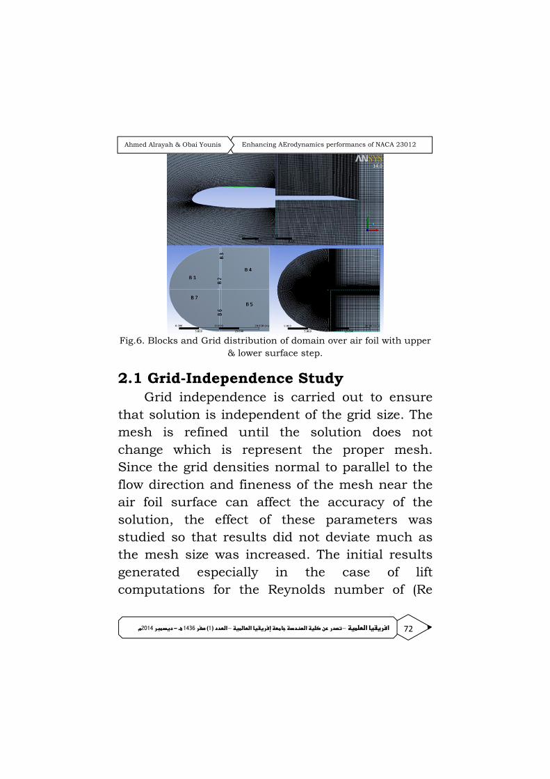
Fig.6. Blocks and Grid distribution of domain over air foil with upper
& lower surface step.
2.1 Grid-Independence Study Grid independence is carried out to ensure
that solution is independent of the grid size. The
mesh is refined until the solution does not
change which is represent the proper mesh.
Since the grid densities normal to parallel to the
flow direction and fineness of the mesh near the
air foil surface can affect the accuracy of the
solution, the effect of these parameters was
studied so that results did not deviate much as
the mesh size was increased. The initial results
generated especially in the case of lift
computations for the Reynolds number of (Re

73 ا را– ا رإ دا ن در– ) ددر 1ا (1436 - رم2014د
Enhancing AErodynamics performancs of NACA 23012 Ahmed Alrayah & Obai Younis
=6
1082.1 ), were in descent agreement with the
experimental data [4].
Fig.7. compares experimental data [4] with the preliminary numerical
results for the cases studied.
Mesh resolution can be checked by plotting
the distribution of Y+ near the air foil wall, the
values of Y+ are dependent on the resolution of
the mesh and the Reynolds number of the flow,
and are defined only in wall-adjacent cells.
In this case, the Y+ values are slightly high
and maximum is 325 as shown in "fig.8". The lift
coefficient can be better predicted if the Y+ value
is kept in the range of 50-250 [22]. In order to
meet this condition, refine the cells adjacent to
wall using adaption as shown by "fig.9"

74 ا را– ا رإ دا ن در– ) ددر 1ا (1436 - رم2014د
Enhancing AErodynamics performancs of NACA 23012 Ahmed Alrayah & Obai Younis
Fig.8. Wall Y+ Plot
Fig.9. Wall Y+ Plot after adaptation
Fig.10. Adapted mesh near the wall of airfoil.
75 ا را– ا رإ دا ن در– ) ددر 1ا (1436 - رم2014د
Enhancing AErodynamics performancs of NACA 23012 Ahmed Alrayah & Obai Younis
2.2 Aerodynamics Characteristics:
2.2.1 Pressure distributions
Comparison has been taken for specific angle
of attack (15°) for base, upper surface step, lower
surface step and upper & lower surface step
,(hybrid step) air foils at the same time.
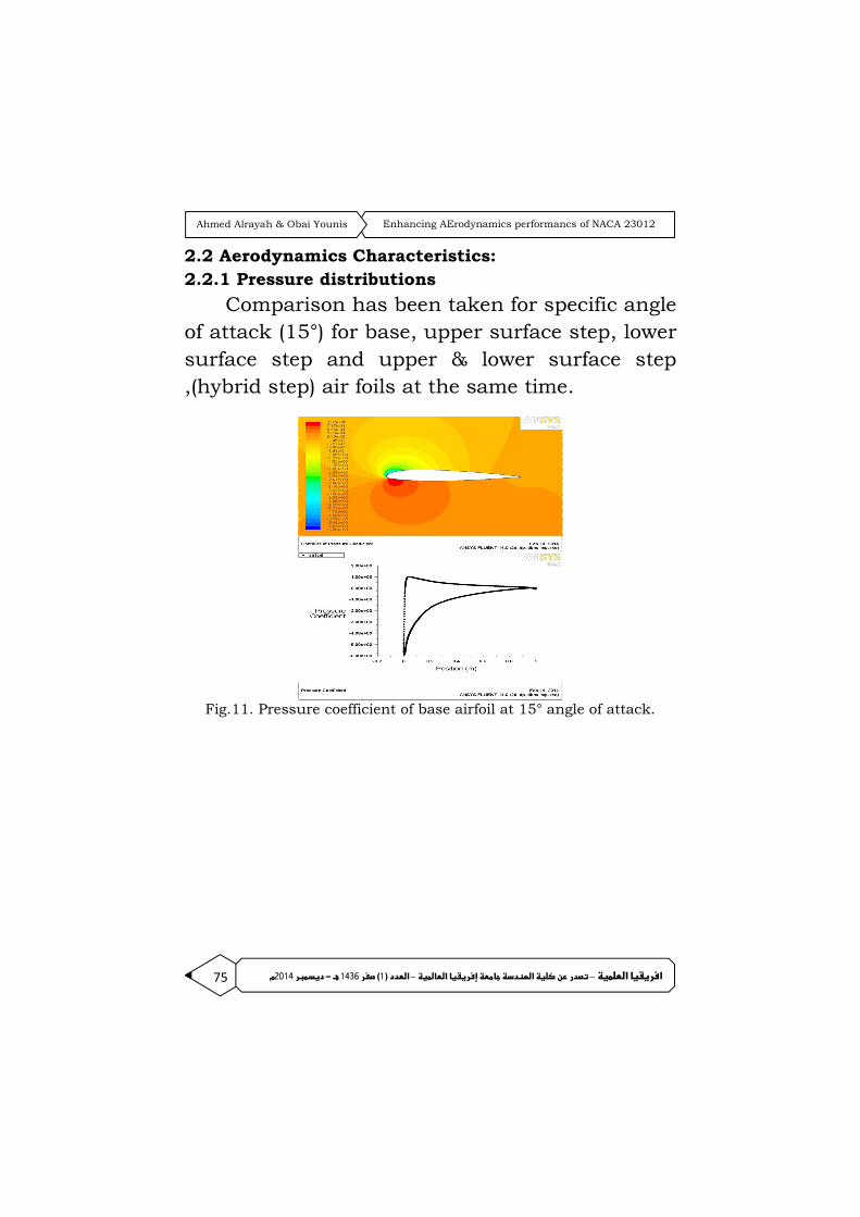
Fig.11. Pressure coefficient of base airfoil at 15° angle of attack.

76 ا را– ا رإ دا ن در– ) ددر 1ا (1436 - رم2014د
Enhancing AErodynamics performancs of NACA 23012 Ahmed Alrayah & Obai Younis
Fig.12. Pressure coefficient of upper step airfoil at 15° angle of attack
Fig.13. Pressure coefficient of hybrid step air foil at 15° angle of attack.

77 ا را– ا رإ دا ن در– ) ددر 1ا (1436 - رم2014د
Enhancing AErodynamics performancs of NACA 23012 Ahmed Alrayah & Obai Younis
From "figs. 11 and 12 " there is clear
deviation appears when the base airfoils is
compared with upper surface step airfoil, the
coefficient pressure start at leading edge point 0
and rapidly decrease toward the trailing edge.
The Cp had a maximum of 1.02 while minimum
value recorded as -5.90 as shown by "fig.10" this
is agreement with value observed in Cp in the
same figure. The upper surface step airfoil had a
maximum Cp not exceed 1.35 and a minimum
value of Cp is -2.56.
The step reduce the area which undergoes
air pressure, this indicate that the associated lift
of lower surface step air foil is higher than any
other type of air foils i.e. (base or stepped) for the
same angle of attack 15°. It can be concluded
that the minimum value observed have smaller
value over all values of pressure in other
configuration above which mean low pressure in
upper surface of air foil and better associated lift
due to “suction” on upper surface.
78 ا را– ا رإ دا ن در– ) ددر 1ا (1436 - رم2014د
Enhancing AErodynamics performancs of NACA 23012 Ahmed Alrayah & Obai Younis
2.2.2 VELOCITY CONTOURS
In “figs.12 and 13" the velocity contours are
shown for all cases base and modified air foil, a
slight difference between base and upper surface
step air foil appear as shown by "fig.12" Velocity
contour had a range of values which vary around
air foil from 0 to 6.61 m/s for base air foil and
4.12 m/s for the upper step air foil. Contour
shape around base air foil indicates that there is
no vortex formed on upper side of air foil and
hence a slight separation point. The maximum
value of lift is observed at this angle of attack 15°
for both base and lower surface step air foil. The
upper surface step air foil it’s shown clearly there
are more vortices on upper side of air foil and
hence separation point position exceeds the mid
chord. In the side of step there is low in speed at
upper surface body as indicated by blue colour.
This redaction of flow causes formation of
vortices, increasing in drag and an increase in
probability of delaying the stall. Hybrid step on
figure (15) fixed the problem faced by upper step
this is appear clearly when comparison between
figures (14) and (15) take place.

79 ا را– ا رإ دا ن در– ) ددر 1ا (1436 - رم2014د
Enhancing AErodynamics performancs of NACA 23012 Ahmed Alrayah & Obai Younis
Fig.14. Velocity contours of base and upper surface step airfoil for 15° angle
of attack.
Fig.15 Velocity contours of lower surface step and hybrid step airfoil for 15°
angle of attack.

80 ا را– ا رإ دا ن در– ) ددر 1ا (1436 - رم2014د
Enhancing AErodynamics performancs of NACA 23012 Ahmed Alrayah & Obai Younis
Fig.16. CL for base and modified air foils vs. angle of attack “α”
Fig (16) represents lift coefficient “Cl” versus
angle of attack “α”, the highest value of “Cl”
achieved by lower surface step air foil while the
base had a second highest value of “Cl” achieved
at 15° angle of attack. Lower surface step air foil
show good stability in stall more than other
types, upper step have no effect on aerodynamics
characteristics of air foil. However the maximum
lift coefficient increases from about 1.3 for the
base air foil to 1.4186 for the hybrid step air foil.
While the maximum drag coefficient increases
from about 0.058 for the air foil with no step to
about 0.0954 for the hybrid step air foil for the
same angle of attack 15°.
81 ا را– ا رإ دا ن در– ) ددر 1ا (1436 - رم2014د
Enhancing AErodynamics performancs of NACA 23012 Ahmed Alrayah & Obai Younis
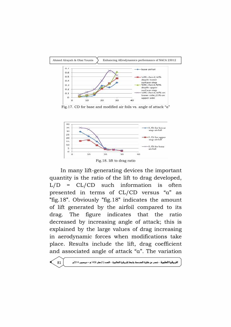
Fig.17. CD for base and modified air foils vs. angle of attack “α”
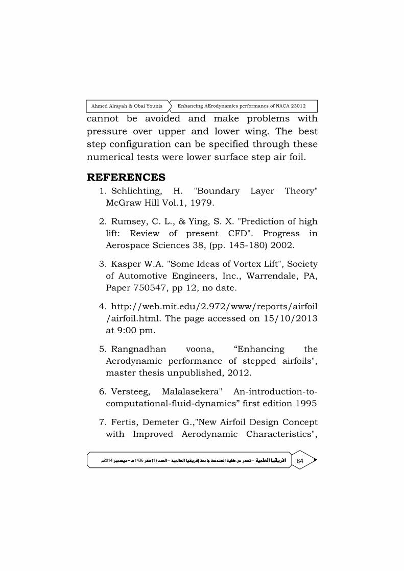
Fig.18. lift to drag ratio
In many lift-generating devices the important
quantity is the ratio of the lift to drag developed,
L/D = CL/CD such information is often
presented in terms of CL/CD versus “α” as
"fig.18". Obviously "fig.18" indicates the amount
of lift generated by the airfoil compared to its
drag. The figure indicates that the ratio
decreased by increasing angle of attack; this is
explained by the large values of drag increasing
in aerodynamic forces when modifications take
place. Results include the lift, drag coefficient
and associated angle of attack “α”. The variation

82 ا را– ا رإ دا ن در– ) ددر 1ا (1436 - رم2014د
Enhancing AErodynamics performancs of NACA 23012 Ahmed Alrayah & Obai Younis
of “α” gives more good prediction of the
aerodynamics characteristics of the airfoil also
gives more visualization of the flow filed. Stall
angle has been detected at 15° angle of attack
when base airfoil is tested for Reynolds number
of (Re =6
1082.1 ) and associated (Cl=1.3). It’s
necessary to compare base airfoil results with
modified airfoil to ensure that the hypotheses
introduced early are correct. However stall has
been observed for all cases tested; when the
lower surface step is compared with base airfoil
it’s found that there is increasing in lift and drag
coefficient for the same angle of attack 15°. The
lower surface step does not delay the stall
characteristic while the upper surface step has
stability of stall has been observed at α=20°, “Cl
=1.025” and “Cd=0.252”. it’s necessary to realize
that there are highly decreasing in “Cl”
magnitude if its compared with other type of
airfoil this is indicate that the upper surface step
have no significant effect on airfoil performance
characteristics because there is decreasing in
“Cl” magnitude and increasing in “Cd” more than
other types mentioned above.

83 ا را– ا رإ دا ن در– ) ددر 1ا (1436 - رم2014د
Enhancing AErodynamics performancs of NACA 23012 Ahmed Alrayah & Obai Younis
1. CONCLUSION NACA 23012 air foil had been compared with
modified (backward stepped) types in order to
enhance the aerodynamic characteristics of
conventional NACA 23012 air foil and to examine
the advantages and disadvantages of the new
design concept. The results presented constitute
the next step towards understanding the effects
of a step-induced vortex on the aerodynamic
characteristics of a conventional NACA 23012 air
foil for a range of angles of attack. The research
has been performed on a relatively new family of
air foils, which in itself needs further studies.
The objective of study was to enhance the
aerodynamic performance of the base NACA
23012 air foil for a chosen range of step
configurations and angles of attack. Hence the
major outcome is the increscent in lift over
conventional NACA 23012 air foil except when
upper surface is located, while Drag-coefficient
data indicate that with the introduction of a step;
drag increased. This is consistent in all the
modified air foil cases studied. High drag
generation is in need of more studies in order to
reduce it. Hybrid step generate much drag
84 ا را– ا رإ دا ن در– ) ددر 1ا (1436 - رم2014د
Enhancing AErodynamics performancs of NACA 23012 Ahmed Alrayah & Obai Younis
cannot be avoided and make problems with
pressure over upper and lower wing. The best
step configuration can be specified through these
numerical tests were lower surface step air foil.
REFERENCES 1. Schlichting, H. "Boundary Layer Theory"
McGraw Hill Vol.1, 1979.
2. Rumsey, C. L., & Ying, S. X. "Prediction of high
lift: Review of present CFD". Progress in
Aerospace Sciences 38, (pp. 145-180) 2002.
3. Kasper W.A. "Some Ideas of Vortex Lift", Society
of Automotive Engineers, Inc., Warrendale, PA,
Paper 750547, pp 12, no date.
4. http://web.mit.edu/2.972/www/reports/airfoil
/airfoil.html. The page accessed on 15/10/2013
at 9:00 pm.
5. Rangnadhan voona, “Enhancing the
Aerodynamic performance of stepped airfoils",
master thesis unpublished, 2012.
6. Versteeg, Malalasekera" An-introduction-to-
computational-fluid-dynamics” first edition 1995
7. Fertis, Demeter G.,"New Airfoil Design Concept
with Improved Aerodynamic Characteristics",

85 ا را– ا رإ دا ن در– ) ددر 1ا (1436 - رم2014د
Enhancing AErodynamics performancs of NACA 23012 Ahmed Alrayah & Obai Younis
Journal of Aerospace Engineering, Vol. 7, NO. 3,
pp. 328-339, July, 1994.
8. Versteeg, Malalasekera" An-introduction-to-
computational-fluid-dynamics” first edition 1995
9. Ringleb F.O., "Separation control by trapped
vortices", In: Boundary Layer and Flow
Control", Ed. Lachmann G.V., Pergamon Press,
Oxford, pp. 265–294, 1961.
10. Davidson, L. "Fluid mechanics, turbulent
flow and turbulence". Chalmers University of
Technology” 2011
11. Kruppa E.W "A Wind Tunnel Investigation
of the Kasper Vortex Concept" AIAA, Paper 77-
310, pp. 10, 1977


