— Lands & ROW
Canada
Enbridge Pipeline Crossing Guidelines, Canada — Application Guidance Details May 2020 v2.0
Page 2
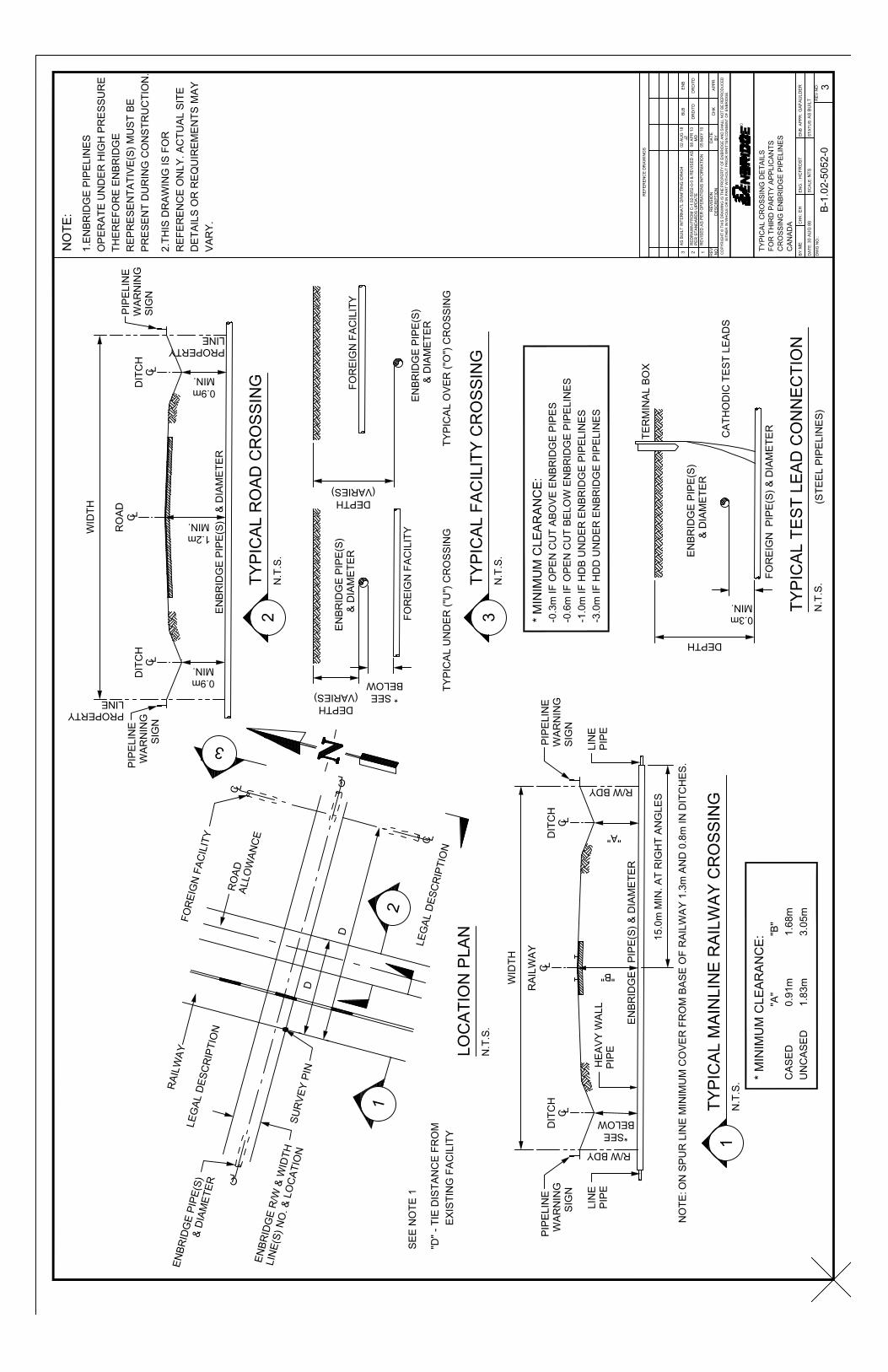
Application Guidance Details 1. WHO REQUIRES CONSENT? Consent is governed by the Canada Energy Regulator (CER) for interprovincial or international (federally regulated) pipelines and the Alberta Energy Regulatory (AER) for intra-provincial (provincially regulated) pipelines within the Province of Alberta. To ensure our pipelines and facilities operate safely written consent from Enbridge must be obtained in Canada before any of the following occur:
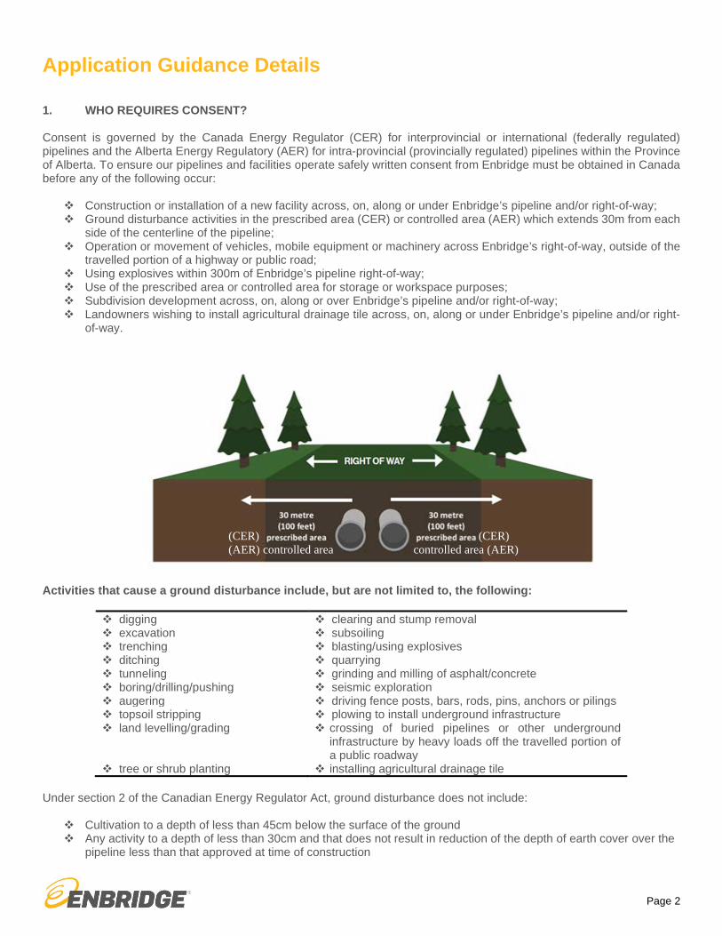
Construction or installation of a new facility across, on, along or under Enbridge’s pipeline and/or right-of-way; Ground disturbance activities in the prescribed area (CER) or controlled area (AER) which extends 30m from each
side of the centerline of the pipeline; Operation or movement of vehicles, mobile equipment or machinery across Enbridge’s right-of-way, outside of the
travelled portion of a highway or public road; Using explosives within 300m of Enbridge’s pipeline right-of-way; Use of the prescribed area or controlled area for storage or workspace purposes; Subdivision development across, on, along or over Enbridge’s pipeline and/or right-of-way; Landowners wishing to install agricultural drainage tile across, on, along or under Enbridge’s pipeline and/or right-
of-way.
Activities that cause a ground disturbance include, but are not limited to, the following: digging clearing and stump removal excavation subsoiling trenching blasting/using explosives ditching quarrying tunneling grinding and milling of asphalt/concrete boring/drilling/pushing seismic exploration augering driving fence posts, bars, rods, pins, anchors or pilings topsoil stripping plowing to install underground infrastructure land levelling/grading crossing of buried pipelines or other underground
infrastructure by heavy loads off the travelled portion of a public roadway
tree or shrub planting installing agricultural drainage tile Under section 2 of the Canadian Energy Regulator Act, ground disturbance does not include:
Cultivation to a depth of less than 45cm below the surface of the ground Any activity to a depth of less than 30cm and that does not result in reduction of the depth of earth cover over the
pipeline less than that approved at time of construction
(CER) controlled area (AER)
(CER) (AER) controlled area

Page 3
2. CROSSING A PIPELINE WITH AN AGRICULTURAL VEHICLE OR MOBILE EQUIPMENT For pipelines regulated by the Canada Energy Regulator, the Canadian Energy Regulator Pipeline Damage Prevention Regulations – Authorizations provides that persons operating agricultural vehicles or mobile equipment across pipelines may do so in low-risk areas, under certain conditions:
the loaded axle weight and tire pressures of the vehicle or mobile equipment are within the manufacturer’s approved limits and operating guidelines; AND
the point of crossing has not been the subject of a notification from the pipeline company that crossing at that location could impair the pipeline’s safety or security.
This applies to vehicles or mobile equipment used for agricultural activities in the production of crops and the raising of animals and includes pasturing and cultivation activities such as tillage, plowing, disking and harrowing. For pipelines regulated by the Alberta Energy Regulator, the Pipeline Regulation (under the Pipeline Act) provides that persons operating vehicles or equipment used for farming operations; or use of off-highway vehicles [as defined in section 117(a)(iii) to (viii) of the Traffic Safety Act] or use of private passenger vehicles (as defined in section 1(1)(jj) of the Traffic Safety Act) less than ¾ ton may temporarily cross over an AER regulated pipeline without further approval from Enbridge. However, if neither of the above requirements can be met then an application must be submitted to Enbridge for further review and processing. 3. HOW TO APPLY FOR ENBRIDGE CONSENT The applicant must submit a written request, either by completing the Application Form (attached) or a letter with equivalent information, together with the applicable drawing(s) to the respective Enbridge crossings department as set out in the Contact Us section of this document. The drawing(s) must be prepared in accordance with the minimum standards as set out in the Drawing Requirements section of this document. Enbridge’s Equipment Specification and Data Sheet (attached) must also be completed for any vehicle/ mobile equipment crossing applications. For federally regulated pipelines, the applicant may petition the Commission for approval of construction activity if:
the applicant cannot comply with the terms and conditions as set out in the company’s written consent; the applicant feels the terms and conditions in the company’s written consent are excessive; or If the company refused to grant approval to the applicant for reasons of pipeline integrity, public safety or company
policy. An application can be filed with the Commission by writing to:
Secretary of the Commission Canada Energy Regulator
Suite 210, 517 – 10th Ave SW Calgary AB T2R 0A8
Phone: 1-877-288-8803 Online: www.cer-rec.gc.ca
Applications may be filed with the Commission by mail, courier or facsimile by calling the toll-free number at 1-877-288-8803. Applications can also be uploaded through the CER’s Applications and Filings Portal on the CER website at Home / Applications and Filings / Submit Applications and Regulatory Documents / File under the CER Act / OPR: CER Act – Guide C (http://www.cer-rec.gc.ca/pplctnflng/sbmt/nbpr-eng.html).
Page 4
4. DRAWING REQUIREMENTS
The following represents the minimum information that is required to be shown on the drawing(s) in order for Enbridge to review your application. Dimensions must be shown on the drawing(s) and may be done in either imperial or metric units (if metric, then to one decimal point).
NOTE: incomplete drawings and/or an incomplete application will be rejected back to the applicant.
(a) Permanent Installations
All proposed permanent installation drawings MUST contain the following items:
1. Plan Number, including any revision number and the respective date;
2. North Arrow;
3. Scale;
4. Legend;
5. Location indicator including: legal land description, PIN, GPS coordinates;
6. Plan view of whole quarter section or affected area including:
Lot lines, road limits Proposed facilities (including curbs, footing, guard rails, guy wires, poles, fences, etc.) with tie dimensions to
lot survey line preferably along pipeline and/or right-of-way boundary Location of cathodic test lead terminals (if applicable);
7. Cross section view and/or profile view including:
For surface structures, show profile along pipeline(s) with highest elevation For underground facilities show profile along facility Property lines, pipeline(s) and depth of cover All underground facilities must maintain an even elevation across the entire width of right-of-way except for
gravity type facilities or those facilities installed by HDD; Drill path plan for HDD installations Unsupported span (m) of Enbridge pipeline for open cut installations
8. Crossing Angle;
9. Crossing location circled in red;
10. Identify all affected Enbridge facilities, right-of-way(s) and pipeline markers;
11. Method of Installation (MOI) (*Refer to Interpretation/Definitions section);
12. Minimum Clearance (*Refer to Interpretation/Definitions section);
13. Facility specifications:
PIPE/CABLE: pipe diameter, pipe material, product conveyed, cable size, if cable is within a conduit, conduitmaterial, cable voltage; unsupported span (meters) of existing pipeline if MOI is open cut;
ROAD: width of road, cover at ditch, cover at center of road, surface material, road type/use; design loadingcalculation; indicate if any Government or Provincial setback requirements
OVERHEAD POWER: pole number(s), location of pole/guy wire/anchors/etc., method of installation ofpole/guy wire/anchors/etc., horizontal clearance to pipe from proposed pole/guy wire/anchors/etc., verticalclearance to ground/grade, voltage, type of power (AC/DC), AC mitigation plan may be required;
PIPE RACK: height of pipe rack, pile location(s), pile clearance to Grantor’s facility, pile installation method;alternate access route provided for rural locations
DRAINAGE TILE: location of tiles and incremental cost analysis.
14. Complete the Equipment Specification and Data Sheet, when required.

Page 5
(b) Temporary Activities
All temporary drawings MUST contain the following:
1. Plan Number, including any revision number and the respective date;
2. North Arrow;
3. Scale;
4. Legend;
5. Location indicator including: legal land description, PIN, GPS coordinates;
6. Plan view of whole quarter section or affected area;
7. Temporary activities location circled in red;
8. Identify all affected Enbridge facilities, right of way(s) and/or PLA/easement ownership;
9. Facility specifications:
WORKSPACE: location, measurement of workspace, purpose; ACCESS OF ROW: location, kilometer usage of ROW, width of access; egress/ingress points, complete the
Equipment Specification and Data Sheet (attached); EQUIPMENT CROSSING: complete the Equipment Specification and Data Sheet (attached); ROAD USE: indicate road(s) to be utilized, km usage, reason required, frequency of use; complete the
Equipment Specification and Data Sheet (attached); GEOPHYSICAL: project/prospect name, number of reading units/lines, type of source, CER approval required
(Y/N).
5. INTERPRETATION / DEFINITIONS
For crossing application purposes, Enbridge defines the following as:
Grantee means the applicant or the facility owner; a company, a person, a municipality or government body, etc.
Method of Installation means OPEN CUT or HDB or HDD; all defined as follows:
OPEN CUT
Enbridge defines open cut as trench methodology wherein access is gained to the required level underground for the proposed installation, maintenance or inspection of a pipe, conduit or cable. The excavated trench is then backfilled and the surface restored.
HORIZONTAL DIRECTIONAL BORE (HDB)
Enbridge defines horizontal directional bore as meeting ALL of the following:
(a) The designed horizontal distance of the crossing shall be less than or equal to 150m (500ft) in length; AND(b) The depth of the pipeline installation shall be limited to 8m (25ft) to the centre (cross-section) of the pilot
hole and measured to the corresponding surface location; AND(c) Straight alignment in the horizontal plane; AND(d) Pilot bit is steerable and trackable.
HORIZONTAL DIRECTIONAL DRILL (HDD)
Enbridge defines horizontal directional drill as an HDB that DOES NOT meet all of the criteria for an HDB. An HDD will satisfy some but not all of: a, b and c above and will satisfy d.

Page 6
Minimum Clearance means the required distance between the existing Enbridge facility and the proposed facility based on the selected Method of Installation.
Minimum clearance required for installation ABOVE Enbridge facility by OPEN CUT is 0.3m
Minimum clearance required for installation BELOW Enbridge facility by OPEN CUT is 0.6m
Minimum clearance required for installation BELOW Enbridge facility by HDB is 1.0m
Minimum clearance required for installation BELOW Enbridge facility by HDD is 3.0m
Minimum clearance required for road installation from bottom of ditch to top of Enbridge facility is 0.9m and from centerline of road to top of Enbridge facility is 1.2m
Minimum clearance required for railway installation from bottom of ditch to top of Enbridge uncased facility is 1.83m and from centerline of rail bed to top of Enbridge uncased facility is 3.05m
Minimum clearance required for railway installation from bottom of ditch to top of Enbridge cased facility is 0.91m and from centerline of rail bed to top of Enbridge cased facility is 1.68m
6. WRITTEN CONSENT
After applying for written consent, Enbridge will review the proposed installation and/or temporary activities application in order to ensure that the proposed work will not pose a risk to existing Enbridge facilities, as well as, to ensure that any access required to existing facilities for maintenance or in an emergency situation will not be impeded.
Some applications may require further engineering assessment which will require additional time to review the proposed installation and/or temporary activities prior to Enbridge issuing consent. All efforts will be made to provide an agreement within an appropriate timeframe, however, please ensure that your application request is submitted with ample lead time.
7. CONTACT US
To obtain written consent from Enbridge, please contact the respective office as set out below:
REGION CONTACT INFORMATION
LIQUIDS PIPELINES - WESTERN CANADA (Alberta, Saskatchewan, Manitoba and Norman Wells)
Lands & ROW 330, 10180 – 101 Street Edmonton AB T5J 3S4
Email: [email protected] Phone: 780-378-2228
LIQUIDS PIPELINES - EASTERN CANADA (Ontario and Quebec)
Lands & ROW 1st Floor, 1086 Modeland Road, Bldg 1050 Sarnia ON N7S 6L2
Email: [email protected] Phone: 1-800-668-2951
GAS PIPELINES / STORAGE - BRITISH COLUMBIA Lands & ROW 200, 425 – 1 Street SW Calgary AB T2P 3L8
Email: [email protected] Phone: 587-747-6538
Page 7
For more information on Enbridge Gas Distribution please click the link: https://www.enbridgegas.com/gas-safety/pipeline-safety.aspx
8. ONE CALL CENTRES
Before putting a shovel in the ground, whether it is in your backyard or a commercial jobsite, please do a locate request to safely identify any buried utility lines at www.clickbeforeyoudig.com.
Your local one call centre can also be reached by phone as shown below:
CALL OR CLICK BEFORE YOU DIG!! Contact your respective one-call centre
British Columbia https://www.bconecall.bc.ca/ 1-800-474-6886
Alberta http://albertaonecall.com 1-800-242-3447
Saskatchewan www.sask1stcall.com 1-866-828-4888
Manitoba http://www.clickbeforeyoudigmb.com/ 1-800-940-3447
Ontario www.on1call.com 1-800-400-2255
Quebec www.info-ex.com 1-800-663-9228
Northwest Territories 1-867-587-7000
Or contact the pipeline company directly
9. REGULATORS
In Canada, Enbridge has pipelines that are regulated by both the federal government and provincial governments. For more information on any of the regulators please visit their respective website.
Canada Energy Regulator: www.cer-rec.gc.ca
Alberta Energy Regulator: www.aer.ca
10. DEVELOPMENT ON OR NEAR THE RIGHT-OF-WAY
Enbridge should be consulted early in the design phase with regards to proposed subdivisions, roads and utilities, and municipal landscaping.
Subdivisions – Enbridge highly recommends that our right-of-way be used as a passive green space or as part of a linear park system. Permanent structures on the right-of-way are not permissible.
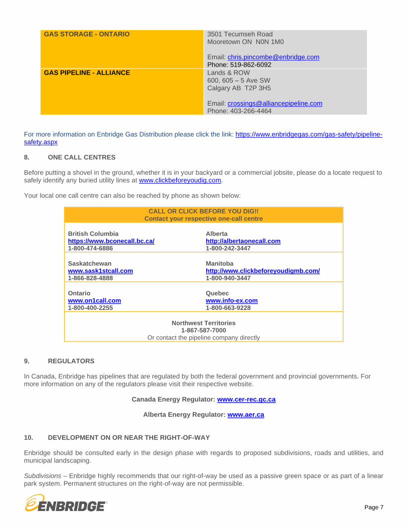
GAS STORAGE - ONTARIO 3501 Tecumseh Road Mooretown ON N0N 1M0
Email: [email protected] Phone: 519-862-6092
GAS PIPELINE - ALLIANCE Lands & ROW 600, 605 – 5 Ave SW Calgary AB T2P 3H5
Email: [email protected] Phone: 403-266-4464
Page 8
Roads and Utilities – Roads may be permitted to cross and/or run parallel to the right-of-way but no portion of a road allowance can be located on the right-of-way (apart from approved road crossings). Enbridge will review the location of utilities which are often proposed within the road allowance. Landscaping – Projects such as pedestrian pathways may be permitted as long as they do not impede Enbridge’s access along its right-of-way for operational and/or maintenance activities. Enbridge’s written consent will specify the permitted landscaping requirements. 11. DAMAGE PREVENTION Enbridge’s underground facilities must be positively identified, to Enbridge’s satisfaction, prior to the start of any proposed construction activities. Enbridge’s representative(s) have the authority to stop work at any time due to safety, environmental or operational concerns and/or unforeseen circumstances or emergency situations. **IMMEDIATELY NOTIFY ENBRIDGE IF YOU COME INTO CONTACT WITH THE PIPE! ** As a small scratch or dent in the pipeline’s coating can impact long term safety of the pipeline and must be assessed by Enbridge. Please note that obstacles or un-approved above ground installations located on an Enbridge right-of-way, such as sheds, trailers, boats and pools can interfere with Enbridge’s access of their right-of-way. Permanent structures on the right-of-way are NOT permissible. Enbridge must be contacted before conducting any blasting activities within 300m of the pipeline right-of-way so that Enbridge can review the proposed plans in order to see if there might be potential impacts to its facilities. Blasting activities related to prospecting for mines and minerals within 40m of a federally regulated pipeline right-of-way requires permission from the Canada Energy Regulator. 12. EMERGENCY SITUATIONS In an emergency situation please provide as much notice, as is practicable, to Enbridge prior to commencement of any construction, excavation, installation or temporary crossing of existing pipelines and/or right-of-ways in order to access the emergency site. Enbridge classifies an emergency situation as:
A risk to human life; Required emergency repairs of public services; or To contain an environmental emergency.
In an emergency situation please call: 1-877-420-8800 (toll free) and/or contact your local One Call provider at the numbers listed in section 8. DISCLAIMER: THESE GUIDELINES ARE INTENDED TO PROVIDE USEFUL CROSSING APPLICATION GUIDANCE INFORMATION TO THE APPLICANT. SUBMISSION OF AN APPLICATION MEETING THE REQUIREMENTS AS SET OUT HEREIN DOES NOT CONSTITUTE WRITTEN CONSENT FROM ENBRIDGE. ALL APPLICATIONS WILL BE REVIEWED BY ENBRIDGE TO DETERMINE WHETHER THE APPLICATION WILL BE APPROVED.

THIRD PARTY CROSSING APPLICATION FORM
*Refer to Application Guidance Details v1.1Page 1
APPLICANT INFORMATION Grantee* Full Legal Name for Agreement: Regulator:
Other:
Grantee Address for Service:
Grantor/Enbridge Entity
Application by Broker/Land Consultant Yes No
Broker/Land Consultant Name:
Contact Person Name: Contact Person Phone Number:
File Number:
Broker/Land Consultant Address:
CROSSING INFORMATION Expected construction start and end date(s):
Permanent Installation
Crossing Drainage Tile Pole/Pile Installation Other
Temporary Activities
Workspace Equipment Crossing Access of ROW Geophysical Road Use Proximity Other
Location indicator including affected legal land description(s), PIN and GPS Coordinates (Latitude and Longitude Decimal Degree):
Grantor’s Affected Disposition(s) (Alberta) (i.e. PLA # or License # or Line #):
Grantee’s Field Contact Information:
Name: Phone: Email:
THIRD PARTY CROSSING APPLICATION FORM
*Refer to Application Guidance Details v1.1Page 2
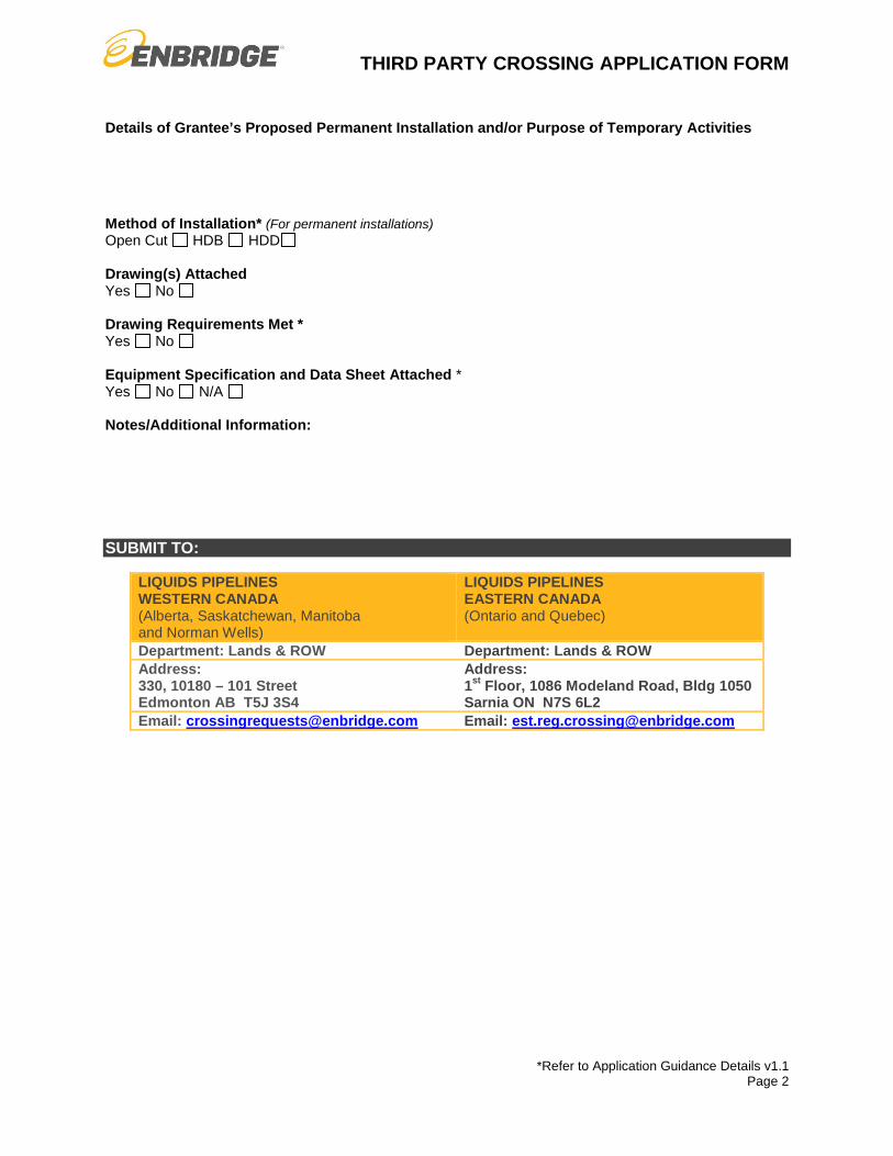
Details of Grantee’s Proposed Permanent Installation and/or Purpose of Temporary Activities
Method of Installation* (For permanent installations) Open Cut HDB HDD
Drawing(s) Attached Yes No
Drawing Requirements Met * Yes No
Equipment Specification and Data Sheet Attached * Yes No N/A
Notes/Additional Information:
SUBMIT TO:
LIQUIDS PIPELINES WESTERN CANADA (Alberta, Saskatchewan, Manitoba and Norman Wells)
LIQUIDS PIPELINES EASTERN CANADA (Ontario and Quebec)
Department: Lands & ROW Department: Lands & ROW Address: 330, 10180 – 101 Street Edmonton AB T5J 3S4
Address: 1st Floor, 1086 Modeland Road, Bldg 1050 Sarnia ON N7S 6L2
Email: [email protected] Email: [email protected]
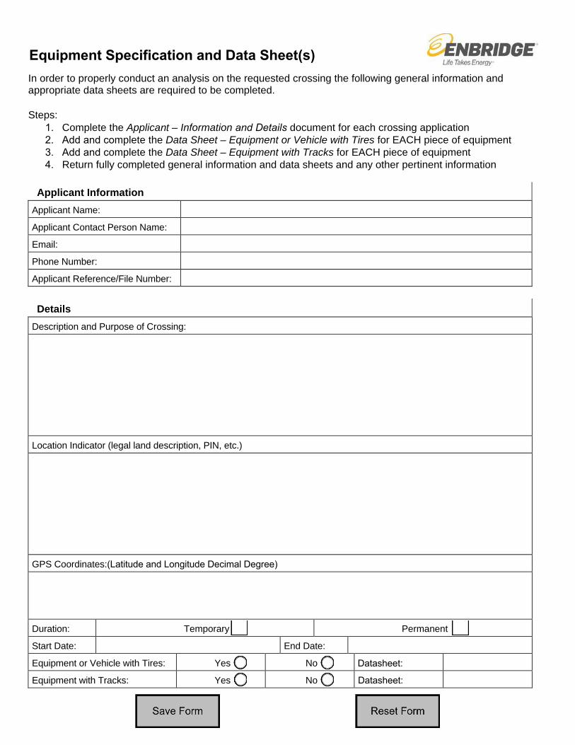
Equipment Specification and Data Sheet(s) In order to properly conduct an analysis on the requested crossing the following general information and appropriate data sheets are required to be completed.
Steps: 1. Complete the Applicant – Information and Details document for each crossing application2. Add and complete the Data Sheet – Equipment or Vehicle with Tires for EACH piece of equipment3. Add and complete the Data Sheet – Equipment with Tracks for EACH piece of equipment4. Return fully completed general information and data sheets and any other pertinent information
Applicant Information Applicant Name:
Applicant Contact Person Name:
Email:
Phone Number:
Applicant Reference/File Number:
Details Description and Purpose of Crossing:
Location Indicator (legal land description, PIN, etc.)
GPS Coordinates:(Latitude and Longitude Decimal Degree)
Duration: Temporary Permanent
Start Date: End Date:
Equipment or Vehicle with Tires: Yes No Datasheet:
Equipment with Tracks: Yes No Datasheet:

Data Sheet – Equipment with Tracks Complete this data sheet for each piece of equipment with tracks.
Equipment with Tracks INDICATE UNITS Manufacturer:
Model:
Equipment Description:
Fully Loaded Gross Vehicle Weight:
Track Shoe Width (refer to W below)
Track Length on Ground (refer to L below)
Track Gauge (on center) (refer to G below)
Units
Track
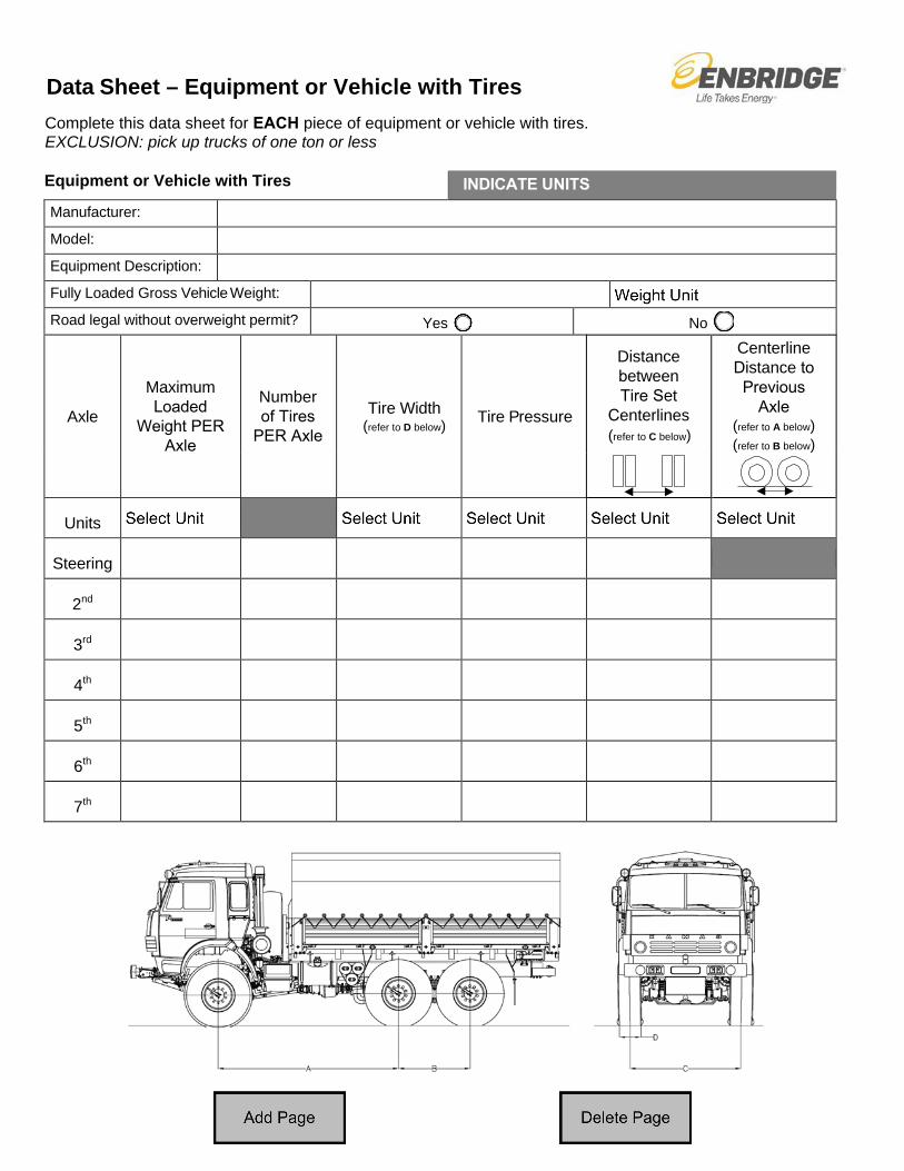
Data Sheet – Equipment or Vehicle with Tires Complete this data sheet for EACH piece of equipment or vehicle with tires. EXCLUSION: pick up trucks of one ton or less
Equipment or Vehicle with Tires INDICATE UNITSManufacturer:
Model:
Equipment Description:
Fully Loaded Gross Vehicle Weight:
Road legal without overweight permit? Yes No
Axle
Maximum Loaded
Weight PER Axle
Number of Tires
PER Axle
Tire Width (refer to D below) Tire Pressure
Distance between Tire Set
Centerlines (refer to C below)
Centerline Distance to Previous
Axle (refer to A below) (refer to B below)
Units
Steering
2nd
3rd
4th
5th
6th
7th
NO
TE:
1.EN
BRID
GE
PIPE
LIN
ES
OPE
RAT
E U
ND
ER H
IGH
PR
ESSU
RE
THER
EFO
RE
ENBR
IDG
ER
EPR
ESEN
TATI
VE(S
) MU
ST B
EPR
ESEN
T D
UR
ING
CO
NST
RU
CTI
ON
.
2.TH
IS D
RAW
ING
IS F
OR
REF
EREN
CE
ON
LY. A
CTU
AL S
ITE
DET
AILS
OR
REQ
UIR
EMEN
TS M
AYVA
RY.
2TY
PIC
AL R
OAD
CR
OSS
ING
N.T
.S.
ENBR
IDG
E PI
PE(S
) &
DIA
MET
ER
WAR
NIN
GPI
PELI
NE
SIG
N
WAR
NIN
GPI
PELI
NE
SIG
N
PROPERTY
* MIN
IMU
M C
LEAR
ANC
E:-0
.3m
IF O
PEN
CU
T AB
OVE
EN
BRID
GE
PIPE
S-0
.6m
IF O
PEN
CU
T BE
LOW
EN
BRID
GE
PIPE
LIN
ES-1
.0m
IF H
DB
UN
DER
EN
BRID
GE
PIPE
LIN
ES-3
.0m
IF H
DD
UN
DER
EN
BRID
GE
PIPE
LIN
ES
LCD
ITC
HLC
DIT
CH
LCR
OAD
WID
TH
3TY
PIC
AL F
ACIL
ITY
CR
OSS
ING
N.T
.S.
LOC
ATIO
N P
LAN
N.T
.S.
RAIL
WAY
ROAD
ENBR
IDG
E PI
PE(S
)
D
D
ENBR
IDG
E R/
W &
WID
TH
LINE
(S) N
O. &
LO
CATI
ON
SURV
EY P
IN
"D" -
TIE
DIS
TAN
CE
FRO
M
SEE
NO
TE 1
EXIS
TIN
G F
ACIL
ITY
LEG
AL D
ESCR
IPTI
ON
LEG
AL D
ESCR
IPTI
ON
LC
LC
LC
LC
ALLO
WAN
CE
21
& DI
AMET
ER
3
FORE
IGN
FACI
LITY
0.9mMIN.
1.2mMIN.
0.9mMIN.
LINE
PROPERTYLINE
TYPI
CAL
OVE
R ("
O")
CR
OSS
ING
TYPI
CAL
UN
DER
("U
") C
RO
SSIN
G
FOR
EIG
N F
ACIL
ITY
DEPTH(VARIES)
FOR
EIG
N F
ACIL
ITY
ENBR
IDG
E PI
PE(S
)&
DIA
MET
ER
* SEEBELOW
DEPTH(VARIES)
ENBR
IDG
E PI
PE(S
)&
DIA
MET
ER
TER
MIN
AL B
OX
CAT
HO
DIC
TES
T LE
ADS
FOR
EIG
N P
IPE(
S) &
DIA
MET
ER
DEPTH
ENBR
IDG
E PI
PE(S
)&
DIA
MET
ER
0.3mMIN.
(STE
EL P
IPEL
INES
)
TYPI
CAL
TES
T LE
AD C
ON
NEC
TIO
NN
.T.S
.D
WG
NO
.:R
EV N
O:
ENG
. :
SCAL
E:
CH
K:
DAT
E:
BY:
ENB
APP
R:
STAT
US:
CO
PYR
IGH
T ©
TH
IS D
RAW
ING
IS T
HE
PRO
PER
TY O
F EN
BRID
GE
AND
SH
ALL
NO
T BE
REP
RO
DU
CED
EITH
ER IN
WH
OLE
OR
IN P
ART
WIT
HO
UT
PRIO
R W
RIT
TEN
CO
NSE
NT
OF
ENBR
IDG
E.
.......0 00
TYP
ICAL
CR
OSS
ING
DET
AILS
FO
R T
HIR
D P
ARTY
APP
LIC
ANTS
CR
OSS
ING
EN
BRID
GE
PIPE
LIN
ES C
ANAD
A
B-1.
02-5
052-
03
ME
EH
HC
FRO
ST G
AFAU
LDER
30 A
UG
88
NTS
AS B
UIL
T
DES
CR
IPTI
ON
NO
BYR
EVIS
ION
REV
CH
KAP
PRD
ATE
1R
EVIS
ED A
S PE
R O
PER
ATIO
NS
INFO
RM
ATIO
N05
MAY
10
2R
EDR
AWN
FR
OM
C-1
.02-
5052
-0-0
& R
EVIS
ED A
S PE
R S
TAN
DAR
DS
UPD
ATE
08 A
PR 1
3M
DD
RD
/TD
DR
D/T
D
3AS
BU
ILT
INTE
RN
ATL
DR
AFTI
NG
IDR
434
02 A
UG
18
JZBL
BEN
B
REF
EREN
CE
DR
AWIN
GS
ON
SPU
R L
INE
MIN
IMU
M C
OVE
R F
RO
M B
ASE
OF
RAI
LWAY
1.3
m A
ND
0.8
m IN
DIT
CH
ES.
NO
TE:
1TY
PIC
AL M
AIN
LIN
E R
AILW
AY C
RO
SSIN
GN
.T.S
.
WAR
NIN
GPI
PELI
NE
SIG
NLC
DIT
CH
LCD
ITC
HC
RAI
LWAY
WID
TH L
R/W BDY
LIN
E H
EAVY
WAL
L PI
PE
ENBR
IDG
E P
IPE(
S) &
DIA
MET
ER
R/W BDY
15.0
m M
IN. A
T R
IGH
T AN
GLE
S
PIPE
LIN
E PI
PE
WAR
NIN
GPI
PELI
NE
SIG
N
"B"
*SEEBELOW
"A"
* MIN
IMU
M C
LEAR
ANC
E:"A
"C
ASED
UN
CAS
ED
"B"
0.91
m1.
83m
1.68
m3.
05m

DESCRIPTIONNO. BY
REVISIONREV
CHK APPR.
DATE
1
AS BUILT INTERNAL DRAFTING ID 304 20 MAR 18
BLB
GB ENBRIDGE
2
FRENCH TRANSLATION REFERENCE
AS PER IDR 583
2019 JAN 11
MM
BLB ENB
REFERENCE DRAWINGS
A-1.8-43105-0 TYPICAL DESIGN DETAIL
DWG. NO.:
REV. NO:
ENG. :
SCALE:
CHK:
DATE:
BY: ENB APPR:
STATUS:
COPYRIGHT © THIS DRAWING IS THE PROPERTY OF ENBRIDGE AND SHALL NOT BE REPRODUCED EITHER IN WHOLE
OR IN PART WITHOUT PRIOR WRITTEN CONSENT OF ENBRIDGE.
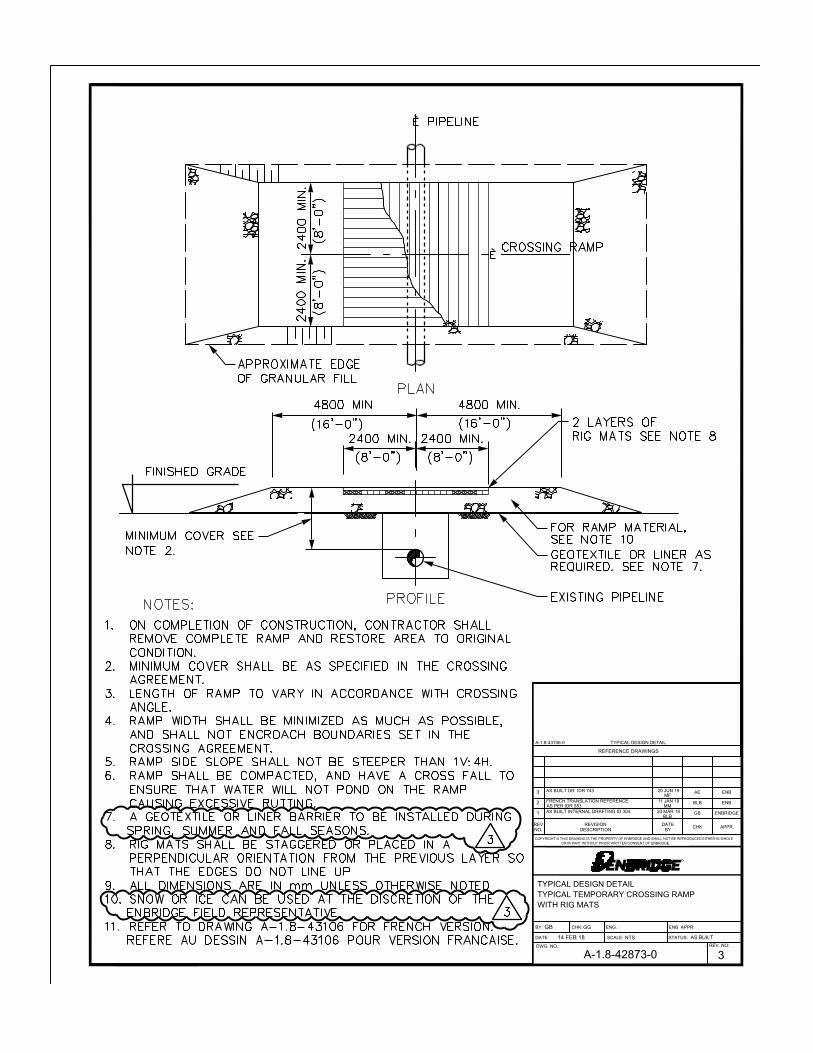
TYPICAL DESIGN DETAIL
TYPICAL TEMPORARY CROSSING RAMP WITH EARTH
A-1.8-42872-02
GB GG
14 FEB 18 NTSAS BUILT
DESCRIPTIONNO. BY
REVISIONREV
CHK APPR.
DATE
1
AS BUILT INTERNAL DRAFTING ID 304 20 MAR 18
BLB
GB ENBRIDGE
2
FRENCH TRANSLATION REFERENCE
AS PER IDR 583
11 JAN 19
MM
BLB ENB
3
AS BUILT DR IDR 743 20 JUN 19
MF
AE ENB
REFERENCE DRAWINGS
A-1.8-43106-0 TYPICAL DESIGN DETAIL
DWG. NO.:
REV. NO:
ENG. :
SCALE:
CHK:
DATE:
BY: ENB APPR:
STATUS:
COPYRIGHT © THIS DRAWING IS THE PROPERTY OF ENBRIDGE AND SHALL NOT BE REPRODUCED EITHER IN WHOLE
OR IN PART WITHOUT PRIOR WRITTEN CONSENT OF ENBRIDGE.
TYPICAL DESIGN DETAIL
TYPICAL TEMPORARY CROSSING RAMP
WITH RIG MATS
A-1.8-42873-03
GB GG
14 FEB 18 NTS AS BUILT


