
Electrical Power Utilization 10EE72
Department of EEE, SJBIT Page 1
ELECTRICAL POWER UTILIZATION
Subject Code : 10EE72 IA Marks : 25
No. of Lecture Hrs./ Week : 04 Exam Hours : 03
Total No. of Lecture Hrs. : 52 Exam Marks : 100
PART - A UNIT – 1 HEATING AND WELDING: Advantages and methods of electric of heating, resistance ovens, induction heating, dielectric heating, the arc furnace, heating of building. Electric welding, resistance and arc welding, control devices and welding equipment. 10 Hours
UNIT – 2 ELECTROLYTICPROCESS: Fundamental principles, extraction, refining of metals and electroplating. Factors affecting electro deposition process, power supply for electrolytic process. 06 Hours
UNIT - 3 & 4 ILLUMINATION: Laws of illumination, lighting calculation, factory lighting, flood lighting, street lighting, different types of lamps-incandescent, fluorescent, vapour, CFL and LED lamps and their working, comparison, Glare and its remedy. 12 Hours
PART – B
UNIT - 5, 6 & 7
ELECTRIC TRACTION: Introduction, requirements of an ideal traction, systems of traction, speed
time curve, tractive effort, co-efficient of adhesion, selection of traction motors, method of speed control, energy saving by series parallel control, ac traction equipment. AC series motor characteristics, regenerative braking, linear induction motor and their use. AC traction, diesel electric equipment, trains lighting system,
Specific energy, factors affecting specific energy consumption. 20 Hours
UNIT - 8
INTRODUCTION TO ELECTRIC AND HYBRID VEHICLES: Configuration and performance of
electrical vehicles, traction motor characteristics, tractive effort, transmission requirement, vehicle performance and energy consumption. 6 Hours
TEXT BOOKS: 1. Utilization Of Electric Energy,E Openshaw Taylor, 12th Impression,2009,Universities Press. 2. Modern Electric, Hybrid Electric and Fuel Cell Vehicles, Mehrdad, Ehsani, Yimin Gao, Sabastien. E. Gay, Ali Emadi- CRC Press.
REFERENCE BOOKS:
1. A Course in Electrical Power, Soni Gupta and Bhatnager-Dhanapat Rai & sons.
3. Electrical Power, Dr. S.L.Uppal, Khanna Publications
Search ON Google "EME Technologies"

Electrical Power Utilization 10EE72
Department of EEE, SJBIT Page 2
Sl.no Contents Page
number
1 Unit-1: Heating And Welding 4 to 73
Advantages
Resistance ovens
Induction heating
Dielectric heating,
The arc furnace
Heating of building
Electric welding
Resistance and arc welding
Control devices and welding equipment
2 Unit-2 : Electrolytic Process 74 to 83
Defination
Fundamental Principle
Extraction
Refining of metals
Electrodeposition
Power supply for electrolytic process
3 Unit-3 & 4 : Illumination 84 to 113
Laws of illumination
Lighting calculation
Factory lighting, flood lighting, street lighting
Different types of lamps-incandescent, fluorescent,
vapor, CFL and LED lamps and their working
Glare and its remedy
Comparison
4 Unit-5,6 &7:Electric Traction 114 to 158
Introduction
Requirements of an ideal traction
Systems of traction
Speed time curve
Tractive effort
Co-efficient of adhesion, selection of traction motors
Method of speed control
Saving by series parallel control, ac traction equipment
AC series motor characteristics, regenerative braking
Linear induction motor and their use
AC traction, diesel electric equipment, trains lighting
system
Specific energy
Search ON Google "EME Technologies"

Electrical Power Utilization 10EE72
Department of EEE, SJBIT Page 3
Factors affecting specific energy consumption
5 Unit-8: introduction to electric and hybrid vehicles 159 to 171
Configuration and performance of electrical vehicles
Traction motor characteristics
Tractive effort
Transmission requirement
Vehicle performance and energy consumption
Search ON Google "EME Technologies"

Electrical Power Utilization 10EE72
Department of EEE, SJBIT Page 4
PART A
UNIT-1
HEATING AND WELDING:
Introduction
Electric heating is extensively used both for domestic and industrial applications. Domestic applications
include (i) room heaters (ii) immersion heaters for water heating (iii) hot plates for cooking (iv) electric
kettles (v) electric irons (vi) pop-corn plants (vii) electric ovens for bakeries and (viii) electric toasters
etc.Industrial applications of electric heating include (i) melting of metals (ii) heat treatment of metals like
annealing, tempering, soldering and brazing etc. (iii) moulding of glass (iv) baking of insulators (v)
enameling of copper wires etc.
Advantages of Electric Heating
As compared to other methods of heating using gas, coal and fire etc., electric heating is far superior for
the following reasons:
(i) Cleanliness. Since neither dust nor ash is produced in electric heating, it is a clean system of
heating requiring minimum cost of cleaning. Moreover, the material to be heated does not get
contaminated.
(ii) No Pollution. Since no flue gases are produced in electric heating, no provision has to be made for
their exit.
(iii) Economical. Electric heating is economical because electric furnaces are cheaper in their initial cost
as well as maintenance cost since they do not require big space for installation or for storage of coal and
wood. Moreover, there is no need to construct any chimney or to provide extra heat installation.
(iv) Ease of Control. It is easy to control and regulate the temperature of an electric furnace with the
help of manual or automatic devices. Temperature can be controlled within ± 5°C which is not possible in
any other form of heating.
Search ON Google "EME Technologies"

Electrical Power Utilization 10EE72
Department of EEE, SJBIT Page 5
(v) Special Heating Requirement. Special heating requirements such as uniform heating of a material
or heating one particular portion of the job without affecting its other parts or heating with no oxidation
can be met only by electric heating.
(vi) Higher Efficiency. Heat produced electrically does not go away waste through the chimney and
other by-products. Consequently, most of the heat produced is utilised for heating the material itself.
Hence, electric heating has higher efficiency as compared to other types of heating.
(vii) Better Working Conditions. Since electric heating produces no irritating noises and also the
radiation losses are low, it results in low ambient temperature. Hence, working with electric furnaces is
convenient and cool.
(viii) Heating of Bad Conductors. Bad conductors of heat and electricity like wood, plastic and bakery
items can be uniformly and suitably heated with dielectric heating process.
(ix) Safety. Electric heating is quite safe because it responds quickly to the controlled signals. (x) Lower
Attention and Maintenance Cost. Electric heating equipment generally will not require much attention and
supervision and their maintenance cost is almost negligible. Hence, labour charges are negligibly small as
compared to other forms of heating.
Different Methods of Heat Transfer
The different methods by which heat is transferred from a hot body to a cold body are as under:
1. Conduction
In this mode of heat transfer, one molecule of the body gets heated and transfers some of the heat to the
adjacent molecule and so on. There is a temperature gradient between the two ends of the body being
heated.
Consider a solid material of cross-section A sq.m. and thickness x metre as shown in Fig. 1.1
If T1 and T2 are the temperatures of the two sides of the slab in °K, then heat conducted between the two
opposite faces in time t seconds is given by:
Where K is thermal conductivity of the material
Search ON Google "EME Technologies"

Electrical Power Utilization 10EE72
Department of EEE, SJBIT Page 6
2. Convection In this process, heat is transferred by the flow of hot and cold air currents. This process is applied in the
heating of water by immersion heater or heating of buildings. The quantity of heat absorbed by the body
by convection process depends mainly on the temperature of the heating element above the surroundings
and upon the size of the surface of the heater. It also depends, to some extent, on the position of the heater.
The amount of heat dissipated is given by
H = a (T1 – T2), where a and b are constants and T1 and T2 are the temperatures of the heating surface and
the fluid in °K respectively.
In electric furnaces, heat transferred by convection is negligible
Fig1.1
It is the transfer of heat from a hot body to a cold body in a straight line without affecting the intervening
medium. The rate of heat emission is given by Stefan‘s law according to which Heat
dissipated where K is radiating efficiency
and e is known as emissivity of the heating element.
If d is the diameter of the heating wire and l its total length, then its surface area from which heat is
ra d l. If H is the power radiated per m2 of the heating surface, then total power radiated as
heat = H d l P is the electrical power input to the heating element, then P dl H.
Methods of Electric Heating
Search ON Google "EME Technologies"

Electrical Power Utilization 10EE72
Department of EEE, SJBIT Page 7
Basically, heat is produced due to the circulation of current through a resistance. The current may circulate
directly due to the application of potential difference or it may be due to induced eddy currents. Similarly,
in magnetic materials, hysteresis losses are used to create heat. In dielectric heating, molecular friction is
employed for heating the substance. An arc established between an electrode and the material to be heated
can be made a source of heat. Bombarding the surface of material by high energy particles can be used to
heat the body.
Different methods of producing heat for general industrial and domestic purposes may be classified below:
Resistance Heating
It is based on the I2R effect. When current is passed through a resistance element I2R loss takes place
which produces heat. There are two methods of resistance heating.
(a) Direct Resistance Heating. In this method the material (or charge) to be heated is treated as a
resistance and current is passed through it. The charge may be in the form of powder, small solid pieces or
liquid. The two electrodes are inserted in the charge and connected to either a.c. or d.c. supply (Fig. 1.2).
Obviously, two electrodes will be required in the case of d.c. or single-phase a.c. supply but there would
be three electrodes in the case of 3-phase supply. When the charge is in the form of small pieces, a powder
of high resistivity material is sprinkled over the surface of the charge to avoid direct short circuit.
Search ON Google "EME Technologies"

Electrical Power Utilization 10EE72
Department of EEE, SJBIT Page 8
Heat is produced when current passes through it. This method of heating has high efficiency because the
heat is produced in the charge itself.
Fig1.2
Indirect Resistance
Heating. In this method of heating, electric current is passed through a resistance element which is placed
in an electric oven. Heat produced is proportional to I2R losses in the heating element. The heat so
produced is delivered to the charge either by radiation or convection or by a combination of the two.
Sometimes, resistance is placed in a cylinder which is surrounded by the charge placed in the jacket as
shown in the Fig. 1.3. This arrangement provides uniform temperature. Moreover, automatic temperature
control can also be provided.
Search ON Google "EME Technologies"

Electrical Power Utilization 10EE72
Department of EEE, SJBIT Page 9
Fig1.3
Requirement of a Good Heating Element
Indirect resistance furnaces use many different types of heating elements for producing heat. A good
heating element should have the following properties :
(1) High Specific Resistance.When specific resistance of the material of the wire is high,
only short length of it will be required for a particular resistance (and hence heat) or for the
same length of the wire and the currrent, heat produced will be more.
(2) High Melting Temperature. If the melting temperature of the heating element is high, it
would be possible to obtain higher operating temperatures.
(3) Low Temperature Coefficient of Resistance. In case the material has low temperature
coefficient of resistance, there would be only small variations in its resistance over its
normal range of temperature. Hence, the current drawn by the heating element when cold (i.e.,
at start) would be practically the same when it is hot.
(4) Oxidising Temperature. Oxidisation temperature of the heating element should be high
in order to ensure longer life.
Search ON Google "EME Technologies"

Electrical Power Utilization 10EE72
Department of EEE, SJBIT Page 10
(5) Positive Temperature Coefficient of Resistance. If the temperature coefficient of the
resistance of heating element is negative, its resistance will decrease with rise in temperature
and it will draw more current which will produce more wattage and hence heat. With more heat,
the resistance will decrease further resulting in instability of operation.
(6) Ductile. Since the material of the heating elements has to have convenient shapes and
sizes, it should have high ductility and flexibility.
(7) Mechanical Strength. The material of the heating element should posses high
mechanical strength of its own. Usually, different types of alloys are used to get different
operating temperatures. For example maximum working temperature of constant an (45% Ni,
55% Cu) is 400°C, that of nichrome (50%, Ni 20% Cr) is 1150°C, that of Kantha (70% Fe, 25%
Cr, 5% Al) is 1200° C and that of silicon carbide is 1450°C.
With the passage of time, every heating element breaks open and becomes unserviceable.
Some of the factors responsible for its failure are :
(1) Formation of hot spots which shine brighter during operation, (2) Oxidation (3)
Corrosion (4) Mechanical failure
Resistance Furnaces or Ovens
These are suitably-insulated closed chambers with a provision for ventilation and are used for a
wide variety of purposes including heat treatment of metals like annealing and hardening etc.,
stoving of enamelled wares, drying and baking of potteries, vulcanizing and hardening of
synthetic materials and for commercial and domestic heating. Temperatures upto 1000°C can be
obtained by using heating elements made of nickel, chromium and iron. Ovens using heating
elements made of graphite can produce temperatures upto 3000°C. Heating elements may
consist of circular wires or rectangular ribbons. The ovens are usually made of a metal
framework having an internal lining of fire bricks. The heating element may be located on the
top, bottom or sides of the oven. The nature of the insulating material is determined by the
maximum temperature required in the oven.
An enclosure for charge which is heated by radiation or convection or both is called a heating chamber.
Temperature Control of Resistance Furnaces
Search ON Google "EME Technologies"

Electrical Power Utilization 10EE72
Department of EEE, SJBIT Page 11
The temperature of a resistance furnace can be changed by controlling the I2R or V
2/R losses.
Following different methods are used for the above purpose :
(1) Intermittent Switching. In this case, the furnace voltage is switched ON and OFF
intermittently. When the voltage supply is switched off, heat production within the surface is
stalled and hence its temperature is reduced. When the supply is restored, heat production
starts and the furnace temperature begins to increase. Hence, by this simple method, the
furnace temperature can be limited between two limits.
(2) By Changing the Number of
Heating Elements. In this case, the number of heating elements is changed without cutting off
the supply to the entire furnace. Smaller the number of heating elements, lesser the heat
produced. In the case of a 3-phase circuit, equal number of heating elements is switched off
from each phase in order to maintain a balanced load condition.
(3) Variation in Circuit Configuration. In the case of 3-phase secondary load, the heating
elements give less heat when connected in a star than when connected in delta because in the
two cases, voltages across the elements is different (Fig.1.4). In single-phase circuits, series
and parallel grouping of the heating elements causes change in power dissipation resulting in
change of furnace temperature.
Search ON Google "EME Technologies"

Electrical Power Utilization 10EE72
Department of EEE, SJBIT Page 12
As shown in Fig. 47.5 heat produced is more when all these elements are connected in parallel than
when they are connected in series or series-parallel.
(4) Change of Applied Voltage. (a) Obviously, lesser the magnitude of the voltage applied to
the load, lesser the power dissipated and hence, lesser the temperature produced. In the case
of a furnace transformer having high voltage primary, the tapping control is kept in the
primary winding because the magnitude of the primary current is less. Consider the multi-tap
step-down transformer shown in Fig. 1.6.
Fig1.5 Fig1.6
(b) Bucking-Boosting the Secondary Voltage. In this method, the transformer secondary is
wound in two sections having unequal number of turns. If the two sections are connected in
series aiding, the secondary voltage is boosted i.e., increased to (E2 + E3) as shown in Fig.1.7
(a).
Search ON Google "EME Technologies"

Electrical Power Utilization 10EE72
Department of EEE, SJBIT Page 13
When the two sections are connected in series-opposing [Fig. 1.7 (b)] the secondary voltage is
reduced i.e., there is bucking effect. Consequently, furnace voltage becomes (E2 – E3) and,
hence, furnace temperature is reduced.
(c) Autotransformer Control. Fig. 47.8 shows the use of tapped autotransformer used for
decreasing the furnace voltage and, hence, temperature of small electric furnaces. The required
voltage can be selected with the help of a voltage selector.
(d) Series Reactor Voltage. In this case, a heavy-duty core-wounded coil is
placed in series with the furnace as and when desired. Due to drop in voltage
across the impedance of the coil, the voltage available across the furnace is
reduced. With the help of D.P.D.T. switch, high/low, two mode temperature
control can be obtained as shown in the Fig. 47.9. Since the addition of series coil
reduces the power factor, a power capacitor is simultaneously introduced in the
circuit for keeping the p.f. nearly unity. As seen, the inductor is connected in
series, whereas the capacitor is in parallel with the furnace.
Design of Heating Element
Normally, wires of circular cross-section or rectangular conducting ribbons are used as heating
elements. Under steady-state conditions, a heating element dissipates as much heat from its
surface as it receives the power from the electric supply. If P is the power input and H is the
heat dissipated by radiation, then P = H under steady-state conditions.
As per Stefan‘s law of radiation, heat radiated by a hot body is given by
where T1 is the temperature of hot body in °K and T2 that of the cold body (or cold surroundings)
in °K
Search ON Google "EME Technologies"

Electrical Power Utilization 10EE72
Department of EEE, SJBIT Page 14
Total surface area of the wire of the element = (∏d) × l……………………………….i
If H is the heat dissipated by radiation per second per unit surface area of the wire, then heat
radiated per second = (∏d) × l × H……………ii
Equating (i) and (ii), we have
…………………iii
We can find the values of l and d from Eq. (i) and (iii) given above.
Ribbon Type Element
If w is the width of the ribbon and t its thickness, then
…………………………
….iv
Heat lost from ribbon surface = 2wl H (neglecting the side area 2tl )
………………………………v
Values of l and w for a given ribbon of thickness t can be found from Eqn. (iv) and (v) given above.
Arc Furnaces
If a sufficiently high voltage is applied across an air-gap, the air becomes ionized and starts
conducting in the form of a continuous spark or arc thereby producing intense heat. When
electrodes are made of carbon/graphite, the temperature obtained is in the range of 3000°C-
Search ON Google "EME Technologies"

Electrical Power Utilization 10EE72
Department of EEE, SJBIT Page 15
3500C. The high voltage required for striking the arc can be obtained by using a step-up
transformer fed from a variable a.c. supply as shown in Fig. 1.10 (a).
Fig1.10
An arc can also be obtained by using low voltage across two electrodes initially in contact with
each other as shown in Fig. 1.10 (b). The low voltage required for this purpose can be obtained
by using a step-down transformer. Initially, the low voltage is applied, when the two electrodes
are in contact with each other. Next, when the two electrodes are gradually separated from each
other, an arc is established between the two.
Arc furnaces can be of the following two types :
1. Direct Arc Furnace
In this case, arc is formed between the two electrodes and the charge in such a way that
electric current passes through the body of the charge as shown in Fig. 47.11 (a). Such
furnaces produce very high temperatures.
2. Indirect Arc Furnace
In this case, arc is formed between the two electrodes and the heat thus produced is
passed on to the charge by radiation as shown in Fig. 1.11 (b).
Search ON Google "EME Technologies"

Electrical Power Utilization 10EE72
Department of EEE, SJBIT Page 16
Fig1.11
Direct Arc Furnace
It could be either of conducting-bottom type [Fig. 1.12 (a)] or non-conducting bottom type
[Fig. 1.12 (b)].As seen from Fig. 47.12 (a), bottom of the furnace forms part of the electric
circuit so that current passes through the body of the charge which offers very low resistance.
Hence, it is possible
Fig 1.12
to obtain high temperatures in such furnaces. Moreover, it produces uniform heating of charge
without stirring it mechanically. In Fig. 47.12 (b), no current passes through the body of the
furnace.
Search ON Google "EME Technologies"
Electrical Power Utilization 10EE72
Department of EEE, SJBIT Page 17
Most common application of these furnaces is in the production of steel because of the ease with
which the composition of the final product can be controlled during refining.
Most of the furnaces in general use are of non-conducting bottom type due to insulation problem
faced in case of conducting bottom.
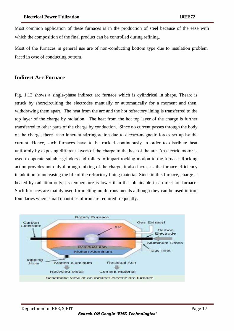
Indirect Arc Furnace
Fig. 1.13 shows a single-phase indirect arc furnace which is cylindrical in shape. Thearc is
struck by shortcircuiting the electrodes manually or automatically for a moment and then,
withdrawing them apart. The heat from the arc and the hot refractory lining is transferred to the
top layer of the charge by radiation. The heat from the hot top layer of the charge is further
transferred to other parts of the charge by conduction. Since no current passes through the body
of the charge, there is no inherent stirring action due to electro-magnetic forces set up by the
current. Hence, such furnaces have to be rocked continuously in order to distribute heat
uniformly by exposing different layers of the charge to the heat of the arc. An electric motor is
used to operate suitable grinders and rollers to impart rocking motion to the furnace. Rocking
action provides not only thorough mixing of the charge, it also increases the furnace efficiency
in addition to increasing the life of the refractory lining material. Since in this furnace, charge is
heated by radiation only, its temperature is lower than that obtainable in a direct arc furnace.
Such furnaces are mainly used for melting nonferrous metals although they can be used in iron
foundaries where small quantities of iron are required frequently.
Search ON Google "EME Technologies"

Electrical Power Utilization 10EE72
Department of EEE, SJBIT Page 18
Fig1.13
Induction Heating
This heating process makes use of the currents induced by the electro-magnetic action in the
charge to be heated. In fact, induction heating is based on the principle of transformer working.
The primary winding which is supplied from an a.c. source is magnetically coupled to the
charge which acts as a short circuited secondary of single turn. When an a.c. voltage is applied
to the primary, it induces voltage in the secondary i.e. charge. The secondary current heats up
the charge in the same way as any electric current does while passing through a resistance. If V
is the voltage induced in the charge and R is the charge resistance, then heat produced = V 2/R.
The value of current induced in the charge depends on (i) magnitude of the primary current (ii)
turn ratio of the transformer
(iii) co-efficient of magnetic coupling. Low-frequency induction furnaces are used for melting
and refining of different metals. However, for other processes like case hardening and soldering
etc., high-frequency eddy-current heating is employed. Low frequency induction furnaces
employed for the melting of metals are of the following two types :
(a) Core-type Furnaces — which operate just like a two winding transformer. These can be
further sub-divided into (i) Direct core-type furnaces (ii) Vertical core-type furnaces and (iii)
Indirect core-type furnaces.
(b) Coreless-type Furnaces — in which an inductively-heated element is made to transfer
heat to the charge by radiation.
Search ON Google "EME Technologies"

Electrical Power Utilization 10EE72
Department of EEE, SJBIT Page 19
Core Type Induction Furnace
It is shown in Fig. 1.14 and is essentially a transformer in which the charge to be heated forms a
single-turn short-circuited secondary and is magnetically coupled to the primary by an iron core.
The furnace consists of a circular hearth which contains the charge to be melted in the form of
an annular ring. When there is no molten metal in the ring, the secondary becomes open-
circuited there-by cutting off the secondary current. Hence, to start the furnace, molted metal
has to be poured in the annular hearth. Since, magnetic coupling between the primary and
secondary is very poor, it results in high leakage and low power factor. In order to nullify the
effect of increased leakage reactance, low primary frequency of the order of 10 Hz is used. If the
transformer secondary current density exceeds 500 A/cm2 then, due to the interaction of
secondary current with the alternating magnetic field, the molten metal is squeezed to the extent
that secondary circuit is interrupted. This effect is known as ―pinch effect‖.
Search ON Google "EME Technologies"

Electrical Power Utilization 10EE72
Department of EEE, SJBIT Page 20
Fig1.14
This furnace suffers from the following drawbacks:
1. It has to be run on low-frequency supply which entails extra expenditure on motor-generator set or
frequency convertor.
2. It suffers from pinching effect.
3. The crucible for charge is of odd shape and is very inconvenient for tapping the molten charge.
4. It does not function if there is no molten metal in the hearth i.e. when the secondary is open. Every time
molten metal has to be poured to start the furnace.
5. It is not suitable for intermittent service. However, in this furnace, melting is rapid and clean and
temperature can be controlled easily.
Moreover, inherent stirring action of the charge by electro-magnetic forces ensures greater uniformity of
the end product.
Vertical Core-Type Induction Furnace
It is also known as Ajax-Wyatt furnace and represents an improvement over the core-type
furnace discussed above. As shown in Fig., it has vertical channel (instead of a horizontal one)
for the charge, so that the crucible used is also vertical which is convenient from metallurgical
Search ON Google "EME Technologies"

Electrical Power Utilization 10EE72
Department of EEE, SJBIT Page 21
point of view. In this furnace, magnetic coupling is comparatively better and power factor is
high. Hence, it can be operated from normal frequency supply. The circulation of the molten
metal is kept up round the Vee portion by convection currents as shown in Fig. 1.15. As Vee
channel is narrow, even a small quantity of charge is sufficient to keep the secondary circuit
closed. However, Vee channel must be kept full of charge in order to maintain continuity of
secondary circuit.
This fact makes this furnace suitable for continuous operation. The tendency of the secondary
circuit to rupture due to pinch-effect is counteracted by the weight of the charge in the crucible.
The choice of material for inner lining of the furnace depends on the type of charge used. Clay
lining is used for yellow brass. For red brass and bronze, an alloy of magnetia and alumina or
corundum is used. The top of the furnace is covered with an insulated cover which can be
removed for charging. The furnace can be tilted by the suitable hydraulic arrangement for taking
out the molten metal.
This furnace is widely used for melting and refining of brass and other non-ferrous metals. As
said earlier, it is suitable for continuous operation. It has a p.f. of 0.8-0.85. With normal supply
frequency, its efficiency is about 75% and its standard size varies from 60-300 kW, all single-
phase.
Search ON Google "EME Technologies"

Electrical Power Utilization 10EE72
Department of EEE, SJBIT Page 22
Fig1.15
Indirect Core-Type Induction Furnace
In this furnace, a suitable element is heated by induction which, in turn, transfers the heat to the
charge by radiation. So far as the charge is concerned, the conditions are similar to those in a
resistanceoven.
As shown in Fig. 1.16, the secondary consists of a metal container which forms the walls of the
furnace proper. The primary winding is magnetically coupled to this secondary by an iron core.
When primary winding is connected to a.c. supply, secondary current is induced in the metal
container by transformer action which heats up the container. The metal container transfers this
heat to the charge. A special advantage of this furnace is that its temperature can be
automatically controlled without the use of an external equipment. The part AB of the magnetic
circuit situated inside the oven chamber consists of a special alloy which loses its magnetic
properties at a particular temperature but regains them when cooled back to the same
temperature. As soon as the chamber attains the critical temperature, reluctance of the magnetic
circuit increases manifold thereby cutting off the heat supply. The bar AB is detachable and can
be replaced by other bars having different critical temperatures.
Coreless Induction Furnace
As shown in Fig. 1.17, the three main parts of the furnace are (i) primary coil (ii) a ceramic
crucible containing charge which forms the secondary and (iii) the frame which includes
supports and tilting mechanism. The distinctive feature of this furnace is that it contains no
heavy iron core with the result that there is no continuous path for the magnetic flux. The
crucible and the coil are relatively light in construction and can be conveniently tilted for
pouring. The charge is put into the crucible and primary winding is connected to a high-
frequency a.c. supply. The flux produce by the primary sets up eddy-currents in the charge and
heats it up to the melting point. The charge need not be in the molten state at the start as was
required by core-type furnaces. The eddy- currents also set up electromotive forces which
produce stirring action which is essential for obtaining uniforms quality of metal. Since flux
Search ON Google "EME Technologies"

Electrical Power Utilization 10EE72
Department of EEE, SJBIT Page 23
density is low (due to the absence of the magntic core) high frequency supply has to be used
because eddy-current loss We However, this high frequency increases the resistance of the
primary winding due to skin effect, thereby increasing primary Cu losses. Hence, the primary
winding is not made of Cu wire but consists of hollow Cu tubes which are cooled by water
circulating through them. Since magnetic coupling between the primary and secondary windings
is low, the furnace p.f. lies between 0.1 and 0.3. Hence, static capacitors are invariably used in
parallel with the furnace to improve its p.f.
Fig1.16
Such furnaces are commonly used for steel production and for melting of non-ferrous metals
like brass, bronze, copper and aluminium etc., along with various alloys of these elements.
Special application of these furnaces include vacuum melting, melting in a controlled
atmosphere and melting for precision casting where high frequency induction heating is used. It
also finds wide use in electronic industry and in other industrial activities like soldering, brazing
hardening and annealing and sterilizing surgical instruments etc. Some of the advantages of
coreless induction furnaces are as follows :
(1) They are fast in operation.
(2) They produce most uniform quality of product.
(3) They can be operated intermittenly.
(4) Their operation is free from smoke, dirt, dust and noises.
(5) They can be used for all industrial applications requiring heating and melting.
(6) They have low erection and operating costs.
(7) Their charging and pouring is simple.
Search ON Google "EME Technologies"

Electrical Power Utilization 10EE72
Department of EEE, SJBIT Page 24
Fig1.17
High Frequency Eddy-current Heating
For heating an article by eddy-currents, it is placed inside a high frequency a.c. current-carrying
coil (Fig. 1.18). The alternating magnetic field produced by the coil sets up eddy-currents in the
article which, consequently, gets heated up. Such a coil is known as heater coil or work coil and
the material to be heated is known as charge or load. Primarily, it is the eddy-current loss which
is responsible for the production of heat although hysteresis loss also contributes to some extent
in the case of non-magnetic materials.
Search ON Google "EME Technologies"

Electrical Power Utilization 10EE72
Department of EEE, SJBIT Page 25
Fig1.18 The eddy-current loss We α B
2f2. Hence, this loss can be controlled by controlling flux density
B and the supply frequency ƒ. This loss is greatest on the surface of the material but decreases
as we go deep inside. The depth of the material upto which the eddy-current loss penetrates is
given by
Advantages of Eddy-current Heating
(1) There is negligible wastage of heat because the heat is produced in the body to be heated.
(2) It can take place in vacuum or other special environs where other types of heating are not possible.
(3) Heat can be made to penetrate any depth of the body by selecting proper supply frequently.
Applications of Eddy-current Heating
(1) Surface Hardening. The bar whose surface is to be hardened by heat treatment is placed
within the working coil which is connected to an a.c. supply of high frequency. The depth upto
which the surface is to be hardened can be obtained by the proper selection of frequency of the
coil current. After a few seconds, when surface has reached the proper temperature, a.c. supply
is cut off and the bar is at once dipped in water.
(2) Annealing. Normally, annealing process takes long time resulting in scaling of the metal
which is undesirable. However, in eddy-current heating, time taken is much less so that no scale
formation takes place.
(3) Soldering. Eddy-current heating is economical for precise high-temperature soldering
where silver, copper and their alloys are used as solders.
Dielectric Heating
Search ON Google "EME Technologies"

Electrical Power Utilization 10EE72
Department of EEE, SJBIT Page 26
It is also called high-frequency capacitative heating and is used for heating insulators like wood,
plastics and ceramics etc. which cannot be heated easily and uniformly by other methods. The
supply frequency required for dielectric heating is between 10-50 MHz and the applied voltage
is upto 20 kV. The overall efficiency of dielectric heating is about 50%.
Dielectric Loss
When a practical capacitor is connected across an a.c. supply, it draws a current which leads the
voltage by an angle , which is a little less than 90° or falls short of 90° by an angle δ. It means
that there is a certain component of the current which is in phase with the voltage and hence
produces some loss called dielectric loss. At the normal supply frequency of 50 Hz, this loss is
negligibly small but at higher frequencies of 50 MHz or so, this loss becomes so large that it is
sufficient to heat the dielectric in which it takes place. The insulating material to be heated is
placed between two conducting plates in order to form a parallel-plate capacitor as shown in
Fig. 1.19 (a).
Fig1.19
Fig. 1.19 (b) shows the equivalent circuit of the capacitor and Fig. 1.19 (c) gives its vector diagram.
the surface area of the dielectric slab. This power is where d is the thickness and A is
converted into heat. Since for a given insulator material, C and δ are
constant, the dielectric loss is directly proportional to V 2 f. That is why
high-frequency voltage is used in dielectric heating. Generally, a.c. voltage of about 20 kV at a
frequency of 10-30 MHz is used.
Advantages of Dielectric Heating
Search ON Google "EME Technologies"

Electrical Power Utilization 10EE72
Department of EEE, SJBIT Page 27
1. Since heat is generated within the dielectric medium itself, it results in uniform heating.
2. Heating becomes faster with increasing frequency.
3. It is the only method for heating bad conductors of heat.
4. Heating is fastest in this method of heating.
5. Since no naked flame appears in the process, inflammable articles like plastics and wooden products
etc., can be heated safely.
6. Heating can be stopped immediately as and when desired
Applications of Dielectric Heating
Since cost of dielectric heating is very high, it is employed where other methods are not possible or
are too slow. Some of the applications of dielectric heating are as under:
1. For gluing of multilayer plywood boards.
2. For baking of sand cores which are used in the moulding process.
3. For preheating of plastic compounds before sending them to the moulding section.
4. For drying of tobacco after glycerine has been mixed with it for making cigarattes.
5. For baking of biscuits and cakes etc. in bakeries with the help of automatic machines.
6. For electronic sewing of plastic garments like raincoats etc. with the help of cold rollers fed with high-
frequency supply.
7. For dehydration of food which is then sealed in air-tight containers.
8. For removal of moistures from oil emulsions.
9. In diathermy for relieving pain in different parts of the human body.
10. For quick drying of glue used for book binding purposes.
Search ON Google "EME Technologies"

Electrical Power Utilization 10EE72
Department of EEE, SJBIT Page 28
Choice of Frequency
The selection of frequency for heating is important because it has a great bearing on the work to
be heated and the method of its heating whether by induction heating or dielectric heating.
Furnaces running on power frequency of 50 Hz can be of 1 MW capacity whereas those running
on medium frequencies (500 Hz to 1000 Hz) have a capacity of 50 kW and those running on
high frequency (1 MHz to 2 MHz) have capacities ranging from 200 kW to 500 kW.
1. Induction Heating. While choosing frequency for induction heating, the following factors are
considered :
(a) Thickness of the surface to be heated. Higher the frequency, thinner the surface that will get
heated.
(b) The time of continuous heating. Longer the duration of heating, deeper the penetration of heat in
the work due to conduction.
(c) The temperature to be obtained. Higher the temperature, higher the capacity of the generator
required.
Dielectric Heating. The power consumed during dielectric heating,
P = 2 f CV2co s . As seen, P α f × C × V2 × cos . Hence, rate of heat production can
be increased by increasing voltage or voltage across any specimen is limited by its thickness or
because of the consideration of potential gradient, breakdown voltage and safety etc., Voltages
ranging from 600 V to 3000 V are used for dielectric heating, although voltages of 20 kV or so
are also used sometimes. Rate of heat production can also be increased by applying high
potential but it is also limited because of the following considerations: (a) Possibility of
formation of standing waves between the surface of two electrodes having wavelength nearly
equal to or more than one quarter of the wavelength of the particular frequency used.
(b) Necessity of employing special matching circuit at higher frequencies due to the fact that
maximum power transfer takes place when the oscillator impedence equals the load impedence.
(c) At higher frequencies it is difficult for tuning inductance to resonate with the charge capacitance.
(d) At higher frequencies, it is almost impossible to get uniform voltage distribution.
Search ON Google "EME Technologies"

Electrical Power Utilization 10EE72
Department of EEE, SJBIT Page 29
(e) Since higher frequencies disturb near-by radio station services, special arrangement has to be made to
stop radiations from the high-frequency generator used for the purpose.
When tungsten filament lamps are operated at about 2300°C (instead of 3000°C), they produce
plenty of heat radiations called infrared radiations. With the help of suitable reflectors, these
infrared radiations are focused on the surface to be heated. The lamps so employed have ratings
varying from 250 W to 1000 W operating at 115 W. Lower voltage results in robust filaments.
With this arrangement, the charge temperature obtain is between 200°C and 300°C. The heat
emission intensity obtained is about 7000 W/m2 as compared to 1500 W/m2 obtained with
ordinary resistance furnaces. In this type of heating, heat absorption remains practically constant
whatever the charge temperature whereas it falls rapidly as the temperature of charge rises in the
ordinary resistance furnace. Infrared heating is used for paint drying and for drying foundary
moulds, for low temperature heating of plastics and for various dehydration and other processes.
ELECTRIC WELDING
Definition of Welding
It is the process of joining two pieces of metal or non-metal at faces rendered plastic or liquid by the
application of heat or pressure or both. Filler material may be used to effect the union.
Welding Processes
All welding processes fall into two distinct categories:
1. Fusion Welding—It involves melting of the parent metal. Examples are:
(i) Carbon arc welding, metal arc welding, electron beam welding, electroslag welding and electrogas
welding which utilize electric energy and
(ii) Gas welding and thermit welding which utilize chemical energy for the melting purpose.
2. Non-fusion Welding—It does not involve melting of the parent metal. Examples are:
(i) Forge welding and gas non-fusion welding which use chemical energy.
Search ON Google "EME Technologies"

Electrical Power Utilization 10EE72
Department of EEE, SJBIT Page 30
(ii) Explosive welding, friction welding and ultrasonic welding etc., which use mechanical energy.
(iii) Resistance welding which uses electrical energy.
Proper selection of the welding process depends on the (a) kind of metals to be joined (b) cost
involved (c) nature of products to be fabricated and (d) production techniques adopted. The
principal welding processes have been tabulated in Fig. 1.20
Use of Electricity in Welding
Electricity is used in welding for generating heat at the point of welding in order to melt the
material which will subsequently fuse and form the actual weld joint. There are many ways of
producing this localised heat but the two most common methods are as follows:
1. Resistance welding—here current is passed through the inherent resistance of the joint to be
welded thereby generating the heat as per the equation I2 Rt/J kilocalories.
2. Arc welding—here electricity is conducted in the form of an arc which is established
between the two metallic surfaces
Formation and Characteristics of Electric Arc
An electric arc is formed whenever electric current is passed between two metallic electrodes
which are separated by a short distance from each other. The arc is started by momentarily
touching the positive electrode (anode) to the negative metal (or plate) and then withdrawing it
to about 3 to 6 mm from the plate. When electrode first touches the plate, a large short-circuit
current flows and as it is later withdrawn from the plate, current continues to flow in the form of
a spark across the air gap so formed. Due to this spark (or discharge), the air in the gap becomes
ionized i.e. is split into negative electrons and positive ions. Consequently, air becomes
conducting and current is able to flow across the gap in the form of an arc.
As shown in Fig. 1.22, the arc consists of lighter electrons which flow from cathode to anode
and heavier positive ions which flow from anode to cathode. Intense heat is generated when
high velocity electrons strike the anode. Heat generated at the cathode is much less because of
the low velocity of the impinging ions. It is found that nearly two-third of the heat is developed
Search ON Google "EME Technologies"

Electrical Power Utilization 10EE72
Department of EEE, SJBIT Page 31
at the anode which burns into the form of a crater where temperature rises to a value of 3500-
4000°C. The remaining one-third of the heat is developed near the cathode. The above statement
is true in all d.c. systems of welding where positive side of the circuit is the hottest side. As a
result, an electrode connected to the positive end of the d.c. supply circuit will
burn 50% faster than if connected to the negative end. This fact can be used for obtaining desired
penetration of the base metal during welding.
Fig 1.20
If positive supply end is connected to the base metal (which is normally grounded), penetration
will be greater due to more heat and, at the same time, the electrode will burn away slowly [Fig.
1.23(a)] since it is connected to the negative end of the supply. If supply connections are
reversed, the penetration of heat zone in the base metal will be comparatively shallow and, at the
same time, electrode will burn fast [Fig.1.23 (b)]. AC supply produces a penetration depth that is
Search ON Google "EME Technologies"

Electrical Power Utilization 10EE72
Department of EEE, SJBIT Page 32
early halfway between that achieved by the d.c. positive ground and negative ground as shown in
Fig.1.23(c). It may be noted that with a.c. supply, heat is developed equally at the anode and
cathode due to rapid reversal of their polarity. The arc utilized for arc welding is a low-voltage
high-current discharge. The voltage required for striking the arc is higher than needed for
maintaining it. Moreover, amperage increases as voltage decreases after the arc has been
established. Fig 1.24 shows V/I characteristics of an electric arc for increasing air-gap lengths.
The voltage required to strike a d.c. arc is about 50-55 V and that for a.c. arc is 80-90 V. The
voltage drop across the arc is nearly 15-20 V. It is difficult to maintain the arc with a voltage less
than 14 V or more than 40 V.
Fig1.22
Fig 1.23
Search ON Google "EME Technologies"

Electrical Power Utilization 10EE72
Department of EEE, SJBIT Page 33
Fig1.24
Effect of Arc Length
In metal arc welding, a fairly short arc length is necessary for getting good welds. Short arc length
permits the heat to be concentrated on the workpiece, is more stable because effect of magnetic blow is
reduced and the vapours from the arc surround the electrode metal and the molten pool thereby
preventing air from destroying the weld metal. When arc length is long
1. large amount of heat is lost into the surrounding area thus preventing good penetration and
fusion; 2. arc flame is very unstable since effect of magnetic blow is increased. Hence, arc flame
will have a tendency to blow out;
3. air is able to reach the molten globule of metal as it passes from the electrode to the weld
and weld pool. It leads to the contamination of the weld due to absorption of oxygen and
nitrogen;
4. weld deposits have low strength, poor ductility, high porosity, poor fusion and excessive
spatter. The length of arc required for welding will depend on the kind of electrode used, its
coating, its diameter, position of welding and the amount of current used. Usually, shorter arc
length are necessary for vertical, horizontal and overhead welding than for flat welding.
Search ON Google "EME Technologies"

Electrical Power Utilization 10EE72
Department of EEE, SJBIT Page 34
Arc Blow
An arc column can be considered as a flexible current-carrying conductor which can be easily deflected
by the magnetic field set up in its neighbourhood by the
positive and negative leads from the d.c. welding set. The two leads carry currents in the
opposite directions and hence, set up a repulsive magnetic force which pulls the arc away from
the weld point particularly when welding corners where field concentration is maximum. The
deflection of the arc is called arc blow. This condition is encountered only with d.c. welding
sets and is especially noticeable when welding with bare electrodes. It is experienced most when
using currents above 200 A or below 40 A. Due to arc blow, heat penetration in the required
area is low which leads to incomplete fusion and bead porosity apart from excessive weld
spatter.
Arc blow can be avoided by using a.c. rather than d.c. welding machines because reversing
currents in the welding leads produce magnetic fields which cancel each other out thereby
eliminating the arc blow. However, with d.c. welding machines, arc blow effects can be
minimized by
Search ON Google "EME Technologies"

Electrical Power Utilization 10EE72
Department of EEE, SJBIT Page 35
(i) welding away from the earth ground connection, (ii) changing the position of the earth
connection on the work, (iii) wrapping the welding electrode cable a few turns around the work,
(iv) reducing the welding current or electrode size, (v) reducing the rate of travel of the electrode
and (vi) shortening the arc column length etc.
Polarity in DC Welding
Arc welding with the electrode connected to the positive end of the d.c. supply is called reverse polarity.*
Obviously, the workpiece is connected to the negative end.
A better name for d.c. reverse polarity (DCRP) is electrode-positive as shown in Fig. 1.25(a).
As stated earlier in Art. 48.4, two-third of the arc heat is developed at the anode. Hence, in
DCRP welding, electrode is the hottest whereas work piece is comparatively cooler.
Consequently, electrode burns much faster but weld bead is relatively shallow and wide. That is
why thick and heavily coated electrodes are used in DCRP welding because they require more
heat for melting. Arc welding with the electrode connected to the negative end of the d.c. supply
is called straight polarity.** Obviously, the workpiece is connected to the positive end as
shown in Fig. 1.25 (b). A better name for d.c. straight polarity (DCSP) is electrode-negative
Fig 1.25
In DCSP welding, workpiece is the hottest, hence base metal penetration is narrow and deep.
Moreover, bare and medium-coated electrodes can be used in this welding as they require less
Search ON Google "EME Technologies"

Electrical Power Utilization 10EE72
Department of EEE, SJBIT Page 36
amount of heat for melting. It is seen from the above discussion that polarity necessary for the
welding operation is determined by the type of electrode used. It is also worth noting that in a.c.
welding, there is no choice of polarity because the circuit becomes alternately positive, first on
one side and then on the other. In fact, it is a combination of DCSP and D CRP.
Fig1.26
Four Positions of Arc Welding
There are four basic positions in which manual arc welding is done.
1. Flat position. It is shown in Fig. 1.27 (a). Of all the positions, flat position is the easiest,
most economical and the most used for all shielded arc welding. It provides the strongest weld
joints. Weld beads are exceedingly smooth and free of slag spots. This position is most
adaptable for welding of both ferrous and non-ferrous metals particularly for cast iron.
2. Horizontal Position. It is the second most popular position and is shown in Fig. 1.27(b).
It also requires a short arc length because it helps in preventing the molten puddle of the metal
from sagging. However, major errors that occur while welding in horizontal position are under-
cutting and over-lapping of the weld zone (Fig. 1.26).
3. Vertical Position. It is shown in Fig. 1.27 (c). In this case, the welder can deposit the
bead either in the uphill or downhill direction. Downhill welding is preferred for thin metals
because it is faster than the uphill welding. Uphill welding is suited for thick metals because it
produces stronger welds.
Search ON Google "EME Technologies"

Electrical Power Utilization 10EE72
Department of EEE, SJBIT Page 37
Fig 1.27
3. Overhead Position. It is shown in Fig.1.27 (d). Here, the welder has to be very cautious
otherwise he may get burnt by drops of falling metal. This position is thought to be the
most hazardous but not the most difficult one.
Electrodes for Metal Arc Welding
An electrode is a filler metal in the form of a wire or rod which is either bare or coated
uniformly with flux. As per IS : 814-1970, the contact end of the electrode is left bare and clean
to a length of 20-30 mm. for inserting it into electrode holder (Fig.
1.28)
Fig1.28
Metal arc welding was originally done with bare electrodes which consisted of a piece of wire or
rod of the same metal as the base metal. However, due to atmospheric contamination, they
produced brittle and poor quality welds. Hence, bare wire is no longer used except for automatic
welding in which case arrangement is made to protect the weld area from the atmosphere by
Search ON Google "EME Technologies"

Electrical Power Utilization 10EE72
Department of EEE, SJBIT Page 38
either powdered flux or an inert gas. Since 1929, coated electrodes are being extensively used
for shielded arc welding.
They consist of a metal core wire surrounded by a thick flux coating applied by extrusion,
winding or other processes. Depending on the thickness of the flux coating, coated electrodes
may be classified into (i) lightly-dusted (or dipped) electrodes and (ii) semi-coated (or
heavycoated) electrodes. Materials commonly used for coating are (i) titanium oxide (ii)
ferromanganese (iii) silica flour (iv) asbestos clay (v) calcium carbonate and (vi) cellulose with
sodium silicate often used to hold ingredients together.
Electrode coating contributes a lot towards improving the quality of the weld. Part of the coating
burns in the intense heat of the arc and provides a gaseous shield around the arc which prevents
oxygen, nitrogen and other impurities in the atmosphere from combining with the molten metal
to cause a poor quality brittle and weak weld. Another portion of the coating flux melts and
mixes with the impurities in the molten pool causing them to float to the top of the weld where
they cool in the form of slag (Fig. 1.29). This slag improves the bead quality by protecting it
from the contaminating effects of the atmosphere and causing it to cool down more uniformly. It
also helps in controlling the basic shape of the weld bead.
The type of electrode used depends on the type of metal to be welded, the welding position, the
type of electric supply whether a.c. or d.c. and the polarity of the welding machine.
Advantages of Coated Electrodes
The principal advantages of using electrode coating are as under :
1. It stablizes the arc because it contains ionizing agents such as compounds of sodium and potassium.
2. It fluxes away impurities present on the surface being welded.
3. It forms slag over the weld which (i) protects it from atmospheric contamination
(ii) makes it cool uniformly thereby reducing the changes of brittleness and
(iii) provides a smoother surface by reducing ‗ripples‘ caused by the welding operation.
4. It adds certain materials to the weld metal to compensate for the loss of any volatile alloying elements or
constituents lost by oxidization.
5. It speeds up the welding operation by increasing the rate of melting.
6. It prevents the sputtering of metal during welding.
Search ON Google "EME Technologies"

Electrical Power Utilization 10EE72
Department of EEE, SJBIT Page 39
7. it makes it possible for the electrode to be used on a.c. supply. In a.c. welding, arc tends to cool
and interrupt at zero-current positions. But the shielding gases produced by the flux keep the arc space
ionized thus enabling the coated electrodes to be used on a.c. supply. It is worth noting that efficiency
of all coated (or covered) electrodes is impaired by dampness. Hence, they must always be stored
in a dry space. If dampness is suspected, the electrodes should be dried in a warm cabinet for a few hours.
Types of Joints and Types of Applicable Welds
Bureau of Indian Standards (B.I.S.) has recommended the following types of joints and the welds
applicable to each one of them (Fig. 1.30).
1. Tee joint — with six types of welds.
2. Corner joint — with two types of welds.
3. Edge joint — with one type of weld.
4. Lap joint — with four types of welds.
5. Butt joint — with nine types of welds.
Arc Welding Machines
Welding is never done directly from the supply mains. Instead, special welding machines are
used which provided currents of various characteristics. Use of such machines is essential
for the following reasons :
1. To convert a.c. supply into d.c. supply when d.c. welding is desired.
2. To reduce the high supply voltage to a safer and suitable voltage for welding purposes
Fig 1.30
Search ON Google "EME Technologies"

Electrical Power Utilization 10EE72
Department of EEE, SJBIT Page 40
3. To provide high current necessary for arc welding without drawing a corresponding high current from
the supply mains.
4. To provide suitable voltage/current relationships necessary for arc welding at minimum cost.
There are two general types of arc welding machines :
(a) d.c. welding machines
(i) motor-generator set
(ii) a.c. transformers with rectifiers
(b) a.c. welding machines
V-I Characteristics of Arc Welding DC Machines
It is found that during welding operation, large fluctuations in current and arc voltage result
from the mechanism of metal transfer and other factors. The welding machine must compensate
for such changes in arc voltage in order to maintain an even arc column. There are three major
voltage/ current characteristics used in modern d.c. welding machines which help in controlling
these current fluctuations :
1. drooping arc voltage (DAV).
2. constant arc voltage (CAV).
3. rising arc voltage (RAV).
Fig 1.31
The machines with DAV characteristics have high open-circuit voltage which drops to a minimum
when arc column is started. The value of current rises rapidly as shown in Fig. 1.31(a).
This type of characteristic is preferred for manual shield metal arc welding.
Search ON Google "EME Technologies"
Electrical Power Utilization 10EE72
Department of EEE, SJBIT Page 41
The CAV characteristic shown in Fig. 1.31 (b) is suitable for semi-automatic or automatic
welding processes because voltage remains constant irrespective of the amount of current
drawn. Because of its rising voltage characteristic, RAV has an advantage over CAV because it
maintains a constant arc gap even if short circuit occurs due to metal transfer by the arc.
Moreover, it is welladopted to fully automatic process. DC welding machines can be controlled
by a simple rheostat in the exciter circuit or by a combination of exciter regulator and series of
field taps. Some arc welding are equipped with remote-controlled current units enabling the
operator to vary voltage amperage requirement without leaving the machines.
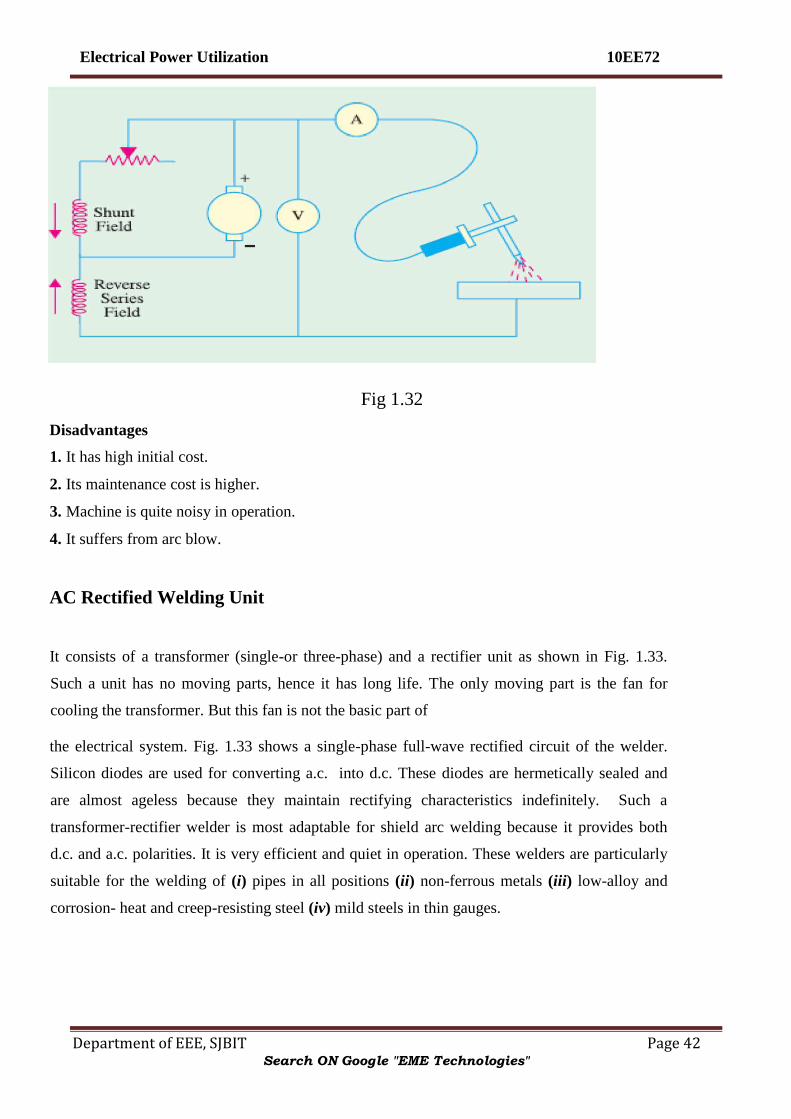
DC Welding Machines with Motor Generator Set
Such a welding plant is a self-contained single-operator motor-generator set consisting of a
reverse series winding d.c. generator driven by either a d.c. or an a.c. motor (usually 3-phase).
The series winding produces a magnetic field which opposes that of the shunt winding. On
open-circuit, only shunt field is operative and provides maximum voltage for striking the arc.
After the arc has been established, current flows through the series winding and sets up a flux
which opposes the flux produced by shunt winding. Due to decreases in the net flux, generator
voltage is decreased (Art. 1.33). With the help of shunt regulator, generator voltage and current
values can be adjusted to the desired level. Matters are so arranged that despite changes in arc
voltage due to variations in arc length, current remains practically constant. Fig. 1.32 shows the
circuit of a d.c. motor-generator type of welding machine.
Advantages. Such a d.c. welder has the following advantages :
1. It permits portable operation.
2. It can be used with either straight or reverse polarity.
3. It can be employed on nearly all ferrous and non-ferrous materials.
4. It can use a large variety of stick electrodes.
5. It can be used for all positions of welding.
Search ON Google "EME Technologies"
Electrical Power Utilization 10EE72
Department of EEE, SJBIT Page 42
Fig 1.32
Disadvantages
1. It has high initial cost.
2. Its maintenance cost is higher.
3. Machine is quite noisy in operation.
4. It suffers from arc blow.
AC Rectified Welding Unit
It consists of a transformer (single-or three-phase) and a rectifier unit as shown in Fig. 1.33.
Such a unit has no moving parts, hence it has long life. The only moving part is the fan for
cooling the transformer. But this fan is not the basic part of
the electrical system. Fig. 1.33 shows a single-phase full-wave rectified circuit of the welder.
Silicon diodes are used for converting a.c. into d.c. These diodes are hermetically sealed and
are almost ageless because they maintain rectifying characteristics indefinitely. Such a
transformer-rectifier welder is most adaptable for shield arc welding because it provides both
d.c. and a.c. polarities. It is very efficient and quiet in operation. These welders are particularly
suitable for the welding of (i) pipes in all positions (ii) non-ferrous metals (iii) low-alloy and
corrosion- heat and creep-resisting steel (iv) mild steels in thin gauges.
Search ON Google "EME Technologies"

Electrical Power Utilization 10EE72
Department of EEE, SJBIT Page 43
Fig 1.33
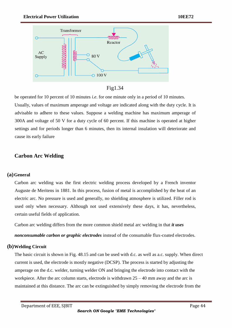
AC Welding Machines
As shown in Fig. 1.34, it consists of a step-down transformer with a tapped secondary having an
adjustable reactor in series with it for obtaining drooping V/I characteristics. The secondary is
tapped to give different voltage/ current settings.
Advantages.This a.c. welder which can be operated from either a single-phase or 3-phase
supply has the following advantages : (i) Low initial cost (ii) Low operation and maintenance
cost (iii) Low wear (iv) No arc blow
Disadvantages. (i) its polarity cannot be changed (ii) it is not suitable for welding of cast iron and non-
ferrous metals.
Duty Cycle of a Welder
The duty cycle of an arc welder is based on a working period of 10 minutes. For example,if a
welder is operated for 2 minutes in a period of 10 minutes, then its percentage duty cycle is
(2/10) × 100 = 20 percent. Conversely, a 10 percent duty cycle would mean that the welder
would
Search ON Google "EME Technologies"
Electrical Power Utilization 10EE72
Department of EEE, SJBIT Page 44
Fig1.34
be operated for 10 percent of 10 minutes i.e. for one minute only in a period of 10 minutes.
Usually, values of maximum amperage and voltage are indicated along with the duty cycle. It is
advisable to adhere to these values. Suppose a welding machine has maximum amperage of
300A and voltage of 50 V for a duty cycle of 60 percent. If this machine is operated at higher
settings and for periods longer than 6 minutes, then its internal insulation will deteriorate and
cause its early failure
Carbon Arc Welding
(a) General
Carbon arc welding was the first electric welding process developed by a French inventor
Auguste de Meritens in 1881. In this process, fusion of metal is accomplished by the heat of an
electric arc. No pressure is used and generally, no shielding atmosphere is utilized. Filler rod is
used only when necessary. Although not used extensively these days, it has, nevertheless,
certain useful fields of application.
Carbon arc welding differs from the more common shield metal arc welding in that it uses
nonconsumable carbon or graphic electrodes instead of the consumable flux-coated electrodes.
(b) Welding Circuit
The basic circuit is shown in Fig. 48.15 and can be used with d.c. as well as a.c. supply. When direct
current is used, the electrode is mostly negative (DCSP). The process is started by adjusting the
amperage on the d.c. welder, turning welder ON and bringing the electrode into contact with the
workpiece. After the arc column starts, electrode is withdrawn 25 – 40 mm away and the arc is
maintained at this distance. The arc can be extinguished by simply removing the electrode from the
Search ON Google "EME Technologies"

Electrical Power Utilization 10EE72
Department of EEE, SJBIT Page 45
workpiece completely. The only function of the carbon arc is to supply heat to the base metal. This heat
is used to melt the base metal or filler rod for obtaining fusion weld Depending on the type and size of
electrodes, maximum current values range from 15 A to 600 A for single-electrode carbon arc welding.
(c) Electrodes
These are made of either carbon or graphite, are usually 300 mm long and 2.5 – 12mm in
diameter. Graphite electrodes are harder, more brittle and last longer than carbon electrodes.
They can withstand higher current densities but their arc column is harder to control. Though
considered nonconsumable, they do disintegrate gradually due to vaporisation and oxidisation.
Fig1.35
(d) Applications
1. The joint designs that can be used with carbon arc welding are butt joints, bevel joints,
flange joints, lap joints and fillet joints.
2. This process is easily adaptable for automation particularly where amount of weld deposit is large and
materials to be fabricated are of simple geometrical shapes such as water tanks.
3. It is suitable for welding galvanised sheets using copper-silicon-manganese alloy filler metal.
4. It is useful for welding thin high-nickel alloys.
5. Monel metal can be easily welded with this process by using a suitable coated filler rod.
6. Stainless steel of thinner gauges is often welded by the carbon-arc process with excellent results.
Search ON Google "EME Technologies"

Electrical Power Utilization 10EE72
Department of EEE, SJBIT Page 46
(e) Advantages and Disadvantages
1. The main advantage of this process is that the temperature of the molten pool can be easily controlled by
simply varying the arc length.
2. It is easily adaptable to automation.
3. It can be easily adapted to inert gas shielding of the weld and
4. It can be used as an excellent heat source for brazing, braze welding and soldering etc.
Its disadvantages are as under:
1. A separate filler rod has to be used if any filler material is required.
2. Since arc serves only as a heat source, it does not transfer any metal to help reinforce the weld
joint.
3. The major disadvantage of the carbon-arc process is that blow holes occur due to magnetic arc
blow especially when welding near edges of the workpiece.
Submerged Arc Welding
In this fusion process, welding is done under a blanket of granulated flux which shields the weld
from all bad effects of atmospheric gases while a consumable electrode is continuously and
mechanically fed into the arc. The arc, the end of the bare metal electrode and the molten weld
pool are all submerged under a thick mound of finely-divided granulated powder that contains
deoxidisers, cleansers and other fluxing agents. The fluxing powder is fed from a hopper that is
carried on the welding head itself (Fig. 1.36). This hopper spread the powder in a continuous
mound ahead of the
Search ON Google "EME Technologies"

Electrical Power Utilization 10EE72
Department of EEE, SJBIT Page 47
Fig 1.36
electrode in the direction of welding. Since arc column is completely submerged under the
powder, there is no splatter or smoke and, at the same time, weld is completely protected from
atmospheric contamination. Because of this protection, weld beads are extremely smooth. The
flux adjacent to the arc column melts and floats to the top of the molten pool where it solidifies
to form slag. This slag is easy to remove. Often it cracks off by itself as it cools. The unused
flux is removed and is reused again and again.
The electrode is either a bare wire or has a slight mist of copper coated over it to prevent
oxidation. In automatic or semi-automatic submerged arc welding, wire electrode is fed
mechanically through an electrically contacting collet. Though a.c. power supply may be used,
yet d.c. supply is more popular because it assures a simplified and positive control of the
welding process.
This process requires high current densities about 5 to 6 times of those used in ordinary manual
stick electrode welding. As a result, melting rate of the electrode as well as welding speed
become much higher. Faster welding speed minimizes distortion and warpage. The submerged
arc process is suitable for
1. Welding low-alloy, high-tensile steels.
2. Welding mild, low-carbon steels.
3. Joining medium-carbon steel, heat-resistant steels and corrosion-resistant steels etc.
4. Welding nickel, Monel and other non-ferrous metals like copper.
This process has many industrial applications such as fabrication of pipes, boiler pressure
vessels, railroad tank cars, structural shapes etc. which demand welding in a straight line. Welds
Search ON Google "EME Technologies"

Electrical Power Utilization 10EE72
Department of EEE, SJBIT Page 48
made by this process have high strength and ductility. A major advantage of this process is that
fairly thick sections can be welded in a single pass without edge preparation.
Submerged arc welding can be done manually where automatic process is not possible such as
on curved lines and irregular joints. Such a welding gun is shown in Fig. 1.37. Both manual and
automatic submerged arc processes are most suited for flat and slightly downhill welding
positions.
Fig 1.37
Twin Submerged Arc Welding
As shown in Fig. 1.38 in this case, two electrodes are used simultaneously instead of one.
Hence, weld deposit size is increased considerably. Moreover, due to increase in welding
current (upto 1500 A), much deeper penetration of base metal is achieved.
Search ON Google "EME Technologies"

Electrical Power Utilization 10EE72
Department of EEE, SJBIT Page 49
Fig1.38
Gas Shield Arc Welding
In this fusion process, welding is done with bare electrodes but weld zone is shielded from the
atmosphere by a gas which is piped to the arc column. Shielding gases used are carbon dioxide,
argon, helium, hydrogen and oxygen. No flux is required. Different processes using shielding
gas are as follows.
(a) Tungsten inert-gas (TIG) Process
In this process, non-consumable tungsten electrode is used and filler wire is fed separately. The
weld zone is shielded from the atmosphere by the inert gas (argon or helium) which is ducted
directly to the weld zone where it surrounds the tungsten and the arc column.
(b) Metal inert-gas (MIG) Process
It is a refinement of the TIG process. It uses a bare consumable (i.e. fusible) wire electrode
which acts as the source for the arc column as well as the supply for the filler material. The weld
zone is shielded by argon gas which is ducted directly to the electrode point.
TIG Welding
(a) Basic Principle
It is an electric process which uses a bare non-consumable tungsten electrode for striking the arc
only (Fig. 48.19). Filler material is added separately. It uses an inert gas to shield the weld
Search ON Google "EME Technologies"

Electrical Power Utilization 10EE72
Department of EEE, SJBIT Page 50
puddle from atmospheric contamination. This gas is ducted directly to the weld zone from a gas
cylinder.
(b) Welding Equipment
The usual TIG welding system consists of the following (Fig. 48.20).
1. A standard shield arc welding machine complete with cables etc.
2. A supply of inert gas complete with hose, regulators etc.
3. A source of water supply (in the case of water-cooled torches).
4. A TIG torch with a control switch to which all the above are connected.
(c) Electrodes
The electrodes are made of either pure tungsten or zirconiated or thoriated tungsten.
Addition of zironium or thorium (0.001 to 2%) improves electron emission tremendously.
Fig 1.39
(d) Power Supply
The three basic power supplies used in TIG operation are :
1. DCSP power supply–here electrode is negative, runs cooler and, hence, can be thin.
2. DCRP power supply–here electrode is positive and hot. Hence, it has to be large.
3. A.C. high frequency (ACHF) power supply–it is a combination of standard a.c. supply of 50 Hz and
high-voltage high-frequency d.c. supply. The function of this d.c. supply is to sustain the arc when a.c.
supply
is at zero current positions.
(e) Advantages of TIG Welding
1. It provides maximum protection to weld bead from atmospheric contamination.
Search ON Google "EME Technologies"

Electrical Power Utilization 10EE72
Department of EEE, SJBIT Page 51
2. TIG welds are stronger, more ductile and more corrosion-resistant than those of shield metal arc
welding.
3. Since no flux is used, there is no flux entrapment in the bead.
4. Since no flux is required, a wider variety of joint designs can be used.
5. No post-weld cleansing is necessary.
6. There is no weld splatter or sparks that could damage the surface of the base metal.
7. It gives relatively fast welding speeds.
8. It is suitable for welding food or medical containers where entrapment of any decaying organic
matter could be extremely harmful.
9. It is suitable for all welding positions–the flat, horizontal, vertical and overhead positions.
The joints suitable for TIG welding process are (i) butt joint (ii) lap joint (iii) T-joint,
(iv) corner joint and (v) edge joint.
(f) Applications
1. Aluminum and its alloys — AC/DCRP
2. Magnesium and its alloys — ACHF
3. Stainless steel — DCSP
4. Mild steel, low-alloy steel, medium — DCSP -carbon steel and cast iron — DCSP
5. Copper and allows — DCSP
6. Nickel and alloys — DCSP
TIG welding is also used for dissimilar metals, hard facing and surfacing of metals. Special
industrial applications include manufacture of metal furniture and air-conditioning equipment.
Fig. 1.40 shows Phillips 400-D compact fan-cooled DC TIG welding set which has an open-
circuit voltage of 80 V and a welding current of 400 A with 60% duty cycle and 310 A with
100% duty cycle.
MIG Welding
Search ON Google "EME Technologies"

Electrical Power Utilization 10EE72
Department of EEE, SJBIT Page 52
(a) Basic Principle
It is also called inert-gas consumable- electrode process. The fusible wire electrode is driven by
the drive wheels. Its function is two-fold: to produce arc column and to provide filler material.
This process uses inert gas for shielding the weld zone from atmospheric contamination. Argon
is used to weld non-ferrous metals though helium gives better control of porosity and arc
stability. This
Fig 1.40 process can deposit large quantities of weld metal at a fast welding speed. The process is easily
adaptable to semi-automatic or fully automatic operations.
(b) Welding Equipment
The basic MIG welding system (Fig. 1.43) consists of the following :
1. Welding power supply
2. Inert gas supply with a regulator and flow meter
3. Wire feed unit containing controls for wire feed, gas flow and the ON/OFF switch for MIG torch 4.
MIG torch
5. Depending on amperage, a water cooling unit.
Search ON Google "EME Technologies"

Electrical Power Utilization 10EE72
Department of EEE, SJBIT Page 53
Fig 1.42
(c) Electrode
It is a bare wire fed to the MIG gun by a suitable wire-feed mechanism.
(d) Power Supply
The major power supply used for MIG welding is DCRP and the machines which provide this
supply are motor-generator sets or a.c. transformers with rectifiers (Art. 1.44). They have either
CAV or RAV characteristics (Art. 1.42). The CAV supply gives the operator great latitude in
arc length and is helpful in preventing the wire electrode from stubbing. A DCRP current
produces deeper penetration and a cleaner weld surface than other types of current. The RAV
machines are more suitable for automatic operation. They are capable of handling large
diameter wires than CAV machines. Fig. 1.44 shows semi-automatic forced-air cooled arc
welding set MIG-400. It consists of (i) Indarc 400 MMR rectifier which is basically a 3-phase
transformer rectifier with silicon
Search ON Google "EME Technologies"

Electrical Power Utilization 10EE72
Department of EEE, SJBIT Page 54
diodes and a constant potential output. It provides maximum current of 400 A at 40 V for 75% duty
cycle and 350 A at 42 V for 100% duty cycle.
(ii) Indarc Wire Feeder which has a twin roll drive system, designed to feed 0.8 to 2.4 mm diameter
welding wires to a hand-operated MIG welding torch.
(iii) MIG Torches which are available in both air-cooled and water-cooled varieties. Fig. 1.45(a) and (b)
show light-weight swan-necked torches which are designed to operate upto 360 A and 400 A with
CO2 as shielding gas. Fig. 48.25 (c) shows a heavy-duty water-cooled torch designed to operate
upto 550 A with CO2 /mixed shielding gases at 100%duty cycle.
(iv) CO2 Kit for hard wire applications and Argon Kit for soft wire applications.
(e) Advantages of MIG Welding
1. Gives high metal deposit rates varying from 2 to 8 kg/h.
2. Requires no flux.
3. Requires no post-welding cleaning.
4. Gives complete protection to weld bead from atmospheric contamination.
5. Is adaptable for manual and automatic operations.
6. Can be used for a wide range of metals both ferrous and non-ferrous.
7. Is easy to operate requiring comparatively much less operating skill.
8. Is especially suited for horizontal, vertical and overhead welding positions.
(f) Applications
Search ON Google "EME Technologies"

Electrical Power Utilization 10EE72
Department of EEE, SJBIT Page 55
With inert gas shielding, this process is suitable for fusion welding of (i) aluminium and its
alloys (ii) nickel and its alloys (iii) copper alloys (iv) carbon steels (v) low-alloy steels (vi) high
strength steels and (vii) titanium.
.
Atomic Hydrogen Welding
(a) General
It is a non-pressure fusion welding process and the welder set is used only as heat supply for the
base metal. If additional metal is required, a filler rod can be melted into the joint. It uses two
tungsten electrodes between which an arc column (actually, an arc fan) is maintained by an a.c.
supply.
(b) Basic Principle
As shown in Fig. 1.46, an arc column is struck between two tungsten electrodes with an a.c.
power supply. Soon after, normal molecular hydrogen (H2) is forced through this arc column.
Due to intense heat of the arc column, this diatomic hydrogen is dissociated into atomic
hydrogen (H).
Fig1.45
However, atomic hydrogen being unstable, recombines to form stable molecular hydrogen. In so
doing, it releases intense heat at about 3750°C which is used to fuse the metals.
(c) Welding Equipment
Search ON Google "EME Technologies"

Electrical Power Utilization 10EE72
Department of EEE, SJBIT Page 56
The welding equipment essentially consists of the following :
1. Standard welding machine consisting of a step-down transformer with tapped secondary (not shown in
Fig. 48.27) energised from normal a.c. supply. Amperage requirement ranges from 15 A to 150 A
2. Hydrogen gas supply with an appropriate regulator
3. Atomic hydrogen welding torch having an ON-OFF switch and a trigger for moving the two tungsten
electrodes close together for striking and maintaining the arc column
Fig 1.46
(d) Method of Welding
The torch is held in the right hand with first finger resting lightly on the trigger.
The arc is struck either by allowing the two tungsten electrodes to touch and
separate or by drawing the separated electrodes over a carbon block. At the same
time, a stream of hydrogen is allowed to flow through the arc. As soon as the arc
strikes, an intensely hot flame extends fanwise between the electrodes.
When this fan touches the workpiece, it melts it down quickly. If filler material is required,
it can be added from the rod held in the left hand as in gas welding.
(e) Advantages
Search ON Google "EME Technologies"

Electrical Power Utilization 10EE72
Department of EEE, SJBIT Page 57
1. Arc and weld zone are shrouded by burning hydrogen which, being an active reducing agent, protects
them from atmospheric contamination.
2. Can be used for materials too thin for gas welding.
3. Can weld quite thick sections.
4. Gives strong, ductile and sound welds.
5. Can be used for welding of mild steel, alloy steels and stainless steels and aluminum alloys.
6. Can also be used for welding of most non-ferrous metals such as nickel, monel, brass, bronze, tungsten
and molybdenum etc.
Resistance Welding
It is fundamentally a heat and squeeze process. The term ‘resistance welding’ denotes a group
of processes in which welding heat is produced by the resistance offered to the passage of
electric current through the two metal pieces being welded. These processes differ from the
fusion processes in the sense that no extra metal is added to the joint by means of a filler wire or
electrode. According to Joule‘s law, heat produced electrically is given by H = I2Rt/J.
Obviously, amount of heat produced depends on.
(i) square of the current (ii) the time of current and (iii) the resistance offered.
As seen, in simple resistance welding, high-amperage current is necessary for adequate weld.
Usually, R is the contact resistance between the two metals being welded together. The current
iscpassed for a suitable length of time controlled by a timer. The various types of resistance
welding processes may be divided into the following four main groups : (i) spot welding (ii)
seam welding
(iii) projection welding and (iv) butt welding which could be further
subdivided into flash welding, upset welding and stud welding etc.
Advantages
Some of the advantages of resistance welding are as under :
1. Heat is localized where required 2. Welding action is rapid
3. No filler material is needed 4. Requires comparatively lesser skill
5. Is suitable for large quantity production
6. Both similar and dissimilar metals can be welded
Search ON Google "EME Technologies"

Electrical Power Utilization 10EE72
Department of EEE, SJBIT Page 58
7. Parent metal is not harmed 8. Difficult shapes and sections can be welded.
Only disadvantages are with regard to high initial as well as maintenance cost.
It is a form of resistance welding in which the two surfaces are joined by spots of fused metal
caused by fused metal between suitable electrodes under pressure.
Spot Welding
The process depends on two factors :
1. Resistance heating of small portions of the two workpieces to plastic state and
2. Application of forging pressure for welding the two workpieces.
Heat produced is H = I2
Rt/J. The resistance R is made up of (i) resistance of the electrodes and
metals themselves (ii) contact resistance between electrodes and workpieces and (iii) contact
resistance between the two workpieces. Generally, contact resistance between the two
workpieces is the greatest.
As shown in 1.48 (b), mechanical pressure is applied by the tips of the two electrodes. In fact,
these electrodes not only provide the forging pressure but also carry the welding current and
concentrate the welding heat on the weld spot directly below them. Fig. 1.48(a) shows
diagrammatically the basic parts of a modern spot welding. It consists of a step-down
transformer which can supply huge currents (upto 5,000 A) for short duration of time.
Search ON Google "EME Technologies"

Electrical Power Utilization 10EE72
Department of EEE, SJBIT Page 59
The lower arm is fixed whereas the upper one is movable. The electrodes are made of low-
resistance, hard-copper alloy and are either air cooled or butt-cooled by water circulating
through the rifled drillings in the electrode. Pointed electrodes [Fig. 48.29 (a)] are used for
ferrous materials
Fig: 1.48
Search ON Google "EME Technologies"

Electrical Power Utilization 10EE72
Department of EEE, SJBIT Page 60
whereas domed electrodes [Fig. 48.25 (b)] are used for non-ferrous materials. Flat domes are used
when spot-welding deformation is not desired. The weld size is determined by the diameter of the
electrode.
The welding machine is cycled in order to produce the required heat timed to coincide with the
pressure exerted by the electrodes as shown in Fig. 48.28 (a). As the movable electrode comes
down and presses the two work pieces A and B together, current is passed through the assembly.
The metals under the pressure zone get heated upto about 950°C and fuse together. As they fuse,
their resistance is reduced to zero, hence there is a surge of current. This surge is made to switch
off the welding current automatically. In motor-driven machines, speeds of 300 strokes minute
are common. Spot welders are of two different types. One is a stationary welder which is
available in different sizes. The other has a stationary transformer but the electrodes are in a gun
form.
Fig1.49
Electric resistance spot welding is probably the best known
and most widely-used because of its low cost, speed and dependability. It can be easily
performed by even a semi-skilled operator. This process has a fast welding rate and quick set-up
time apart from having low unit cost per weld.
Spot welding is used for galvanized, tinned and leadcoated sheets and mild steel sheet work. This
technique is also applied to non-ferrous materials such as brass, aluminium, nickel and bronze etc.
Search ON Google "EME Technologies"

Electrical Power Utilization 10EE72
Department of EEE, SJBIT Page 61
Seam Welding
The seam welder differs from ordinary spot welder only in respect of its electrodes which are of
disc or roller shape as shown in Fig. 1.50 (a). These copper wheels are power driven and rotate
whilst gripping the work. The current is so applied through the wheels that the weld spots either
overlap as in Fig. 48.30 (b) or are made at regular intervals as in Fig. 1.50 (c). The continuous or
overlapped seam weld is also called stitch weld whereas the other is called roll weld.
Seam welding is confined to welding of thin materials ranging in thickness from 2 mm to 5 mm.
It is also restricted to metals having low hardenability rating such as hot-rolled grades of low
alloy steels. Stitch welding is commonly used for long water-tight and gas-tight joints. Roll
welding is used for simple joints which are not water-tight or gas-tight. Seam welds are usually
tested by pillow test.
Projection Welding
It can be regarded as a mass-production form of spot welding. Technically, it is a cross between
spot welding and butt welding. It uses the same equipment as spot welding. However, in this
process, large-diameter flat electrodes (also called platens) are used. This welding process
derives its name from the fact that, prior to welding, projections are raised on the surfaces to be
welded [Fig. 1.51(a)]. As seen, the upper and lower platens are connected across the secondary
of a step-down transformer and are large enough to cover all the projections to be welded at one
stroke of the machine. When platen
A touches the workpiece, welding current flows through each projection.
The welding process is started by first lowering the upper platen A on to the work-piece and
then applying mechanical pressure to ensure correctly-forged welds. Soon after, welding current
Search ON Google "EME Technologies"

Electrical Power Utilization 10EE72
Department of EEE, SJBIT Page 62
is switched on as in spot welding. As projection areas heat up, they collapse and union takes
place at all projections simultaneously [Fig. 48.31 (b)].
It is seen that projections serve many purposes:
1. They increase the welding resistance of the material locally.
2. They accurately locate the positions of the welds.
3. They speed up the welding process by making it possible to perform several small welds
simultaneously.
4. They reduce the amount of current and pressure needed to form a good bond between two surfaces.
5. They prolong the life of the electrode considerably because the metal itself controls the heat produced.
Projection welding is used extensively by auto manufactures for joining nuts, bolts and studs to
steel plates in car bodies. This process is especially suitable for metals like brass, aluminium
and copper etc. mainly due to their high thermal conductivity.
A variation of projection welding is the metal fibre welding which uses a metal fibre rather than
a projection point (Fig. 1.52). This metal fibre is generally a felt material. Instead of projections,
tiny elements of this felt material are placed between the two metals which are then projection-
welded in the usual way
Fig1.51
Search ON Google "EME Technologies"

Electrical Power Utilization 10EE72
Department of EEE, SJBIT Page 63
Fig 1.52
Butt Welding
In this case, the two workpieces are brought into contact end-to-end and the butted ends are
heated by passing a heavy current through the joint. As in other forms of resistance welding, the
weld heat is produced mainly by the electrical resistance of the joint faces. In this case,
however, the electrodes are in the form of powerful vice clamps which hold the work-pieces and
also convey the forging pressure to the joint [Fig. 1.53].
This process is useful where parts have to be joined end-to-end or edge-to-edge. i.e. for welding pipes,
wires and rods. It is also employed for making continuous lengths of chain.
Fig 1.53
Search ON Google "EME Technologies"

Electrical Power Utilization 10EE72
Department of EEE, SJBIT Page 64
Flash Butt Welding
It is also called by the simple name of flash welding. It is similar to butt welding but with the
difference that here current is applied when ends of the two metal pieces are quite close to each
other but do not touch intimately. Hence, an arc or flash is set up between them which supplies
the necessary welding heat. As seen, in the process heat is applied before the two parts are
pressed together.
As shown in Fig. 1.54 (a), the workpieces to be welded are clamped into specially designed
electrodes one of which is fixed whereas the other is movable. After the flash has melted their
faces, current is cut off and the movable platen applies the forging pressure to form a fusion
weld. As shown in Fig. 1.54 (b), there is increase in the size of the weld zone because of the
pressure which forces the soft ends together
Fig 1.54
Upset Welding
In this process, no flash is allowed to occur between the two pieces of the metals to be welded.
When the two base metals are brought together to a single interface, heavy current is passed
between them which heats them up. After their temperature reaches a value of about 950°C, the
two pieces of base metal are pressed together more firmly. This pressing together is called
upsetting. This upsetting takes place while current is flowing and continues even after current
is switched off. This upsetting action mixes the two metals homogeneously while pushing out
many atmospheric impurities.
Search ON Google "EME Technologies"

Electrical Power Utilization 10EE72
Department of EEE, SJBIT Page 65
Stud Welding
(a) Basic Principle
It is similar to flash welding because it incorporates a method of drawing an arc between the
stud (a rod) and the surface of the base metal. Then, the two molten surfaces are brought
together under pressure to form a weld. Stud welding eliminates the need for drilling holes in
the main structure.
(b) Welding Equipment The stud welding equipment consists of a stud welding gun, a d.c. power supply capable of
giving currents upto 400 A, a device to control current and studs and ferrules which are used not
only as arc shields but also as containing walls for the molten metal.
(c) Applications
It is a low-cost method of fastening extensions (studs) to a metal surface. Most of the ferrous
and non-ferrous metals can be stud-welded successfully. Ferrous metals include stainless steel,
carbon steel and low-alloy steel. Non-ferrous metals include aluminum, lead-free brass, bronze
and chrome plated metals.
Stud welding finds application in the installations of conduit pipe hangers, planking and corrugated
roofings.
This process is also used extensively in shipbuilding, railroad and automotive industries.
Plasma Arc Welding
(a) Basic Principle
It consists of a high-current electronic arc which is forced through a small hole in a water-coled
metallic nozzle [Fig. 1.55 (a)]. The plasma gas itself is used to protect the nozzle from the
extreme heat of the arc. The plasma arc is shielded by inert gases like argon and helium which
are pumped through an extra passageway within the nozzle of the plasma torch. As seen, plasma
arc consists of electronic arc, plasma gas and gases used to shield the jet column. The idea of
using the nozzle is to constrict
Search ON Google "EME Technologies"

Electrical Power Utilization 10EE72
Department of EEE, SJBIT Page 66
Fig 1.55 the arc thereby increasing its pressure. Collision of high-energy electrons with gas molecules
produces the plasma which is swept through the nozzle and forms the current path between the
electrode and the workpiece. Plasma jet torches have temperature capability of about 35,000°C.
(b) Electrodes
For stainless steel welding and most other metals, straight polarity tungsten electrodes are used.
But for aluminium welding, reverse polarity water-cooled copper electrodes are used.
(c) Power Supply
Plasma arc welding requires d.c. power supply which could be provided either by a motor-
generator set or transformer-rectifier combination. The latter is preferred because it produces
better arc stability. The d.c. supply should have an open-circuit voltage of about 70V and
drooping voltageampere characteristics. A high-frequency pilot arc circuit is employed to start
the arc [Fig. 1.55 (b)].
(d) Method of Welding
Welding with plasma arc jet is done by a process called ‗keyhole‘ method. As the plasma jet
strikes the surface of the workpiece, it burns a hole through it. As the torch progresses along the
work-piece, this hole also progresses alongwith but is filled up by the molten metal as it
movesalong. obviously, 100 percent penetration is achieved in this method of welding. Since
plasma jet melts a large surface area of the base metal, it produces a weld bead of wineglass
design as shown in Fig. 1.56. The shape of the bead can be changed by changing the tip of the
nozzle of the torch. Practically, all welding is done mechanically.
(e) Applications
Search ON Google "EME Technologies"

Electrical Power Utilization 10EE72
Department of EEE, SJBIT Page 67
1. Plasma arc welding process has many aerospace applications.
2. It is used for welding of reactive metals and thin materials.
3. It is capable of welding high-carbon steel, stainless steel, maraging steel, copper and copper alloys,
brass alloys, aluminium and titanium.
4. It is also used for metal spraying.
Fig 1.56
5. It can be modified for metal cutting purposes. It has been used for cutting aluminium, carbon steel,
stainless steel and other hard-to-cut steels. It can produce high-quality drossfree aluminium cuts 15 cm
deep.
(f) Disadvantages
1. Since it uses more electrical equipment, it has higher electrical hazards.
2. It produces ultra-violet and infra-red radiations necessitating the use of tinted lenses.
3. It produces high-pitched noise (100 dB) which makes it necessary for the operator to use ear plugs.
5. It can be modified for metal cutting purposes. It has been used for cutting aluminium, carbon
steel, stainless steel and other hard-to-cut steels. It can produce high-quality drossfree
aluminium cuts 15 cm deep.
(f) Disadvantages
1. Since it uses more electrical equipment, it has higher electrical hazards.
2. It produces ultra-violet and infra-red radiations necessitating the use of tinted lenses.
3. It produces high-pitched noise (100 dB) which makes it necessary for the operator to use ear plugs.
Electro slag Welding
Search ON Google "EME Technologies"
Electrical Power Utilization 10EE72
Department of EEE, SJBIT Page 68
(a) General
It is a metal-arc welding process and may be considered as a further development of submerged-arc
welding.
This process is used for welding joints of thick sections of ferrous metals in a single pass and
without any special joint preparation. Theoretically, there is no upper limit to the thickness of
the weld bead. It is usually a vertical uphill process.
It is called electroslag process because heat is generated by passing current through the molten slag
which floats over the top of the metal.
(b) Welding Equipment
As shown in Fig. 1.57, two water-cooled copper shoes (or dams) are placed on either side of the
joint to be welded for the purpose of confining the molten metal in the joint area. The electrode
is fed into the weld joint almost vertically from special wire guides. There is a mechanical
device which raises the shoes and wire-feed mechanism as the weld continues upwards till it is
completed.
An a.c. welding machine has 100 percent duty cycle and which can supply currents upto 1000 A if
needed.
Search ON Google "EME Technologies"

Electrical Power Utilization 10EE72
Department of EEE, SJBIT Page 69
Fig 1.57
(c) Welding Process
The electroslag process is initiated just like submerged arc process by starting an electric arc
beneath a layer of granular welding flux. When a sufficient thick layer of hot flux or molten slag
is formed, arc action stops and from then onwards, current passes from the electrode to
workpiece through the molten slag. At this point, the process becomes truly electroslag welding.
A starting plate is used in order to build up proper depth of conductive slag before molten pool
comes in contact with the work pieces.
The heat generated by the resistance to the flow of current through the molten slag is sufficient
to melt the edges of the workpiece and the filler electrode. The molten base metal and filler
metal collect at the bottom of the slag pool forming the weld pool. When weld pool solidfies,
weld bead is formed which joins the faces of the base metal as shown in Fig. 1.53 (b).
As welding is continued upwards, flux flows to the top in the form of molten slag and cleanses
the impurities from the molten metal. A mechanism raises the equipment as the weld is
completed in the uphill vertical position.
(d) Advantages
1. It needs no special joint preparation.
2. It does welding in a single pass rather than in costly multiple passes.
Search ON Google "EME Technologies"

Electrical Power Utilization 10EE72
Department of EEE, SJBIT Page 70
3. There is theoretically no maximum thickness of the plate it can weld.
4. There is also no theoretical upper limit to the thickness of the weld bead. Weld beads upto 400 mm thick
have been performed with the presenttly-available equipment.
5. This process requires less electrical power per kg of deposited metal than either the submerged arc
welding process or the shield arc process.
6. It has high deposit rate of upto 20 kg of weld metal per hour.
7. It has lower flux consumption.
8. Due to uniform heating of the weld area, distortion and residual stresses are reduced to the minimal
amounts.
However, for electroslag welding, it is necessary to have only a square butt joint or a square edge
on the plates to be welded.
(e) Applications
It is commonly used in the fabrication of large vessels and tanks. Low-carbon steels produce excellent
welding properties with this process.
Electro gas Welding
This process works on the same basic principle as the electroslag process but has certain
additional features of submerged arc welding. Unlike electroslag process, the electrogas process
uses an inert gas for shielding the weld from oxidation and there is a continuous arc (as in
submerged arc process) to heat the weld pool.
Electron Beam Welding
In this process, welding operation is performed in a vacuum chamber with the help of a sharply
focussed beam of high-velocity electrons. The electrons after being emitted from a suitable
electrode are accelerated by the high anode voltage and are then focussed into a fine beam
which is finally directed to the workpiece. Obviously, this process needs no electrodes. The
Search ON Google "EME Technologies"

Electrical Power Utilization 10EE72
Department of EEE, SJBIT Page 71
electron beam produces intense local heat which can melt not only the metal but can even boil
it. A properly-focussed electron beam can completly penetrate through the base metal thereby
creating a small hole whose walls are molten. As the beam moves along the joint, it melt the
material coming in contact with it. The molten metal flows back to the previously-melted hole
where it fuses to make a perfect weld for the entire depth of penetration.
Electron-beam welding has following Advantages:
1. It produces deep penetration with little distortion.
2. Its input power is small as compared to other electrical welding devices.
3. Electron-beam weld is much narrower than the fusion weld.
4. It is especially suitable for reactive metals which become contaminated when exposed to air because this
process is carried out in vacuum.
5. It completely eliminates the contamination of the weld zone and the weld bead because operation is
performed in a vacuum chamber.
6. It is especially suited to the welding of beryllium which is being widely used in the fabrication of
industrial and aerospace components.
7. Its high deposition rate produces welds of excellent quality with only a single pass.
8. It is the only process which can join high temperature metals such as columbium.
At present, its only serious limitations are that it is extremely expensive and is not available in portable
form. However, recently a non-vacuum electron-beam welder has been developed.
Laser Welding
It uses an extremely concentrated beam of coherent monochromatic light i.e. light of only one
colour (or wavelength). It concentrates tremendous amount of energy on a very small area of the
workpiece to produce fusion. It uses solid laser (ruby, saphire), gas laser (CO2) and
semiconductor laser. Both the gas laser and solid laser need capacitor storage to store energy for
later injection into the flash tube which produces the required laser beam.
The gas laser welding equipment consists of (i) capacitor bank for energy storage (ii) a
triggering device (iii) a flash tube that is wrapped with wire (iv) lasing material (v)
focussing lens and (vi) a worktable that can rotate in the three X, Y and Z directions.
Search ON Google "EME Technologies"

Electrical Power Utilization 10EE72
Department of EEE, SJBIT Page 72
When triggered, the capacitor bank supplies electrical energy to the flash tube through the wire.
This energy is then converted into short-duration beam of laser light which is pin-pointed on the
workpiece as shown in Fig. 48.38. Fusion takes place immediately and weld is completed fast.
Fig 1.58
Since duration of laser weld beam is very short (2 ms or so), two basic welding methods have
been adopted. In the first method, the workpiece is moved so fast that the entire joint is welded
in a single burst of the light. The other method uses a number of pulses one after the other to
form the weld joint similar to that formed in electric resistance seam welding (Art 1.51).
Laser welding is used in the aircraft and electronic industries for lighter gauge metals.
Some of the advantages of laser welding process are as follows :
1. It does not require any electrode.
2. It can make welds with high degree of precision and on materials as thin as 0.025 mm.
3. It does not heat the workpiece except at one point. In fact, heat-affected zone is virtually nonexistent.
4. Liquidus is reached only at the point of fusion.
5. It can produce glass-to-metal seals as in the construction of klystron tubes.
6. Since laser beam is small in size and quick in action, it keeps the weld zone uncontaminated.
7. It can weld dissimilar metals with widely varying physical properties.
8. It produces minimal thermal distortion and shrinkage because area of heat-affected zone is the minimum
possible.
9. It can easily bond refractory materials like molybdenum, titanium and tantalium etc.
However, the major disadvantage of this process is its slow welding speed. Moreover, it is limited to
welding with thin metals only.
Search ON Google "EME Technologies"

Electrical Power Utilization 10EE72
Department of EEE, SJBIT Page 73
Expected Questions
1. Explain the properties of good heating element?
2. Define welding, compare resistance and arc welding?
3. A 27kW, 3phase 400V reistance oven is to employ niclel-chrome strip 0.25mm thick for the three
star connected heating elements. If the temperature of the strip is to be 10000C and that of the
charge to be 6000C, estimate suitable width for the strip. Assume emissivity=0.9 and radiating
efficiency to be 0.5 and resistivity of the strip material is 101.6x10⁻⁸
-m.
4. Explain the principles of Induction heating
5. With neat sketch explain the working of a Vertical core type induction furnace.
6. Calculate the efficiency of a high frequency induction furnace which takes 10minutes to melt
1.8kg of aluminium. The inuput to the furnace is 4.8kW and initial temperature 150C.
Specific heat of aluminium=0.88kJ/kg 0C. Melting point of aluminium=660
0C. Latent heat of
fusion of aluminium=32kJ/kg. Assume 1kJ=2.78x10⁻⁴
kWh.
7. Explain clearly resitance and arc heating?
8. With neat figure, explain vertical core type induction furnace.
9. A vubic wate tank has surface area of 6m2 and is filled to 90% capacity six times daily. The water
is heated from 200C to 65
0C. The losses per square metre of tank surface per 1
0C temperature
difference is 6.3 W. Find the loading kW and the efficency of the tank. Assume specific heat of
water=4200J/kg/0C and 1kWh=3.6MJ.
10. What are the requirements of good welding.
11. Write classification of electric welding.
12. What are the advantages of resistance welding? Explain clearly Butt welding along with its
application.
13. Discuss methods of temperature control of resistance oven.
14. Discuss the following applications in dielectric heating. i) Heating of raw plastics ii) Gluing of
wood.
15. A cubic water tank has surface area of 5.4m2
and is filled to 92% capacity five times daily. The
water is heated from 150C to 60
0C. The losses per square meter of tank per 1
0C temperature
difference are 5.9 W. Calculate i) Loading in kW ii) Efficiency of tank. Assume specific heat of
water=4.186kJ/kg/0C
16. Define the term welding. What is resistance welding? What are its limitations?
17. Compare A.C and D.C welding?
18. Explain the terms i) Anodizing ii) Polarizing with respect to electrolytic process.
Search ON Google "EME Technologies"

Electrical Power Utilization 10EE72
Department of EEE, SJBIT Page 74
Unit 2
Electrolytic Process
Definition of Electrolysis
An electrolyte is such a chemical that's atoms are normally closely bonded together but when it is
dissolved in water, its molecules split up into positive and negative ions. The positively charged ions are
referred as cations whereas negatively charged ions are referred as anions. Both cations and anions move
freely in the solution.
Principle of Electrolysis
As discussed in the definition of electrolyte, whenever any electrolyte gets dissolved in water, its
molecules split into cations and anions moving freely in the electrolytic solution. Now two metal rods are
immersed in the solution and an electrical potential difference applied between the rods externally
preferably by a battery. These partly immersed rods are technically referred as electrodes. The electrode
connected with negative terminal of the battery is known as cathode and the electrode connected with
positive terminal of the battery is known as anode. The freely moving positively charged cations are
attracted by cathode and negatively charged anions are attracted by anode. In cathode, the positive cations
take electrons from negative cathode and in anode, negative anions give electrons to the positive anode.
For continually taking and giving electrons in cathode and anode respectively, there must be flow of
electrons in the external circuit of the electrolytic. That means, electric current continues to circulate
around the closed loop created by battery, electrolytic and electrodes. This is the most basic principle of
electrolysis
Fig:2.1: Electrolysis process
Search ON Google "EME Technologies"

Electrical Power Utilization 10EE72
Department of EEE, SJBIT Page 75
Electrolysis of Copper Sulfate
Whenever copper sulfate or CuSO4 is added to water, it gets dissolved in the water. As the CuSO4 is an
electrolyte, it splits into Cu+ +
(cation) and SO4 − −
(anion) ions and move freely in the solution. Now if two
copper electrodes are immersed in that solution, the Cu+ +
ions (cation) will be attracted towards cathode
i.e. the electrode connected to the negative terminal of the battery. On reaching on the cathode, each Cu+
+ ion will take electrons from it and becomes neutral copper atoms. Similarly the SO4
− − (anion) ions will
be attracted by anode i.e. the electrode connected to the positive terminal of the battery. So SO4 − −
ions
will move towards anode where they give up two electrons and become SO4 radical but since SO4 radical
can not exist in the electrical neutral state, it will attack copper anode and will form copper sulfate. If
during electrolysis of copper sulfate, we use carbon electrode instead of copper or other metal electrodes,
then electrolysis reactions will be little bit different. Actually SO4 can not react with carbon and in this
case the SO4 will react with water of the solution and will form sulfuric acid and liberate oxygen.
The process described above is known as electrolysis. In the above process, after taking electrons the
neutral copper atoms get deposited on the cathode. At the same time, SO4reacts with copper anode and
becomes CuSO4 but in water it can not exist as single molecules instead of that CuSO4 will split into Cu+ +
,
SO4 − −
and dissolve in water. So it can be concluded that, during electrolysis of copper sulfate with copper
electrodes, copper is deposited on cathode and same amount of copper is removed from anode.
Faraday's Laws of Electrolysis
Before understanding Faraday's laws of electrolysis, we have to recall the process of electrolysis of a
metal sulfate.
Whenever an electrolyte like metal sulfate is diluted in water, its molecules split into positive and negative
ions. The positive ions or metal ions move to the electrodes connected with negative terminal of the battery
where these positive ions take electrons from it, become pure metal atom and get deposited on the
electrode. Whereas negative ions or sulphions move to the electrode connected with positive terminal of
the battery where these negative ions give up their extra electrons and become SO4 radical. Since
SO4 cannot exist in electrically neutral state, it will attack metallic positive electrode and form metallic
sulfate which will again dissolve in the water. Faraday’s laws of electrolysis combine two laws and these
are,
Search ON Google "EME Technologies"

Electrical Power Utilization 10EE72
Department of EEE, SJBIT Page 76
Faraday's First Law of Electrolysis
From the brief explanation above, it is clear that the flow of current through the external battery circuit
fully depends upon how many electrons get transferred from negative electrode or cathode to
positivemetallic ion or cations. If the cations have valency of two like Cu++
then for every cation, there
would be two electrons transferred from cathode to cation. We know that every electron has negative
electrical charge − 1.602 X 10 − 19
Coulombs and say it is - e. So for disposition of every Cu atom on the
cathode, there would be - 2.e charge transfers from cathode to cation. Now say for t time there would be
total n number of copper atoms deposited on the cathode, so total charge transferred, would be - 2.n.e
Coulombs. Mass m of the deposited copper is obviously function of number of atoms deposited. So, it can
be concluded that the mass of the deposited copper is directly proportional to the quantity of electrical
charge that passes through the electrolyte. Hence mass of deposited copper m ∝ Q quantity of electrical
charge passes through the electrolyte.
Faraday's First Law of Electrolysis states that only,
According to this law, the chemical deposition due to flow of electric current through an electrolyte is
directly proportional to the quantity of electricity (coulombs) passed through it.
i.e. mass of chemical deposition,
Where Z is a constant of proportionality and is known as electrochemical equivalent of the substance.
If we put Q = 1 coulombs in the above equation, we will get Z = m which implies that electrochemical
equivalent of any substance is the amount of the substance deposited on passing of 1 coulomb through its
solution. This constant of passing of electrochemical equivalent is generally expressed in terms of
milligram per coulomb or kilogram per coulomb.
Faraday's Second Law of Electrolysis
So far we have learned that the mass of the chemical, deposited due to electrolysis is proportional to the
quantity of electricity that passes through the electrolyte. The mass of the chemical, deposited due to
electrolysis is not only proportional to the quantity of electricity passes through the electrolyte, but it also
depends upon some other factor. Every substance will have its own atomic weight. So for same number of
atoms, different substances will have different masses. Again, how many atoms deposited on the electrodes
also depends upon their number of valency. If valency is more, then for same amount of electricity, number
Search ON Google "EME Technologies"

Electrical Power Utilization 10EE72
Department of EEE, SJBIT Page 77
of deposited atoms will be less whereas if valency is less, then for same quantity of electricity, more
number of atoms to be deposited. So, for same quantity of electricity or charge passes through different
electrolytes, the mass of deposited chemical is directly proportional to its atomic weight and inversely
proportional to its valency.
Faraday's second law of electrolysis states that, when the same quantity of electricity is passed through
several electrolytes, the mass of the substances deposited are proportional to their respective chemical
equivalent or equivalent weight.
Applications of Electrolysis:
Electrolytic Refining of Metals
The process of electrolytic refining of metals is used to extract impurities from crude metals. Here in this
process, a block of crude metal is used as anode, a diluted salt of that metal is used as electrolyte and plates
of that pure metal is used as cathode.
Electrolytic Refining of Copper
For understanding the process of electrolytic refining of metals, we will discuss about an example
of electrolytic refining of copper. Copper extracted from its ore, known as blister copper, is 98 to 99 %
pure but it can easily be made up to 99.95% pure for electrical application by the process
of electrorefining.
In this process of electrolysis, we use a block of impure copper as anode or positive electrode, copper
sulfate acidified with sulfuric acid, electrolyte and pure copper plates coated with graphite, as cathode or
negative electrode.
The copper sulfate splits into positive copper ion (Cu+ +
) and negative sulfate ion (SO4 − −
). The positive
copper ion (Cu+ +
) or cations will move towards negative electrode made of pure copper where it takes
electrons from cathode, becomes Cu atom and is deposited on the graphite surface of the cathode.
Search ON Google "EME Technologies"
Electrical Power Utilization 10EE72
Department of EEE, SJBIT Page 78
On the other hand, the SO4 − −
will move towards positive electrode or anode where it will receive electrons
from anode and become radical SO4 but as radical SO4 can not exist alone, it will attack copper of anode
and form CuSO4. This CuSO4 will then dissolve and split in the solution as positive copper ion (Cu+ +
) and
negative sulfate ion (SO4 − −
). These positive copper ions (Cu+ +
) will then move towards negative electrode
where it takes electrons from cathode, become Cu atoms and are deposited on the graphite surface of the
cathode. In this way, the copper of impure crude will be transferred and deposited on the graphite surface
of the cathode. The metallic impurities of anode are also merged with SO4, form metallic sulfate and
dissolve in the electrolyte solution. The impurities like silver and gold, which are not effected by sulfuric
acid-copper sulfate solution, will settle down as the anode sludge or mud. At a regular interval of
electrolytic refining of copper, the deposited copper is stripped out from the cathode and anode is replaced
by a new block of crude copper.
Electroplating
The process of electroplating is theoretically same as electrorefining - only difference is that, in place of
graphite coated cathode we have to place an object on which the electroplatinghas to be done. Let's take
an example of brass key which is to be copper-platted by usingcopper electroplating.
Copper Electroplating
We have already stated that copper sulfate splits into positive copper ion (Cu+ +
) and negative sulfate ion
(SO4 − −
) in its solution. For copper electroplating, we use copper sulfate solution as electrolyte, pure
copper as anode and an object (a brass key) as cathode. The pure copper rod is connected with positive
terminal and the brass key is connected with negative terminal of a battery. While these copper rod and key
are immersed into copper-sulfate solution, the copper rod will behave as anode and the key will behave as
cathode. As the cathode or the brass key is connected with negative terminal of battery, it will attract the
positive cations or Cu+ +
ions and on reaching of Cu+ +
ions on the surface of the brass key, they will
receive electrons from it, become neutral copper atom and are about to be deposited on the surface of the
brass key as uniform layer. The sulfate or SO4 − −
ions move to the anode and extract copper from it into the
solution as mentioned in the process of electro-refining. For proper and uniform copper plating, the object
(here it is brass key) is being rotated slowly into the solution.
Search ON Google "EME Technologies"

Electrical Power Utilization 10EE72
Department of EEE, SJBIT Page 79
Electroforming
Reproduction of objects by electro-deposition on some sort of mould is known aselectroforming. This is
another very useful example among many applications of electrolysis. For that, first we have to take the
impression of objects on wax or on other wax like material. The surface of the wax mold which bears exact
impression of the object, is coated with graphite powder in order to make it conducting. Then the mold is
dipped into the electrolyte solution as cathode. During electrolysis process, the electrolyte metal will be
deposited on the graphite coated impressed surface of the mold. After obtaining a layer of desired
thickness, the article is removed and the wax is melted to get the reproduced object in form of metal shell.
A popular use of electroforming is reproduction of gramophone record dices. The original recording is
done on a record of wax composition. This wax mold is then coated with gold powder to make it
conducting. Then this mold is dipped into a blue vitriol electrolyte as cathode. The solution is kept
saturated by using a copper anode. The copper electroforming on the wax mold produces master plate
which is used to stamp a large number of shellac discs.
Factors affecting Electro deposition Process
Electrophoretic deposition (EPD), is a term for a broad range of industrial processes which
includeselectrocoating, e-coating, cathodic electrodeposition, anodic electrodeposition,
and electrophoretic coating, or electrophoretic painting. A characteristic feature of this process is
that colloidal particles suspended in a liquid medium migrate under the influence of an electric
field (electrophoresis) and are deposited onto an electrode. All colloidal particles that can be used to form
stable suspensions and that can carry a charge can be used in electrophoretic deposition. This includes
materials such as polymers, pigments, dyes, ceramics and metals.
The process is useful for applying materials to any electrically conductive surface. The materials which are
being deposited are the major determining factor in the actual processing conditions and equipment which
may be used.
Due to the wide utilization of electrophoretic painting processes in many industries, aqueous EPD is the
most common commercially used EPD process. However, non-aqueous electrophoretic deposition
applications are known. Applications of non-aqueous EPD are currently being explored for use in the
fabrication of electronic components and the production of ceramic coatings. Non-aqueous processes have
the advantage of avoiding the electrolysis of water and the oxygen evolution which accompanies
electrolysis.
Search ON Google "EME Technologies"

Electrical Power Utilization 10EE72
Department of EEE, SJBIT Page 80
Uses of EPD
This process is industrially used for applying coatings to metal fabricated products. It has been widely used
to coat automobile bodies and parts, tractors and heavy equipment, electrical switch gear, appliances,
metal furniture, beverage containers, fasteners, and many other industrial products.
EPD processes are often applied for the fabrication of supported titanium dioxide (TiO2) photocatalysts for
water purification applications, using precursor powders which can be immobilised using EPD methods
onto various support materials. Thick films produced this way allow cheaper and more rapid synthesis
relative to sol-gel thin-films, along with higher levels of photocatalyst surface area.
EPD processed have a number of advantages which have made such methods widely used
1. The process applies coatings which generally have a very uniform coating thickness without
porosity.
2. Complex fabricated objects can easily be coated, both inside cavities as well as on the outside
surfaces.
3. Relatively high speed of coating.
4. Relatively high purity.
5. Applicability to wide range of materials (metals, ceramics, polymers, etc.)
6. Easy control of the coating composition.
7. The process is normally automated and requires less human labor than other coating processes.
8. Highly efficient utilization of the coating materials result in lower costs relative to other processes.
9. The aqueous process which is commonly used has less risk of fire relative to the solvent-borne
coatings that they have replaced.
10. Modern electrophoretic paint products are significantly more environmentally friendly than many
other painting technologies.
Search ON Google "EME Technologies"

Electrical Power Utilization 10EE72
Department of EEE, SJBIT Page 81
Process of electrophoretic painting
The overall industrial process of electrophoretic deposition consists of several sub-processes:
1. The object to be coated needs to be prepared for coating. This normally consists of some kind of
cleaning process and may include the application of a conversion coating, typically an inorganic
phosphate coating.
2. The coating process itself. This normally involves submerging the part into a container or vessel
which holds the coating bath or solution and applying direct current electricity through the EPD
bath using electrodes. Typically voltages of 25 - 400 volts DC are used in electrocoating or
electrophoretic painting applications. The object to be coated is one of the electrodes, and a set of
"counter-electrodes" are used to complete the circuit.
3. After deposition, the object is normally rinsed to remove the undeposited bath. The rinsing process
may utilize an ultrafilter to dewater a portion of the bath from the coating vessel to be used as rinse
material. If an ultrafilter is used, all of the rinsed off materials can be returned to the coating vessel,
allowing for high utilization efficiency of the coating materials, as well as reducing the amount of
waste discharged into the environment.
4. A baking or curing process is normally used following the rinse. This will crosslink the polymer
and allows the coating, which will be porous due to the evolution of gas during the deposition
process, to flow out and become smooth and continuous.
Power Supply for electrolytic process
Electrolysis is a method of using a direct electric current (DC) to drive an otherwise non-spontaneous
chemical reaction. Electrolysis is commercially highly important as a stage in the separation of elements
from naturally occurring sources such as ores using an electrolytic cell. The voltage that is needed for
electrolysis to occur is called decomposition potential.
Electrolysis is the passage of a direct electric current through an ionic substance that is either molten or
dissolved in a suitable solvent, resulting in chemical reactions at the electrodes and separation of materials.
Search ON Google "EME Technologies"

Electrical Power Utilization 10EE72
Department of EEE, SJBIT Page 82
The main components required to achieve electrolysis are:
An electrolyte : a substance containing free ions which are the carriers of electric current in the electrolyte.
If the ions are not mobile, as in a solid salt then electrolysis cannot occur.
A direct current (DC) supply : provides the energy necessary to create or discharge the ions in the
electrolyte. Electric current is carried by electrons in the external circuit.
Two electrodes : an electrical conductor which provides the physical interface between the electrical
circuit providing the energy and the electrolyte
Electrodes of metal, graphite and semiconductor material are widely used. Choice of suitable electrode
depends on chemical reactivity between the electrode and electrolyte and the cost of manufacture.
Energy changes during electrolysis
The amount of electrical energy that must be added equals the change in Gibbs free energy of the reaction
plus the losses in the system. The losses can (in theory) be arbitrarily close to zero, so the maximum
thermodynamic efficiency equals the enthalpy change divided by the free energy change of the reaction. In
most cases, the electric input is larger than the enthalpy change of the reaction, so some energy is released
in the form of heat. In some cases, for instance, in the electrolysis of steam into hydrogen and oxygen at
high temperature, the opposite is true. Heat is absorbed from the surroundings, and the heating value of the
produced hydrogen is higher than the electric input.
Search ON Google "EME Technologies"

Electrical Power Utilization 10EE72
Department of EEE, SJBIT Page 83
Expected Questions
1. What do you mean by Electrolysis process?
2. Explain the extraction of metals.
3. Define electro chemical equivalent and energy efficiency.
4. State and explain faradays laws of electrolysis.
5. Explain throwing power and polarisation.
6. What do you mean by electro deposition?
7. Explain the factors affecting electro deposition.
Search ON Google "EME Technologies"

Electrical Power Utilization 10EE72
Department of EEE, SJBIT Page 84
UNIT 3 & 4
ILLUMINATION
Radiations From a Hot Body
The usual method of producing artificial light consists in raising a solid body or vapour to
incandescence by applying heat to it. It is found that as the body is gradually heated above room
temperature, it begins to radiate energy in the surrounding medium in the form of
electromagnetic waves of various wavelengths. The nature of this radiant energy depends on the
temperature of the hot body. Thus, when the temperature is low, radiated energy is in the form of
heat waves only but when a certain temperature is reached, light waves are also radiated out in
addition to heat waves and the body becomes luminous. Further increase in temperature
produces an increase in the amount of both kinds of radiations but the colour of light or visible
radiation changes from bright red to orange, to yellow and then finally, if the temperature is
high enough, to white. As temperature is increased, the wavelength of the visible radiation goes
on becoming shorter. It should be noted that heat waves are identical to light waves except that
they are of longer wavelength and hence produce no impression on the retina. Obviously, from
the point of view of light emission, heat energy represents so much wasted energy.
Radiations from a Hot Body
The usual method of producing artificial light consists in raising a solid body or vapour to
incandescence by applying heat to it. It is found that as the body is gradually heated above room
temperature, it begins to radiate energy in the surrounding medium in the form of
electromagnetic waves of various wavelengths. The nature of this radiant energy depends on
the temperature of the hot body. Thus, when the temperature is low, radiated energy is in the
form of heat waves only but when a certain temperature is reached, light waves are also radiated
out in addition to heat waves and the body becomes luminous. Further increase in temperature
produces an increase in the amount of both kinds of radiations but the colour of light or visible
radiation changes from bright red to orange, to yellow and then finally, if the temperature is
high enough, to white. As temperature is increased, the wavelength of the visible radiation goes
Search ON Google "EME Technologies"
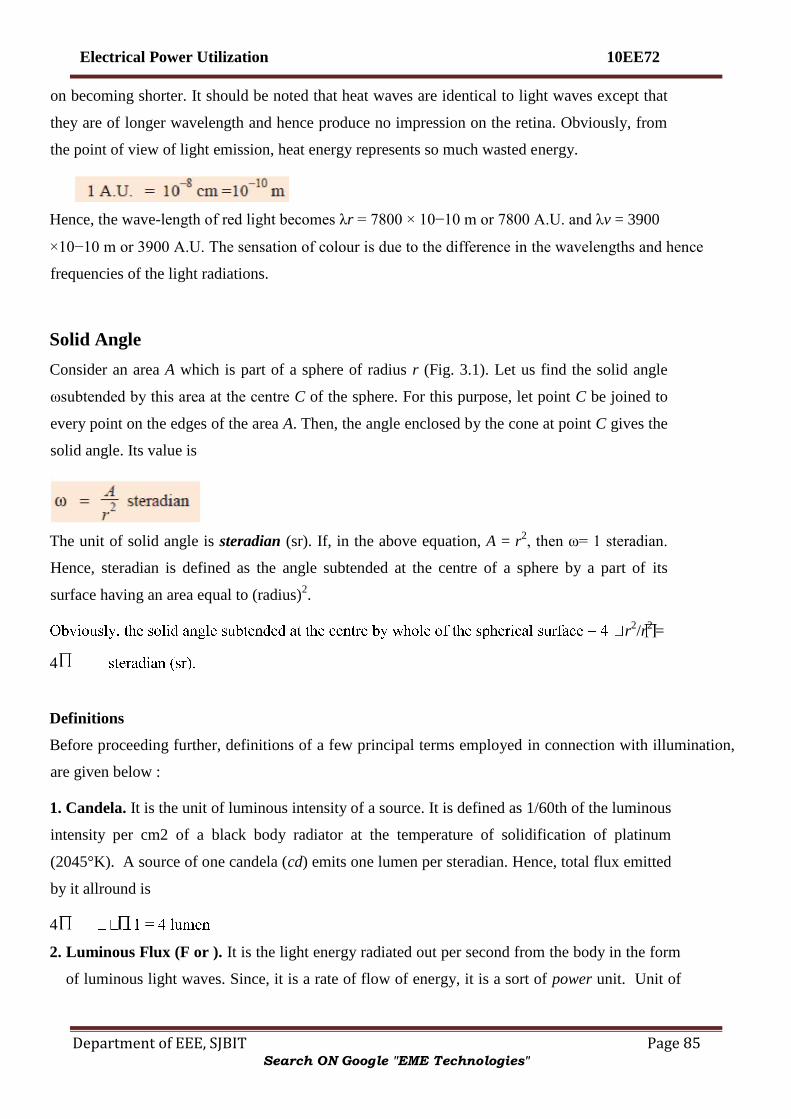
Electrical Power Utilization 10EE72
Department of EEE, SJBIT Page 85
on becoming shorter. It should be noted that heat waves are identical to light waves except that
they are of longer wavelength and hence produce no impression on the retina. Obviously, from
the point of view of light emission, heat energy represents so much wasted energy.
Hence, the wave-length of red light becomes λr = 7800 × 10−10 m or 7800 A.U. and λv = 3900
×10−10 m or 3900 A.U. The sensation of colour is due to the difference in the wavelengths and hence
frequencies of the light radiations.
Solid Angle
Consider an area A which is part of a sphere of radius r (Fig. 3.1). Let us find the solid angle
ωsubtended by this area at the centre C of the sphere. For this purpose, let point C be joined to
every point on the edges of the area A. Then, the angle enclosed by the cone at point C gives the
solid angle. Its value is
The unit of solid angle is steradian (sr). If, in the above equation, A = r2, then ω= 1 steradian.
Hence, steradian is defined as the angle subtended at the centre of a sphere by a part of its
surface having an area equal to (radius)2.
r2/r
2 =
4
Definitions
Before proceeding further, definitions of a few principal terms employed in connection with illumination,
are given below :
1. Candela. It is the unit of luminous intensity of a source. It is defined as 1/60th of the luminous
intensity per cm2 of a black body radiator at the temperature of solidification of platinum
(2045°K). A source of one candela (cd) emits one lumen per steradian. Hence, total flux emitted
by it allround is
4
2. Luminous Flux (F or ). It is the light energy radiated out per second from the body in the form
of luminous light waves. Since, it is a rate of flow of energy, it is a sort of power unit. Unit of
Search ON Google "EME Technologies"

Electrical Power Utilization 10EE72
Department of EEE, SJBIT Page 86
luminous flux is lumen (lm). It is defined as the flux contained per unit solid angle of a source
of one candela or standard candle
(Fig. 3.2). Approximate relation between lumen and electric unit of power i.e. watt is given as
3. Lumen-hour. It is the quantity of light delivered in one hour by a flux of one lumen.*
4. Luminous Intensity (I) or Candle-power of a point source in any particular direction is given
by the luminous flux radiated out per unit solid angle in that direction. In other words, it is
solid angular flux density of a source in a specified direction. If d
radiated out by a source within a solid angle of d I =
d /dω.
If flux is measured in lumens and solid angle in steradian, then its unit is lumen/steradian (lm/sr) or
candela (cd).
If a source has an average luminous intensity of I lm/sr (or I candela), then total flux radiated by it all
ωI = 4 I lumen.
Generally, the luminous intensity or candle power of a source is different in different directions.
The average candle-power of a source is the average value of its candle power in all directions.
Obviously, it is given by total flux (in lm) emitted in all directions in all planes divided by 4 .
This average candle-power is also known as mean spherical candle-power (M.S.C.P.).
If the average is taken over a hemisphere (instead of sphere), then this average candle power is known
as mean hemispherical candle-power (M.H.S.C.P.).
It is given by the total flux emitted in a hemisphere (usually the lower one) divided by the solid angle
subtended at the point source by the hemisphere.
Fig 3.2
Search ON Google "EME Technologies"
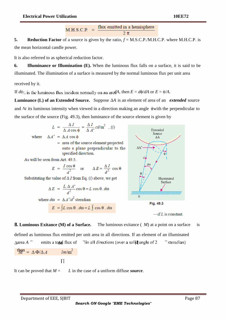
Electrical Power Utilization 10EE72
Department of EEE, SJBIT Page 87
5. Reduction Factor of a source is given by the ratio, f = M.S.C.P./M.H.C.P. where M.H.C.P. is
the mean horizontal candle power.
It is also referred to as spherical reduction factor.
6. Illuminance or Illumination (E). When the luminous flux falls on a surface, it is said to be
illuminated. The illumination of a surface is measured by the normal luminous flux per unit area
defined as luminous flux emitted per unit area in all directions. If an element of an illuminated
area A emits a total flux of
then
It can be proved that M = L in the case of a uniform diffuse source.
received by it.
If d dA , then E = d / dA or E = / A .
Luminance (L) of an Extended Source. Suppose A is an element of area of an extended source
and t its luminous intensity when viewed in a direction making an angle with the perpendicular to
the surface of the source (Fig. 49.3), then luminance of the source element is given by
8 . Luminous Exitance (M) of a Surface. The luminous exitance ( M ) at a point on a surface is
Search ON Google "EME Technologies"

Electrical Power Utilization 10EE72
Department of EEE, SJBIT Page 88
Transmittance (T) of an Illuminated Diffuse Reflecting Surface. It is defined as the ratio of the
total luminous flux transmitted by it to the total flux incident on it.
The relation between luminous exitance (M) of a surface transmitting light and illuminance (E) on
the other side of it is
Since light falling on a surface is either transmitted, reflected or absorbed the following relation holds
good
reflected from a small area of the surface to t M/E i.e. ratio of luminous
exitance and illuminance.
It is always less than unity. Its value is zero for ideal ‗black body‘ and unity for a perfect reflector.
11. Specific Output or Efficiency of a lamp is the ratio of luminous flux to the power intake. Its
unit is lumen/watt (lm/W). Following relations should be taken note of :
12. Specific Consumption. It is defined as the ratio of the power input to the average
candlepower.
It is expressed in terms of watts per average candle or watts/M.S.C.P.
The summary of the above quantities along with their units and symbol is given in
Table 49.1.
Reflection Ratio or Coefficient of Reflection or Reflectance ( ) . It is given by the luminous flux
Search ON Google "EME Technologies"

Electrical Power Utilization 10EE72
Department of EEE, SJBIT Page 89
Calculation of Luminance (L) of a Diffuse Reflecting Surface
The luminance (or brightness) of a surface largely depends on the character of the surface, if it is
itself not the emitter. In the case of a polished surface, the luminance depends on the angle of
viewing. But if the surface is matt and diffusion is good, then the luminance or brightness is
practically independent of the angle of viewing. However, the reflectance of the surface reduces
the brightness proportionately. In Fig. 3.4 is shown a perfectly diffusing surface of small area A.
Suppose that at point M on a hemisphere with centre O and radius R, the illuminance is L cd/m2.
Obviously, luminous intensity at point M is = L A cosө candela (or lumen/steradian). Now, the
hemisphere can be divided into a number of zones as shown.
Consider one such zone MN d R.d
2 Rs R2 sin Ө. dӨ. Hence, it subtends a solid angle =
2 R2 sinӨ.d Ө /R d Өsteradian at point O. The luminous flux passing through this
zone is d L A d Ө= L A d Ө= LA n 2 Өd Өlumen
Total flux passing through the whole hemisphere is
E = 100/22 = 25 lm/m2
L = E/
coefficient, then
=
A E lumen.
Equating the two values of flux, we have L A = A E or L = E / E lm/m2 For example,
consider a perfectly diffusing surface having 2 metres from a source
of luminous intensity 100 candela at right angles to the direction of flux. Then
Search ON Google "EME Technologies"
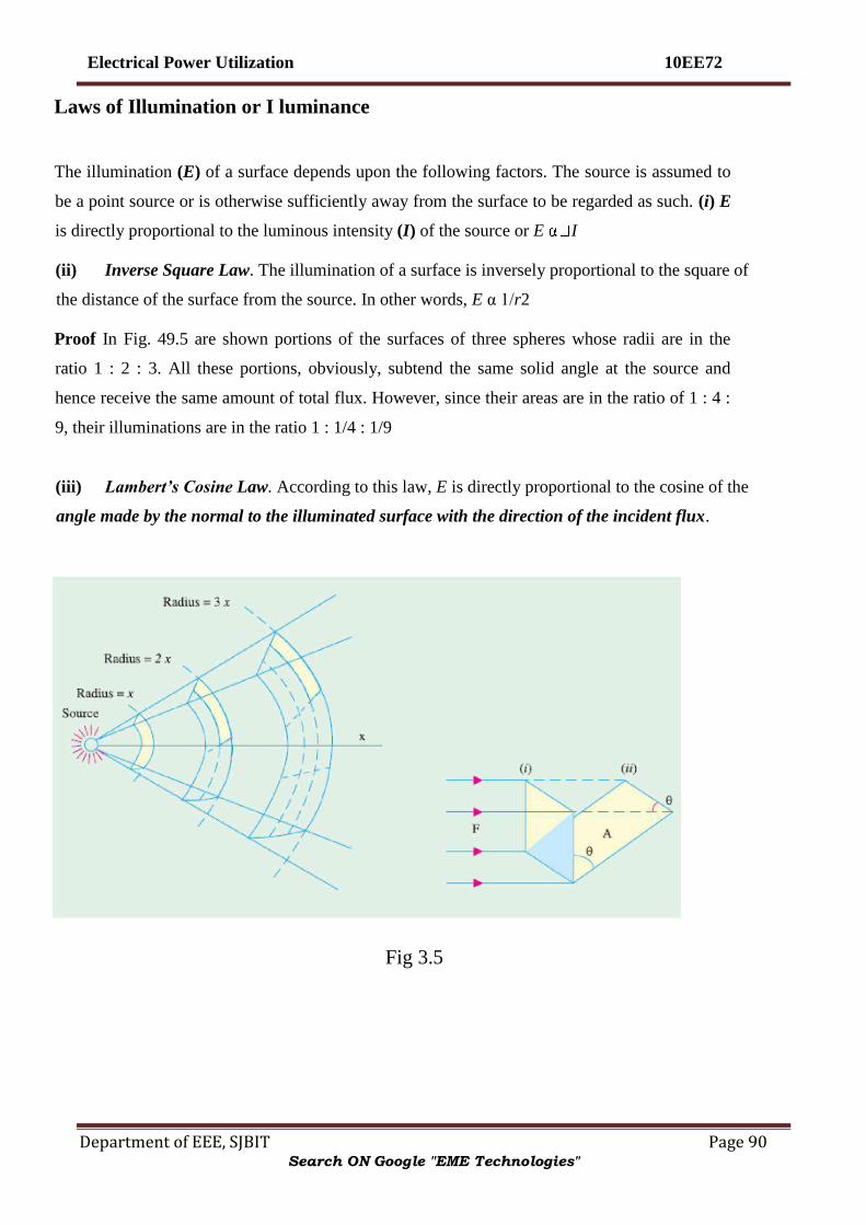
Electrical Power Utilization 10EE72
Department of EEE, SJBIT Page 90
Laws of Illumination or I luminance
The illumination (E) of a surface depends upon the following factors. The source is assumed to
be a point source or is otherwise sufficiently away from the surface to be regarded as such. (i) E
is directly proportional to the luminous intensity (I) of the source or E I
(ii) Inverse Square Law. The illumination of a surface is inversely proportional to the square of
the distance of the surface from the source. In other words, E α 1/r2
Proof In Fig. 49.5 are shown portions of the surfaces of three spheres whose radii are in the
ratio 1 : 2 : 3. All these portions, obviously, subtend the same solid angle at the source and
hence receive the same amount of total flux. However, since their areas are in the ratio of 1 : 4 :
9, their illuminations are in the ratio 1 : 1/4 : 1/9
(iii) Lambert’s Cosine Law. According to this law, E is directly proportional to the cosine of the
angle made by the normal to the illuminated surface with the direction of the incident flux.
Fig 3.5
Search ON Google "EME Technologies"

Electrical Power Utilization 10EE72
Department of EEE, SJBIT Page 91
Proof
The above expression makes the determination of illumination possible at a given point
provided the position and the luminous intensity or candle power (in the given direction) of the
source (or sources) by which it is illuminated are known as illustrated by the following
examples.
Consider a lamp of uniform luminous intensity suspended at a height h above the working plane
as shown in Fig. 49.7. Let us consider the value of illumination at point A immediately below
the lamp and at other points B,C,D etc., lying in the working plane at different distances from A.
As shown in Fig. 3 .6 , let A when in position 1. When this
surface is turned back through an angle , then the flux incident on it is cos Ө. Hence, illumination
of the surface when in position 1 is E = 1 / A . But when in position 2.
Combining all these factors together, we get E = I cos Ө/ r 2 . The unit is lm/m
2 .
Laws Governing Illu mination of Different Sources
Search ON Google "EME Technologies"

Electrical Power Utilization 10EE72
Department of EEE, SJBIT Page 92
E = I /2d
The laws applicable to the illumination produced by the following three types of sources will be
considered. (i) Point Source
As discussed in Art. 3.5, the law governing changes in illumination due to point source of light is E =
I cos Ө/d2.
(ii) Line Source
Provided the line source is of infinite length and of uniform intensity, the illumination at a point lying
on a surface parallel to and facing the line source is given by
where I = luminous intensity normal to the line source (in candles per-meter length of the sources)
where I = luminous intensity normal to the line source (in candles per-meter length of the sources)
However, in practice, the line sources are of finite length, so that the following law applies
where I = candle power per metre length in a direction normal to
the line source
………….49.8(a)
………. 49.8(b)
Search ON Google "EME Technologies"

Electrical Power Utilization 10EE72
Department of EEE, SJBIT Page 93
L is the length of the line source in metres
Polar Curves of C.P. Distribution
All our calculations so far were based on the tacit assumption that the light source was of equal
luminous intensity or candle-power in all directions. However, lamps and other sources of light,
as a rule, do not give uniform distribution in the space surrounding them. If the actual luminous
intensity of a source in various directions be plotted to scale along lines radiating from the
centre of the source at corresponding angles, we obtain the polar curve of the candle power.
Suppose we construct a figure consisting of large number of spokes radiating out from a point
—the length of each spoke representing to some scale the candle power or luminous intensity of
the source in that particular direction. If now we join the
ends of these spokes by some suitable material, say, by linen cloth, then we get a surface whose
shape will represent to scale the three dimensional candle power distribution of the source
placed at the centre. In the ideal case of a point source having equal distribution in all
directions, the surface would bespherical. It would be realized that it is difficult to give a
Search ON Google "EME Technologies"

Electrical Power Utilization 10EE72
Department of EEE, SJBIT Page 94
graphic representation of such a 3-dimensional model in a plane surface. Therefore, as with
engineering drawings, it is usual to draw only one or more elevations and a plan of sections
through the centre of the source. Elevations represent c.p. distribution in the vertical plane and
the plans represent c.p. distribution in horizontal plane. The number of elevations required to
give a complete idea of the c.p. distribution of the source in all directions depends upon the
shape of the plan i.e. on the horizontal distribution. If the distribution is uniform in every
horizontal plane i.e. if the polar curve of horizontal distribution is a circle, then only one vertical
curve is sufficient to give full idea of the space distribution. In Fig.
3.20 are shown two polar curves of c.p. distribution in a vertical plane. Curve 1 is for
Fig 3.21
vacuum type tungsten lamp with zig-zag filament whereas curve 2 is for gas filled tungsten lamp
with filament arranged as a horizontal ring.
If the polar curve is symmetrical about the vertical axis as in the figures given below, then it is
sufficient to give only the polar curve within one semicircle in order to completely define the
Search ON Google "EME Technologies"

Electrical Power Utilization 10EE72
Department of EEE, SJBIT Page 95
distribution of c.p. as shown in Fig. 3.21. The curves 1 and 2 are as in Fig. 3.20, curves 3 is for
d.c. open arc with plain carbons and curve 4 is for a.c. arc with plain carbons. However, if the
source and/or reflector are not symmterical about vertical axis, it is impossible to represent the
space distribution of c.p. by a single polar diagram and even polar diagrams for two planes at
right angles to each other give no definite idea as to the distribution in the intermediate planes.
Consider a filament lamp with a helmet-type reflector whose axis is inclined and cross-section
elliptical—such reflectors are widely used for lighting shop windows. Fig. 3.22 represents the
distribution of luminous intensity of such source and its reflector in two planes at right angles to
each other. The importance of consideringthe polar curves in different planes when the c.p.
distribution in asymmetrical is even more strikingly depicted by the polar curves in YY plane
and XX plane of a lamp with a special type of reflector designed for street lighting purposes
(Fig. 3.23).
Fig 3.22
Fig 3.33
It would be realized from above that the polar distribution of light from any source can be given any
desired form by using reflectors and/or refractors of appropriate shape.
Search ON Google "EME Technologies"

Electrical Power Utilization 10EE72
Department of EEE, SJBIT Page 96
In Fig. 3.24 is shown the polar curve of c.p. distribution of a straight type of lamp in a horizontal
plane.
Uses of Polar Curves
Polar curves are made use of in determining the M.S.C.P. etc. of a source. They are also used in
determining the actual illumination of a surface i.e. while calculating the illumination in a
particular direction, the c.p. in that particular direction as read from the vertical polar curve,
should be employed.
Determination of M.S.C.P.and M.H.C.P. from Polar Diagrams
In Fig. 3.25 (a) is shown the polar distribution curve of a filament lamp in a horizontal plane and the
polar curve in
Fig. 3.25 (b) represents the c.p. distribution in a vertical plane. It will be seen that the
horizontal candle-power is almost uniform in all directions in that plane. However, in the
vertical plane, there is a large variation in the candle power which falls to zero behind the cap of
the lamp. The curve in Fig. 3.25 (a)
Fig 3.24
has been drawn with the help of a photometer while the lamp is rotated about a vertical axis,
say, 10° at a time. But the curve in Fig. 49.25 (b) was drawn while the lamp was rotated in a
vertical plane about a horizontal axis passing through the centre of the filament. The M.H.C.P.
is taken as the mean of the readings in Fig. 49.25 (a). However, a more accurate result can be
Search ON Google "EME Technologies"

Electrical Power Utilization 10EE72
Department of EEE, SJBIT Page 97
obtained by plotting candle power on an angular base along the rectangular axes and by
determining the mean height of the curve by the mid-ordinate or by Simpson‘s rule. The
M.S.C.P. of the lamp can be obtained from the vertical polar curve of Fig. 3.25 (b) by
Rousseau‘s construction as explained below :
Only half of the vertical polar curve is shown in the figure (Fig. 49.26) since it is symmetrical
about the vertical axis. With O is the centre and radius OR equal to the maximum radius of the
polar curve, a semi-circle LRM is drawn. A convenient number of points on this semi-circle (say
10° points) are projected onto any vertical plane as shown. For example, points a,b,c etc. are
projected to d,e,f and so on. From point d, the horizontal line dg is drawn equal to the intercept
OA of the polar diagram on the radius oa. Similarly, eh = OB, fk = OC and so on. The points g,
h, k etc., define the
Fig 3.25
Rousseau figure. The average width w of this figure represents the M.S.C.P. to the same scale as
that of the candle powers in the polar curve. The average width is obtained by dividing the
Rousseau area by the base of the Rousseau figure i.e. length lm which is the projection of the
semi-circle LM on the
Search ON Google "EME Technologies"

Electrical Power Utilization 10EE72
Department of EEE, SJBIT Page 98
lamp with its axis vertical and taking photometer readings in the horizontal plane while the lamp
is rotated about its axis in steps of 10° or so. A definite ratio exists between the M.H.C.P. and
M.S.C.P. of each particular type of filament. M.S.C.P. of a lamp can be found by multiplying
M.H.C.P. by a factor known as spherical reduction factor which, as defined earlier, is
For the particular lamp considered, f = 430/80 = 0.54 (approx.)
Typical values of this factor are : Ordinary vacuum-type tungsten lamp having zig-zag filament 0.76
-filled tungsten lamp with filament in the form of broad shallow V
Gas-
the present case,
= 5,405 lm
Integrating Sphere or Photometer
vertical axis. The area may be determined by Simpson‘s rule or by using a planimeter
As explained earlier, the M.H.C.P. of an incandes cent lamp can be easily obtained by mounting the
Search ON Google "EME Technologies"

Electrical Power Utilization 10EE72
Department of EEE, SJBIT Page 99
The M.S.C.P. is usually measured by means of an integrating photometer, the most accurate
form of which consists of a hollow sphere (as originally proposed by Ulbricht) whose diameter
is large (at least 6 times) as compared to that of the lamp under test. The interior surface of the
hollow sphere is whitened by means of a special matt white paint. When the lamp is placed
inside the sphere (not
Fig 3.27
necessarily at its centre) then due to successive reflections, its light is so diffused as to produce a
uniform illumination over the whole surface. At some point, a small matt opal-glass window,
shaded from the direct rays of the source, is made in the hollow sphere. The brightness of the
matt opal glass is proportional to that of the interior surface of the sphere.
By using a suitable illumination photometer, the illumination of the window can be measured which
can be used to find out the total flux emitted by the source.
Total flux = illumination (1m/m2 2
)
candela
Theory. In Fig. 3.28 is shown a light source L of luminous intensity I candela and having a total
flux output of FL placed at the centre of an integrating sphere of radius r and reflec
Let EA and EB represent the illuminations at two points A and B, each of infinitely small area da
and db respectively and distance m apart. We will now consider total illumination (both direct
and reflected) at point A. Obviously EA directly due to L = I/r2 EB directly due to L = I/r2
Search ON Google "EME Technologies"

Electrical Power Utilization 10EE72
Department of EEE, SJBIT Page 100
Hence, total illumination at A from direct and reflected lights is
If A is shielded from lamp L, then its illumination is proportional to FL because is a
constant factor. Obviously, if either brightness or illumination at one point in the sphere is
measured, it would be proportional to the light output of the source. This fact is made use of
while using this sphere as a globe photometer.
Floodlighting
It means ‗flooding‘ of large surfaces with the help of light from powerful projectors. Flooding is
employed for the following purposes :
1. For aesthetic purposes as for enhancing the beauty of a building by night i.e. flood lighting of ancient
monuments, religious buildings on important festive occassions etc.
Luminous intensity of B in the direction of A is
Search ON Google "EME Technologies"

Electrical Power Utilization 10EE72
Department of EEE, SJBIT Page 101
2. For advertising purposes i.e. flood lighting, huge hoardings and commercial buildings.
3. For industrial and commercial purposes as in the case of railway yards, sports stadiums and quarries
etc.
Usually, floodlight projectors having suitable reflectors fitted with standard 250-, 500, or 1,000-
watt gas-filled tungsten lamps, are employed. One of the two typical floodlight installations
often used is as shown in
Fig. 3.44(a). The projector is kept 15 m to 30 m away from the surface to be floodlighted and
provides approximately parallel beam having beam spread of 25° to 30°. Fig. 3.44(b) shows the
case when the projector cannot be located away from the building. In that case, an asymmetric
reflector is used which directs more intense light towards the top of the building. The total
EA/ p.
However, in the case of flood-lighting, one more factor has to be taken into account. That factor
is known as waste-light factor (W). It is so because when several projectors are used, there is
bound to be a certain amount of overlap and also because some light would fall beyond the
edges of the area to be illuminated. These two factors are taken into account by multiplying the
theoretical value of the flux required by a waste-light factor which has a value of nearly 1.2 for
regular surfaces and about
1.5
for irregular objects like statues etc. Hence, the formula for calculation of total flux required for
floodlighting purposes is
Search ON Google "EME Technologies"

Electrical Power Utilization 10EE72
Department of EEE, SJBIT Page 102
Fig 3.44
Artificial Sources of Light
The different methods of producing light by electricity may, in a board sense, be divided into three
groups.
1. By temperature incandescence. In this method, an electric current is passed through a
filament of thin wire placed in vacuum or an inert gas. The current generates enough heat to
raise the temperature of the filament to luminosity.
Incandescent tungsten filament lamps are examples of this type and since their output depends on the
temperature of their filaments, they are known as temperature radiators.
2. By establishing an arc between two carbon electrodes. The source of light, in their case,
is the incandescent electrode.
3. Discharge Lamps. In these lamps, gas or vapour is made luminous by an electric
discharge through them. The colour and intensity of light i.e. candle-power emitted depends on
the nature of the gas or vapour only. It should be particularly noted that these discharge lamps
are luminiscentlight lamps and do not depend on temperature for higher efficiencies. In this
respect, they differ radically from incandescent lamps whose efficiency is dependent on
temperature. Mercury vapour lamp, sodium-vapour lamp, neon-gas lamp and fluorescent lamps
are examples of light sources based on discharge through gases and vapours.
Search ON Google "EME Technologies"
Electrical Power Utilization 10EE72
Department of EEE, SJBIT Page 103
Incandescent Lamp
An incandescent lamp essentially consists of a fine wire of a high-resistance metal placed in an evacuated
glass bulb and heated to luminosity by the passage of current through it. Such lamps were
* It indicates the divergence of a beam and may be defined as the angle within which the
minimum illumination on a surface normal to the axis of the beam is 1/10th of the maximum.
produced commercially for the first time by Edison in 1879.
His early lamps had filaments of carbonized paper which were, later on, replaced by carbonized
bamboo. They had the disadvantage of negative temperature coefficient of resistivity. In 1905,
the metallized carbon-filament lamps were put in the market whose filaments had a positive
temperature coefficient of resistivity (like metals). Such lamps gave 4 lm/W. At approximately
the same time, osmium lamps were manufactured which had filaments made of osmium which
is very rare and expensive metal. Such lamps had a very fair maintenance of candle-power
during their useful life and an averae efficiency of 5 lm/W. However, osmium filaments were
found to be very fragile.
In 1906 tantalum lamps having filaments of tantalum were produced which had an initial
efficiency of 5 lm/watt. All these lamps were superseded by tungsten lamps which were
commercially produced in about 1937 or so. The superiority of tungsten lies mainly in its ability
to withstand a high operating temperature without undue vaporisation of the filament. The
necessity of high working temperature is due to the fact that the amount of visible radiation
increases with temperature and so does the radiant efficiency of the luminous source. The
melting temperature of tungsten is 3655°K whereas that of osmium is 2972°K and that of
tantalum is 3172°K. Actually, carbon has a higher melting point than tungsten but its operating
temperature is limited to about 2073°K because of rapid vaporization beyond this temperature.
In fact, the ideal material for the filament of incandescent lamps is one which has the following properties :
1. A high melting and hence operating temperature
2. A low vapour pressure
3. A high specific resistance and a low temperature coefficient
4. Ductility and
5. Sufficient mechanical strength to withstand vibrations. Since tungsten possesses practically all the above
mentioned qualities, it is used in almost all modern incandescent lamps. The earlier lamps had a square-
cage type filament supported from a central glass stem enclosed in an evacuated glass bulb.
Search ON Google "EME Technologies"

Electrical Power Utilization 10EE72
Department of EEE, SJBIT Page 104
The object of vacuum was two
fold : (a) to prevent oxidation and
(b) to minimize loss of heat by convection and the consequent lowering of filament temperature.
However, vacuum favoured the evaporation of the filament with the resulting blackening of the
lamp so that the operating temperature had to be kept as low as 2670º K with serious loss in
luminous efficiency
Fig 3.46
It was, later on, found that this difficulty could be solved to a great extent by inserting a
chemically inert gas like nitrogen or argon. The presence of these gases within the glass bulb
decreased the evaporation of the filament and so lengthened its life. The filament could now be
run at a relatively higher temperature and hence higher luminous efficiency could be realized. In
practice, it was found that an admixture of 85% argon and about 15 percent nitrogen gave the
best results. However, introduction of gas led to another difficulty i.e. loss of heat due to
convection which offsets the additional increase in efficiency. However, it was found that for
securing greater efficiency, a concentrated filament having a tightly-wound helical construction
was necessary. Such a coiled filament was less exposed to circulating gases, its turns supplying
heat to each other and further the filament was mechanically stronger. The latest improvement is
that the coiled filament is itself
‗coiled‘ resulting in ‗coiled-coil‘ filament Fig. 3.46 (a) which leads to further concentrating the
heat, reducing the effective exposure to gases and allows higher temperature operation, thus
giving greater efficiency. The construction of a modern coiledcoil gas-filled filament lamp is
shown in Fig. 49.46
(b). The lamp has a ‗wreath‘ filament i.e. a coiled filament arranged in the form of a wreath on radial
supports
Search ON Google "EME Technologies"

Electrical Power Utilization 10EE72
Department of EEE, SJBIT Page 105
Filament Dimensions
There is found to be a definite relation between the diameter of a given filament and the current.
Consider a filament operating at a fixed temperature and efficiency.
Then since no heat is being utilized for further raising the temperature, all the heat produced in a
given time is mostly lost by radiation (if vacuum is good). In other words, Heat produced per
second = heat lost per second by radiation
where, I = filament current in amperes, l = filament length A
= filament cross-section d = filament diameter r = resistivity
of filament material at the working temperature.
Heat radiated per second from the surface is proportional to the area of the surface and emissivity
of the material
It would be noticed that the above expressions are similar to those concerning fusing current of a
given material under stated conditons (Preece‘s Rule).
Moreover, for two filaments working at the same temperature, the flux per unit area is the same.
Denoting their lengths by l1 and l2 and their diameters by d1 and d2 respectively, we have,
l1 d1 αl2 d2or l1d1 = l2d2 = constant.
Search ON Google "EME Technologies"

Electrical Power Utilization 10EE72
Department of EEE, SJBIT Page 106
Incandescent Lamp Characteristics
The operating characteristics of an incandescent lamp are materially affected by departure from
its normal working voltage. Initially, there is a rapid heating up of the lamp due to its low
thermal capacity, but then soon its power intake becomes steady. If the filament resistance were
not dependent on its temperature, the rate of generation of heat would have been directly
proportional to the square of voltage applied across the lamp. However, because of (i) positive
temperature coefficient of resistance and (ii) complex mechanism of heat transfer from filament
to gas, the relations between the lamp characteristics and its voltage are mostly experimental.
Some of the characteristics of gasfilled lamps are given below.
Search ON Google "EME Technologies"

Electrical Power Utilization 10EE72
Department of EEE, SJBIT Page 107
Fig 3.47
It is found that candle power or lumen output of the lamp varies with the voltage as lumen Output
αV3.3
.
(ii) Variation of lumen output in terms of current is given by : lumen output αI5
(iii) V13
(iv) Wattage is given by W V1.43
(v) V2
The characteristic curves are plotted in Fig. 49.47. The life characteristic is very revealing.
Even a small undervoltage considerably increases its life whereas overvoltage of as small a value
as 5% shortens its life by 50%.
High-pressure Mercury Vapour Lamp
Like sodium-vapour lamp, this lamp is also classified as electric discharge lamp in which light is
produced by gaseous conduction. Such a lamp usually consists of two bulbs — an arc-tube
containing the electric discharge and an outer bulb which protects the arc-tube from changes in
temperature. The
Search ON Google "EME Technologies"

Electrical Power Utilization 10EE72
Department of EEE, SJBIT Page 108
inner tube or arc tube A is made of quartz (or hard glass) the outer bulb B of hard glass. As
shown in Fig. 3.49, the arc tube contains a small amount of mercury and argon gas and houses
three electrodes D, E and S. The main electrodes are D and E whereas S is the auxiliary starting
electrode. S is connected through a high resistance R
situated at the outer end of the tube. The main electrodes consist of tungsten coils with electron-
emitting coating or elements of thorium metal.
When the supply is switched on, initial discharge for the few seconds is established in the argon
gas between D and S and then in the argon between D and E. The heat produced due to this
discharge through the gas is sufficient to vaporise mercury. Consequently, pressure inside A
increases to about one or two atmospheres and the p.d. across D and E grows from about 20 to
150 V, the operation taking about 5-7 minutes. During this time, discharge is established
through the mercury vapours which emit greenish-blue light.
Fig 3.48
The choke serves to limit the current drawn by the discharge tube A to a safe limit and capacitor C
helps to improve the power factor of the circuit.
True colour rendition is not possible with mercury vapour lamps since there is complete absence
of red-light from their radiations. Consequently, red objects appear black, all blues appear
mercuryspectrum blue and all greens the mercury-spectrum green with the result that colour
values are distorted.
Correction for colour distortion can be achieved by
1. Using incandescent lamps (which are rich in red light) in combination with the mercury lamps.
2. Using colour-corrected mercury lamps which have an inside phosphor coat to add red colour to the
mercury spectrum.
Search ON Google "EME Technologies"

Electrical Power Utilization 10EE72
Department of EEE, SJBIT Page 109
Stroboscopic (Flickering) effect in mercury vapour lamps is caused by the 100 on and off arc strikes
when the lamps are used on the 50-Hz supply. The effect may be minimized by
1. Using two lamps on lead-lag transformer
2. Using three lamps on separated phases of a 3-phase supply
and 3. Using incandescent lamps in combination with
mercury lamps.
In the last few years, there has been tremendous improvement in the construction and operation
of mercury-vapour lamps, which has increased their usefulness and boosted their application for
all types of industrial lighting, floodlighting and street lighting etc. As compared to an
incandescent lamp, a mercury-vapour lamp is (a) smaller in size (b) has 5 to 10 times longer
operating life and (c) has 3 times higher efficiency i.e. 3 times more light output for given
electrical wattage input.
Typical mercury-vapour lamp applications are :
1. High-bay industrial lighting — where high level illumination is required and colour rendition is
not important.
2. Flood-lighting and street-lighting
Fluorescent Lamp Circuit with Thermal Switch
The circuit arrangement is shown in Fig. 3.52. The switch has a bimetallic strip close to a
resistance R which produces heat. The switch is generally enclosed in hydrogen-filled glass
bulb G. The two switch electrodes E1 and E2 are normally closed when the lamp is not in
operation. When normal supply is switched on, the lamp filament electrodes A and B are
connected together
through the thermal switch and a large current passes through them. Consequently, they are
heated to incandescence. Meanwhile heat produced in resistance R causes the bimetallic strip E2
to break contact. The inductive surge of about 1000 V produced by the choke is sufficient to
start dischargethrough mercury vapours as explained in Art. 3.27.The heat produced in R keeps
the switch contacts
E1 and E2 open during the time lamp is in operation.
Search ON Google "EME Technologies"

Electrical Power Utilization 10EE72
Department of EEE, SJBIT Page 110
Comparison of Different Light Sources
1. Incandescent Lamps. They have instantaneous start and become momentarily off when
the supply goes off. The colour of their light is very near the natural light. Their initial cost of
installation is minimum but their running cost is maximum. They work equally well both on d.c.
and a.c. supply and frequent switching does not affect their life of operation. Change of supply
voltage affects their efficiency, output and life in a very significant way. They have an average
working life of 1000 hours and luminous efficiency of 12 lm/W. Since their light has no
stroboscopic effects, the incandescent lamps are suitable for domestic, industrial, street lighting
and floodlights etc. They are available in a wide range of voltage ratings and, hence are used in
automobiles, trains, emergency lights, aeroplanes and signals for railways etc.
2. Flourescent Lamps. They have a reaction time of one second or a little more at the start.
They go off and restart when the supply is restored. The colour of their light varies with the
phosphor coating. Their initial cost of installation is maximum but running cost is minimum.
Since stroboscopic effect is present, they are suitable for semi-direct lighting, domestic,
industrial, commercial, roads and halls etc. Change in voltage affects their starting although
light output does not change as remarkably as in the case of incandescent lamps. Colour of their
light changes with the different phosphor coating on the inner side of the tube. Frequent
switching affects their life period. They have quite high utility but their voltage rating is limited.
Hence, their use is confined to mains voltage or complicated inverter circuits which convert 12
Search ON Google "EME Technologies"

Electrical Power Utilization 10EE72
Department of EEE, SJBIT Page 111
V d.c. into high volt d.c.. They have an average working life of 4000 hours and a luminous
efficiency of 40 lm/W.
3. Mercury Vapour Lamps. They take 5 to 6 minutes for starting. They go off and cannot
be restarted after the recovery of the voltage till the pressure falls to normal. They suffer from
high colour distortion. Their initial cost of installation is high but lesser than that of flourescent
lamps. Their running cost is much less than incandescent lamps but higher than flourescent
tubes for the same levels of illumination. Stroboscopic effect is present in their light. They are
suitable for open space like yards, parks and highway lighting etc. Change in voltage effects
their starting time and colour of radiations emitted by them. Switching does not affect their life
period. They have very limited utility that too on mains voltage. They are suitable for vertical
position of working. They have an average working life of 3000 hours and an efficiency of 40
lm/W.
4. Sodium Vapour Lamps. They have a starting time of 5 to 6 minutes. They go off and
cannot be restarted after the recovery of the voltage till its value falls to the normal value. The
colour of their light is yellowish and produces colour distortion.Their initial cost of installation
is maximum although their running cost is less than for filament lamps but more than for
flourescent lamps. Theyhave stroboscopic effect and are suitable for use in open spaces,
highways and street lighting etc. Change in voltage affects their starting time and colour of their
radiations. They work on a.c. voltage and frequent switching affects their life. They are not
suitable for local lighting. The colour of their light cannot be changed. They are very suitable
for street lighting purposes. Their position of working is horizontal. They have a working life of
about 3000 hours and efficiency of 60-70 lm/W.
Expected Questions
1. A directly beneath the source. How far is B from A if the illumination at B is only 1/10 as great as at
A?Let the intensity of the lamp be I and the distance between A and B be x metres as shown in
Search ON Google "EME Technologies"

Electrical Power Utilization 10EE72
Department of EEE, SJBIT Page 112
Illumination at point A, EA = I/102 = I/100 lux Illumination at point B,
2. A corridor is lighted by 4 lamps spaced 10 m apart and suspended at a height of 5 m above the centre
line of the floor. If each lamp gives 200 C.P. in all directions below the horizontal, find the
illumination at the point on the floor mid-way between the second and third lamps.
3. Two lamps A and B of 200 candela and 400 candela respectively are situated 100 m apart. The height
of A above the ground level is 10 m and that of B is 20 m. If a photometer is placed at the centre of
the line joining the two lamp posts, calculate its reading.
Solution: When the illumination photometer is placed at the centre point, it will read the value of
combined illumination produced by the two lamps
4. The average luminous output of an 80-W fluorescent lamp 1.5 metre in length and 3.5 cm diameter is
3300 lumens. Calculate its average brightness. If the auxiliary gear associated with the lamp
consumes a load equivalent to 25 percent of the lamp, calculate the cost of running a twin unit for
2500 hours at 30 paise per kWh.
5. A small area 7.5 m in diameter is to be illuminated by a lamp suspended at a height of 4.5 m over the
centre of the area. The lamp having an efficiency of 20 lm/w is fitted with a reflector which directs
the light output only over the surface to be illuminated, giving uniform candle power over this angle.
Utilisation coefficient = 0.40. Find out the wattage of the lamp. Assume 800 lux of illumination level
from the lamp.
6. A room 8 m × 12 m is lighted by 15 lamps to a fairly uniform illumination of 100 lm/m2. Calculate
the utilization coefficient of the room given that the output of each lamp is 1600 lumens.
7. The illumination in a drawing office 30 m × 10 m is to have a value of 250 lux and is to be provided
by a number of 300-W filament lamps. If the coefficient of utilization is 0.4 and the depreciation
factor 0.9, determine the number of lamps required. The luminous efficiency of each lamp is 14 lm/W
8. Find the total saving in electrical load and percentage increase in illumination if instead of using
twelve 150 W tungsten-filament lamps, we use twelve 80 W fluorescent tubes. It may be assumed that
(i) there is a choke loss of 25 per cent of rated lamp wattage (ii) average luminous efficiency
throughout life for each lamp is 15 lm/W and for each tube 40 lm/W and (iii) coefficient of utilization
remains the same in both cases
Search ON Google "EME Technologies"
Electrical Power Utilization 10EE72
Department of EEE, SJBIT Page 113
9. A football pitch 120 m × 60 m is to be illuminated for night play by similar banks of equal 1000 W
lamps supported on twelve towers which are distributed around the ground to provide approximately
uniform illumination of the pitch. Assuming that 40% of the total light emitted reaches the playing
pitch and that an illumination of 1000 lm/m2 is necessary for television purposes, calculate the
number of lamps on each tower. The overall efficiency of the lamp is to be taken as 30 lm/W.
10. If the filament of a 32 candela, 100-V lamp has a length l and diameter d, calculate the length and
diameter of the filament of a 16 candela 200-V lamp, assuming that the two lamps run at the same
intrinsic brilliance.
11. An incandescent lamp has a filament of 0.005 cm diameter and one metre length. It is required to
construct another lamp of similar type to work at double the supply voltage and give half the candle
power. Assuming that the new lamp operates at the same brilliancy, determine suitable dimensions
for its filament.
12. A 60 candle power, 250-V metal filament lamp has a measured candle power of 71.5 candela at 260
V and 50 candela at 240 V. (a) Find the constant for the lamp in the expression C = aVb where C =
candle power and V = voltage. (b) Calculate the change of candle power per volt at 250 V. Determine
the percentage variation of candle power due to a voltage variation of æ 4% from the normal value.
Search ON Google "EME Technologies"

Electrical Power Utilization 10EE72
Department of EEE, SJBIT Page 114
PART B
UNIT-5, 6 & 7
ELECTRIC TRACTION
Introduction: By electric traction is meant locomotion in which the driving (or tractive) force is
obtained from electric motors. It is used in electric trains, tramcars, trolley buses and diesel-electric
vehicles etc.
Electric traction has many advantages as compared to other non-electrical systems of traction including
steam traction.
Traction Systems
Broadly speaking, all traction systems may be classified into two categories :
(a) Non-electric traction systems
They do not involve the use of electrical energy at any stage. Examples are : steam engine drive used
in railways and internal-combustion-engine drive used for road transport.
(b) Electric traction systems
They involve the use of electric energy at some stage or the other. They may be further subdivided into
two groups :
1. First group consists of self-contained vehicles or locomotives. Examples are : battery-electric drive
and diesel-electric drive etc.
2. Second group consists of vehicles which receive electric power from a distribution network fed at
suitable points from either central power stations or suitably-spaced sub-stations.
Examples are : railway electric locomotive fed from overhead ac supply and tramways and trolly buses
supplied with dc supply.
Search ON Google "EME Technologies"

Electrical Power Utilization 10EE72
Department of EEE, SJBIT Page 115
Direct Steam Engine Drive
Though losing ground gradually due to various reasons, steam locomotive is still the most
widelyadopted means of propulsion for railway work. Invariably, the reciprocating engine is
employed because
1. it is inherently simple.
2. connection between its cylinders and the driving wheels is simple.
3. its speed can be controlled very easily.
However, the steam locomotive suffers from the following disadvantages :
1. since it is difficult to install a condenser on a locomotive, the steam engine runs non-condensing and,
therefore, has a very low thermal efficiency of about 6-8 percent.
2. it has strictly limited overload capacity.
3. it is available for hauling work for about 60% of its working days, the remaining 40% being spent in
preparing for service, in maintenance and overhaul.
Diesel-electric Drive
It is a self-contained motive power unit which employs a diesel engine for direct drive of a dc
generator. This generator supplies current to traction motors which are geared to the driving axles. In
India, diesel locomotives were introduced in 1945 for shunting service on broad guage (BG) sections
and in 1956 for high-speed main-line operations on metre-guage (MG) sections. It was only in 1958
that Indian Railways went in for extensive main-line dieselisation.* Diesel-electric traction has the
following advantages :
1. no modification of existing tracks is required while converting from steam to diesel-electric traction.
2. it provides greater tractive effort as compared to steam engine which results in higher starting
acceleration.
3. it is available for hauling for about 90% of its working days.
4. diesel-electric locomotive is more efficient than a steam locomotive (though less efficient than an
electric locomotive). Disadvantages
1. for same power, diesel-electric locomotive is costlier than either the steam or electric locomotive.
2. overload capacity is limited because diesel engine is a constant-kW output prime mover.
3. life of a diesel engine is comparatively shorter.
Search ON Google "EME Technologies"

Electrical Power Utilization 10EE72
Department of EEE, SJBIT Page 116
4. diesel-electric locomotive is heavier than plain electric locomotive because it carries the main
engine, generator and traction motors etc.
5. regenerative braking cannot be employed though rheostatic braking can be.
Battery-electric Drive
In this case, the vehicle carries secondary batteries which supply current to dc motors used for driving
the vehicle. Such a drive is well-suited for shunting in railway yards, for traction in mines, for local
delivery of goods in large towns and large industrial plants. They have low maintenance cost and are
free from smoke. However, the scope of such vehicles is limited because of the small capacity of the
batteries and the necessity of charging them frequently.
Advantages of Electric Traction
As compared to steam traction, electric traction has the following advantages :
1. Cleanliness. Since it does not produce any smoke or corrosive fumes, electric traction is most
suited for underground and tube railways. Also, it causes no damage to the buildings and other
apparatus due to the absence of smoke and flue gases.
2. Maintenance Cost. The maintenance cost of an electric locomotive is nearly 50% of that for a
steam locomotive. Moreover, the maintenance time is also much less.
3. Starting Time. An electric locomotive can be started at a moment's notice whereas a steam
locomotive requires about two hours to heat up.
4. High Starting Torque. The motors used in electric traction have a very high starting torque.
Hence, it is possible to achieve higher accelerations of 1.5 to 2.5 km/h/s as against 0.6 to 0.8 km/h/s
in steam traction. As a result, we are able to get the following additional advantages:
(i) high schedule speed
(ii) increased traffic handling capacity
(iii)because of (i) and (ii) above, less terminal space is required—a factor of great importance in urban
areas.
Search ON Google "EME Technologies"

Electrical Power Utilization 10EE72
Department of EEE, SJBIT Page 117
5. Braking. It is possible to use regenerative braking in electric traction system. It leads to the
following advantages :
(i) about 80% of the energy taken from the supply during ascent is returned to it during descent.
(ii) goods traffic on gradients becomes safer and speedier.
(iii)since mechanical brakes are used to a very small extent, maintenance of brake shoes, wheels, tyres
and track rails is considerably reduced because of less wear and tear.
6. Saving in High Grade Coal. Steam locomotives use costly high-grade coal which is not so
abundant. But electric locomotives can be fed either from hydroelectric stations or pit-head thermal
power stations which use cheap low-grade coal. In this way, high-grade coal can be saved for
metallurgical purposes.
7. Lower Centre of Gravity. Since height of an electric locomotive is much less than that of a
steam locomotive, its centre of gravity is comparatively low. This fact enables an electric locomotive
to negotiate curves at higher speeds quite safely.
8. Absence of Unbalanced Forces. Electric traction has higher coefficient of adhesion since there
are no unbalanced forces produced by reciprocating masses as is the case in steam traction. It not only
reduces the weight/kW ratio of an electric locomotive but also improves its riding quality in addition
to reducing the wear and tear of the track rails.
Disadvantages of Electric Traction
1. The most vital factor against electric traction is the initial high cost of laying out overhead electric
supply system. Unless the traffic to be handled is heavy, electric traction becomes uneconomical.
2. Power failure for few minutes can cause traffic dislocation for hours.
3. Communication lines which usually run parallel to the power supply lines suffer from electrical
interference. Hence, these communication lines have either to be removed away from the rail track
or else underground cables have to be used for the purpose which makes the entire system still more
expensive.
4. Electric traction can be used only on those routes which have been electrified. Obviously, this
restriction does not apply to steam traction.
Search ON Google "EME Technologies"

Electrical Power Utilization 10EE72
Department of EEE, SJBIT Page 118
5. Provision of a negative booster is essential in the case of electric traction. By avoiding the flow of
return currents through earth, it curtails corrosion of underground pipe work and interference with
telegraph and telephone circuits.
Systems of Railway Electrification
Presently, following four types of track electrification systems are available:
1. Direct current system—600 V, 750 V, 1500 V, 3000 V
2. Single-phase ac system—15-25 kV, 16 23, 25 and 50 Hz
3. Three-phase ac system—3000-3500 V at 16 2 3 Hz
4. Composite system—involving conversion of single-phase ac into 3-phase ac or dc.
Direct Current System
Direct current at 600-750 V is universally employed for tramways in urban areas and for many
suburban railways while 1500-3000 V dc is used for main line railways. The current collection is
from third rail (or conductor rail) up to 750 V, where large currents are involved and from overhead
wire for 1500 V and 3000 V, where small currents are involved. Since in majority of cases, track (or
running) rails are used as the return conductor, only one conductor rail is required. Both of these
contact systems are fed from substations which are spaced 3 to 5 km for heavy suburban traffic
and40-50 km for main lines operating at higher voltages of 1500 V to 3000 V. These sub-stations
themselves receive power from 110/132 kV, 3-phase network (or grid). At these substations, this
high-voltage 3-phase supply is converted into low-voltage 1-phase supply with the help of Scott
connected or V-connected 3-phase transformers (Art. 31.9). Next, this low ac voltage is converted
into the required dc voltage by using suitable rectifiers or converters (like rotary converter, mercury
arc,
metal or semiconductor rectifiers). These substations are usually automatic and are remote controlled.
The dc supply so obtained is fed via suitable contact system to the traction motors which are either dc
series motors for electric locomotive or compound motors for tramway and trolley buses where
regenerative braking is desired.
It may be noted that for heavy suburban service, low voltage dc system is undoubtedly superior to
1phase ac system due to the following reasons:
Search ON Google "EME Technologies"
Electrical Power Utilization 10EE72
Department of EEE, SJBIT Page 119
1. dc motors are better suited for frequent and rapid acceleration of heavy trains than ac motors.
2. dc train equipment is lighter, less costly and more efficient than similar ac equipment.
3. when operating under similar service conditions, dc train consumes less energy than a 1-phase ac
train.
4. the conductor rail for dc distribution system is less costly, both initially and in maintenance than the
high-voltage overhead ac distribution system.
5. dc system causes no electrical interference with overhead communication lines.
The only disadvantage of dc system is the necessity of locating ac/dc conversion sub-stations at
relatively short distances apart.
Single-Phase Low-frequency AC System
In this system, ac voltages from 11 to 15 kV at 23 16 or 25 Hz are used. If supply is from a generating
station exclusively meant for the traction system, there is no difficulty in getting the electric supply of
23 16 or 25 Hz. If, however, electric supply is taken from the high voltage transmission lines at 50
Hz, then in addition to step-down transformer, the substation is provided with a frequency converter.
The frequency converter equipment consists of a 3-phase synchronous motor which drives a I-phase
alternator having or 25 Hz frequency.
The 15 kV 23 16 or 25 Hz supply is fed to the electric locomotors via a single over-head wire (running
rail providing the return path).
A step-down transformer carried by the locomotive reduces the 15-kV voltage to 300-400 V for
feeding the ac series motors. Speed regulation of ac series motors is achieved by applying variable
voltage from the tapped secondary of the above transformer. Low-frequency ac supply is used
because apart from improving the commutation properties of ac motors, it increases their efficiency
and power factor. Moreover, at low frequency, line reactance is less so that line impedance drop and
hence line voltage drop is reduced. Because of this reduced line drop, it is feasible to space the
substations 50 to 80 k
Three-phase Low-frequency AC System
Search ON Google "EME Technologies"

Electrical Power Utilization 10EE72
Department of EEE, SJBIT Page 120
It uses 3-phase induction motors which work on a 3.3 kV, 23
16 Hz supply. Sub-stations receive power at a very high voltage from 3-phase transmission lines at
the usual industrial frequency of 50 Hz. This high voltage is stepped down to 3.3 kV by transformers
whereas frequency is reduced from 50 Hz to 23 16 Hz by frequency converters installed at the
substations. Obviously, this system employs two overhead contact wires, the track rail forming the
third phase (of course, this leads to insulation difficulties at the junctions). Induction motors used in
the system are quite simple and robust and give trouble-free operation.
They possess the merits of high efficiency and of operating as a generator when driven at speeds
above the synchronous speed. Hence, they have the property of automatic regenerative braking during
the descent on gradients. However, it may be noted that despite all its advantages, this system has not
found much favor and has; in fact, become obsolete because of it‘s certain inherent limitations given
below:
1. The overhead contact wire system becomes complicated at crossings and junctions.
2. constant-speed characteristics of induction motors are not suitable for traction work.
3. Induction motors have speed/torque characteristics similar to dc shunt motors. Hence, they are not
suitable for parallel operation because, even with little difference in rotational speeds caused by
unequal diameters of the wheels, motors will becomes loaded very unevenly.
Composite System
Such a system incorporates good points of two systems while ignoring their bad points. Two such
composite systems presently in use are:
1. 1-phase to 3-phase system also called Kando system
2. 1-phase to dc system.
Kando System
In this system, single-phase 16-kV, 50 Hz supply from the sub-station is picked up by the locomotive
through the single overhead contact wire. It is then converted into 3-phase ac supply at the same
frequency by means of phase converter equipment carried on the locomotives. This 3-phase supply is
then fed to the 3-phase induction motors.
Search ON Google "EME Technologies"

Electrical Power Utilization 10EE72
Department of EEE, SJBIT Page 121
As seen, the complicated overhead two contact wire arrangement of ordinary 3-phase system is
replaced by a single wire system. By using silicon controlled rectifier as inverter, it is possible to get
variable-frequency 3-phase supply at 1/2 to 9 Hz frequency. At this low frequency, 3-phase motors
develop high starting torque without taking excessive current. In view of the above, Kando system is
likely to be developed further.
Single-phase AC to DC System
This system combines the advantages of high-voltage ac distribution at industrial frequency with the
dc series motors traction. It employs overhead 25-kV, 50-Hz supply which is stepped down by the
transformer installed in the locomotive itself. The low-voltage ac supply is then converted into dc
supply by the rectifier which is also carried on the locomotive. This dc supply is finally fed to dc
series traction motor fitted between the wheels. The system of traction employing 25-kV, 50-Hz,
1phase ac supply has been adopted for all future track electrification in India.
Advantages of 25-kV, 50-Hz AC System
Advantages of this system of track electrification over other systems particularly the dc system are as
under :
1. Light Overhead Catenary
Since voltage is high (25 kV), line current for a given traction demand is less. Hence, crosssection of
the overhead conductors is reduced. Since these small-sized conductors are light, supporting
structures and foundations are also light and simple. Of course, high voltage needs higher insulation
which increases the cost of overhead equipment (OHE) but the reduction in the size of conductors has
an overriding effect.
2. Less Number of Substations
Since in the 25-kV system, line current is less, line voltage drop which is mainly due to the resistance
of the line is correspondingly less. It improves the voltage regulation of the line which fact makes
larger spacing of 50-80 km between sub-stations possible as against 5-15 km with 1500 V dc system
and 15-30 km with 3000 V dc sysem. Since the required number of substations along the track is
considerably reduced, it leads to substantial saving in the capital expenditure on track electrification.
3. Flexibility in the Location of Substations
Larger spacing of substations leads to greater flexibility in the selection of site for their proper
location. These substations can be located near the national high-voltage grid which, in our country,
Search ON Google "EME Technologies"

Electrical Power Utilization 10EE72
Department of EEE, SJBIT Page 122
fortunately runs close to the main railway routes. The substations are fed from this grid thereby
saving the railway administration lot of expenditure for erecting special transmission lines for their
substations. On the other hand, in view of closer spacing of dc substations and their far away location,
railway administration has to erect its own transmission lines for taking feed from the national grid to
the substations which consequently increases the initial cost of electrification.
4. Simplicity of Substation Design
In ac systems, the substations are simple in design and layout because they do not have to install and
maintain rotary converters or rectifiers as in dc systems. They only consist of static transformers
alongwith their associated switchgear and take their power directly from the high-voltage national
grid running over the length and breadth of our country. Since such sub-stations are remotely
controlled, they have few attending personnel or even may be unattended.
5. Lower Cost of Fixed Installations The cost of fixed installations is much less for 25 kV ac system as compared to dc system. In fact,
cost is in ascending order for 25 kV ac, 3000 V dc and 1500 V dc systems. Consequently, traffic
densities for which these systems are economical are also in the ascending order
6. Higher Coefficient of Adhesion
The straight dc locomotive has a coefficient of adhesion of about 27% whereas its value for ac
rectifier locomotive is nearly 45%. For this reason, a lighter ac locomotive can haul the same load as
a heavier straight dc locomotive. Consequently, ac locomotives are capable of achieving higher
speeds in coping with heavier traffic.
7. Higher Starting Efficiency
An ac locomotive has higher starting efficiency than a straight dc locomotive. In dc locomotive
supply voltage at starting is reduced by means of ohmic resistors but by on-load primary or secondary
tap-changer in ac locomotives.
Search ON Google "EME Technologies"
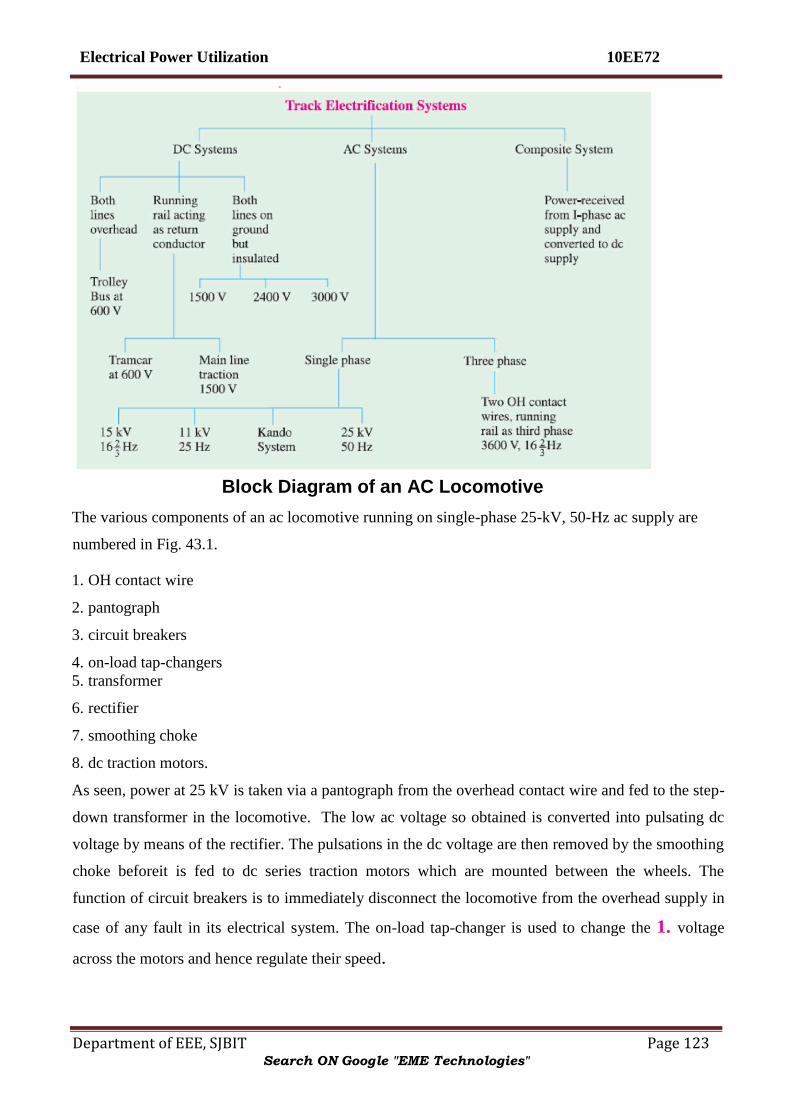
Electrical Power Utilization 10EE72
Department of EEE, SJBIT Page 123
Block Diagram of an AC Locomotive
The various components of an ac locomotive running on single-phase 25-kV, 50-Hz ac supply are
numbered in Fig. 43.1.
1. OH contact wire
2. pantograph
3. circuit breakers
4. on-load tap-changers
5. transformer
6. rectifier
7. smoothing choke
8. dc traction motors.
As seen, power at 25 kV is taken via a pantograph from the overhead contact wire and fed to the step-
down transformer in the locomotive. The low ac voltage so obtained is converted into pulsating dc
voltage by means of the rectifier. The pulsations in the dc voltage are then removed by the smoothing
choke beforeit is fed to dc series traction motors which are mounted between the wheels. The
function of circuit breakers is to immediately disconnect the locomotive from the overhead supply in
case of any fault in its electrical system. The on-load tap-changer is used to change the 1. voltage
across the motors and hence regulate their speed.
Search ON Google "EME Technologies"
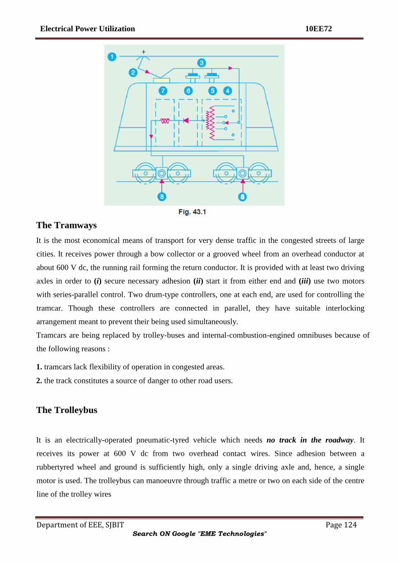
Electrical Power Utilization 10EE72
Department of EEE, SJBIT Page 124
The Tramways
It is the most economical means of transport for very dense traffic in the congested streets of large
cities. It receives power through a bow collector or a grooved wheel from an overhead conductor at
about 600 V dc, the running rail forming the return conductor. It is provided with at least two driving
axles in order to (i) secure necessary adhesion (ii) start it from either end and (iii) use two motors
with series-parallel control. Two drum-type controllers, one at each end, are used for controlling the
tramcar. Though these controllers are connected in parallel, they have suitable interlocking
arrangement meant to prevent their being used simultaneously.
Tramcars are being replaced by trolley-buses and internal-combustion-engined omnibuses because of
the following reasons :
1. tramcars lack flexibility of operation in congested areas.
2. the track constitutes a source of danger to other road users.
The Trolleybus
It is an electrically-operated pneumatic-tyred vehicle which needs no track in the roadway. It
receives its power at 600 V dc from two overhead contact wires. Since adhesion between a
rubbertyred wheel and ground is sufficiently high, only a single driving axle and, hence, a single
motor is used. The trolleybus can manoeuvre through traffic a metre or two on each side of the centre
line of the trolley wires
Search ON Google "EME Technologies"

Electrical Power Utilization 10EE72
Department of EEE, SJBIT Page 125
Overhead Equipment (OHE)
Broadly speaking, there are two systems of current collection by
a traction unit :
(i) third rail system and (ii) overhead wire system.
It has been found that current collection from overhead wire is far superior to that from the third rail.
Moreover, insulation of third rail at high voltage becomes an impracticable proposition and endangers
the safety of the working personnel.
The simplest type of OHE consists of a single contact wire of hard drawn copper or silico-bronze
supported either by bracket or an overhead span. To facilitate connection to the supports, the wire is
grooved as shown in Fig. 43.2. Because there is appreciable sag of the wire between supports, it
limits the speed of the traction unit to about 30 km/h. Hence, single contact wire system is suitable for
tramways and in complicated yards and terminal stations where speeds are low and simplicity of
layout is desirable.
For collection of current by high-speed trains, the contact (or trolley) wire has to be kept level without
any abrupt changes in its height between the supporting structures. It can be done by using the single
catenary system which consists of one catenary or messenger wire of steel with high sag and the
trolley (or contact) wire supported from messenger wire by means of droppers clipped to both wires
as shown in Fig. 43.3.
Collector Gear for OHE
The most essential requirement of a collector is that it should keep continuous contact with trolley wire
at all speeds. Three types of gear are in common use :
1. trolley collector 2. bow collector and 3. pantograph collector.
Search ON Google "EME Technologies"

Electrical Power Utilization 10EE72
Department of EEE, SJBIT Page 126
To ensure even pressure on OHE, the gear equipment must, be flexible in order to follow variations in
the sag of the contact wire. Also, reasonable precautions must be taken to prevent the collectorfrom
leaving the overhead wire at points and crossings.
The Trolley Collector
This collector is employed on tramways and trolley buses and is mounted on the roof of the vehicle.
Contact with the OH wire is made by means of either a grooved wheel or a sliding shoe carried at the
end of a light trolley pole attached to the top of the vehicle and held in contact with OH wire by
means of a spring. The pole is hinged to a swivelling base so that it may be reversed for reverse
running thereby making it unnecessary for the trolley wire to be accurately maintained abovethe
centre of the track. Trolley collectors always operate in the trailing position. The trolley collector is
suitable for low speeds upto 32 km/h beyond which there is a risk of its jumping off the OH contact
wire particularly at points and crossing.
The Bow Collector It can be used for higher speeds. As shown in Fig. 43.4, it consists of two
roofmounted trolley poles at the ends of which is placed a light metal strip (or bow) about one metre
long for currentcollection. The collection strip is purposely made of soft material (copper, aluminium
or carbon) in order that most of the wear may occur on it rather than on the trolley wire. The bow
collector also operates in the trailing position. Hence, it requires provision of either duplicate bows or
an arrangement for reversing the bow for running in the reverse direction. Bow collector is not
suitable for railway work where speeds up to 120 km/h and currents up to 3000 A are encountered. It
is so because the inertia of the bow collector is too high to ensure satisfactorycurrent collection.
Search ON Google "EME Technologies"

Electrical Power Utilization 10EE72
Department of EEE, SJBIT Page 127
The Pantograph Collector
Its function is to maintain link between overhead contact wire and power circuit of the electric
locomotive at different speeds under all wind conditions and stiffness of OHE. It means that positive
pressure has to be maintained at all times to avoid loss of contact and sparking but the pressure must
be as low as possible in order to minimize wear of OH contact wire. A ‗diamond‘ type single-pan
pantograph is shown in Fig. 43.5. It consists of a pentagonal framework of high-tensile alloy-steel
tubing. The contact portion consists of a pressed steel pan fitted with renewable copper wearing strips
which are forced against the OH contact wire by the upward action ofpantograph springs. The
pantograph can be raised or loweredfrom cabin by air cylinders.
Train Movement
The movement of trains and their energy consumption can be conveniently studied by means of
speed/time and speed/distance curves. As their names indicate, former gives speed of the train at
Search ON Google "EME Technologies"

Electrical Power Utilization 10EE72
Department of EEE, SJBIT Page 128
various times after the start of the run and the later gives speed at various distances from the starting
point. Out of the two, speed/time curve is more important because
1. its slope gives acceleration or retardation as the case may be.
2. area between it and the horizontal (i.e. time) axis represents the distance travelled.
3. energy required for propulsion can be calculated if resistance to the motion of train is known.
Typical Speed/Time Curve
Typical speed/time curve for electric trains operating on passenger services is shown in Fig. 43.8. It
may be divided into the following five parts :
1. Constant Acceleration Period (0 to t1)
It is also called notching-up or starting period because during this period, starting resistance of the
motors is gradually cut out so that the motor current (and hence, tractive effort) is maintained nearly
constant which produces constant acceleration alternatively called ‗rheostatic acceleration‘ or
‗acceleration while notching‘.
2. Acceleration on Speed Curve
(t1 to t2)
This acceleration commences after the starting resistance has been all cutout at point t1 and full
supply voltage has been applied to the motors. During this period, the motor current and torque
decrease as train speed increases. Hence, acceleration gradually decreases till torque developed by
motors exactly balances that due to resistance to the train motion. The shape of the portion AB of the
speed/time curve depends primarily on the torque/speed characteristics of the traction motors.
3. Free-running Period (t2 to t3)
The train continues to run at the speed reached at point t2. It is represented by portion BC in Fig.
43.8 and is a constant-speed period which occurs on level tracks.
4. Coasting (t3 to t4)
Power to the motors is cut off at point t3 so that the train runs under its momentum, the speed
gradually falling due to friction, windage etc. (portion CD). During this period, retardation remains
practically constant. Coasting is desirable because it utilizes some of the kinetic energy of the train
which would, otherwise, be wasted during braking. Hence, it helps to reduce the energy consumption
of the train.
Search ON Google "EME Technologies"

Electrical Power Utilization 10EE72
Department of EEE, SJBIT Page 129
5. Braking (t4 to t5)
At point t4, brakes are applied and the train is brought to rest at point t5.
It may be noted that coasting and braking are governed by train resistance and allowable retardation
respectively.
Speed/Time Curves for Different Services
Fig. 43.9 (a) is representative of city service where relative values of acceleration and retardation are
high in order to achieve moderately high average speed between stops. Due to short
Distances between stops, there is no possibility of free-running period though a short coasting period is
included to save on energy consumption.
In suburban services [Fig. 43.9 (b)], again there is no free-running period but there is comparatively
longer coasting period because of longer distances between stops. In this case also, relatively high
Search ON Google "EME Technologies"

Electrical Power Utilization 10EE72
Department of EEE, SJBIT Page 130
values of acceleration and retardation are required in order to make the service as attractive as
Possible.
For main-line service [Fig. 43.9 (c)], there are long periods of free-running at high speeds. The
accelerating and retardation periods are relatively unimportant.
Simplified Speed/Time Curve
For the purpose of comparative performance for a given service, the actual speed/time curve of Fig.
43.8 is replaced by a simplified speed/time curve which does not involve the knowledge of motor
characteristics. Such a curve has simple geometric shape so that simple mathematics can be used to
find the relation between acceleration, retardation, average speed and distance etc. The simple curve
would be fairly accurate provided it (i) retains the same acceleration and retardation and (ii) has
The same area as the actual speed/time curve. The simplified speed/time curve can have either of
the two shapes:
(i) trapezoidal shape OA1B1C of Fig. 43.10 where speed-curve running and coasting periods of the
actual speed/time curve have been replaced by a constant speed period.
(ii) Quadrilateral shape OA2B2C where the same two periods are replaced by the extensions of initial
constant acceleration and coasting periods. It is found that trapezoidal diagram OA1B1C gives
simpler relationships between the principal quantities involved in train movement and also gives
closer approximation of actual energy consumed during main-line service on level track. On the
other hand, quadrilateral diagram approximates more closely to the actual conditions in city and
suburban services.
Average and Schedule Speed
While considering train movement, the following three speeds are of importance :
1. Crest Speed. It is the maximum speed (Vm) attained by a train during the run.
2. Average Speed =distance between stops actual time of run
In this case, only running time is considered but not the stop time.
3. Schedule Speed = distance between stops actual time of run + stop time
Obviously, schedule speed can be obtained from average speed by including the duration of stops.
For a given distance between stations, higher values of acceleration and retardation will mean lesser
Search ON Google "EME Technologies"

Electrical Power Utilization 10EE72
Department of EEE, SJBIT Page 131
running time and, consequently, higher schedule speed. Similarly, for a given distance between
stations and for fixed values of acceleration and retardation, higher crest speed will result in higher
schedule speed. For the same value of average speed, increase in duration of stops decreases the
schedule speed.
SI Units in Traction Mechanics
In describing various quantities involved in the mechanics of train movement, only the latest SI
system will be used. Since SI system is an ‗absolute system‘, only absolute units will be used while
gravitational units (used hitherto) will be discarded.
1. Force. It is measured in newton (N)
2. Mass. Its unit is kilogram (kg). Commonly used bigger units is tonne (t), 1 tonne = 1000 kg
3.Energy. Its basic unit is joule (J). Other units often employed are watt-hour (Wh) and kilowatthour
(kWh).
5 J = 3.6 MJ
4. Work. Its unit is the same as that of energy.
5. Power. Its unit is watt (W) which equals 1 J/s. Other units are kilowatt (kW) and megawatt (MW).
6. Distance. Its unit is metre. Other unit often used is kilometre (km).
7. Velocity. Its absolute unit is metre per second(m/s). If velocity is given in km/h (or km.ph), it can
be easily converted into the SI unit of m/s by multiplying it with a factor of
(1000/3600) = 5/18 = 0.2778. For example, 72 km.ph =
Search ON Google "EME Technologies"

Electrical Power Utilization 10EE72
Department of EEE, SJBIT Page 132
8. Acceleration. Its unit is metre/second2 (m/s
2). If acceleration is given in km/h/s (or kmph. ps),
then it can be converted into m/s2 by simply multiplying it by the factor (1000/3600) = 5/18 = 0.2778
i.e. the same factor as for velocity.
2
Quantities Involved in Traction Mechanics
Following principal quantities are involved in train movement :
D = distance between stops
M = dead mass of the train
Me = effective mass of the train
W = dead weight of the train We =
effective weight of the train α =
accelaration during starting period β=
retardation during coasting β =
retardation during braking
Va = average speed
Vm = maximum (or crest) speed.
t = total time for the run t1 = time of acceleration t2 = time
of free running = t − (t1 + t3) t3 = time of braking
Ft = tractive effort
T = torque
Relationship Between Principal Quantities in Trapezoidal Diagram As seen from Fig. 43.11.
α = Vm /t1 or t1 = Vm /α
β = Vm /t3 or t3 = Vm /β
As we know, total distance D between the two stops is given by the area of trapezium OABC. therefore
D = area OABC
= area OAD + area ABED + area BCE
Search ON Google "EME Technologies"

Electrical Power Utilization 10EE72
Department of EEE, SJBIT Page 133
= 1 / 2 Vmt 1 + Vmt 2 +1 / 2 Vmt 3
Search ON Google "EME Technologies"

Electrical Power Utilization 10EE72
Department of EEE, SJBIT Page 134
The diagram is shown in Fig. 43.12. Let βc represent the retardation during coasting period. As
before,
Relationship Between Principal Quantities in Quadrilateral Diagram
Search ON Google "EME Technologies"

Electrical Power Utilization 10EE72
Department of EEE, SJBIT Page 135
Search ON Google "EME Technologies"

Electrical Power Utilization 10EE72
Department of EEE, SJBIT Page 136
Tractive Effort for Propulsion of a Train
The tractive effort (Ft) is the force developed by the traction unit at the rim of the driving wheels for
moving the unit itself and its train (trailing load). The tractive effort required for train propulsion on a
level track is
Ft = Fa + Fr
If gradients are involved, the above expression becomes
Ft = Fa + Fg + Fr — for ascending gradient = Fa −
Fg + Fr — for descending gradient
where Fa = force required for giving linear acceleration to the train
Fg = force required to overcome the effect of gravity
Fr = force required to overcome resistance to train motion.
(a) Value of Fa
If M is the dead (or stationary) mass of the train and a its linear acceleration, then
Fa = Ma
Since a train has rotating parts like wheels, axles, motor armatures and gearing etc., its effective (or
accelerating) mass Me is more (about 8 − 15%) than its stationary mass.
These parts have to be given angular acceleration at the same time as the whole train is accelerated in
the linear direction.
Hence, Fe = Mea
Search ON Google "EME Technologies"

Electrical Power Utilization 10EE72
Department of EEE, SJBIT Page 137
(ii) If Me is in tonne and α in km/h/s, then converting them into absolute units, we have
Fa = (1000 Me) × (1000/3600) a = 277.8 Me a newton
(b) Value of Fg
As seen from Fig. 43.13, Fg = W sin θ = Mg sin θ
In railway practice, gradient is expressed as the rise (in metres) a track distance of 100 m
and is called percentage gradient.
Therefore % G = 100/100
BC /BC
AC /AC = = 100 sin θ Substituting the value of sin θ in the above equation, we
Get Fg = Mg G/100 = 9.8 × 10⁻² MG
(i) When M is in kg, Fg = 9.8 × 10⁻² MG newton
(ii) When M is given in tonne, then
Fg = 9.8 × 10⁻² (1000 M) G = 98 MG Newton
Value of Fr
Train resistance comprises all those forces which oppose its motion. It consists of mechanical
resistance and wind resistance. Mechanical resistance itself is made up of internal and external
resistances. The internal resistance comprises friction at journals, axles, guides and buffers etc. The
external resistance consists of friction between wheels and rails and flange friction etc. Mechanical
resistance is almost independent of train speed but depends on its weight. The wind friction varies
directly as the square of the train speed. If r is specific resistance of the train i.e. resistance offered
per unit mass of the train, then Fr = M.r.
Search ON Google "EME Technologies"

Electrical Power Utilization 10EE72
Department of EEE, SJBIT Page 138
(i) If r is in newton per kg of train mass and M is the train mass in kg, then
Fr = M.r newton
(ii) If r is in newton per tonne train mass (N/t) and M is in tonne (t), then
Fr = M tonne × r = Mr newton*
Hence, expression for total tractive effort becomes
Ft = Fa ± Fg + Fr = (277.8 α Me ± 98 MG + Mr) newton
Please remember that here M is in tonne, α in km/h/s, G is in metres per 100 m of track length (i.e.
% G) and r is in newton/tonne (N/t) of train mass.
The positive sign for Fg is taken when motion is along an ascending gradient and negative sign when
motion is along a descending gradient.
Power Output from Driving Axles
If Ft is the tractive effort and ν is the train velocity, then output power = Ft × ν
(i) If Ft is in newton and ν in m/s, then output power = Ft × ν watt
(ii) If Ft is in newton and ν is in km/h , then converting ν into m/s, we have Fig. 43.13
* If r is in kg (wt) per tonne train mass and M is in tonne, then Fr = M tonne × (r × 9.8) newton/tonne =
9.8
Search ON Google "EME Technologies"

Electrical Power Utilization 10EE72
Department of EEE, SJBIT Page 139
Energy (like work) is given by the product of power and time. E =
(Ft × ν ) × t = Ft × (ν × t) = Ft × D where D is the distance
travelled in the direction of tractive effort.
Total energy output from driving axles for the run is
Energy Output from Driving Axles
Search ON Google "EME Technologies"

Electrical Power Utilization 10EE72
Department of EEE, SJBIT Page 140
E = energy during acceleration + energy during free run
As seen from Fig. 43.11
E = Ft × area OAD + Ft′ × area ABED = Ft × 1/2Vm t1 + Ft′ × 1/2Vm t2 where Ft is the tractive effort
during accelerating period and Ft′ that during free running period. Incidentally, Ft will consist of all
the three components given in Art. 43.37 whereas Ft′ will consist of (98 MG + Mr) provided there is
an ascending gradient.
Specific Energy Output
It is the energy output of the driving wheel expressed in watt-hour (Wh) per tonne-km (t-km) of the
train. It can be found by first converting the energy output into Wh and then dividing it by the mass
of the train in tonne and route distance in km.
Hence, unit of specific energy output generally used in railway work is : Wh/tonne-km (Wh/t-km).
Evaluation of Specific Energy Output
We will first calculate the total energy output of the driving axles and then divide it by train mass in
tonne and route length in km to find the specific energy output. It will be presumed that :
(i) there is a gradient of G throughout the run and
(ii) power remains ON upto the end of free run in the case of trapezoidal curve and upto the
accelerating period in the case of quadrilateral curve
Now, output of the driving axles is used for the following purposes :
1. for accelerating the train 2. for overcoming the gradient
3. for overcoming train resistance.
(a) Energy required for train acceleration (Ea)
As seen from trapezoidal diagram
Search ON Google "EME Technologies"
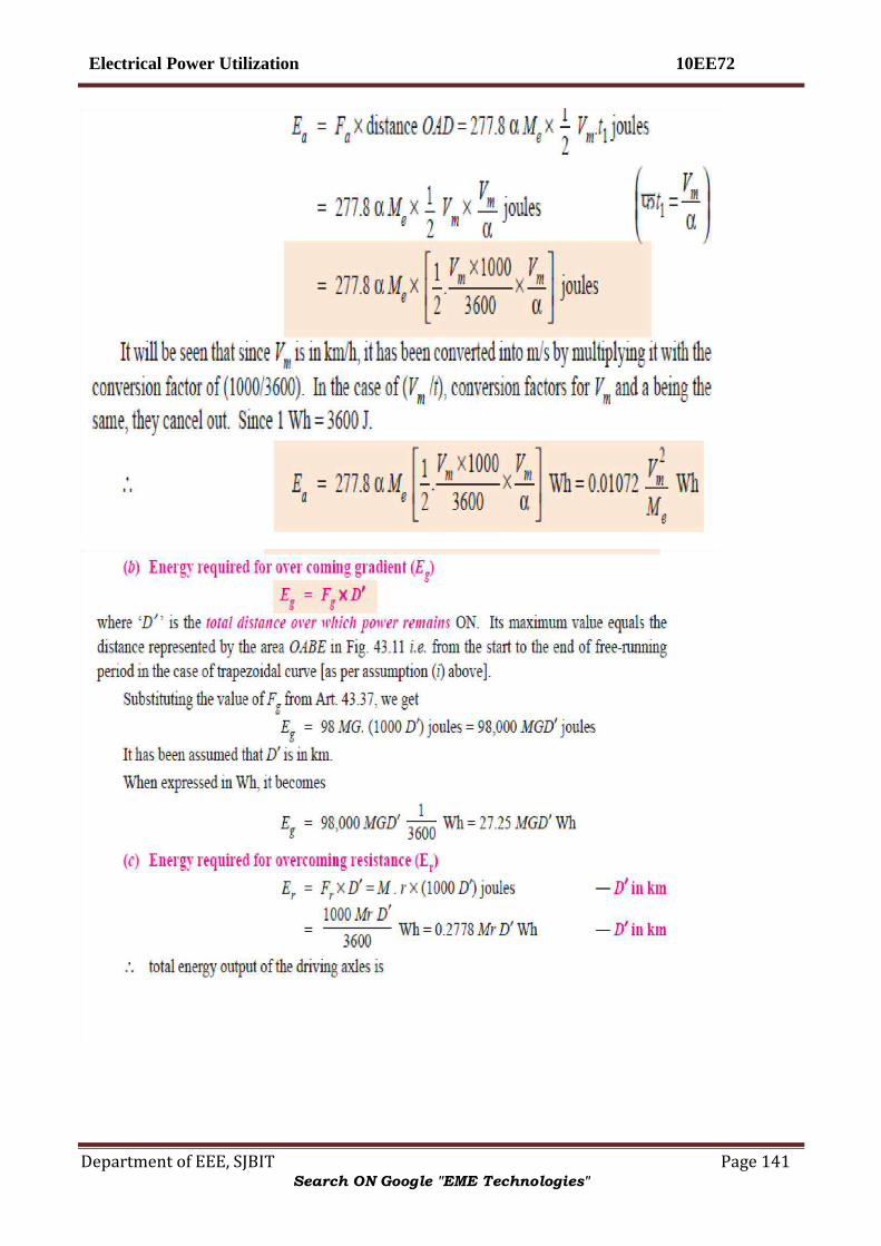
Electrical Power Utilization 10EE72
Department of EEE, SJBIT Page 141
Search ON Google "EME Technologies"

Electrical Power Utilization 10EE72
Department of EEE, SJBIT Page 142
Search ON Google "EME Technologies"

Electrical Power Utilization 10EE72
Department of EEE, SJBIT Page 143
Energy Consumption
It equals the total energy input to the traction motors from the supply. It is usually expressed in Wh
which equals 3600 J. It can be found by dividing the energy output of the driving wheels with the
combined efficiency of transmission gear and motor.
Specific Energy Consumption
It is the energy consumed (in Wh) per tonne mass of the train per km length of the run.
Specific energy consumption,
Search ON Google "EME Technologies"

Electrical Power Utilization 10EE72
Department of EEE, SJBIT Page 144
The specific energy consumption of a train running at a given schedule speed is
influenced by
1. Distance between stops 2. Acceleration 3. Retardation 4. Maximum speed 5. Type of
train and equipment 6. Track configuration.
Adhesive Weight
It is given by the total weight carried on the driving wheels. Its value is Wa = x W, where W is dead
weight and x is a fraction varying from 0.6 to 0.8.
Coefficient of Adhesion
Adhesion between two bodies is due to interlocking of the irregularities of their surfaces in contact.
The adhesive weight of a train is equal to the total weight to be carried on the driving
Search ON Google "EME Technologies"

Electrical Power Utilization 10EE72
Department of EEE, SJBIT Page 145
It has been found that tractive effort can be increased by increasing the motor torque but only Up to a
certain point. Beyond this point, any increase in motor torque does not increase the tractive effort but
merely causes the driving wheels to slip. It is seen from the above relation that for increasing Ft, it is
not enough to increase the kW rating of the traction motors alone but the weight on the driving
wheels has also to be increased.
Adhesion also plays an important role in braking. If braking effort exceeds the adhesive weight of the
vehicle, skidding takes place.
Mechanism of Train Movement
The essentials of driving mechanism in an electric vehicle are illustrated in Fig. 43.14. The armature
of the driving motor has a pinion which meshes with the gear wheel keyed to the axle of the driving
wheel. In this way, motor torque is transferred to the wheel through the gear.
Let, T = torque exerted by the motor
Search ON Google "EME Technologies"

Electrical Power Utilization 10EE72
Department of EEE, SJBIT Page 146
F1 = tractive effort at the pinion
Ft = tractive effort at the wheel
γ = gear ratio
Here, d1, d2 = diameters of the pinion and gear wheel respectively
D = diameter of the driving wheel
η = efficiency of power transmission from the motor to driving axle
Now, T = F1 × d1/2 or F1 = 2T/d1
Tractive effort transferred to the driving wheel is
For obtaining motion of the train without slipping, Ft ≤ μa Wa where μa is the coefficient of adhesion
(Art. 43.45) and Wa is the adhesive weight.
Control of D.C. Motors
The starting current of motor is limited to its normal rated current by starter during starting. At the
instant of switching on the motor, back e.m.f. Eb = 0 therefore Supply voltage = V = IR + Voltage
drop across Rs.
At any other instant during starting
V = IR + Voltage across Rs + Eb
At the end of accelerating period, when total Rs is cut-off V = Eb + IR
If T is the time in sec. for starting and neglecting IR drop, total energy supplied = V.I.T. watt-sec
Search ON Google "EME Technologies"
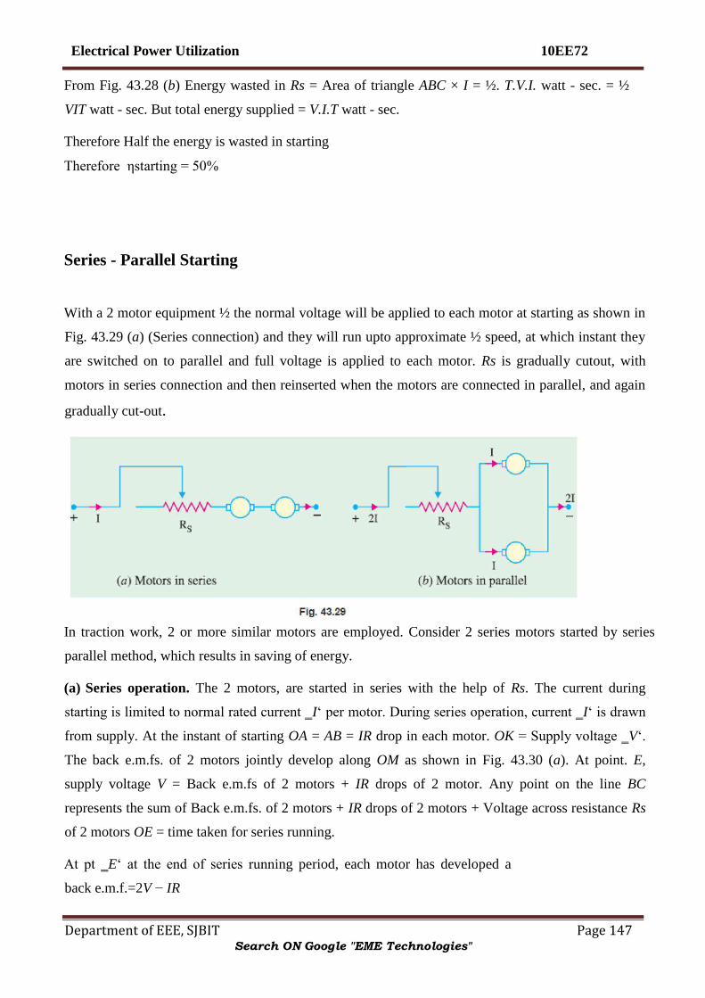
Electrical Power Utilization 10EE72
Department of EEE, SJBIT Page 147
From Fig. 43.28 (b) Energy wasted in Rs = Area of triangle ABC × I = ½. T.V.I. watt - sec. = ½
VIT watt - sec. But total energy supplied = V.I.T watt - sec.
Therefore Half the energy is wasted in starting
Therefore ηstarting = 50%
Series - Parallel Starting
With a 2 motor equipment ½ the normal voltage will be applied to each motor at starting as shown in
Fig. 43.29 (a) (Series connection) and they will run upto approximate ½ speed, at which instant they
are switched on to parallel and full voltage is applied to each motor. Rs is gradually cutout, with
motors in series connection and then reinserted when the motors are connected in parallel, and again
gradually cut-out.
In traction work, 2 or more similar motors are employed. Consider 2 series motors started by series
parallel method, which results in saving of energy.
(a) Series operation. The 2 motors, are started in series with the help of Rs. The current during
starting is limited to normal rated current ‗I‘ per motor. During series operation, current ‗I‘ is drawn
from supply. At the instant of starting OA = AB = IR drop in each motor. OK = Supply voltage ‗V‘.
The back e.m.fs. of 2 motors jointly develop along OM as shown in Fig. 43.30 (a). At point. E,
supply voltage V = Back e.m.fs of 2 motors + IR drops of 2 motor. Any point on the line BC
represents the sum of Back e.m.fs. of 2 motors + IR drops of 2 motors + Voltage across resistance Rs
of 2 motors OE = time taken for series running.
At pt ‗E‘ at the end of series running period, each motor has developed a
back e.m.f.=2V − IR
Search ON Google "EME Technologies"

Electrical Power Utilization 10EE72
Department of EEE, SJBIT Page 148
EL = ED – LD
(b) Parallel operation. The motors are switched on in parallel at the instant ‗E‘, with Rs reinserted
as shown in Fig. 43.29 (b). Current drawn is 2I from supply. Back e.m.f. across each motor = EL. So
the back e.m.f. now develops along LG. At point ‗H‘ when the motors are in full parallel, (Rs = 0 and
both the motors are running at rated speed)
Supply voltage = V = HF = HG + GF= Normal Back e.m.f. of each motor + IR drop in each motor.
To find ts, tp and η of starting The values of time ts during which the motors remain in series and tp
during which they are in parallel can be determined from Fig. 43.30 (a), (c). From Fig. 43.30 (a),
Search ON Google "EME Technologies"

Electrical Power Utilization 10EE72
Department of EEE, SJBIT Page 149
starting, neglect IR drop in armature circuit.
This modifies Fig. 43.30 (a) to Fig. 43.30 (c). ‗D‘ is midpoint of CE and back e.m.f. develops along
DF in parallel combination. KC = CF i.e. time for series combination = time for parallel combination
triangles OLE and OGH are similar
Search ON Google "EME Technologies"

Electrical Power Utilization 10EE72
Department of EEE, SJBIT Page 150
i.e. ts = tp = t and average starting current = I per motor.
But total energy supplied
Series Parallel Control by Shunt Transition Method
The various stages involved in this method of series – parallel control are shown in Fig. 43.31 In steps
1, 2, 3, 4 the motors are in series and are accelerated by cutting out the Rs in steps. In step 4, motors
are in full series. During transition from series to parallel, Rs is reinserted in circuit– step 5. One of
the motors is bypassed -step 6 and disconnected from main circuit – step 7. It is then connected in
parallel with other motor -step 8, giving 1st parallel position. Rs is again cut-out in steps completely
and the motors are placed in full parallel.
= I V t + 2 I V t ( Series) (Parallel ) = 3 V I t
Search ON Google "EME Technologies"

Electrical Power Utilization 10EE72
Department of EEE, SJBIT Page 151
The main difficulty with series parallel control is to obtain a satisfactory method of transition from
series to parallel without interrupting the torque or allowing any heavy rushes of current.
In shunt transition method, one motor is short circuited and the total torque is reduced by about 50%
during transition period, causing a noticeable jerk in the motion of vehicle. The Bridge transition is
more complicated, but the resistances which are connected in parallel with or ‗bridged‘ across the
motors are of such a value that current through the motors is not altered in magnitude and the total
torque is therefore held constant and hence it is normally used for railways.
Search ON Google "EME Technologies"

Electrical Power Utilization 10EE72
Department of EEE, SJBIT Page 152
So in this method it is seen that, both motors remain in circuit through-out the transition. Thus the jerks
will not be experienced if this method is employed.
Series Parallel Control by Bridge Transition
(a) At starting, motors are in series with Rs i.e. link P in position = AA′
(b) Motors in full series with link P in position = BB Rs in the circuit)
The motor and Rs are connected in the form of Wheatstone Bridge. Initially motors are in series with
full Rs as shown in Fig. 43.32 (a). A and A heads. In position
BB b), with no Rs present in the circuit.
Search ON Google "EME Technologies"

Electrical Power Utilization 10EE72
Department of EEE, SJBIT Page 153
In transition step the Rs is reinserted.
In Ist parallel step, link P is removed and motors are connected in parallel with full Rs as shown in
Fig. 43.32 (c). Advantage of this method is that the normal acceleration torque is available from both
the motors, through - out starting period. Therefore acceleration is smoother, without any jerks, which
is very much desirable for traction motors.
Braking in Traction
Both electrical and mechanical braking is used. Mechanical braking provides holding torque. Electric
Braking reduces wear on mechanical brakes, provides higher retardation, thus bringing a vehicle
quickly to rest. Different types of electrical braking used in traction are discussed.
Rheostatic Braking
(a) Equalizer Connection (b) Cross Connection
(a) Equalizer Connection
For traction work, where 2 or more motors are employed, these are connected in parallel for braking,
because series connection would produce too high voltage. K.E. of the vehicle is utilized in driving
the machines as generators, which is dissipated in braking resistance in the form of heat.
To ensure that the 2 machines share the load equally, an equalizer connection is used as shown in Fig.
43.33 (a). If it is not used, the machine whose acceleration builts-up first would send a current
through the 2nd machine in opposite direction, causing it to excite with reverse voltage. So that the 2
machines would be short circuited on themselves. The current would be dangerously high. Equalizer
prevents such conditions. Hence Equalizer connection is important during braking in traction.
(b) Cross Connection
Search ON Google "EME Technologies"

Electrical Power Utilization 10EE72
Department of EEE, SJBIT Page 154
In cross connection the field of machine 2 is connected in series with armature of machine 1 and the
field of machine 1 is connected in series with armature of machine 2 as shown in Fig. 43.33 (b).
Suppose the voltage of machine 1 is greater than that of 2. So it will send greater current through field
of machine 2, causing it to excite to higher voltage. At the same time machine 1 excitation is low,
because of lower voltage of machine 2. Hence machine 2 will produce more voltage and machine 1
voltage will be reduced. Thus automatic compensation is provided and the 2 machines operate
satisfactorily.
Because of cross - connection during braking of traction motors, current in any of the motor will not go
to a very high value.
Regenerative Braking with D.C. Motors
In order to achieve the regenerative braking, it is essential that (i) the voltage generated by the
machine should exceed the supply voltage and (ii) the voltage should bez kept at this value,
irrespective of machine speed. Fig. 43.34 (a) shows the case of 4 series motors connected in parallel
during normal running i.e. motoring.
One method of connection during regenerative barking, is to arrange the machines as shunt machines,
with series fields of 3 machines connected across the supply in series with suitable resistance. One of
the field winding is still kept in series across the 4 parallel armatures as shown in figure 43.34 (b).
The machine acts as a compound generator. (with slight differential compounding) Such an
arrangement is quiet stable; any change in line voltage produces a change in excitation which
produces corresponding change in e.m.f. of motors, so that inherent compensation is provided e.g. let
the line voltage tends to increase beyond the e.m.f. of generators. The increased voltage across the
shunt circuit increases the excitation thereby increasing the generated voltage. Vice-versa is also true.
The arrangement is therefore self compensating.
Search ON Google "EME Technologies"

Electrical Power Utilization 10EE72
Department of EEE, SJBIT Page 155
D.C. series motor can‘t be used for regenerative braking without modification for obvious reasons.
During regeneration current through armature reverses; and excitation has to be maintained. Hence
field connection must be reversed.
Expected Questions
1. Find the schedule speed of an electric train for a run of 1.5 km if the ratio of its maximum to
average speed is 1.25. It has a braking retardation of 3.6 km/h/s, acceleration of 1.8 km/h/s and stop
time of 21 second. Assume trapezoidal speed/time curve.
2. A train runs between two stations 1.6 km apart at an average speed of 36 km/h. If the maximum
speed is to be limited to 72 km/h, acceleration to 2.7 km/h/s, coasting retardation to 0.18 km/h/s and
braking retardation to 3.2 km/h/s, compute the duration of acceleration, coasting and braking periods.
Assume a simplified speed/time curve.
Search ON Google "EME Technologies"

Electrical Power Utilization 10EE72
Department of EEE, SJBIT Page 156
3. The peripheral speed of a railway traction motor cannot be allowed to exceed 44 m/s. If gear ratio
is 18/75, motor armature diameter 42 cm and wheel diameter 91 cm, calculate the limiting value of
the train speed.
4 . A 250-tonne motor coach driven by four motors takes 20 seconds to attain a speed of 42 km/h,
starting from rest on an ascending gradient of 1 in 80. The gear ratio is 3.5, gear efficiency 92%,
wheel diameter 92 cm train resistance 40 N/t and rotational inertia 10 percent of the dead weight.
Find the torque developed by each motor.
5. A 250-tonne motor coach having 4 motors, each developing a torque of 8000 N-m during
acceleration, starts from rest. If up-gradient is 30 in 1000, gear ratio 3.5, gear transmission efficiency
90%, wheel diameter 90 cm, train resistance 50 N/t, rotational inertia effect 10%, compute the time
taken by the coach to attain a speed of 80 km/h.
If supply voltage is 3000 V and motor efficiency 85%, calculate the current taken during the
acceleration period.
6. A goods train weighing 500 tonne is to be hauled by a locomotive up an ascending gradient of 2%
with an acceleration of 1 km/h/s. If coefficient of adhesion is 0.25, train resistance 40 N/t and effect
of rotational inertia 10%, find the weight of locomotive and number of axles if load is not to increase
beyond 21 tonne/axle.
7. An electric locomotive weighing 100 tonne can just accelerate a train of 500 tonne (trailing
weight) with an acceleration of 1 km/h/s on an up-gradient of 0.1%. Train resistance is 45 N/t and
rotational inertia is 10%. If this locomotive is helped by another locomotive of weight 120 tonne, find
:
(i) the trailing weight that can now be hauled up the same gradient under the same conditions. (ii) the
maximum gradient, if the trailing hauled load remains unchanged. Assume adhesive weight expressed
as percentage of total dead weight as 0.8 for both locomotives.
8. The average distance between stops on a level section of a railway is 1.25 km. Motor-coach train
weighing 200 tonne has a schedule speed of 30 km/h, the duration of stops being
30 seconds. The acceleration is 1.9 km/h/s and the braking retardation is 3.2 km/h/s. Train resistance
to traction is 45 N/t. Allowance for rotational inertia is 10%. Calculate the specific energy output in
Wh/t-km. Assume a trapezoidal speed/time curve.
9. A 350-tonne electric train runs up an ascending gradient of 1% with the following speed/time
curves :
Search ON Google "EME Technologies"

Electrical Power Utilization 10EE72
Department of EEE, SJBIT Page 157
uniform acceleration of 1.6 km/h/s for 25 seconds. constant speed for 50 seconds 3. coasting for 30
seconds. braking at 2.56 km/h/s to rest.
Compute the specific energy consumption if train resistance is 50 N/t, effect of rotational inertia 10%,
overall efficiency of transmission gear and motor, 75%.
10. An ore-carrying train weighing 5000 tonne is to be hauled down a gradient of 1 : 50 at a maximum
speed of 30 km/h and started on a level track at an acceleration of 0.29 km/h/s. How many
locomotives, each weighing 75 tonne, will have to be employed ? Train resistance during starting =
29.4 N/t, Train resistance at 30 km/h = 49 N/t Coefficient of adhesion = 0.3, Rotational inertia =
10%
11. A 200-tonne electric train runs according to the following quadrilateral speed/ time curve:
1. uniform acceleration from rest at 2 km/h/s for 30 seconds
2. coasting for 50 seconds
3. duration of braking : 15 seconds
If up-gradient is = 1%, train resistance = 40 N/t, rotational inertia effect = 10%, duration of stops = 15 s
and overall efficiency of gear and motor = 75%, find
(i) schedule speed (ii) specific energy consumption (iii) how will the value of specific energy
consumption change if there is a down-gradient of 1% rather than the up-gradient ?
12. An electric train has an average speed of 45 kmph on a level track between stops 1500 m apart. It
is accelerated at 1.8 kmphps and is braked at 3 kmphps. Draw the speed – time curve for the run.
13. A train has schedule speed of 60 km per hour between the stops which are 9 km apart. Determine
the crest speed over the run, assuming trapezoidal speed – time curve. The train accelerates at 3
kmphps and retards at 4.5 kmphps. Duration of stops is 75 seconds.
14. An electric train is to have acceleration and braking retardation of 1.2 km/ hour/sec and 4.8
km/hour/sec respectively. If the ratio of maximum to average speed is 1.6 and time for stops 35
seconds, find schedule speed for a run of 3 km. Assume simplified trapezoidal speedtime curve. 15
An electric train has a schedule speed of 25 kmph between stations 800 m apart. The duration of stop
is 20 seconds, the maximum speed is 20 percent higher than the average running speed and the
braking retardation is 3 kmphps. Calculate the rate of acceleration required to operate this service.
16. A suburban electric train has a maximum speed of 80 kmph. The schedule speed including a
station stop of 35 seconds is 50 kmph. If the acceleration is 1.5 kmphps, find the value of retardation
when the average distance between stops is 5 km.
Search ON Google "EME Technologies"

Electrical Power Utilization 10EE72
Department of EEE, SJBIT Page 158
17. A train is required to run between two stations 1.6 km apart at the average speed of 40 kmph. The
run is to be made to a simplified quadrilateral speed-time curve. If the maximum speed is to be
limited to 64 kmph, acceleration to 2.0 kmphps and coasting and braking retardation to 0.16 kmphps
and 3.2 kmphps respectively, determine the duration of acceleration, coasting and braking periods.
18. The following figures give the magnetization curve of d.c. series motor when working as a
separately excited generator at 600 rpm.:
Field Current (amperes) : 20 40 60 80
E.M.F. (volts) : 215 381 485 550
The total resistance of the motor is 0.8 ohm. Deduce the speed – torque curve for this motor when
operating at a constant voltage of 600 volts.
Search ON Google "EME Technologies"

Electrical Power Utilization 10EE72
Department of EEE, SJBIT Page 159
UNIT-8
INTRODUCTION TO ELECTRIC AND HYBRID VEHICLES:
Advantages of Electric Drive
Almost all modern industrial and commercial undertakings employ electric drive in preference to
mechanical drive because it possesses the following advantages :
1. It is simple in construction and has less maintenance cost
2. Its speed control is easy and smooth
3. It is neat, clean and free from any smoke or flue gases
4. It can be installed at any desired convenient place thus affording more flexibility in the layout
5. It can be remotely controlled
6. Being compact, it requires less space
7. It can be started immediately without any loss of time
8. It has comparatively longer life.
However, electric drive system has two inherent disadvantages:
1. It comes to stop as soon as there is failure of electric supply and
2. It cannot be used at far off places which are not served by electric supply.
However, the above two disadvantages can be overcome by installing diesel-driven dc generators and
turbine-driven 3-phase alternators which can be used either in the absence of or on the failure of
normal electric supply.
Classification of Electric Drives
Electric drives may be grouped into three categories : group drive, individual drive and multimotor
drive.
In group drive, a single motor drives a number of machines through belts from a common shaft.
It is also called line shaft drive. In the case of an indvidual drive, each machine is driven by its own
separate motor with the help of gears, pulley etc. In multi-motor drives separate motors are provided
for actuating different parts of the driven mechanism. For example, in travelling cranes, three motors
are used: one for hoisting, another for long travel motion and the third for cross travel motion.
Search ON Google "EME Technologies"

Electrical Power Utilization 10EE72
Department of EEE, SJBIT Page 160
Multimotor drives are commonly used in paper mills, rolling mills, rotary printing presses and metal
working machines etc.
Each type of electric drive has its own advantages and disadvantages. The group drive has following
advantages :
1. It leads to saving in initial cost because one 150-kW motor costs much less than ten 15-kW
motors needed for driving 10 separate machines.
2. Since all ten motors will seldom be required to work simultaneously, a single motor of even
100kW will be sufficient to drive the main shaft. This diversity in load reduces the initial cost still
further.
3. Since a single large motor will always run at full-load, it will have higher efficiency and power
factor in case it is an induction motor.
4. Group drive can be used with advantage in those industrial processes where there is a sequence of
continuity in the operation and where it is desirable to stop these processes simultaneously as in a
flour mill.
However, group drive is seldom used these days due to the following disadvantages:
1. Any fault in the driving motor renders all the driven equipment idle. Hence, this system is
unreliable.
2. If all the machines driven by the line shaft do not work together, the main motor runs at reduced
load. Consequently, it runs with low efficiency and with poor power factor 3. Considerable amount
of power is lost in the energy transmitting mechanism.
4. Flexibility of layout of different machines is lost since they have to be so located as to suit the
position of the line shaft.
5. The use of line shaft, pulleys and belts etc. makes the drive look quite untidy and less safe to operate.
6. It cannot be used where constant speed is required as in paper and textile industry.
7. Noise level at the worksite is quite high.
Advantages of Individual Drive
It has the following advantages:
1. Since each machine is driven by a separate motor, it can be run and stopped as desired.
2. Machines not required can be shut down and also replaced with a minimum of dislocation.
Search ON Google "EME Technologies"

Electrical Power Utilization 10EE72
Department of EEE, SJBIT Page 161
3. There is flexibility in the installation of different machines.
4. In the case of motor fault, only its connected machine will stop whereas others will continue working
undisturbed.
5. The absence of belts and line shafts greatly reduces the risk of accidents to the operating personnel.
6. Ach operator has full control of the machine which can be quickly stopped if an accident occurs.
7. Maintenance of line shafts, bearings, pulleys and belts etc. is eliminated. Similarly there is no danger
of oil falling on articles being manufactured–something very important in textile industry. The only
disadvantage of individual drive is its initial high cost (Ex 44.1). However, the use of individual
drives and multimotor drives has led to the introduction of automation in production processes
which, apart from increasing the productivity of various undertakings, has increased the reliability
and safety of operation.
Selection of a Motor
The selection of a driving motor depends primarily on the conditions under which it has to operate and
the type of load it has to handle. Main guiding factors for such a selection are as follows :
(a) Electrical characteristics
1. Starting characteristics 2. Running characteristics
3. Speed control 4. Braking
(b) Mechanical considerations
1. Type of enclosure 2. Type of bearings
3. Method of power transmission 4. Type of cooling
5. Noise level
(c) Size and rating of motors
1. Requirement for continuous, intermittent or variable load cycle
2. Overload capacity
(d) Cost
1. Capital cost 2. Running cost
In addition to the above factors, one has to take into consideration the type of current available
whether alternating or direct. However, the basic problem is one of matching the mechanical output
of the motor with the load requirement i.e. to select a motor with the correct speed/torque
characteristics as demanded by the load. In fact, the complete selection process requires the analysis
and synthesis of not only the load and the proposed motor but the complete drive assembly and the
control equipment which may include rectification or frequency changing.
Search ON Google "EME Technologies"

Electrical Power Utilization 10EE72
Department of EEE, SJBIT Page 162
Types of Enclosures
The main function of an enclosure is to provide protection not only to the working personnel but also
to the motor itself against the harmful ingress of dirt, abrasive dust, vapours and liquids and solid
foreign bodies such as a spanner or screw driver etc. At the same time, it should not adversely affect
the proper cooling of the motor. Hence, different types of enclosures are used for different motors
depending upon the environmental conditions. Some of the commonly used motor enclosures are as
under:
1. Open Type. In this case, the machine is open at both ends with its rotor being supported on
pedestal bearings or end brackets. There is free ventilation since the stator and rotor ends are in free
contact with the surrounding air. Such, machines are housed in a separate neat and clean room.
This type of enclosure is used for large machines such as d.c. motors and generators.
2. Screen Protected Type. In this case, the enclosure has large openings for free ventilation.
However, these openings are fitted with screen covers which safeguard against accidental contacts
and rats entering the machine but afford no protection from dirt, dust and falling water. Screen
protected type motors are installed where dry and neat conditions prevail without any gases or
fumes.
3. Drip Proof Type. This enclosure is used in very damp conditions. i.e. for pumping sets. Since
motor openings are protected by over-hanging cowls, vertically falling water and dust are not able
to enter the machine.
4. Splash-proof Type. In such machines, the ventilating openings are so designed that liquid or dust
particles at an angle between vertical and 100° from it cannot enter the machine. Such type of
motors can be safely used in rain.
5. Totally Enclosed (TE) Type. In this case, the motor is completely enclosed and no openings are
left for ventilation. All the heat generated due to losses is dissipated from the outer surface which is
finned to increase the cooling area. Such motors are used for dusty atmosphere i.e. sawmills,
coalhandling plants and stone-crushing quarries etc.
6. Totally-enclosed Fan-cooled
(TEFC) Type. In this case, a fan is mounted on the shaft external to the totally enclosed casing and
air is blown over the ribbed outer surfaces of the stator and endshields (Fig. 44.1). Such motors are
commonly used in flour mills, cement works and sawmills etc. They require little maintenance apart
Search ON Google "EME Technologies"
Electrical Power Utilization 10EE72
Department of EEE, SJBIT Page 163
from lubrication and are capable of giving years of useful service without any interruption of
production.
7. Pipe-ventilated Type. Such an enclosure is used for very dusty surroundings. The motor is totally
enclosed but is cooled by neat and clean air brought through a separate pipe from outside the
dustladen area. The extra cost of the piping is offset by the use of a smaller size motor on account
of better cooling.
8. Flame-proof (FLP) Type. Such motors are employed in atmospheres which contain inflammable
gases and vapours i.e. in coal mines and chemical plants. They are totally enclosed but their
enclosures are so constructed that any explosion within the motor due to any spark does not ignite
the gases outside. The maximum operating temperature at the surface of the motor is much less
than the ignition temperature of the surrounding gases.
Bearings
These are used for supporting the rotating parts of the machines and are of two types :
1. Ball or roller bearings 2. Sleeve or bush bearings
(a) Ball Bearings
Upto about 75kW motors, ball bearings are preferred to other bearings because of their following
advantages :
1. They have low friction loss
2. They occupy less space
3. They require less maintenance
4. Their use allows much smaller air-gap between the stator and rotor of an induction motor
5. Their life is long.
Their main disadvantages are with regard to cost and noise particularly at high motor speeds.
(b) Sleeve Bearings
These are in the form of self-aligning pourous bronze bushes for fractional kW motors and in the
Search ON Google "EME Technologies"

Electrical Power Utilization 10EE72
Department of EEE, SJBIT Page 164
form of journal bearings for larger motors. Since they run very silently,
they are fitted on super-silent motors used for driving fans and lifts in offices or other applications
where noise must be reduced to the absolute minimum.
Transmission of Power
There are many ways of transmitting mechanical power developed by a motor to the driven machine.
1. Direct Drive. In this case, motor is coupled directly to the driven machine with the help of solid
or flexible coupling. Flexible coupling helps in protecting the motor from sudden jerks. Direct drive
is nearly 100% efficient and requires minimum space but is used only when speed of the driven
machine equals the motor speed.
2. Belt Drive. Flat belts are extensively used for line-shaft drives and can transmit a maximum
power of about 250 kW. Where possible, the minimum distance between the pulley centres should be
4 times the diameter of the larger pulley with a maximum ratio between pulley diameters of 6 : 1. The
power transmitted by a flat belt increases in proportion to its width and varies greatly with its quality
and thickness. There is a slip of 3 to 4 per cent in the belt drive.
3. Rope Drive. In this drive, a number of ropes are run in V-grooves over the pulleys. It has
negligible slip and is used when the power to be transmitted is beyond the scope of belt drive. 4.
Chain Drive. Though somewhat more expensive, it is more efficient and is capable of transmitting
larger amounts of power. is noiseless, slipless and smooth in operation.
5. Gear Drive. It is used when a high-speed motor is to drive a low-speed machine. The coupling
between the two is through a suitable ratio gear box. In fact motors for low-speed drives are
manufactured with the reduction gear incorporated in the unit itself. Fig. 44.2 shows such a unit
Search ON Google "EME Technologies"

Electrical Power Utilization 10EE72
Department of EEE, SJBIT Page 165
consisting of a flange motor bolted to a high-efficiency gear box which is usually equipped with feet,
the motor being overhung.
Noise
The noise produced by a motor could be magnetic noise, wind age noise and mechanical noise. Noise
level must be kept to the minimum in order to avoid fatigue to the workers in a workshop. Similarly,
motors used for domestic and hospital appliances and in offices and theatres must be almost
noiseless. Transmission of noise from the building where the motor is installed to another building
can be reduced if motor foundation is flexible i.e. has rubber pads and springs.
Motors for Different Industrial Drives
1. D.C. Series Motor. Since it has high starting torque and variable speed, it is used for heavy duty
applications such as electric locomotives, steel rolling mills, hoists, lifts and cranes.
2. D.C. Shunt Motor. It has medium starting torque and a nearly constant speed. Hence, it is used
for driving constant-speed line shafts, lathes, vacuum cleaners, wood-working machines, laundry
washing machines, elevators, conveyors, grinders and small printing presses etc.
3. Cumulative Compound Motor. It is a varying-speed motor with high starting torque and is used
for driving compressors, variable-head centrifugal pumps, rotary presses, circular saws, shearing
machines, elevators and continuous conveyors etc.
Search ON Google "EME Technologies"

Electrical Power Utilization 10EE72
Department of EEE, SJBIT Page 166
4. Three-phase Synchronous Motor. Because its speed remains constant under varying loads, it is
used for driving continuously- operating equipment at constant speed such as ammonia and air
compressors, motor-generator sets, continuous rolling mills, paper and cement industries.
5. Squirrel Cage Induction Motor. This motor is quite simple but rugged and possesses high
overload capacity. It has a nearly constant speed and poor starting torque. Hence, it is used for low
and medium power drives where speed control is not required as for water pumps, tube wells, lathes,
drills, grinders, polishers, wood planers, fans, blowers, laundry washing machines and compressors
etc.
6. Double Squirrel Cage Motor. It has high starting torque, large overload capacity and a nearly
constant speed. Hence, it is used for driving loads which require high starting torque such as
compressor pumps, reciprocating pumps, large refrigerators, crushers, boring mills, textile machinery,
cranes, punches and lathes etc.
7. Slip-ring Induction Motor. It has high starting torque and large overload capacity. Its speed can
be changed up to 50% of its normal speed. Hence, it is used for those industrial drives which require
high starting torque and speed control such as lifts, pumps, winding machines, printing presses, line
shafts, elevators and compressors etc.
8. Single-phase Synchronous Motor. Because of its constant speed, it is used in teleprinters,
clocks, all kinds of timing devices, recording instruments, sound recording and reproducing systems.
9. Single-phase Series Motor. It possesses high starting torque and its speed can be controlled over
a wide range. It is used for driving small domestic appliances like refrigerators and vacuum cleaners
etc.
10. Repulsion Motor. It has high starting torque and is capable of wide speed control. Moreover, it
has high speed at high loads. Hence, it is used for drives which require large starting torque and
adjustable but constant speed as in coil winding machines.
11. Capacitor-start Induction-run Motor. It has fairly constant speed and moderately high starting
torque. Speed control is not possible. It is used for compressors, refrigerators and small portable
hoists.
12. Capacitor-start-and-run Motor. Its operating characteristics are similar to the above motor
except that it has better power factor and higher efficiency. Hence, it is used for drives requiring quiet
operations.
Advantages of Electrical Braking Over Mechanical Braking
Search ON Google "EME Technologies"

Electrical Power Utilization 10EE72
Department of EEE, SJBIT Page 167
1. In mechanical braking; due to excessive wear on brake drum, liner etc. it needs frequent and costly
replacement. This is not needed in electrical braking and so electrical braking is more economical than
mechanical braking.
2. Due to wear and tear of brake liner frequent adjustments are needed thereby making the
maintenance costly.
3. Mechanical braking produces metal dust, which can damage bearings. Electrical braking has no
such problems.
4. If mechanical brakes are not correctly adjusted it may result in shock loading of machine or
machine parts in case of lift, trains which may result in discomfort to the occupants.
5. Electrical braking is smooth. Heavy duty hydraulic motor for high torque and low speeds
6. In mechanical braking the heat is produced at brake liner or brake drum, which may be a source of
failure of the brake. In electric braking the heat is produced at convenient place, which in no way is
harmful to a braking system.
7. In regenerative braking electrical energy can be returned back to the supply which is not possible in
mechanical braking.
8. Noise produced is very high in mechanical braking. Only disadvantage in electrical braking is that
it is ineffective in applying holding torque.
Types of Electric Braking
There are three types of electric braking as applicable to electric motors in addition to eddy current
braking. These have already been discussed briefly in Art. 44.7.
1. Plugging or reverse-current braking.
2. Rheostatic or dynamic braking.
3. Regenerative braking.
In many cases, provision of an arrangement for stopping a motor and its driven load is as important as
starting it. For example, a planning machine must be quickly stopped at the end of its stroke in order
to achieve a high rate of production. In other cases, rapid stops are essential for preventing any danger
to operator or damage to the product being manufactured. Similarly, in the case of lifts and hoists,
effective braking must be provided for their proper functioning.
Plugging Applied to D.C. Motors
Search ON Google "EME Technologies"

Electrical Power Utilization 10EE72
Department of EEE, SJBIT Page 168
As discussed earlier in Art. 42.7, in this case, armature connections are reversed whereas field
winding connections remains unchanged. With reversed armature connections, the motor develops a
torque in the opposite direction. When speed reduces to zero, motor will accelerate in the opposite
direction. Hence, the arrangement is made to disconnect the motor from the supply as soon as it
comes to rest. Fig. 44.3 shows running and reversed connections for shunt motors whereas Fig. 44.4
shows similar conditions for series motors.
Since with reversed connection, V and Eb are in the same direction, voltage across the armature is
almost double of its normal value. In order to avoid excessive current through the armature,
additional resistance R is connected in series with armature.
This method of braking is wasteful because in addition to wasting kinetic energy of the moving parts, it
draws additional energy from the supply during braking.
Search ON Google "EME Technologies"

Electrical Power Utilization 10EE72
Department of EEE, SJBIT Page 169
Energy Saving in Regenerative Braking
We will now compute the amount of energy recuperated between any two points on a level track
during which regenerative braking is employed. The amount of energy thus recovered and then
returned to the supply lines depends on :
(i) initial and final velocities of the train during braking (ii)
efficiency of the system and (iii) train resistance.
Suppose regenerative braking is applied when train velocity is V1 km/h and ceases when it is V2 km/h.
If Me tonne is the effective mass of the train, then
Search ON Google "EME Technologies"

Electrical Power Utilization 10EE72
Department of EEE, SJBIT Page 170
Search ON Google "EME Technologies"

Electrical Power Utilization 10EE72
Department of EEE, SJBIT Page 171
Expected Questions
1.What are the advantages of Electric drives.
2.What are Advantages of Electrical Braking Over Mechanical Braking
3.What do you mean by Regenerative Breaking
4. How energy is converted to hybrid vehicles through motors
5. What do you mean by hybrid vehicles?
6.How hybrid vehicles are nature friendly
7.What are motors to be selected for interconnection with hybrid vehicles
Search ON Google "EME Technologies"


