
1
Elastic Solutions for Eccentrically Loaded, Slender, Precast and Prestressed Concrete Spandrel Beams
Bülent Mercan, Graduate Research Assistant, University of Minnesota, Minneapolis
Arturo E. Schultz, Professor of Civil Engineering, University of Minnesota, Minneapolis
Henryk K. Stolarski, Professor of Civil Engineering, University of Minnesota, Minneapolis
Rafael, A. Magaña, President, Precast Engineering Systems, Tampa, Florida
Mathew J. Lorig, Graduate Student, Department of Physics, Univ. of California – Santa Barbara
Abstract:
Spandrel beams in precast concrete buildings are widely used to support double-tee
deck beams. Spandrel beams of deep cross sections, resisting eccentric loads from
double-tee beams, can be susceptible to excessive lateral deformations and serviceability
failures before reaching their strength limits. In this paper, exact and approximate
analytical solutions are derived from second order elastic analysis to estimate maximum
lateral deflections in laterally restrained and unrestrained spandrel beams under eccentric
and uniformly distributed loads. Continuous lateral support is provided at the elevation
of the floor deck in restrained spandrel beams. An equivalent loading method is
proposed to obtain the approximate analytical solutions, in which the differential
equations of equilibrium governing the problem are simplified by modifying the actual
loads in spandrel beams. Numerical solutions are also obtained from three-dimensional
finite element analyses and their results are found to be in close agreement with those of
analytical solutions.
CE Database subject headings:
Precast concrete; Prestressed concrete; Lateral displacement; Eccentric loads; Analytical
techniques; Numerical analysis.

2
Introduction
Precast and prestressed concrete spandrel beams (Fig. 1) are usually used in the
perimeter of precast concrete buildings and support precast double-tees serving as deck
beams. There are three common types of spandrel beams depending upon the manner in
which the double tees are supported; spot-corbel spandrels (Fig. 1.a) with discontinuous
ledges, L-shaped spandrels with continuous ledges (Fig. 1.b) and pocket spandrels (Fig.
1.c) with rectangular cutouts. The spandrel beam resists eccentric loading which stems
from vertical double-tee loads acting through the horizontal offsets provided by corbels
or cut-outs. The spandrel beam is supported simply at its soffits by the column corbels.
Torsional constraint, which is an additional connection of the spandrel to the columns
prevents twisting of the spandrel ends, is achieved by means of threaded inserts (i.e., tie-
back bolts) at two elevations above the column corbels. The load bearing spandrel beam
is also laterally restrained along the mid-height level of its web by spandrel-to-double-tee
connections (i.e., deck ties).
Previous research
There are several publications on the study of the interaction of and design for
combined shear, torsion and bending in reinforced or prestressed concrete flexural
members (Raths 1984; Klein 1986; Lucier et al. 2007). However, the vast majority of
this work has focused on stress and strength design considerations, and mention is seldom
made of lateral deflection and serviceability of flexural members. Only a limited amount
of research on the stability of tall, slender ‘reinforced’ concrete beams is found in the

3
technical literature, including experimental studies from the 1950s and 1960s conducted
in the U.S. (Hansel and Winter 1959; Sant and Bletzacker 1961); Marshall 1969) and
more recent ones (Revathi and Mennon 2006; Revathi and Mennon 2007; Kalkan 2009).
However, all of these studies aimed at exploring the lateral instability of concentrically
loaded reinforced concrete beams. Historically, lateral deflections have often been
ignored in the design of precast and prestressed concrete spandrel beams, as well as many
other concrete members, since they are assumed to be too stocky for lateral deflections to
be more critical than stress or force considerations. However, due to technological
improvements and industry needs, longer (up to 60 ft) and thinner (as little as 8 in.)
spandrel beams are being introduced to the market. Based on this current trend, lateral
deflections for slender spandrel beams need to be evaluated.
In order to find the analytical solution for maximum lateral deflections in spandrel
beams, the governing differential equations of equilibrium need to be established first.
To this end, the differential equations for the lateral-torsional buckling problem in
concentrically loaded elastic beams, which are homogenous, isotropic and prismatic, can
be used. The solution reported by Timoshenko in 1936 (Timoshenko and Gere 1961) is
well known and referenced in many textbooks on steel design (e.g., Bleich 1952; Gaylord
et al. 1992; Salmon and Johnson 1996; Galambos et al. 1996). The differential equations
of equilibrium can be easily extended to include torsional effects and solved to obtain
find expressions for lateral deflection and angle of twist.
Linearly elastic material behavior can be assumed only for prestressed concrete, since
the actual response of pure concrete is highly nonlinear. Prestress in concrete usually

4
eliminates or significantly reduces tensile stresses in the members under service loads,
thus providing resistance to cracking. Concrete also exhibits nonlinear stress-strain
relationship for compressive stresses greater than about one-half of its compressive
strength. However, a reduced modulus of elasticity Er can be used to represent the
concrete behavior for deflection calculations. Such an approach is often used in practice,
for example, Sant and Bletzacker (1961) recommend a value for the reduced modulus Er
equal to 0.687Ec to account for nonlinearity in the stress-strain relation for concrete in
compression in tall, slender reinforced concrete beams.
In this work, second-order elastic analyses were conducted to evaluate lateral
deflections and angle of twist in restrained and unrestrained rectangular beams subjected
to eccentric vertical loading. Finding the closed-form solution to the differential
equations governing this problem turned out impossible. Therefore, an equivalent
loading procedure was proposed, in which governing differential equations were
significantly simplified and solved to obtain approximate expressions for deflection and
angle-of-twist. Finally, analytical results were compared with those obtained from the
nonlinear finite element analyses of the spandrel beams.
Lateral restraints with deck-tie plates
Load bearing spandrel beams typically have deck-ties along its span length to provide
a lateral connection between spandrel and double tees. However, some practicing
engineers do not rely on the deck-ties as providing sufficient lateral supports for spandrel
beams. There are valid reasons for this; first, the ties are not proportioned to meet a

5
design goal; second, deck-tie stress/force not computed; third, the influence of cyclic
loading not considered on fatigue life; fourth, protection from corrosion not provided; so
the reliability of these connections is not known to provide a lateral connection between
spandrel and double-tees.
A typical deck-tie connection, as illustrated in Fig. 2, is built on site by simply
welding a steel plate to two other steel elements (e.g., plates or angles) which were
already embedded into the spandrel web and the double-tee flange in the precast plant.
Deck-ties connecting the spandrel web to the double-tees are often placed near the neutral
axis elevation of the spandrel section, in which case they do not restrain twisting
deformations in a significant manner. However, once these connections are established,
the pattern of lateral deflections changes since the beam cannot deflect laterally at the
level of the double tee connections as long as the deck-tie welds are intact. Yet, the
welding of the deck-tie plates does not take place immediately upon placing the double
tees. So, it is somewhat risky to rely on these connections while the structure is being
erected. Moreover, high-cycle fatigue (from vehicle loading), low-cycle fatigue (from
extreme loading), stresses from volumetric effects (temperature, creep and shrinkage of
concrete) and corrosion raise further doubts on the reliability of the deck-tie connections.
Therefore, the lateral deflection of a spandrel beam should be investigated for two
idealized cases (Fig. 3); (a) unrestrained beam and (b) restrained beam, in which the
lateral deformations are prevented by deck-ties at the mid-height level along the span
length.

6
In extreme cases of large twisting angles, the supports of the double tees can be lost,
leading to the collapse of the structure. Fig. 3 shows the deformed shapes of spandrel
webs of restrained and unrestrained beams. If the lateral deflection at the bottom of the
restrained beam is larger than the overlap distance at the bearing pad (Fig. 2), the double-
tee beams will slip out of the spandrel ledge and collapse. There is no such collapse
mechanism for laterally unrestrained beams since lateral deformations always tend to
move toward the double-tees. Still, unrestrained beams can experience large lateral
deflections before reaching their design capacities and fail to satisfy serviceability
requirements.
Laterally unrestrained and concentrically loaded beams
In general, slender elastic beams with deep and narrow rectangular cross sections do
not experience lateral deflections when concentric loads (i.e., without lateral eccentricity
producing torsion) are applied. At a critical load (buckling load), slender beams suddenly
undergo large lateral deformations, which is called lateral and torsional buckling. This
type of instability likely occurs when the flexural rigidity of a beam in the plane of
bending is significantly larger than that in the out-of-plane direction. The theory of
lateral-torsional buckling of slender beams under concentric loads is well known and
extensively investigated for steel beams (e.g., Bleich 1952; Gaylord et al. 1992; Salmon
and Johnson 1996; Galambos et al. 1996). Before looking into the behavior of
eccentrically loaded beams, a short discussion on concentrically loaded beams is
necessary for several reasons; (a) differential equations of equilibrium derived for a

7
concentrically loaded beam can be easily extended to the case of an eccentrically loaded
beams (b) the use of the buckling load parameter in the derivations will significantly
simplify the analytical expressions, and (c) the influence of eccentric loading on the
lateral response will be more meaningful when it is compared with the response of a
concentrically loaded beam.
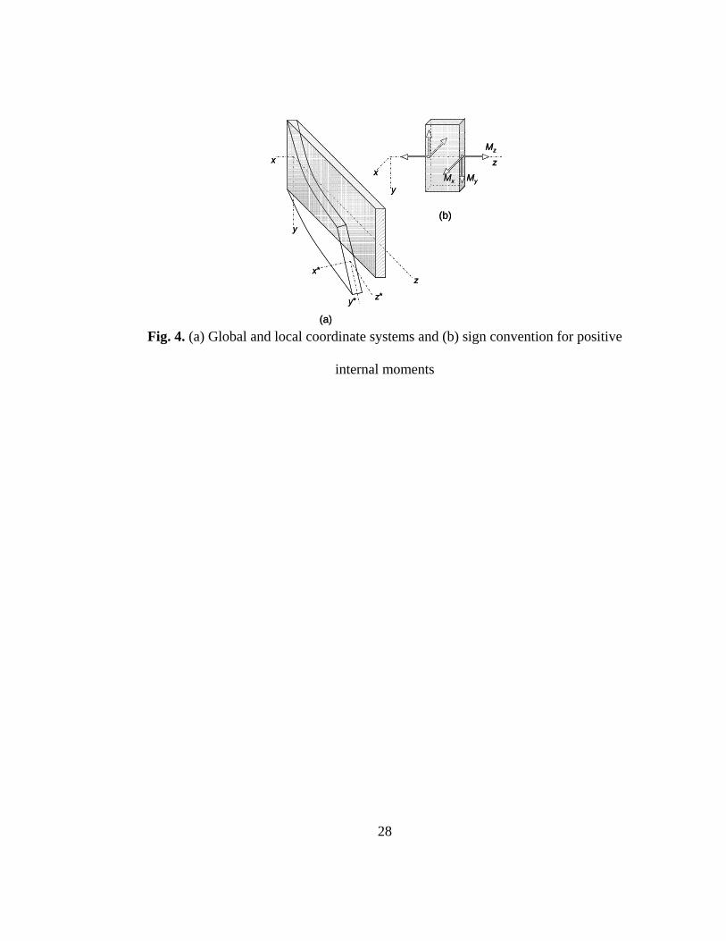
A deep and narrow rectangular beam subjected to strong-axis bending-moment
couples Mo at the ends suddenly becomes unstable, deforms laterally and twists, as
depicted in Fig. 4.a, when the moment Mo attains a critical value Mcr. In order to
determine the critical buckling moment, governing equilibrium equations are established
for a slightly deformed shape (or buckled shape) of the beam. The smallest value of
bending moment couples Mo that maintains the equilibrium of the beam in such buckled
shape is equal to the critical value of buckling moment Mcr.
The global and local coordinate axes, x-y-z and x*-y*-z*, respectively, are selected, as
shown in Fig. 4.a. The vertical deformation of the centroid of the beam cross section v,
the lateral deformation u, and the angle of twist φ are defined in the buckled shape of the
beam, as illustrated in Fig. 5. The angle of twist φ is assumed to be positive when the
cross section rotates from the x- to the y-axis, or when the rotation vector defined using
‘right-hand rule’ is parallel to the positive direction of z. It should be noted that the
deformations, u, v, and φ, are very small and higher-order terms will be neglected. The
governing differential equations of equilibrium are to be established in the buckled shape
of the beam. Therefore, the curvatures of the centerline of the beam in y*z*- and x*z*-
planes and the moments Mx*, My*, and Mz*, are required. The positive directions of
8
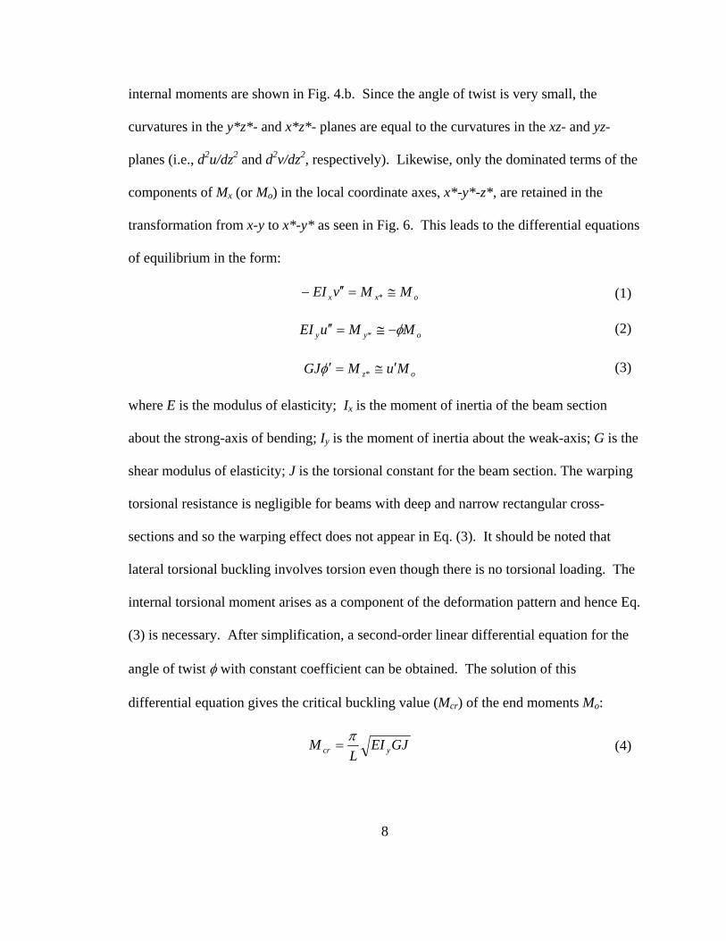
internal moments are shown in Fig. 4.b. Since the angle of twist is very small, the
curvatures in the y*z*- and x*z*- planes are equal to the curvatures in the xz- and yz-
planes (i.e., d2u/dz2 and d2v/dz2, respectively). Likewise, only the dominated terms of the
components of Mx (or Mo) in the local coordinate axes, x*-y*-z*, are retained in the
transformation from x-y to x*-y* as seen in Fig. 6. This leads to the differential equations
of equilibrium in the form:
oxx MMvEI ≅=′′− * (1)
oyy MMuEI φ−≅=′′ * (2)
oz MuMGJ ′≅=′ *φ (3)
where E is the modulus of elasticity; Ix is the moment of inertia of the beam section
about the strong-axis of bending; Iy is the moment of inertia about the weak-axis; G is the
shear modulus of elasticity; J is the torsional constant for the beam section. The warping
torsional resistance is negligible for beams with deep and narrow rectangular cross-
sections and so the warping effect does not appear in Eq. (3). It should be noted that
lateral torsional buckling involves torsion even though there is no torsional loading. The
internal torsional moment arises as a component of the deformation pattern and hence Eq.
(3) is necessary. After simplification, a second-order linear differential equation for the
angle of twist φ with constant coefficient can be obtained. The solution of this
differential equation gives the critical buckling value (Mcr) of the end moments Mo:
GJEIL
M ycrπ
= (4)

9
Eq. (4) is derived for the loading case of equal and opposite end moments. For cases
with moment gradient, the critical moment can be adjusted using the bending coefficient
Cb, based on approximate expressions 0- 0. The coefficient Cb is equal to unity for
uniform bending (i.e., equal end moments) and 1.13 for uniformly distributed vertical
loads. Incorporating the Cb factor, the critical moment given by Eq. (4) becomes:
GJEIL
CM ybcrπ
= (5)
Laterally unrestrained and eccentrically loaded beams
In order to investigate the influence of eccentric loading on the lateral deflection of
spandrel beams, a simplified structural system (Fig. 7.a), in which a slender beam with
rectangular cross section is subjected to uniformly distributed load q with an eccentricity
e, is taken into account. The bending moment Mx has a parabolic distribution along the
span length, Mx=(qL2/2)[q/L-(q/L)2]. Due to the torsionally fixed supports, as well as the
symmetry of the beam and loading pattern, the torsional reactions at the ends (MT=qeL/2)
are equal, but in opposite directions. The distribution of internal torsion along the length
of beam is a linear function of z, Mz = MT(1-2z/L), with the left end of the beam
undergoing positive torsion.
Timoshenko’s solution does not explicitly address beams with torsional loading (i.e.,
lateral eccentricity), but the formulation of the governing differential equations can be
easily extended to include torsional loading (Schultz and Magaña 2000). The
components of the torsion along the x*, y*, and z* axes in the deformed position must be

10
included in the three moment equilibrium equations, Eqs (1), (2), and (3). As illustrated
in Fig. 7.b, a positive beam slope du/dz in the horizontal x-z plane produces a torsional
component Mzdu/dz in the local x* axis which is negative according to the sign
convention described in Fig. 4.b. Thus, positive torsion Mz acting through a positive
horizontal slope du/dz generates a negative moment contribution for x-axis euilibrium in
Eq. (1). Similarly, in Fig. 7.b, a positive beam slope dv/dz in the vertical y-z plane
produces a torsional component MTdv/dz in the local y* axis which opposes positive
bending as indicated in Fig. 4. Thus, positive torsion Mz acting through a positive vertical
slope dv/dz produces a negative moment contribution for y-axis equilibrium in Eq. (2).
zxx MuMvEI ′−=′′− (6)
zxy MvMuEI ′−−=′′ φ (7)
zx MMuGJ +′=′φ (8)
The case of a laterally unrestrained beam under eccentric loading introduces a
parabolic function of length z for bending moment Mx and a linear function of z for
torsion Mz, which makes coefficients of Eqs (6), (7), and (8) variable. As a result, the
closed-form solution of Eqs (6), (7), and (8) becomes difficult, if not impossible. Still, an
approximate closed-form solution can be found if the actual loading in the beam is
replaced with an equivalent loading, shown in Fig. 8. The actual loading case consists of
uniformly distributed load q acting over an eccentricity e. For the equivalent loading
approach, fictitious but approximately equivalent effects are defined, as seen in Fig. 8.
The actual load is replaced by the end moments Mo (=qoL2/8) and a uniformly distributed
torque mo modified by the load parameter qo, (qo=q/Cb where Cb is the bending

11
coefficient mentioned above). Obviously, the moment Mo has been assumed so as to
obtain the same maximum bending moment for both the actual and equivalent loading
conditions. Such equivalent loads yield a differential equation of equilibrium with
constant coefficient (as presented later) and provide an approximate closed-form solution.
The accuracy of the equivalent loading approach will be discussed in detail later by
comparing numerical results from actual loading with analytical results obtained from the
equivalent loading.
Differential equations can be simplified by neglecting the last terms of Eqs (6) and (7),
(-Mzdu/dz and -Mzdv/dz), due to the fact that the torsional moment Mz is generally very
small relative to Mo. Under this condition, for the case of laterally unrestrained and
eccentrically loaded beam (with the equivalent loading), the differential equations of
equilibrium are:
ox MvEI =′′− (9)
oy MuEI φ−=′′ (10)
⎟⎠⎞
⎜⎝⎛ −+′=′
LzLeq
MuGJ oo 21
2φ (11)
Solving Eq. (10) for φ and substituting its derivative dφ /dz into Eq. (11), we find
( )GJEI
MLzLeq
GJEIM
uuy
oo
y
o ⎟⎠⎞
⎜⎝⎛ −−=′+′′′ 21
2
2
(12)
Introducing (of Eq. (4))
LMMLq
MGJEIL
Mcr
oooycr
παπ
=== and,8
,2
(13)
Eq. (12) is transformed into

12
Lz
Le
Leuu 222 84 ααα +−=′+′′′
(14)
The solution of equation (14) gives the following formula for the lateral deflection u as a
function of the position z along the beam.
⎟⎟⎠
⎞⎜⎜⎝
⎛−+++= z
Lz
LeAzAzAzu
2
321 4)sin()cos()( αα (15)
The constants, A1, A2 and A3, are obtained using the following boundary conditions;
u(0)= φ (0)=0 and u’(L/2)=0.
Considering that
⎟⎠⎞
⎜⎝⎛ −+=′′−= 2
22
21 8)sin()cos(
LezAzA
MEI
uMEI
o
y
o
y ααααφ (16)
the constants, A1, A2 and A3, turn out to be:
22122
18,080,0,0
LeA
LeA
MEI
zo
y
ααφ ==⎟
⎠⎞
⎜⎝⎛ −+== (17)
223322
8,0008,0,0LeAA
Leuz
αα−==+++== (18)
)2/tan(8,00)2/cos()2/sin(8,0,2 222222 L
LeALAL
LeuLz α
ααααα
α==++−=′= (19)
From Eqs. (15), (16), (17), (18), and (19) the following formula for u and φ are obtained.
⎟⎟⎠
⎞⎜⎜⎝
⎛−+−+= z
Lz
Le
LezL
Lez
Leu
2
222222 48)sin()2/tan(8)cos(8α
ααα
αα
(20)
( )1)sin()2/tan()cos(82 −+= zLz
Le
MEI
o
y αααφ (21)

13
To get the maximum lateral deflection parameter um for this laterally unrestrained beam,
we substitute z=L/2 in Eq. (20), obtaining
⎟⎟⎠
⎞⎜⎜⎝
⎛−−= 18
)2/cos(18
2222 LLLeum ααα
(22)
Introducing the parameters in equations (13), to Eq. (22) for the maximum lateral
deflection um of the centroidal section at midspan of the beam can be written as
⎪⎭
⎪⎬⎫
⎪⎩
⎪⎨⎧
−⎥⎦
⎤⎢⎣
⎡−⎟⎟
⎠
⎞⎜⎜⎝
⎛=⎟
⎠⎞
⎜⎝⎛= 11
2sec
)/(/8
2 2
2
cr
o
crom M
MMM
eLuu ππ (23)
while the maximum angle of twist φm is
⎥⎦
⎤⎢⎣
⎡−⎟⎟
⎠
⎞⎜⎜⎝
⎛=⎟
⎠⎞
⎜⎝⎛= 1
2sec
/12
2 cr
o
crom M
MMML
eL πφφ (24)
Later, the above expressions will be used to reveal the relationship between the
maximum lateral deflection and the bending moment for various values of eccentricity.
Laterally restrained and eccentrically loaded beams
Here we assume that several deck-ties located along the length of a spandrel beam
provide a nearly continuous support sufficient to prevent lateral displacements at the mid-
height level of the spandrel as long as the connections remain intact. However, the beam
is free to rotate around the horizontal line of the deck-ties. In the case of a deep beam
subjected to eccentric loading, such twisting deformation may result in large lateral
displacements at the top and bottom of the cross section of the beam, which may put the

14
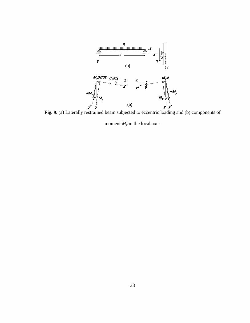
safety of the structure at risk. Therefore, the maximum lateral deflection in a laterally
restrained beam under eccentric load (Fig. 9.a) is to be analyzed herein.
Unlike unrestrained beams, laterally restrained beams are subjected to horizontal
reaction forces at their lateral supports, yielding a weak axis bending moment My along
their span length. The moment My is unknown at the beginning of the analysis and varies
along the length of the beam. To obtain the governing differential equations of
equilibrium for this case, we first determine the components of the bending moment
vector My in the x*, y*, and z* coordinate system, as shown in Fig. 9.b, and then add
them to the differential equations of equilibrium Eqs (6), (7), and (8), previously derived
for the case of laterally unrestrained beams.
Thus differential equations of equilibrium for restrained beams are
φyzxx MuMMvEI +′−=′′− (25)
yzxy MvMMuEI +′−−=′′ φ (26)
vMMuMGJ yzx ′++′=′φ (27)
An approximate solution of this problem can be obtained by neglecting higher order
terms; Mzdu/dz, Myφ, Mzdv/dz, and Mydv/dz. In general, My and Mz are relatively small
comparing to Mx (or Mo) and their products with the slopes (i.e., du/dz and dv/dz) or the
angle of twist φ are even smaller. While these assumptions are introduced to obtain an
approximate closed form solution (to be later verified by the finite element analyses),
their introduction can be also rationalized on the physical ground. Namely, for laterally
restrained beams, lateral curvature and thus lateral bending moment are small. Also, the
moment Mx is dominant in comparison with Mz (which has been assumed earlier).

15
Further simplification can be made using the equivalent loading approach, which was
previously described for the case of unrestrained beams. Under these assumptions, the
differential equations become
φyox MMvEI +=′′− (28)
φoy MM = (29)
⎟⎠⎞
⎜⎝⎛ −=′
LzLeq
GJ o 212
φ (30)
It needs to be emphasized that My is an unknown function, which defines the variation of
the weak axis bending due to the reaction forces at the lateral supports. Furthermore, the
lateral deflection u disappears in these equations since it is fixed by deck-ties close to the
centroidal axis of the beam (true only if deck ties are at the centroidal elevation).
Integrating Eq. (30) with respect to z, and considering that φ=0 at z=0, we find
⎟⎟⎠
⎞⎜⎜⎝
⎛−=
Lzz
GJLeqo
2
2φ
(31)
The angle of twist attains its maximum value φm at the mid-span of the beam and is equal
to
GJLeqo
m 8
2
=φ (32)
With the notation specified in equations (13), one has
GJEI
LMeM
GJeM y
cr
oom
πφ == (33)
Assuming G=0.4E, J=hb3/3 and Iy=hb3/12 in the equation above, we find the approximate
value of the maximum angle of twist

16
cr
om M
MLe5.2=φ
(34)
Bending moment-lateral deflection curves
In the above discussion of laterally unrestrained beams, the maximum lateral
deflection um of the centroidal line of the beam was calculated. However, due to twisting
(see Fig. 3), the lateral deflection um is smaller than the deflection at the top of the section
umt and larger than that at the bottom umb. For serviceability considerations, it is
necessary to find the magnitude of the maximum deflection. Considering that
deformation of the analyzed beam involves twist, the lateral deflections vary linearly
along the depth of the beam. To describe this variation, the top and bottom deflections
are computed
22huuandhuu mmmbmmmt φφ −=+= (35)
where h is the height of the cross section. The maximum lateral deflection occurs at the
top of the mid-span section and its magnitude can be calculated using the following
equation, derived by substituting Eqs. (23) and (24) in Eq. (35).
⎪⎪
⎭
⎪⎪
⎬
⎫
⎪⎪
⎩
⎪⎪
⎨
⎧
−⎥⎦
⎤⎢⎣
⎡+⎥
⎦
⎤⎢⎣
⎡−⎟⎟
⎠
⎞⎜⎜⎝
⎛
=+= 1/
//81
2sec
2
2
cro
crocr
o
mmmt MMLh
MMMM
ehuu
ππ
φ (36)
However, in the case of laterally restrained beams, lateral deflections of the beam at its
mid-height level are not permitted. Therefore, due to twisting of the beam, as illustrated

17
in Fig. 3, lateral deflections are developed at the top and bottom of the section (i.e., umt
and umb). These deflections are equal, but in opposite directions and computed as
follows:
22huandhu mmbmmt φφ −== (37)
Using Eq. (34), derived for the angle of twist at the mid-span of the beam, the maximum
lateral deflections at the top and bottom of the cross section of a restrained beam are:
⎟⎟⎠
⎞⎜⎜⎝
⎛−=−=
Lh
MM
ehucr
ommb 25.1
2φ (38)
Using Eqs. (36) and (38) with the height-to-length ratio h/L=0.11, relationships
between maximum lateral deflections (umt and umb) and bending moment Mo for laterally
unrestrained and restrained beams subjected to eccentric loading are shown in Fig. 10 for
various values of eccentricity ratios e/L equal to 0.002, 0.007, and 0.015. Positive
deflections umt occur for laterally unrestrained beams, which means that beams moves
toward the double-tees. These curves, on the positive region of the graph, illustrate the
high sensitivity of the unrestrained beam to the eccentricity of the load, with lateral
deflection, umt, growing in an unbounded manner as the critical value for bending
moment Mo is approached. However, this critical moment Mcr, which corresponds to the
horizontal asymptote for the family of curves shown in Fig. 10, is the same for all values
of e/L. Torsional effect due to the eccentricity, in fact, serves merely to perturb the
relationship between Mo and umt in the same manner as would an initial imperfection (i.e.,
out-of-straightness). Thus, the torsional effect serves only to increase the lateral

18
deflection of the beam before it buckles (i.e., when it is still in a theoretically stable
configuration).
In Fig. 10, negative deflections umb are noted for the laterally restrained beams. The
bottom of the mid-span section of the beam moves outward. The relationships between
lateral deflections umb and bending moment Mo are shown for different eccentricity ratios.
With an increase of the eccentricity, magnitudes of lateral deflections increase for
restrained beams, but still remain much smaller than those for unrestrained beams for the
same Mo/Mcr ratio. Based on Eq. (38), it can also be concluded that lateral deflections are
proportional to both the height-to-length ratio h/L and the eccentricity e.
In order to compare lateral deflections at the centroid and top of the mid-span section
of a laterally unrestrained beam, bending moment-lateral deflection curves for various
eccentricity parameters were plotted in Fig. 11, using Equations (23) and (36),
respectively. The figure shows that the centroid of the section undergoes slightly smaller
lateral deflections than the top of the section due to the twisting of the beam. Even tough
the lateral distance between these two points at the section increases with an increase of
eccentricity, twisting of the beam contributes slightly to the maximum lateral deflection.
The effect of slenderness ratio h/L on the maximum lateral deflection (at the top) in a
laterally unrestrained beam is also investigated. The slenderness ratio h/L of beams i
assumed to range from 0.08 to 0.24. Fig. 12 shows bending moment-lateral deflections
curves for various eccentricity parameters (e/L=0.002, 0.007 and 0.015). Bending
moment-lateral deflection curves for beams with small values of eccentricity parameters
(i.e., e/L=0.002) are not significantly affected by different slenderness ratios. The lateral
19
response of an unrestrained beam is more sensitive to its slenderness ratio if the
eccentricity increases (i.e., e/L=0.015).
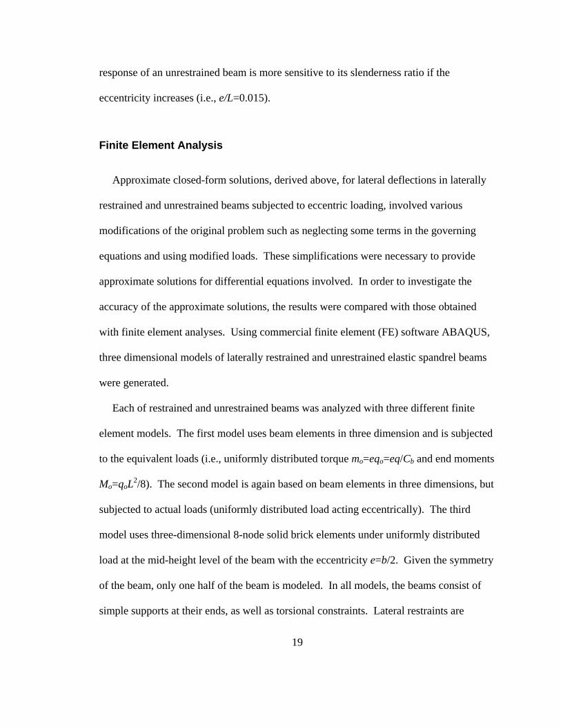
Finite Element Analysis
Approximate closed-form solutions, derived above, for lateral deflections in laterally
restrained and unrestrained beams subjected to eccentric loading, involved various
modifications of the original problem such as neglecting some terms in the governing
equations and using modified loads. These simplifications were necessary to provide
approximate solutions for differential equations involved. In order to investigate the
accuracy of the approximate solutions, the results were compared with those obtained
with finite element analyses. Using commercial finite element (FE) software ABAQUS,
three dimensional models of laterally restrained and unrestrained elastic spandrel beams
were generated.
Each of restrained and unrestrained beams was analyzed with three different finite
element models. The first model uses beam elements in three dimension and is subjected
to the equivalent loads (i.e., uniformly distributed torque mo=eqo=eq/Cb and end moments
Mo=qoL2/8). The second model is again based on beam elements in three dimensions, but
subjected to actual loads (uniformly distributed load acting eccentrically). The third
model uses three-dimensional 8-node solid brick elements under uniformly distributed
load at the mid-height level of the beam with the eccentricity e=b/2. Given the symmetry
of the beam, only one half of the beam is modeled. In all models, the beams consist of
simple supports at their ends, as well as torsional constraints. Lateral restraints are
20
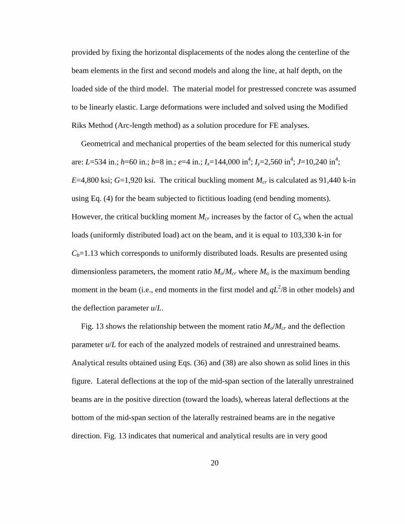
provided by fixing the horizontal displacements of the nodes along the centerline of the
beam elements in the first and second models and along the line, at half depth, on the
loaded side of the third model. The material model for prestressed concrete was assumed
to be linearly elastic. Large deformations were included and solved using the Modified
Riks Method (Arc-length method) as a solution procedure for FE analyses.
Geometrical and mechanical properties of the beam selected for this numerical study
are: L=534 in.; h=60 in.; b=8 in.; e=4 in.; Ix=144,000 in4; Iy=2,560 in4; J=10,240 in4;
E=4,800 ksi; G=1,920 ksi. The critical buckling moment Mcr is calculated as 91,440 k-in
using Eq. (4) for the beam subjected to fictitious loading (end bending moments).
However, the critical buckling moment Mcr increases by the factor of Cb when the actual
loads (uniformly distributed load) act on the beam, and it is equal to 103,330 k-in for
Cb=1.13 which corresponds to uniformly distributed loads. Results are presented using
dimensionless parameters, the moment ratio Mo/Mcr where Mo is the maximum bending
moment in the beam (i.e., end moments in the first model and qL2/8 in other models) and
the deflection parameter u/L.
Fig. 13 shows the relationship between the moment ratio Mo/Mcr and the deflection
parameter u/L for each of the analyzed models of restrained and unrestrained beams.
Analytical results obtained using Eqs. (36) and (38) are also shown as solid lines in this
figure. Lateral deflections at the top of the mid-span section of the laterally unrestrained
beams are in the positive direction (toward the loads), whereas lateral deflections at the
bottom of the mid-span section of the laterally restrained beams are in the negative
direction. Fig. 13 indicates that numerical and analytical results are in very good

21
agreement for both restrained and unrestrained beams. In fact the analytical results
closely match the numerical results from the model under the equivalent loading, which
proves that neglecting higher order terms when finding the analytical solutions does not
lead to significant error. For laterally unrestrained beams, Fig. 13 also shows that there is
a minor discrepancy between actual and equivalent loading cases. Consequently, it is
seen that the equivalent loading is a powerful tool to estimate the lateral deflections in
laterally restrained and unrestrained slender beams under uniformly distributed eccentric
loads. It should be noted that the e/L and h/L ratios for the beam studied here were 0.007
and 0.11, respectively, and similar numerical and analytical responses were observed for
other e/L and h/L ratios, not shown here for brevity.
Conclusions
Slender, precast and prestressed concrete spandrel beams under eccentric loading are
susceptible to large lateral deformations and possible serviceability failure before
reaching their stability or strength limits. Depending of the strength and reliability of
deck-tie connections, spandrel beams were classified as; (a) an unrestrained beam, which
is free to deform laterally, and (b) a restrained beam, which was assumed to have a
continuous lateral support along the centroidal line of the beam. In this study,
approximate analytical solutions for maximum lateral deflections in laterally restrained
and unrestrained rectangular beams under eccentric loading were derived exploring a
simplified version of second-order elastic analysis.

22
To obtain a simple closed-form approximate solution for the governing differential
equations of the problem, the equivalent loading approach is proposed, in which the
eccentric load (actual load) is replaced with end bending moments and uniform torque
(equivalent loads), properly calculated. After finding the maximum angle of twist in
restrained and unrestrained beams, it has been shown that (a) the maximum lateral
deflection occur at the top of the mid-span section of the laterally unrestrained beam, (b)
all sections in unrestrained beams under eccentric loads laterally move toward the loading
side, (c) laterally restrained beam undergoes only twisting due to the eccentricity, or
rotation about its longitudinal direction, (d) as expected, deflections of restrained beams
are much smaller than those of unrestrained beams, however, the difference is so big that
it seems practical to pay increased attention to the design of deck-ties (e) lateral
deflection at the bottom of restrained beam moves outward, which can cause the double-
tee beams to lose their supports. Numerical solutions were also provided from three-
dimensional finite element analyses and their results were found to be closely comparable
with those of analytical solutions.
23
Notation
b = width of beam Cb = bending coefficient e = eccentricity E = elastic modulus Ec = elastic modulus of concrete Er = reduced elastic modulus of concrete G = elastic shear modulus h = height of beam Ix = moment of inertia about the strong axis Iy = moment of inertia about the weak axis J = torsional constant L = length of beam m = uniformly distributed torsion Mcr = critical bending moment Mi = moment in global axes for i=x,y,z; local axes for i=x*,y*,z* Mo = bending moment couples about strong-axis at the ends of beam mo = equivalent distributed torsion q = uniformly distributed load qo = equivalent distributed load u = lateral displacement um = maximum lateral displacement of beam centerline umb = maximum lateral displacement at the bottom of beam section umt = maximum lateral displacement at the top of beam section v = vertical displacement φ = angle of twist φm = maximum angle of twist

24
References
Bleich, F. (1952). Buckling Strength of Metal Structures, Mc-Graw-Hill, Inc., New York, NY.
Galambos, T. V., Lin, F. J., and Johnston, B. G. (1996). Basic Steel Design with LRFD, Prentice-Hall, Upper Saddle River, New Jersey.
Gaylord, E. H., Gaylord, C. N., and Stallmeyer, J. E. (1992). Design of Steel Structures, 3rd Ed., Mc-Graw-Hill, Inc.
Hansell, W., and Winter, G. (1959). “Lateral Stability of Reinforced Concrete Beams.” ACI Journal, Proceedings, 56(3).
Kalkan, I. (2009). Lateral Torsional Buckling of Rectangular Reinforced Concrete Beams, PhD Dissertation, Georgia Institute of Technology.
Klein, G. J. (1986). Design of Spandrel Beams, Research Project No. 5, PCI, Chicago, IL.
Lucier, G., Rizkalla, S., Zia, P., and Klein, G. (2007). “Precast concrete, L-shaped spandrels revisited: Full-scale tests.” PCI Journal, 52(2).
Marshall, W. T. (1969). “A Survey of the Problem of Lateral Instability in Reinforced Concrete Beams.” Proceedings, Institution of Civil Engineers, 43.
Raths, C. H. (1984). “Spandrel Beam Behavior and Design.” PCI Journal, 29(3).
Revathi, P. and Menon, D. (2006). “Estimation of Critical Buckling Moments in Slender Reinforced Concrete Beams.” ACI Structural Journal, 103(2).
Revathi, P. and Menon, D. (2007). “Slenderness Effects in Reinforced Concrete Beams.” ACI Structural Journal, 104(4).
Salmon, C. G., and Johnson, J. E. (1996). Steel Structures, Design and Behavior, Harper-Collins Publishing, Inc., New York, NY.
Sant, J. K., and Bletzacker, R. W. (1961). “Experimental Study of Lateral Stability of Reinforced Concrete Beams.” ACI Journal, Proceedings, 58(6).
Schultz, A.E. and Magaña, R. A. (2000). An Assessment of Stability Limits for Precast, Prestressed Concrete Spandrel Beams, Precast Engineering Systems, Tampa, FL, Sept. 2000.
Timoshenko, S. P. and Gere, J. M. (1961). Theory of Elastic Stability, McGraw-Hill, Inc., New York, NY.

25
(a) Spot-corbel spandrel beam
Double-tee load
Tie-back bolt
Column
Bearing pad Spot corbel
Deck-tie plate
Double-tee load
Tie-back bolt
Column
Bearing pad Spot corbel
Deck-tie plate
(b) L-shaped spandrel beam(b) L-shaped spandrel beam(b) L-shaped spandrel beam
(c) Pocket-type spandrel beam(c) Pocket-type spandrel beam Fig. 1. Precast and prestressed concrete spandrel beams

26
Spot corbel spandrel beam
Double tee beamBearing pad
Deck-tie plate
Spot corbel spandrel beam
Double tee beamBearing pad
Deck-tie plate
Fig. 2. The spandrel-to-double-tee connection

27
y*
x*
y
x
y*
x*
y
x
Unrestrained beam Restrained beam
y*
x*
y
x
y*
x*
y
x
Unrestrained beam Restrained beam Fig. 3. Deformations of laterally restrained and unrestrained beams (double-tee beams
align in the positive x-axis)
28
y
x
z
z*y*
x*
y
zx My
Mz
Mx
(b)
(a)
y
x
z
z*y*
x*
y
zx My
Mz
Mx
(b)
(a) Fig. 4. (a) Global and local coordinate systems and (b) sign convention for positive
internal moments

29
yMoMo
y
z
y*z*
vdv/dz
L
z
xz
x* z*
u du/dz
x
y
y*
x* u
v
φ
h
by
MoMo
y
z
y*z*
vdv/dz
L
z
xz
x* z*
u du/dz
x
y
y*
x* u
v
φ
h
b
Fig. 5. Deformations in x-y, y-z and z-x planes

30
x
z
x*
z*du/dz
Mx
Mxdu/dz
≈Mx
x
z
x*
z*du/dz
Mx
Mxdu/dz
≈Mx
x
y y*
x*
φ
Mx
≈Mx
Mxφx
y y*
x*
φ
Mx
≈Mx
Mxφ
Fig. 6. Components of bending moment Mx along local axes, x*,y* and z*

31
y
qz
x
y
q
eL
x
z
x*
z*du/dz
MzMzdu/dz
≈Mz
y
z
y*
z*dv/dz
MzMzdv/dz
≈Mz
(b)
(a)
y
qz
x
y
q
eL
y
qz
x
y
q
e
y
qz
x
y
q
eL
x
z
x*
z*du/dz
MzMzdu/dz
≈Mz
y
z
y*
z*dv/dz
MzMzdv/dz
≈Mz
(b)
(a)
Fig. 7. (a) Laterally unrestrained beam under eccentric loading and (b) components of
moment Mz in the local axes

32
mo=eqo Mo=qoL2/8Mo
y
z
(b) Equivalent loading
(qo=q/Cb)
x
y
qe
y
qz
L
(a) Actual loading
y
mo
xmo=eqo Mo=qoL2/8Mo
y
z
(b) Equivalent loading
(qo=q/Cb)
x
y
qe
x
y
qe
y
qe
y
qz
Ly
qz
L
(a) Actual loading
y
mo
x
y
mo
x
Fig. 8. Actual and equivalent loadings for laterally unrestrained beam
33
y
qz
x
y
qe
L
x
y y*
x* φ
My
≈My
Myφ
y
z
y*
z*
dv/dz
My
Mydv/dz
≈My
(b)
(a)y
qz
x
y
qe
Ly
qz
x
y
qe
L
x
y y*
x* φ
My
≈My
Myφ
y
z
y*
z*
dv/dz
My
Mydv/dz
≈My
x
y y*
x* φ
My
≈My
Myφx
y y*
x* φ
My
≈My
Myφ
y
z
y*
z*
dv/dz
My
Mydv/dz
≈My
y
z
y*
z*
dv/dz
My
Mydv/dz
≈My
(b)
(a)
Fig. 9. (a) Laterally restrained beam subjected to eccentric loading and (b) components of
moment My in the local axes

34
0.00
0.20
0.40
0.60
0.80
1.00
-0.01 0.00 0.01 0.02 0.03
u/L
Mo/Mcr
0.0020.0070.015
e/L Ratios Unrestrained beam
umte
q
Unrestrained beam
umte
q
Restrained beam
umb
q
e
Restrained beam
umb
q
e
Fig. 10. Bending moment-maximum lateral deflection curves for various values of
eccentricity (h/L=0.11)

35
0.00
0.20
0.40
0.60
0.80
1.00
0.00 0.01 0.02 0.03u/L
Mo/Mcr
At the centroidAt the top
e/L=0.002
e/L=0.007
e/L=0.015
Unrestrained beam
eq
Unrestrained beam
eq
Fig. 11. Lateral deflections at the top and centroid of the laterally unrestrained beams
(h/L=0.11)

36
0.00
0.20
0.40
0.60
0.80
1.00
0.00 0.01 0.02 0.03u/L
Mo/Mcr
h/L=0.08h/L=0.24
e/L=0.002
e/L=0.007
e/L=0.015
Unrestrained beam
eq
u
Unrestrained beam
eq
u
Fig. 12. The response of unrestrained beams for different slenderness ratios (h/L=0.08,
0.24)

37
0
0.2
0.4
0.6
0.8
1
-0.005 0 0.005 0.01 0.015 0.02 0.025 0.03u/L
Mo/Mcr
L/2
q
e L/2
q
eL/2
q
e L/2
q
e
Actual Loading
Equivalent Loading
3D Unrestrained3D Restrained
Analytical
Fig. 13. Numerical vs. analytical results for maximum lateral deflections (e/L=0.007,
h/L=0.11)


