
Addis Ababa Institute of Technology (AAIT) Department of Electrical and
Computer Engineering
ECEG-3201 Digital Logic Design

AAIT, Department of Electrical and Computer
Engineering
Nebyu Yonas Sutri 2
Learning Outcomes
At the end of the lecture, students should be able to:
Design a synchronous counter for any count sequence
using the following steps:
Step 1: State diagram
Step 2: Next-state table
Step 3: Flip-flop transition table
Step 4: Circuit excitation table
Step 5: Karnaugh maps
Step 6: Logic expression for the flip-flop inputs
Step 7: Counter implementation
3 AAIT, Department of
Electrical and Computer Engineering
Nebyu Yonas Sutri
Synchronous Counter
The counter have a fixed time relationship with
each other and generally count at the same time.
A synchronous counter is one which all the
flip-flops are connected to the same clock.

4 AAIT, Department of
Electrical and Computer Engineering
Nebyu Yonas Sutri
Sequential Circuits
Depends on a clock signal and goes through
a set of sequence of states.
Also called State Machines.
A counter is a type of sequential circuit.
Consists of combinational logic section and
memory section.

5 AAIT, Department of
Electrical and Computer Engineering
Nebyu Yonas Sutri
Sequential Circuits

6 AAIT, Department of
Electrical and Computer Engineering
Nebyu Yonas Sutri
Sequential Circuit Design Procedures
The 7 steps in sequential circuit design are:
Step 1: State diagram
Step 2: Next-state table
Step 3: Flip-flop transition table
Step 4: Circuit excitation table
Step 5: Karnaugh maps
Step 6: Logic expression for the flip-flop inputs
Step 7: Counter Implementation

7 AAIT, Department of
Electrical and Computer Engineering
Nebyu Yonas Sutri
Step 1: The State Diagram
A state machine is described by a state diagram.
It shows the progression of states in the state
machine.
E.g: 3-bit Gray code counter:

8 AAIT, Department of
Electrical and Computer Engineering
Nebyu Yonas Sutri
Step 2: Next-State Table Lists each state along with the corresponding next
state.
Next state – state that the counter goes to from its
present state upon application of clock pulse.
E.g: 3-bit Gray code counter
PRESENT STATE NEXT STATE
Q2 Q1 Q0 Q2 Q1 Q0
0
0
0
0
1
1
1
1
0
0
1
1
1
1
0
0
0
1
1
0
0
1
1
0
0
0
0
1
1
1
1
0
0
1
1
1
1
0
0
0
1
1
0
0
1
1
0
0
9 AAIT, Department of
Electrical and Computer Engineering
Nebyu Yonas Sutri
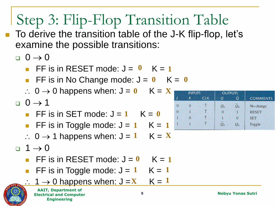
Step 3: Flip-Flop Transition Table To derive the transition table of the J-K flip-flop, let’s
examine the possible transitions:
0 0
FF is in RESET mode: J = K =
FF is in No Change mode: J = K =
0 0 happens when: J = K =
0 1
FF is in SET mode: J = K =
FF is in Toggle mode: J = K =
0 1 happens when: J = K =
1 0
FF is in RESET mode: J = K =
FF is in Toggle mode: J = K =
1 0 happens when: J = K =
0 1
0 0
0 X
0 1
1 1
1 X
0 1
1 1
1 X

10 AAIT, Department of
Electrical and Computer Engineering
Nebyu Yonas Sutri
Step 3: Flip-Flop Transition Table
1 1
FF is in SET mode: J = 1, K = 0
FF is in No change mode: J = 0, K = 0
1 1 happens when: J = X, K = 0
The J-K transition (or excitation) table is:
OUTPUT TRANSITIONS FLIP-FLOP INPUTS
Q Q+ J K
0
0
1
1
0
1
0
1
0 X
1 X
X 1
X 0

11 AAIT, Department of
Electrical and Computer Engineering
Nebyu Yonas Sutri
Step 4: Circuit Excitation Table
Derived from the next-state table and flip-flop
transition table:
E.g. 3-bit Gray code counter
PRESENT STATE NEXT STATE Excitation Inputs
Q2 Q1 Q0 Q2 Q1 Q0 J2 K2 J1 K1 J0 K0
0
0
0
0
1
1
1
1
0
0
1
1
1
1
0
0
0
1
1
0
0
1
1
0
0
0
0
1
1
1
1
0
0
1
1
1
1
0
0
0
1
1
0
0
1
1
0
0
0
0
0
1
X
X
X
X
X
X
X
X
0
0
0
1
0
1
X
X
X
X
0
0
X
X
0
0
0
1
X
X
1
X
X
0
1
X
X
0
X
0
1
X
X
0
1
X
OUTPUT TRANSITIONS FLIP-FLOP INPUTS
Q Q+ J K
0
0
1
1
0
1
0
1
0 X
1 X
X 1
X 0

12 AAIT, Department of
Electrical and Computer Engineering
Nebyu Yonas Sutri
Step 4: Circuit Excitation Table
Derived from the next-state table and flip-flop
transition table:
E.g. 3-bit Gray code counter
PRESENT STATE NEXT STATE Excitation Inputs
Q2 Q1 Q0 Q2 Q1 Q0 J2 K2 J1 K1 J0 K0
0
0
0
0
1
1
1
1
0
0
1
1
1
1
0
0
0
1
1
0
0
1
1
0
0
0
0
1
1
1
1
0
0
1
1
1
1
0
0
0
1
1
0
0
1
1
0
0
0
0
0
1
X
X
X
X
X
X
X
X
0
0
0
1
0
1
X
X
X
X
0
0
X
X
0
0
0
1
X
X
1
X
X
0
1
X
X
0
X
0
1
X
X
0
1
X
OUTPUT TRANSITIONS FLIP-FLOP INPUTS
Q Q+ J K
0
0
1
1
0
1
0
1
0 X
1 X
X 1
X 0

13 AAIT, Department of
Electrical and Computer Engineering
Nebyu Yonas Sutri
Step 4: Circuit Excitation Table
Derived from the next-state table and flip-flop
transition table:
E.g. 3-bit Gray code counter
PRESENT STATE NEXT STATE Excitation Inputs
Q2 Q1 Q0 Q2 Q1 Q0 J2 K2 J1 K1 J0 K0
0
0
0
0
1
1
1
1
0
0
1
1
1
1
0
0
0
1
1
0
0
1
1
0
0
0
0
1
1
1
1
0
0
1
1
1
1
0
0
0
1
1
0
0
1
1
0
0
0
0
0
1
X
X
X
X
X
X
X
X
0
0
0
1
0
1
X
X
X
X
0
0
X
X
0
0
0
1
X
X
1
X
X
0
1
X
X
0
X
0
1
X
X
0
1
X
OUTPUT TRANSITIONS FLIP-FLOP INPUTS
Q Q+ J K
0
0
1
1
0
1
0
1
0 X
1 X
X 1
X 0

14 AAIT, Department of
Electrical and Computer Engineering
Nebyu Yonas Sutri
Step 4: Circuit Excitation Table
Derived from the next-state table and flip-flop
transition table:
E.g. 3-bit Gray code counter
PRESENT STATE NEXT STATE Excitation Inputs
Q2 Q1 Q0 Q2 Q1 Q0 J2 K2 J1 K1 J0 K0
0
0
0
0
1
1
1
1
0
0
1
1
1
1
0
0
0
1
1
0
0
1
1
0
0
0
0
1
1
1
1
0
0
1
1
1
1
0
0
0
1
1
0
0
1
1
0
0
0
0
0
1
X
X
X
X
X
X
X
X
0
0
0
1
0
1
X
X
X
X
0
0
X
X
0
0
0
1
X
X
1
X
X
0
1
X
X
0
X
0
1
X
X
0
1
X

15 AAIT, Department of
Electrical and Computer Engineering
Nebyu Yonas Sutri
Step 5: Karnaugh Maps

16 AAIT, Department of
Electrical and Computer Engineering
Nebyu Yonas Sutri
Step 5: Karnaugh Maps
PRESENT STATE NEXT STATE
Q2 Q1 Q0 Q2 Q1 Q0 J2 K2 J1 K1 J0 K0
0
0
0
0
1 1
1
1
0
0
1
1
1 1
0
0
0
1
1
0
0 1
1
0
0
0
0
1
1 1
1
0
0
1
1
1
1 0
0
0
1
1
0
0
1 1
0
0
0
0
0
1
X X
X
X
X
X
X
X
0 0
0
1
0
1
X
X
X X
0
0
X
X
0
0
0 1
X
X
1
X
X
0
1 X
X
0
X
0
1
X
X 0
1
X

17 AAIT, Department of
Electrical and Computer Engineering
Nebyu Yonas Sutri
Step 5: Karnaugh Maps

18 AAIT, Department of
Electrical and Computer Engineering
Nebyu Yonas Sutri
Step 6: Logic Expression for Flip-Flop
Inputs Derive the logic expression for the flip-flop
inputs from K-map simplification.
E.g. 3-bit Gray code counter
012
012
021
021
1212120
1212120
QQK
QQJ
QQK
QQJ
QQQQQQK
QQQQQQJ
19 AAIT, Department of
Electrical and Computer Engineering
Nebyu Yonas Sutri
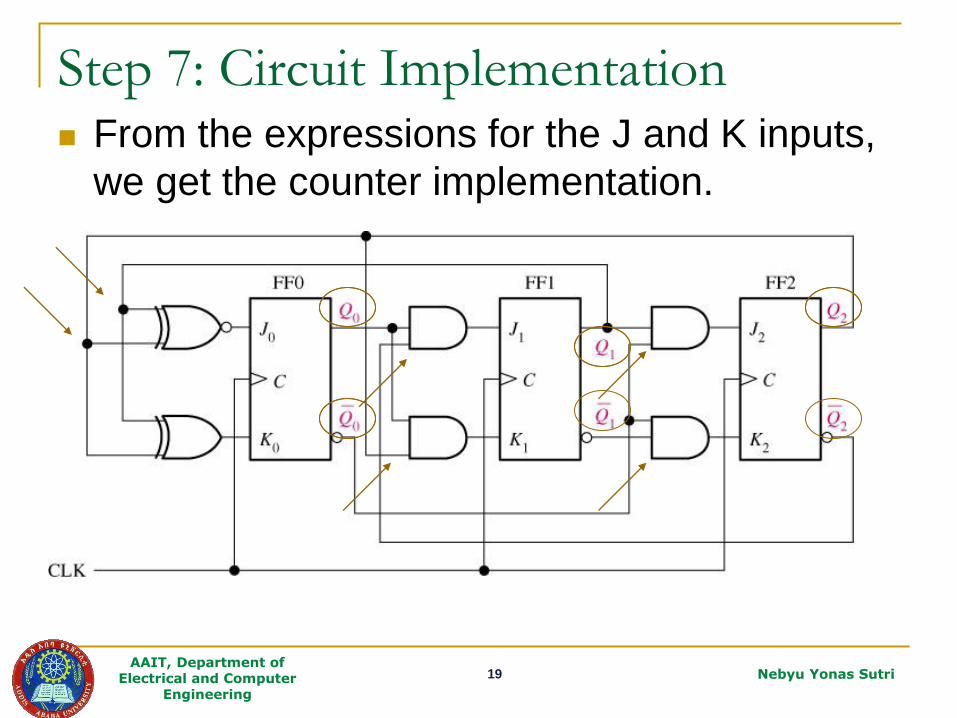
Step 7: Circuit Implementation From the expressions for the J and K inputs,
we get the counter implementation.

20 AAIT, Department of
Electrical and Computer Engineering
Nebyu Yonas Sutri
Exercise
Design a 3-bit Gray code counter using D-flip flops
PRESENT STATE NEXT STATE Excitation Inputs
Q2 Q1 Q0 Q2 Q1 Q0 D2 D1 D0
0
0
0
0
1
1
1
1
0
0
1
1
1
1
0
0
0
1
1
0
0
1
1
0
0
0
0
1
1
1
1
0
0
1
1
1
1
0
0
0
1
1
0
0
1
1
0
0
0
0
0
1
1
1
1
0
0
1
1
1
1
0
0
0
1
1
0
0
1
1
0
0

21 AAIT, Department of
Electrical and Computer Engineering
Nebyu Yonas Sutri
K-Map Simplification
0 1
00 0 0
01 1 0
11 1 1
10 0 1
Q2Q1
Q0 0 1
00 0 1
01 1 1
11 1 0
10 0 0
Q2Q1
Q0 0 1
00 1 1
01 0 0
11 1 1
10 0 0
Q2Q1
Q0
02012 QQQQD 02011 QQQQD 12122 QQQQD

22 AAIT, Department of
Electrical and Computer Engineering
Nebyu Yonas Sutri
Design the three bit gray counter using D
Flip-Flops individually.
Design an even bit counter in the following
counting sequence (0,2,4,6,8,0)
Design an odd bit counter in the following
counting sequence (1,3,5,7,9,1)
What to Do this Week?


