
Dye Sensitized Solar Cells (DSSCs)
and solar energy conversion

The Solar Spectrum
2

Anatomy of the leaf
3

4
A spectrum of incident solar radiation at the Earth’s
surface featuring superimposed absorption spectra of
chlorophyll a (—), chlorophyll b (—), bacteriochlorophyll
a (—) and bacteriochlorophyll b (—).
[recorded in methanol/ethanol solution].
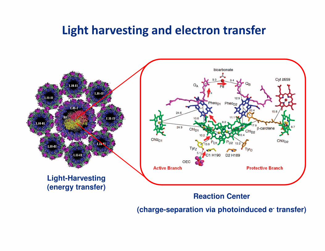
Light-Harvesting(energy transfer)
Reaction Center
(charge-separation via photoinduced e- transfer)
Light harvesting and electron transfer

Solar cell efficiencies (2013)
6
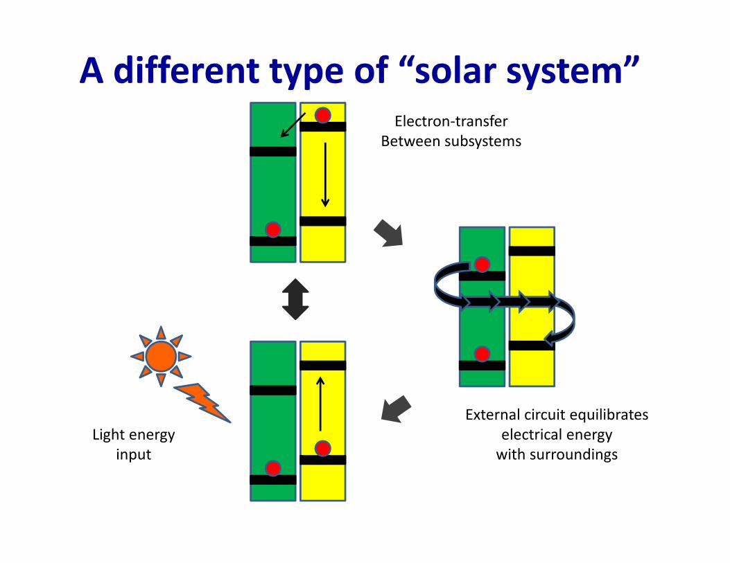
A different type of “solar system”
Light energy
input
Electron-transfer
Between subsystems
External circuit equilibrates
electrical energy
with surroundings

Current state-of-the-art
organic photovoltaics
8
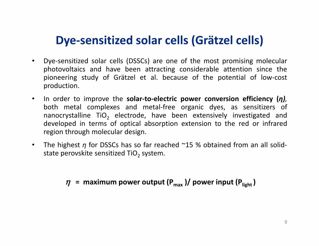
Dye-sensitized solar cells (Grätzel cells)
• Dye-sensitized solar cells (DSSCs) are one of the most promising molecularphotovoltaics and have been attracting considerable attention since thepioneering study of Grätzel et al. because of the potential of low-costproduction.
• In order to improve the solar-to-electric power conversion efficiency (η),both metal complexes and metal-free organic dyes, as sensitizers ofnanocrystalline TiO2 electrode, have been extensively investigated anddeveloped in terms of optical absorption extension to the red or infraredregion through molecular design.
• The highest η for DSSCs has so far reached ~15 % obtained from an all solid-state perovskite sensitized TiO2 system.
ηηηη = maximum power output (Pmax )/ power input (Plight )
9

• A DSSC is comprised of a photoanode and cathode electrode, with an interstitial
redox mediator containing electrolyte, connected via an external circuit.
• The photoanode consists of an optically transparent electrode (OTE) surface
[typically fluorine-doped tin oxide (FTO) glass], with a mesoporous layer (ca. 10
mm thickness) of anatase TiO2 nanoparticles (ca. 10-20 nm diameter) boasting a
remarkable surface area (> 1000 cm-2).
• The dye sensitizer is adsorbed on the high surface area TiO2 by covalent
attachment allowing a large absorption cross section (light harvesting).
• This adsorption process utilizes appropriate functional groups on the dye molecule
for dye immobilization, carboxylic and phosphonic acid tethers being the most
commonly used.
• The anode (counter electrode) typically consists of platinized FTO glass.
Just like chlorophyll in natural photosynthesis the dye typically plays the role of
light harvester and electron transfer agent.
10

“Anatomy”
of a
DSSC
11

Light harvesting in DSSCs
12

State of the art in DSSCs
Snaith et al. Science 2012, 338, 643-647.
Graetzel et al. Nature 2013 499, 316-319.
CH3NH3PbI3 perovskite sensitized TiO2

Champion molecular based DSSC dyes
S SN
O
O
Se SO
OHN
OO
n-C6H12 n-C6H12
JSC = 17.94 mA.cm-2
VOC = 770 mV
FF = 0.730
= 10.3 %
C219 dye
N
N
N
NSCN
SCNRu
CO2H
CO2NaC106 dye
JSC = 19.78 mA.cm-2
VOC = 758 mV
FF = 0.779
= 12.10 %
S
S
ISC = short circuit current (mA)
A = area (cm-2)
JSC = JSC /A = short circuit current density (mA.cm-2)
VOC = open circuit voltage (mV)
FF = f ill factor
I0 = incident light f lux (mW.cm-2)
= power conversion eff iciency
Sn-C6H12
Sn-C6H12
JSC = 17.30 mA.cm-2
VOC = 965 mV
FF = 0.71
= 11.9 %
YD2-o-C8 dye
N
NN
N
N
C6H13
C6H13
O O
O O
CO2H
C8H17 C8H17
C8H17C8H17
Zn
Yu Q. e. atl ACS Nano. 2010, 4, 6032.
Zeng et. al Chemistry of Materials 2010, 22, 1915.
Yella et al. Science 2011, 334 (6056), 629-634.

Operation of Dye Sensitized Solar Cells
Graetzel M. Nature 2001, 414, 338.
• Charge separation and charge recombination are competitive!
E(V)vsNHE
(iv)
(vii)

Semiconductor band energies
16
• Band positions of several
semiconductors in contact with
aqueous electrolyte at pH 1.
• The lower edge of the
conduction band (red color)
and upper edge of the valence
band (green color) are
presented along with the band
gap in electron volts.
• The energy scale is indicated in
electron volts using either the
normal hydrogen electrode
(NHE) or the vacuum level as a
reference.
• On the right side the standard
potentials of several redox
couples are presented against
the standard hydrogen
electrode potential.
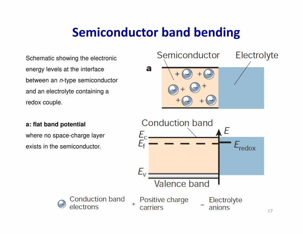
Semiconductor band bending
17
Schematic showing the electronic
energy levels at the interface
between an n-type semiconductor
and an electrolyte containing a
redox couple.
a: flat band potential
where no space-charge layer
exists in the semiconductor.

Semiconductor band bending
18
Schematic showing the electronic
energy levels at the interface
between an n-type semiconductor
and an electrolyte containing a
redox couple.
b: accumulation layer
where excess electrons have been
injected into the solid producing a
downward bending of the
conduction and valence band
towards the interface.

Semiconductor band bending
19
Schematic showing the electronic
energy levels at the interface
between an n-type semiconductor
and an electrolyte containing a
redox couple.
C: depletion layer
where electrons have moved from
the semiconductor to the
electrolyte, producing an upward
bending of the bands

Semiconductor band bending
20
Schematic showing the electronic
energy levels at the interface
between an n-type semiconductor
and an electrolyte containing a
redox couple.
d: inversion layer
where the electrons have been
depleted below their intrinsic
level, enhancing the upward band
bending and rendering the
semiconductor p-type at the
surface.

Scan rate 10mV/s. In each case: Fourth consecutive cycle depicted. Thickness: x and x , 4.5μm ; x, 4.4 μm
-50x10-6
-40
-30
-20
-10
0
10
20
30
CU
RR
EN
T D
EN
SIT
Y / A
cm
-2 µ
m-1
-0.7 -0.6 -0.5 -0.4 -0.3 -0.2
ELECTRODE POTENTIAL vs. Ag/AgCl, 3M KCl
5.5 m LiTFSI in water ACID pH=2.6 ACID pH=3.6 NEUTRAL
Compare bare titanium dioxide currents
for 5.5m LiTFSI/water solutions of different pH.
Voltammogram shifts to positive directionwith increased acidity
Conduction band edge shift ,in conformity with theory
Blank TiO2 variable pH study

Fermi Level
http://www.acsu.buffalo.edu/~wie/applet/fermi/functionAndStates/functionAndStates.html

• Transparent (80%) in the visible
• Ideal electronic band energetics (wide bandgap semiconductor)
• High internal surface area (x700) / porosity (40-60%)
• Chemical and electrochemical stability
• “Right” surface chemistry for modification with dye sensitizers
• Mechanically rugged
• Good optoelectronic properties
• Commercially available
• “Proven” nanomaterial
The cathode material requires several combined properties and…
…undoped nanocrystalline (10 - 20nm) anatase TiO2 provides these properties.
Why TiO2 ?

• Screen-printed film
• 2-12 micron thick
• Uniform coating
• 80+% Transmission in the visible range
• Surface area ca. 85 m2/g
• Good adhesion to substrate
TiO2 films can be printed to achieve reliable device properties.

Preparation of TiO2 nanoparticle films
• TiO2 anatase
- nanoparticles size ~ 20 nm
- thin film thickness ~10 mm
8 hr.
Ti(i-PrO)4
dil. HNO3
TiO2 colloid
TiO2 Sol-gel
hydrolysis
peptidization
Autoclave 12 hrs. @ 400 0C
Film Deposition
Sintering 30 min. 450 0C
PEG addition
TiO2 mesoporous film
TiO2 anatase Raman
Rochford J.; Chu D.; Hagfeldt A.; Galoppini E. J. Am. Chem. Soc. , 2007, 129, 4655.25
blank & sensitized
TiO2 films with ZnTCPP

TiO2 & anchoring groups
26
Scanning electron micrograph of a
sintered mesoscopic TiO2 (anatase) film
supported on an FTO glass. The average
particle size is 20 nm.
Possible binding modes for a carboxylic acid anchoring group at TiO2 (M = Ti)

The mesoporous nanocrystalline effect
27
The incident-photon-to-current conversion
efficiency (IPCE) is plotted as a function of the
excitation wavelength.
a) Single-crystal anatase TiO2.
b) Nanocrystalline TiO2 anatase film.
FTO

Incident photon-to-current conversion efficiency
28
The (IPCE), sometimes referred to also as “external
quantum efficiency” (EQE), corresponds to the
number of electrons measured as photocurrent in
the external circuit divided by the monochromatic
photon flux that strikes the cell.
IPCEλλλλ = [(hc /e) JSC ]/[I0 λλλλ]
IPCEλλλλ = LHEλλλλ . φφφφinj . ηηηηcoll
LHEλ = light harvesting efficiency
φinj = quantum yield for charge injection
ηcoll = charge collection efficiency at FTO electrode
IPCE = monochromatic efficiency

Scattering Layer and TiCl4 Pre/Post-treatment
29
Deposition of a second inert layer of TiO2 is now standard practice to increase the
light harvesting efficiency.
Treatment with TiCl4 introduces a fresh layer of TiO2 across the FTO back
electrode and also increase conductivity throughout the mesoporous film
enhancing charge-collection kinetics – ultimately decreasing charge
recombination from FTO or TiO2 to the oxidized dye or mediator.

30
DSSC efficiency
ηηηη = Pmax / Plight
= (VOC . ISC . ff ) / (I0 . A) x 100
= (VOC . JSC . ff ) / I0 x 100
By increasing the resistive load on an
irradiated cell continuously from zero
(short circuit) to a very high value (open
circuit) one can determine the
maximum-power point, the point that
maximizes V×I; i.e. the load for which the
cell can deliver maximum electrical
power at that level of irradiation.
(The output power is zero in both the
short circuit and open circuit extremes)
VOC = open circuit voltage
ISC = short circuit current
A = area
JSC = short circuit current density = ISC / A
ff = fill factor = A1 / A2
I0 = incident light flux (e.g. AM 1.5)
A1
A2
Pmax
• Following absorption of incident light, the dye molecule undergoes rapid
transition (< fs) to an excited state electronic configuration.
• This metastable excited state (ττττ N719 = 12 ns) affords rapid charge injection (fs – ps)
from the singly occupied, lowest unoccupied molecular orbital (LUMO) into the
conduction band (CB) of the TiO2 semiconductor (ECB = -0.50 V vs. NHE) thus
creating a charge separated state, i.e. TiO2•−/dye•+ (charge injection).
• The ensuing fate of this exciton (electron/electron-hole pair) determines the
quantum yield for photocurrent generation and thus η for the DSC device.
• The excited state electron can diffuse to the back electrode FTO/TiO2 contact (ns –
ms) from where it is transported via an external circuit to the counter electrode. In
this scenario the ground state dye is regenerated by a redox mediator in the
electrolyte (typically I−/I3−, E0 = 0.35 V vs. NHE) and the circuit completed by
regeneration of the redox mediator at the counter electrode.
31
Kinetic competition in DSCs

(processes in kinetic competition have similar colors)
32

Nanorod & nanotube electrodes
base diameters ~ 40 nm
SEM images of ZnO nanotips films
Galoppini E.; Rochford J. et. al J. Phys. Chem. B, 2006, 110, 16159.
de Taccomi N. R. et. al J. Phys. Chem. C, 2009, 113, 2996.
Prof. K. Rajeshwar and Dr. N. de TaccomiThe University of Texas at Arlington
Prof. A. Hagfeldt & Dr. G. Boschloo, KTH StockholmProf. Y. Lu, Rutgers Piscataway.

Molecular engineering for DSSCs
• In general, the molecular structure of an organic dye for DSCs has been designed
and synthesized based on several basic concepts:
� energy matching of the highest occupied molecular orbital (HOMO) and the
lowest unoccupied molecular orbital (LUMO) of the dye with the energy levels
of I−/I3− redox potential and ECB of the TiO2 electrode, respectively.
� a donor-π-conjugation-linkage-acceptor (D-ππππ-A) structure required for a wide
range absorption extending to the near-infrared or infrared region.
� one or two anchoring groups such as carboxylic acid or phosphonic acid
groups are required for a strong adsorption onto the surface of TiO2.
� Steric/orientational design strategy for hindering charge recombination
processes.
34

• According to the reports of organic dyes used in DSSCs so far, the combination of a
triaryl amine (donor) with a cyanoacrylic acid (acceptor and anchor), brings about
good matching of the above-mentioned energy levels.
• Oligothiophenes have been successfully employed as the conjugation unit of the
dye molecule between the donor and acceptor groups, resulting in maximum
absorption bands shifting to the longer wavelength.
35
η = 10.3 %

Effect of Anchor Length on Charge Injection into TiO2
Prof. P. Piotrowiak at Rutgers University

Effect of Anchor Length on Open Circuit Voltage at TiO2
•The diode equation predicts a 59 mV increase in Voc for each order of magnitude decrease in the charge recombination rate constant for injected electrons with acceptors, ki[A]i, at room temperature provided that the electron injection flux into the semiconductor, Iinj, is constant.
•In efficient dye-sensitized solar cells with 1 sun irradiance (100 mW/cm2), the predominant acceptors are thought to be iodide oxidation products, I2 and/or I3
-
• Charge recombination rates decreased by a factor of 20 for 2 and 280 for 3 relative to 1 when studied in regenerative dye sensitized solar cells.
d = 7 Ǻ d = 18 Ǻ d = 24 Ǻ
Meyer G. J.; Galoppini E. et. al. J. Phys. Chem. B 2006, 110, 11044.


Fluorescence Emission Studies on Insulating ZrO2
550 600 650 700 750 800
ZrO2/Glass
p-ZnTCPP-[S]
m-ZnTCPP-[S]
m-ZnTCP2P-[S]
m-ZnTC(PEP)P-[S]
No
rmal
ised
Em
issi
on I
nte
nsi
ty
Wavelength (nm)
• ZrO2 behaves as an insulator precluding
electron injection from the lowest excited-state
of all porphyrins studied here.
(Ebg ~ 5 eV for ZrO2 ; Ebg ~3 eV for TiO2 and ZnO)
• H-type aggregation causes broadening
and convergence of emission bands.
• Aggregation can give rise to exciton diffussion
which may lower the charge injection efficiency.
• Emission bands of all meta-substituted porphyrins
remain resolved in contrast to p-ZnTCPP.
N N
NNZn
CO2- +NHEt3
CO2- +NHEt3
Et3HN+ -O2C
Et3HN+ -O2C

Photoelectrochemical Properties
400 500 600 700 8000
10
20
30
40
50
60
on TiO2/FTO
p-ZnTCPP-[S]
m-ZnTCPP-[S]
m-ZnTCP2P-[S]
m-ZnTC(PEP)P-[S]
IPC
E (
%)
Wavelength (nm)
cinjLHEIPCE ηφ ××=
1001240
)(% ××
×=
φλλ scI
IPCE
Photoelectrochemical properties of tetra(triethylammonium)carboxyporphyrin salts
PorphyrinIsc
(mA∙cm-2)
Voc
(V)ff
IPCE (%)
430 nm 570 nma 600nmb
p-ZnTCPP-[S] 0.39 0.44 0.54 18.50 1.44 (0.08) 0.86 (0.05)
m-ZnTCPP-[S] 3.33 0.51 0.41 58.60 29.40 (0.50) 16.30 (0.28)
m-ZnTCP2P-[S] 3.72 0.50 0.42 56.90 34.50 (0.61) 21.10 (0.37)
m-ZnTC(PEP)P-[S] 1.36 0.43 0.45 25.30 9.00 (0.36) 4.81 (0.19)
In parentheses are the a Q(1,0) and b Q(0,0) vs. Soret peak intensity ratios

• As the most widely used couple, I−/I3− has a favorable penetration ability into the porous
semiconductor film, fast dye regeneration and relatively slow recombination with injected
photoelectrons.
• Moreover, I−/I3− is the only redox couple which has been proven to have long term stability.
However, several disadvantages limit its industrial application:
� the corrosion of copper/silver lines, which are used to collect the electrons in large scale
modules making the production of long-term stable modules much more difficult
� the I3− and other possible polyiodides formed in the electrolyte absorb a considerable part of
the visible light, downgrading the efficiencies of DSSCs.
� The complex redox chemistry in the electrolyte causes great energy loss.
� The redox potential of I−/I3− limits the photovoltage.
To avoid these disadvantages, new kinds of redox couples have beendesigned and applied in DSSCs.
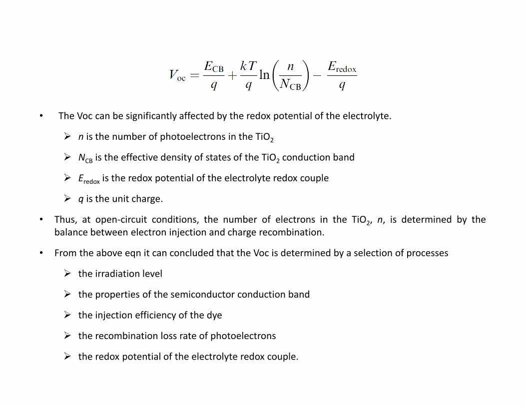
• The Voc can be significantly affected by the redox potential of the electrolyte.
� n is the number of photoelectrons in the TiO2
� NCB is the effective density of states of the TiO2 conduction band
� Eredox is the redox potential of the electrolyte redox couple
� q is the unit charge.
• Thus, at open-circuit conditions, the number of electrons in the TiO2, n, is determined by the
balance between electron injection and charge recombination.
• From the above eqn it can concluded that the Voc is determined by a selection of processes
� the irradiation level
� the properties of the semiconductor conduction band
� the injection efficiency of the dye
� the recombination loss rate of photoelectrons
� the redox potential of the electrolyte redox couple.

• Generally, n is considerably lower than NCB, and the maximum Voc is therefore determined by the
difference between the ECB of TiO2 and the Eredox of the electrolyte.
• Therefore, the redox potential of the redox system plays a key role in the Voc obtained in a DSSC.
• For the I−/I3− redox couple, the possibilities to increase the Voc are limited.
• Some modifications can be achieved by changing the concentrations and relative ratio of iodide and
iodine, but nevertheless the redox potential of the redox system is more or less fixed.

• Otherwise, in the conventional I−/I3− based
electrolyte, the redox mechanisms are
complicated. The regeneration is a multi
charge-transfer process whose exact
mechanism is still debated, but a two-step
process is generally accepted.
• In the first step of the dye-regeneration
process, the oxidized dye and iodide lead to
the formation of a diiodide radical (I2•−).
• The second step follows when the formed I2•−
disproportionates into I− and I3− . This leads
to a large loss in potential equal to the
difference between I− and I2•− redox
potentials (approximately 0.4 eV in
acetonitrile)

• CoII-complexes are commonly in the
high spin state, and CoIII-complexes
are in the low spin state.
• Therefore, CoII-complexes are more
reactive than CoIII-complexes.
• CoII in the electrolyte performs the
function of regenerating the
sensitizer in the photoanode
because of its higher reactivity.
• At the counter electrode, CoIII is
catalyzed to obtain an electron, and
converted to CoII.
• Co-based complex redox shuttles
have the advantage of a tunable
redox potential obtained through
modification of the ligands.
Co(III/II) mediators

• The efficiency obtained was initially
much lower than for DSSCs based on
the I−/I3− electrolyte.
• CoIII is more likely to experience
recombination with photoelectrons
from the TiO2 CB than I3−.
• Li+ as an electrolyte additive increases
the electron lifetime for a CoIII/II based
DSSCs due to a decrease in local conc.
of CoIII at the TiO2 surface.
• TBP (tert-butyl pyridine) facilitates
charge transfer from CoII to the dye
cation by reducing the reorganization
energy between CoII and CoIII.
• A thin Al2O3 blocking layer over the
mesoporous TiO2 surface has also
been used to minimize the charge
recombination
Co(III/II) mediators

• A major disadvantage of CoIII/II basedDSSCs is how the photovoltaic
performance is constrained by mass-
transport limitations of the mediator.
• Elliot et al. have found that the
effective diffusion coefficient of
Co(dtb-bpy)33+ is about one order of
magnitude slower than that of I3−.
• This may be attributed to the greater
size and slower bulk diffusion of
Co(dtb-bpy)33+, greater viscosity of
cobalt complex solutions, and a
possible electrostatic surface
interaction of Co(dtb-bpy)33+/2+
within the TiO2 film.
Co(III/II) mediators
• In 2009, Sun reported a new strategy of organic dye design by adding multiple alkoxyl
chains to the donor part of D–π–A dyes. The most efficient dye, D35, containing four
insulating butoxy chains efficiently prevent photoelectrons in TiO2 from recombining
with redox species in the electrolyte.
• In 2010, Hagfeldt and co-workers introduced the dye D35 to the Co-complex redox
system, an overall conversion efficiency of 6.7% with open-circuit potentials of more
than 0.9 V under 100 mW cm-2 AM1.5 G illumination using the combination of dye D35
and a Co(bpy)33+/2+ redox system.
• The key strategy was to reduce the recombination losses with blocking hydrophobic
groups on the sensitizing dyes, rather than, as in previous studies, on the Co
complexes.
• This approach allows the use of non-substituted Co complexes with higher diffusion
constants.
• The strategy thus successfully reduces both the recombination losses and, at least
partly, the mass-transport limitations.
Co(III/II) mediators
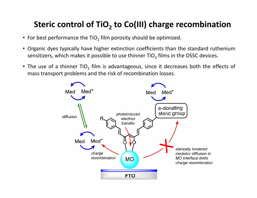
• For best performance the TiO2 film porosity should be optimized.
• Organic dyes typically have higher extinction coefficients than the standard ruthenium
sensitizers, which makes it possible to use thinner TiO2 films in the DSSC devices.
• The use of a thinner TiO2 film is advantageous, since it decreases both the effects of
mass transport problems and the risk of recombination losses.
Steric control of TiO2 to Co(III) charge recombination

50

Current transients measured at an illumination intensity of 1000 W m-2 for DSSCs sensitized with D35
Current transients measured at an illumination intensityof 1000 W m-2 for [Co(bpy)3]
2+/3+ based DSSCs sensitized with D35 using a different thickness of TiO2.
Current density versus applied potential curves under 1000 W m-2
AM1.5G for DSSCs sensitized with D35. The electrolytes were 0.5 M Co(bpy)3(PF6)2, 0.1 M Co(bpy)3(PF6)3, 0.5 M TBP, and 0.1 M LiClO4 in acetonitrile or 0.6 M 1-butyl-3-methylimidazoliumiodide, 0.03 M I2, 0.5 M TBP, and 0.1 M guanidiniumthiocyanate in acetonitrile, respectively.

Record efficiency for a molecular DSSC sensitizerE(V)vsNHE
FTO
FTO
Yella et al. Science 2011, 334 (6056), 629-634.

Device Fabrication by Graetzel Lab
Yella et al. Science 2011, 334 (6056), 629-634 (Taken from supp info).
• The photoanode used in this study consists of thin TiO2 electrodes comprising a 5
μm mesoporous TiO2 layer (particle size, 20 nm, pore size 32 nm) and a 5 μm
TiO2 scattering layer (particle size, 400 nm).
• Thickness and the porosity of the photoanode was found to be very crucial in the
cobalt based DSSCs. Porosity of the TiO2 paste was increased (from 23 nm pore
size to 32 nm pore size) and the thickness was reduced compared to I-/I3- based
devices to avoid the mass transport limitations in cobalt based devices.
• The working electrode was prepared by immersing the 10 μm (5 μm thick
transparent layer +5 μm thick scattering layer) TiO2 film into dye solution for 18 h.
• A thermally platinized FTO glass counter electrode and the working electrode were
then sealed with a 25 μm thick hot-melt film (Surlyn, by heating the system at
100°C. Devices were completed by filling the electrolyte by pre-drilled holes in the
counter electrodes and finally the holes were sealed with a Surlyn sheet and a thin
glass cover by heating. A black mask (6x6 mm2) was used in subsequent
photovoltaic studies.

Absorption spectra & CV of porphyrins YD2 and YD2-o-C8
Yella et al. Science 2011, 334 (6056), 629-634.

Optimization of electrolyte composition
Yella et al. Science 2011, 334 (6056), 629-634 (Taken from supp info).

Performance at various light intensities (VOC depdenence)
Yella et al. Science 2011, 334 (6056), 629-634 (Taken from supp info).

J-V and IPCE DSSC characterization
Yella et al. Science 2011, 334 (6056), 629-634.

APCE vs IPCE
Yella et al. Science 2011, 334 (6056), 629-634.
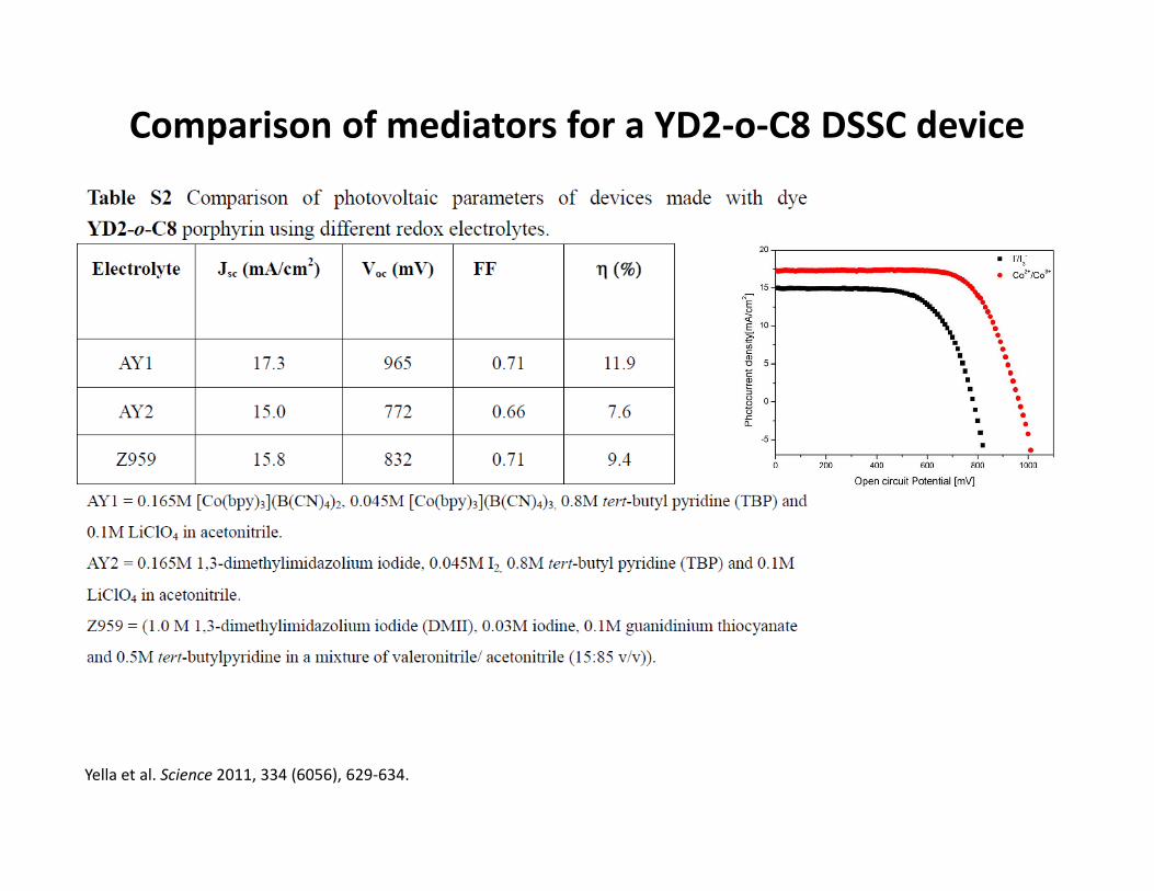
Comparison of mediators for a YD2-o-C8 DSSC device
Yella et al. Science 2011, 334 (6056), 629-634.

• Both Hagfeldt and Graetzel research groups have reported on the significant
efficiency enhancement of Z907 vs N719 when used with Co(III/II) mediators.
Ru sensitizers & Co(III/II) mediators
Liu et al. J. Phys. Chem. C 2011, 115, 18847-18855.
Feldt et al. J. Am. Chem. Soc. 2010, 132, 16714.

SnO2 – Ru– iodide – Pt based DSSCs ?
-1.0
-0.5
0.0
0.5
1.0
1.5
2.0
2.5
3.0
3.5
3.2
eV
TiO2
3.6
eV
SnO2ECB
ECB
EVB
EVB
EF
EF
I3 /IVOC VOC

TiO2 – Ru– iodide – Pt based DSSCs

TiO2 – Ru– iodide – Pt based DSSCs

SnO2 – Ru– iodide – Pt based DSSCs ?
-1.0
-0.5
0.0
0.5
1.0
1.5
2.0
2.5
3.0
3.5
3.2
eV
TiO2
3.6
eV
SnO2ECB
ECB
EVB
EVB
EF
EF
I3 /IVOC VOC

p-Type DSSCs (a reverse Graetzel cell)
E(V)vsNHE
charge
recombination
• Can we take a similar approach to p-type DSSCs ?

Voc = 350 mV in a NiO, I/I3 p-DSC system. A solar to electric conversion efficiency (Z) of 0.14% was achieved.

Tandem np-DSSCs
ECB
D0/D+
D*
hv
electron
transfer
e-
e-
e-
FTO TiO2 Dye (donor) Electrolyte Dye (acceptor) p-NiO FTO
EF
EVB
-1.5
-1.0
-0.5
0.0
0.5
1.0
1.5
D0/D+
D*
hv
electron
transfer
e-
e-
e-
e-
Red Ox
Mediator e-
Voc''
dif f usion
charge
recombination
EF
-1.5
-1.0
-0.5
0.0
0.5
1.0
1.5
e-
e-
Voc'
Voc = Voc' + Voc
''
e-

Current-density–voltage characteristics for dyes 1–3; green: 1; blue: 2; red: 3. in a p-type NiO device.c, Current–voltage characteristics of a tandem solar cell (black) as well as p-DSCs (red) and n-DSCs (green) under illumination (AM1.5, 1,000Wm 2, solid lines) and in the dark (dashed lines).Identical NiO and TiO2 films were used for the construction of the tandem, p- and n-DSC.


“By using suitable catalyzers, it should be
possible to transform the mixture of water
and carbon dioxide into oxygen and
methane, or to cause other endo-energetic
processes.”
International Conference of Applied Chemistry, New York,
September 11, 1912.
Solar Generation of Fuels
hν
H2O H2 + ½ O2
CO2 + 2H2O CH3OH + 1/2 O2
hν
Prof. Giacomo Ciamician (1857–1922)
“Godfather of photochemistry”
Prof. Ciamician surveys his collection of tubes and flasks
exposed to the sun on the balcony of his institute
At the University of Bologna from 1889 to
1922 G. Ciamician was inspired by the
ability of plants to make use of solar
energy, he was the first scientist to
investigate photochemical reactions in a
systematic way.
71

Heterogeneous Catalysts for
Water Oxidation, Proton reduction and CO2
reduction inspired by photosynthesis
photoanode
cathode
anode
cathode

Gray H., Nocera D., Nature 2008, 452.
H+ + e-→ H• E°= -2.20 V (1)
2H+ + 2e- → H2 E°= 0.00 V (2)
2OH• + 2H+ + 2e- → 2H2O E°= +2.72 V (3)
H2O2 + 2H+ + 2e- → 2H2O E °= +1.76 V (4)
O2 + 4H+ + 4e- → 2H2O E°= +1.23 V (5)
( E° @ pH 0 vs. NHE )
proton
reduction
+
water
oxidation
overall
water
splitting
Why study water oxidation ?

∆∆∆∆G≠ = overpotential
O2 + 2H2 ∆∆∆∆G0 = -nFEcell
E
Reaction coordinate
∆∆∆∆G≠ = overpotential
2H2O
2H2O → O2 + 4H+ + 4e- E0Ox = -1.23 V (1)
4H+ + 4e- → 2H2 E0Red = 0.00 V (2)
2H2O → 2H2 + O2 E cell = -1.23 V (3)
∆G0 = +237 kJ mol-1
Water Oxidation =

Photosynthesis
Light-Harvesting(energy transfer)
Reaction Center
(charge-separation via photoinduced e- transfer)
6CO2 + 6H2O + hv → C6H12O6 + 6O2

The oxygen evolving complex of PSII
H2O oxidation by oxygen evolving complex (OEC) via
proton-coupled e- transfer (dark reaction)
C. W. Hoganson and G. T. Babcock, Science 1997, 277 (5334), 1953-1956.

Water Oxidation and the Blue-Dimer
• Homogenous catalyst
• Electrochemically Oxidizes water in absence of
light
similar to Mn4CaO OEC in photosystem II
• Inefficient catalyst (only 25 turnovers)
• Mechanism has been extensively investigated by
Meyer, Hurst, Baik and others
• Proton-coupled oxidation of RuIII → RuIV → RuV
• Mechanism for O2 evolution still unknown
T.J. Meyer et al. JACS 1982, 104, 4030
RuIIIO
RuIII
OH2 OH2
(bpy)2 (bpy)2 RuIVO
RuIV
OH OH
(bpy)2 (bpy)2
RuVO
RuV
O O
(bpy)2 (bpy)2
RuIVO
RuIII
OH OH2
(bpy)2 (bpy)2
-H+, -e−−−− -H+, -e−−−−
-H+, -e−−−−
RuVO
RuIV
O OH
(bpy)2 (bpy)2
-H+, -e−−−−
?
2H2O
O2

WOC’s Inspired by Blue-Dimer
Llobet ’04
Thummel ‘06
Grätzel ‘87
• Loss of 4 e- and 4 H+ with
formation of O-O bond
• Low over-potential
• High turnover number
(stability)
• Steric requirements
•Tanaka dimer > 30,000 TN
“Forum on Making Oxygen” Inorg. Chem., 2008, 47, 1697-2232
Blue dimerT.J. Meyer ‘82
N NN
= terpyridine
Tanaka ‘03

N NN
= terpyridine
Q = 3,5-Cl2
Q = 3,6-tBu2
• Excellent electrocatalyst for water oxidation
• TN > 30,000 (1.7 V vs. Ag/AgCl @ pH 4)
• Unlike the Blue Dimer catalyst (RuIII/RuV) two Ru
atoms predominantly +2 during entire catalytic
cycle
• Active redox couples are SQ/Q
• Catalytic activity controlled by a delicate balance
of the charge distribution over the Q-Ru-OH
framework to make the O-O bond
• Steric hindrance is required to suppress the
deleterious Ru-O-Ru formation and allow the
desired Ru-O-O-Ru formation
• Substitution of bpy for the quinone ligands results
in negligible catalytic activity!!
The Tanaka Dimer
K. Tanaka et al., Inorg. Chem., 2001, 40, 329 & J. Am. Chem. Soc., 2003, 125, 6729.
Muckerman J. et al “Forum on making Oxygen”, Inorg. Chem. 2008, 47, 1787.

Tanaka monomer: Proton management !
Slope Description0 mV ET only 59 mV 1 e- 1H+ PCET30 mV 2 e- 1H+ PCET118 mV 1 e- 2H+ PCET
pKa aqua = 5.5 (calcd. 4.7)
pKa hydroxyl = 10.7 (calcd. 12.4)
(Square Wave Voltammetry)
pH0591.0)ln(*
| ⋅⋅−+=n
m
a
a
nF
RTEE
R
ORO
Tsai M.-K.; Rochford J.; Polyansky D. E.; Wada T.; Tanaka K.; Fujita E.; Muckerman J. Inorg. Chem., 2009, 48 (10), 4372.
• PCET occurs in PSII at OEC via adjacent Tyrosine residue (Tyz)
• PCET precludes build up of excess positive charge within the complex, i.e. at metal or ligand.
OH2
NN
NRu
O
O
II
2+

Mechanism of Tanaka Dimer for WOC (DFT)
Boyer J.; Rochford J.; Tsai M.-K.; Muckerman J.; Fujita E. Coord. Chem. Rev. 2010, 254, 309-330.
Tsai M.-K.; Rochford J.; Polyansky D. E.; Wada T.; Tanaka K.; Fujita E.; Muckerman J. Inorg. Chem., 2009, 48 (10), 4372.

Mononuclear water oxidation catalysts (WOC)
• Highly promising: less expensive, not as synthetically demanding
• Yet to be fully explored
J. J. Concepcion, J. W. Jurss, J. L. Templeton and T. J. Meyer. J. Amer. Chem. Soc. 2008, 130 (49), 16462-16463.

Natural
oxygen evolving complex
Artificial
oxygen evolving complex
S. Romain, L. Vigara and A. Llobet. Acc. Chem. Res. 2009, 42 (12), 1944-1953.

Requirements for CO2 reduction• One electron reduction of CO2 is unfavorable requiring an energy of -1.9 V.
• PCET and multi-electron transfer catalysts required to reduce large overpotentials
• Electricity as electron source (Electrochem)
• Photon as energy source (Photochem)
Comments Inorg. Chem. 1997, 19, 67
Coord. Chem. Rev. 1999, 185, 373
photoelectrochemistry
CO2 + 2H+ + 2e-
HCO2H
CO2 + e- CO2-
CO2 + 2H+ + 2e-
CO + H2O
CO2 + 4H+ + 4e- C + 2H2O
CO2 + 4H+ + 4e- H2CO + H2O
Reaction Eo (V)
-1.90
-0.61
-0.53
-0.20
-0.48
-0.38
-0.24
-1.55
-1.20
CO2 + 6H+ + 6e- CH3OH + H2O
CO2 + 8H++ 8e- CH4 + 2H2O
CO2-
+ e- CO22-
CO2 + 2e- CO22-
(i)
(ii)
(iii)
(iv)
(v)
(vi)
(vii)
(viii)
(ix)

Photocatalytic CO2 reduction by Re(I) carbonyls
• One of the most highly studied photocatalytic systems are the Re(I)
polypyridyl tricarbonyl systems first inspired by the Lehn catalyst.
ReCO
CO
CON
N
Cl
hv
TEOA
TEOA
CO
CO2
2 1 0 -1 -2
1 atm Ar
1 atm CO2
bkg Ar
bkg CO2
Potential (V) vs. NHE
Hawecker, J.; Lehn, J. M.; Ziessel, R., J. Chem. Soc. Chem. Comm. 1984, 328-330
• TN = 27
• TOF = 11 hr-1
• Φ = 0.14

Photocatalytic CO2 reduction by Re(I) carbonyls
• Ishitani has proposed a mechanism taking advantage of Re(bpy)(CO)3X complexes as both
photocatalyst and photosensitizer with one of the largest quantum yields reported to date at Φ = 0.59.
Takeda et al. J. Am. Chem. Soc. 2008, 2023.

Morris A.; Meyer G.; Fujita E. Acc. Chem. Res. 2009, 42, 1983-1994.


