1
Dual Drive-By-Wire Throttle Body Harness Installation
PN 558-411
Instruction Manual – 199R10593 1.0 Overview The Holley Dominator ECU has built in capability to control OEM type Drive-By-Wire (DBW) throttle pedals and throttle bodies for aftermarket installation. PN 558-411 is designed for use with dual throttle bodies. To ensure a safe and reliable installation, there are certain hardware requirements that must be followed: Only the following factory DBW throttle bodies have been pre-calibrated and approved for use with this harness:
GM P/N – 12570790 GM P/N – 12580760 GM P/N – 12605109 GM P/N – 12570800 GM P/N – 12580195
Only the following factory DBW throttle pedal assembly has been pre-calibrated and approved for use with this harness:
GM P/N – 10379038 2.0 Warnings! Use only the drive-by-wire wiring harness supplied by Holley. THIS HARNESS CAN NOT BE CUT, SHORTENED, LENGTHENED, TAILORED, OR MODIFIED UNDER ANY CIRCUMSTANCE! THE HARNESS CONTAINS PROTECTIVE SHIELDING / GROUNDED CABLING TO ENSURE PROPER OPERATION. DO NOT REMOVE OR MODIFY THE PROTECTIVE SHEATHING UNDER ANY CIRCUMSTANCES. HOLLEY ASSUMES NO LIABILITY FOR ANY INSTANCES ARISING DUE TO USE OF THROTTLE PEDALS, THROTTLE BODIES OR ASSOCIATED COMPONENTS NOT SPECIFICALLY APPROVED BY HOLLEY.
2
3.0 Installation Installation of both the drive-by-wire throttle bodies and pedal assembly should be performed by a professional, competent mechanic. It is important that the installation of both the throttle bodies and pedal assembly on an engine (not originally equipped with these components) be done in such a manner that assures proper operation of both components as intended by the OEM manufacturer.
The throttle bodies must be installed in such a manner that the throttle plate(s) are allowed to rotate freely. The pedal assembly must also be installed in such a manner that it is rigidly and securely mounted, yet does not put the pedal
in a bind, or put any mechanical stress on the electrical and electronic components. Proper positioning of the pedal is of the utmost importance.
The accelerator pedal must have adequate clearance throughout the range of its travel to prevent the possibility of the pedal coming in contact with any item that may cause it not to return to the “idle” position upon release. The accelerator pedal must also be mounted far enough away from the brake pedal as to allow for the vehicle’s brakes to be fully applied without the operator’s foot coming in contact with the D-B-W pedal.
The drive-by-wire pedal should be in a position such that it is lower than the brake pedal when the brake pedal is depressed. Installation of the wiring harness supplied by Holley must be done so that there is no chance the wiring may be cut or abraded.
Rubber grommets should be utilized wherever the harness passes thru a firewall / sheet metal panel. The DBW harness should never be routed in such a manner that it may come in contact with “noisy” electrical components or
wiring that may emit RFI and/or EMI noise. Typical “noisy” components and associated wiring in a vehicle would be spark plug wires, ignition coils, high energy ignition boxes, two-way radios (including CB’s), etc. Maintain a minimum of 5” of clearance to any of these types of components.
The harness is designed to be “plug-and-play” with the throttle bodies and pedal assembly indicated above. It should not be used for any other applications. 4.0 System Safeties Holley designed the drive-by-wire system to utilize a brake pedal switch input. This is wired to a +12v input from the brake pedal switch. If the brake pedal is depressed enough to activate the brake light switch, the following occurs:
The ECU will not allow a pedal position over 10%, no matter how far the pedal is pushed. This consequently limits the opening of the throttle bodies. Before a pedal value over 10% will be recognized, the following must occur in this order:
Brake pedal switch must be released Pedal position must go below 10%
Fuel flow is limited to 30 lb/hr as an additional safety.
IMPORTANT! INSTALLATION OF THIS SAFETY CIRCUIT IS REQUIRED WHEN USING THE DRIVE-BY-WIRE FEATURE!
DEFEATING OR NEGLECTING TO INSTALL THIS INPUT IS DONE SO AT THE USERS OWN RISK. THE USER ASSUMES ANY AND ALL LIABILITY FOR ANY DAMAGE, AS A RESULT OF A DRIVE-BY-WIRE MALFUNCTION.
Most drive-by-wire systems are designed so there are two position sensors on both the throttle body and the accelerator pedal assembly. This is done as a failsafe in the event that one of the position sensors should fail. Holley EFI systems require that both sets of sensors are functioning 100% properly. If any sensor moves from its calibrated position, the throttle body is immediately de-powered, forcing it to move to the factory “limp home” position. The “limp home” position is described in detail below. Whenever a fault is detected and the throttle body is de-powered, a fuel flow limit of 30 lb/hr is also introduced. 5.0 Throttle Body “Limp Home” Position Factory Drive-By-Wire Throttle Bodies have a “Limp Home” position. This is the position that the throttle body is at when no power is applied. It is typically enough air flow to allow a car to move at a speed of approximately 45 mph. This varies by manufacturer, but is the case with the GM throttle bodies this harness supports. However, when two throttle bodies are used, the speed may be noticeably higher. It should be strongly noted that this position allows MORE airflow than the engine uses for an idle position. If the throttle body goes into a “limp home” position due to a sensor failure or other reason, the engine will have more air and result in more power. This will require more brake pressure to be applied if a vehicle is in gear so that it does not move.
3
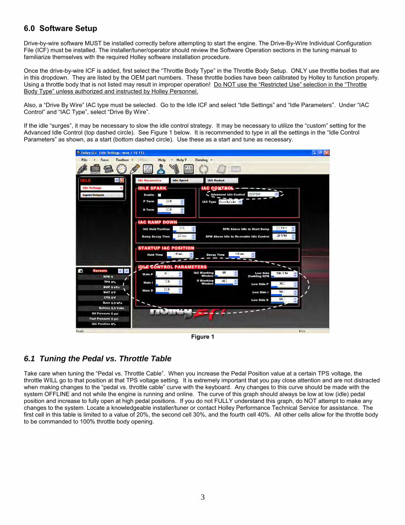
6.0 Software Setup Drive-by-wire software MUST be installed correctly before attempting to start the engine. The Drive-By-Wire Individual Configuration File (ICF) must be installed. The installer/tuner/operator should review the Software Operation sections in the tuning manual to familiarize themselves with the required Holley software installation procedure. Once the drive-by-wire ICF is added, first select the “Throttle Body Type” in the Throttle Body Setup. ONLY use throttle bodies that are in this dropdown. They are listed by the OEM part numbers. These throttle bodies have been calibrated by Holley to function properly. Using a throttle body that is not listed may result in improper operation! Do NOT use the “Restricted Use” selection in the “Throttle Body Type” unless authorized and instructed by Holley Personnel. Also, a “Drive By Wire” IAC type must be selected. Go to the Idle ICF and select “Idle Settings” and “Idle Parameters”. Under “IAC Control” and “IAC Type”, select “Drive By Wire”. If the idle “surges”, it may be necessary to slow the idle control strategy. It may be necessary to utilize the “custom” setting for the Advanced Idle Control (top dashed circle). See Figure 1 below. It is recommended to type in all the settings in the “Idle Control Parameters” as shown, as a start (bottom dashed circle). Use these as a start and tune as necessary.
Figure 1
6.1 Tuning the Pedal vs. Throttle Table Take care when tuning the “Pedal vs. Throttle Cable”. When you increase the Pedal Position value at a certain TPS voltage, the throttle WILL go to that position at that TPS voltage setting. It is extremely important that you pay close attention and are not distracted when making changes to the “pedal vs. throttle cable” curve with the keyboard. Any changes to this curve should be made with the system OFFLINE and not while the engine is running and online. The curve of this graph should always be low at low (idle) pedal position and increase to fully open at high pedal positions. If you do not FULLY understand this graph, do NOT attempt to make any changes to the system. Locate a knowledgeable installer/tuner or contact Holley Performance Technical Service for assistance. The first cell in this table is limited to a value of 20%, the second cell 30%, and the fourth cell 40%. All other cells allow for the throttle body to be commanded to 100% throttle body opening.
4
7.0 Checks To Perform After Installation and Before Starting Before starting an engine with Holley EFI equipped with drive-by-wire make sure the Global Folder is set up properly based on the “Software Setup” above. The drive-by-wire is initialized when the ignition is turned on. So if you send a Global Folder with a drive-by-wire ICF added to it for the first time, you must CYCLE THE IGNITION POWER FROM ON TO OFF AND THEN BACK ON to properly initialize the changes. BEFORE attempting to start the engine, perform the following checks:
1) PERFORM A TPS AUTOSET. Make sure the “Calibration Successful” message appears when you are done. This will calibrate the throttle pedal as well as cycle the throttle body(s) to calibrate them as well. You MUST perform this procedure before starting the engine. If you do not understand how to do this, go back and read the basic installation manuals!
2) With the ignition in the “on/run” position (DO NOT START ENGINE - ignition power on - engine off) slowly depress the accelerator pedal and have an assistant watch the throttle body plate. The throttle plate should move from closed to fully open as the pedal is depressed. Make sure the throttle plate returns to the “idle” position when the accelerator pedal is no longer depressed.
NOTE: If a TPS Autoset is not performed, no fuel will be injected. The car will NOT start. IF THE THROTTLE PLATE DOES NOT FUNCTION IN THE MANNER INDICATED ABOVE, FIND OUT WHY BEFORE YOU START THE ENGINE. Contact Holley Technical Support (270-781-9741), if necessary.
8.0 Drive-By-Wire DO’S and DON’TS DO
- Use only the Holley Supplied harness. - Have the pedal, throttle body, and harness installed by a competent professional.
DON’T
- Do not use wire other than the Holley supplied harness. - Do not cut, shorten, lengthen, or otherwise modify the drive-by-wire harness for any reason! - Do not run drive-by-wire harness past high voltage or “noisy” sources - Do not use this system if the pedal is not securely mounted as described in the instructions above. It must be SOLIDLY
mounted with adequate room for safe and proper operation. - Do not use this system if the throttle body is not properly mounted or have any potential of interference/binding of the throttle
plates. - Do not start the engine unless everything is operating properly.
9.0 Wiring If you are using DBW on an engine dyno, and are connecting the DBW pedal to the existing dyno throttle, make sure that the linkage is set up such that you get full, or almost full travel of the DBW pedal. If the travel is not enough, it will not allow for the TPS Autoset to occur properly. NOTE: Please refer to the following drawing for proper wiring installation.
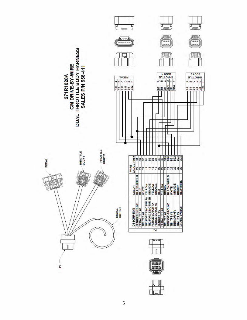
5

6
Holley Technical Support 1801 Russellville Road
Bowling Green, KY 42101 270-781-9741
www.holley.com
© 2012 Holley Performance Products, Inc. All rights reserved. 199R10593 Date: 1-17-12


