
Drums, Vessels, & Storage Tanks
Design Considerations

The Equipment List
� Vessels, including Reactors
� Towers
� Storage Tanks
�See User Added Equipment
Equip # Type Tray Dia Tray Spacing Ideal TraysReal Trays Op. Pressure Max Op. Pressure
mm m ft mm number number m ft KPA bar (guage)
TOWERS
Tower Dia Length or Height
VESSELS
Equip # Name Type Op. PressureMax Op. PressureOrientationMat'ls of Construction CAPCOSTBase
m ft m ft KPA bar (guage) horiz/vert vessel demister Equip# Cost
Diameter Length or Height

Vessels - General
�Wall Thickness
�determined by required pressure
� Process Engineer Determines Design Pressure
�See Web Notes
Normal Op. Pressure (Pro II)
Maximum Op. Pressure (Controls, S/U , S/D ...)
Design Pressure (Relief Valve Set Pressures,
Minimum Required Metal Thickness) Process Engineer
Maximum Allowable Working Pressure
(MAWP)- Actual Metal Thickness Used Fab Shop

Design Pressure
� Excessive design pressure causes equipment to be more expensive than is required
t = metal thickness, P = Design Pressure
Cc = Corrosion Allowance, Ej = Joint Efficiency 5
for cylindrical shells
tP ri⋅
S EJ⋅ P−Cc+

Vessels - General
General - Design Temperatures
� Allowable Stress Values are dependant on Temperature
� Temperature at Design Pressure must be stated
�Materials become brittle below certain temperatures - minimum design metal
temperature

Reflux Drums

Reflux Drum Sizing
� Assume a length to diameter Ratio of 3
� Therefore:
� Solve for diameter
vol πdia
2
2
⋅ 3 dia⋅( )⋅
diavol
π
4
3⋅
1
3
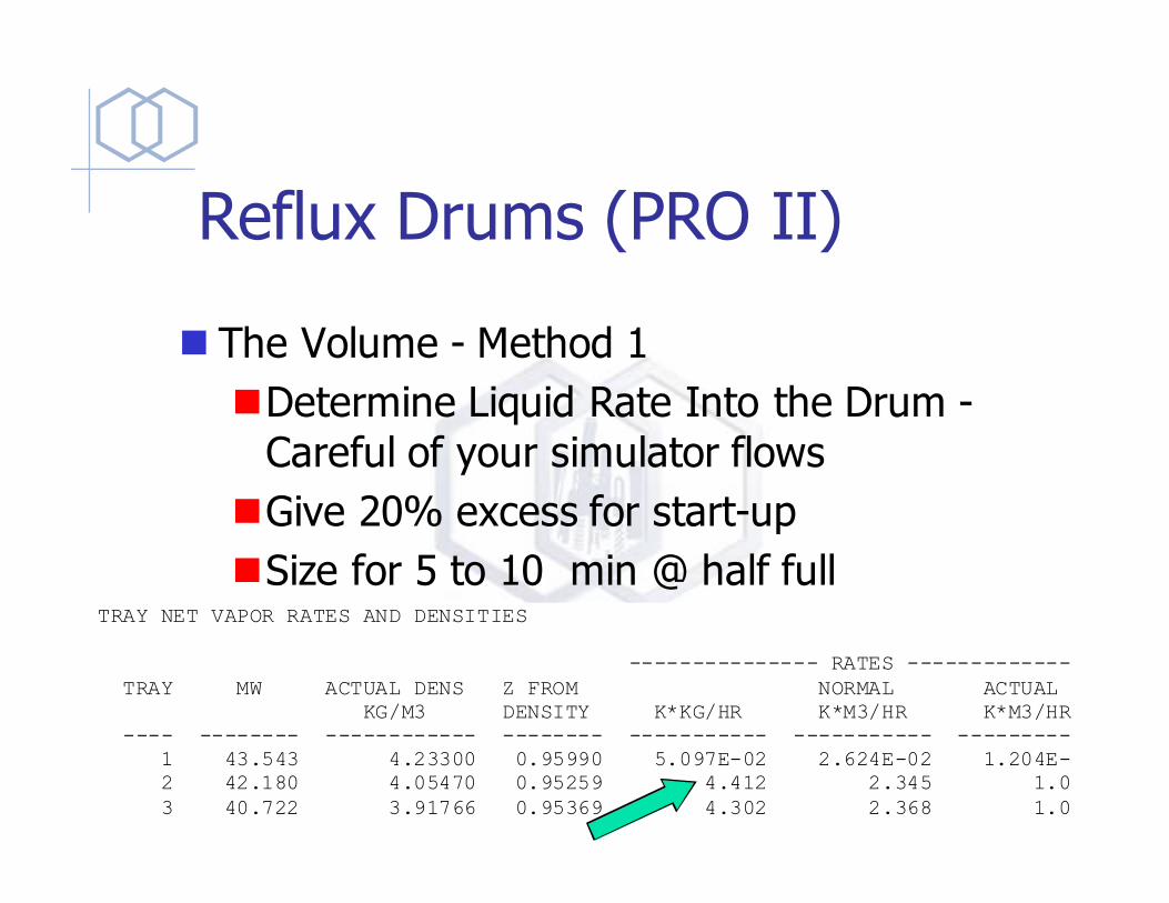
Reflux Drums (PRO II)
� The Volume - Method 1
�Determine Liquid Rate Into the Drum -
Careful of your simulator flows
�Give 20% excess for start-up
�Size for 5 to 10 min @ half full TRAY NET VAPOR RATES AND DENSITIES
--------------- RATES ---------------
TRAY MW ACTUAL DENS Z FROM NORMAL ACTUAL
KG/M3 DENSITY K*KG/HR K*M3/HR K*M3/HR
---- -------- ------------ -------- ----------- ----------- -----------
1 43.543 4.23300 0.95990 5.097E-02 2.624E-02 1.204E-02
2 42.180 4.05470 0.95259 4.412 2.345 1.088
3 40.722 3.91766 0.95369 4.302 2.368 1.098

General - Tanks/Vessels
� Method 2 - Hold Up Time (at half full)
� 2 to 32 minutes depending on quality of control for each outgoing stream
� 5 to 10 minutes is sufficient with modern control systems to handle minor upsets
� 30 minutes provides a 99% probability that an operator can determine cause of failure
� Engineering Judgement !
11

Vessels - Safety
� Vessel that can be isolated require Relief Valves

Vessels - Relief Valves

Vessels (Reactor)
� Sized on processing requirements
�Agitated vessels usually have L/D ~ 1
�Non agitated L/D ~ 3
�Superficial velocities
important?
�Fluidization of contents?
�Internal coils, external
jackets

Vessels (Reactor)
� Plug Flow Reactor Issues
�Residence Time / Volume - Pro II
�Pressure Drop - packed beds - ergun eqt.
(Perry’s)
�Back Mixing - Testing, CFD - L/D > 5

General - Tanks/Vessels
� Horizontal vs. Vertical
� Vertical preferred when:
�small liquid load
�limited plot space
�ease of level control is desired
12
�Horizontal preferred when:
�large liquid loads are involved, consequently hold-up will set the size �three phases are present

General - Tanks/Vessels
Mesh
Entrainment
Separator
36” + 1/2
feed nozzle
OD (48”
min)
12” + 1/2
feed nozzle
OD (18”
min)
Vertical Separator 13
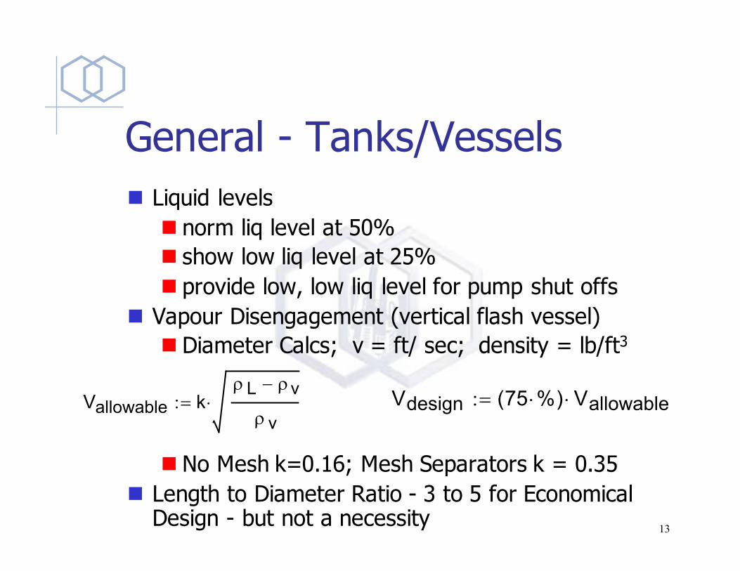
General - Tanks/Vessels
� Liquid levels
� norm liq level at 50%
� show low liq level at 25%
� provide low, low liq level for pump shut offs
� Vapour Disengagement (vertical flash vessel)
� Diameter Calcs; v = ft/ sec; density = lb/ft3
� No Mesh k=0.16; Mesh Separators k = 0.35
� Length to Diameter Ratio - 3 to 5 for Economical Design - but not a necessity
Vallowable kρL ρv−
ρ v⋅:= Vdesign 75 %⋅( ) Vallowable⋅:=
13

Mesh Separator

Codes Stds’ - ASME
�ASME - American Society of Mechanical Engineers
�Section I - Fired Heaters
�Section VIII - Pressure Vessels
�Other Sections (Plastic / Fiberglass /
nuclear)
14

Auxiliaries
�Manholes / inspection ports
�ASME Code has minimum requirements for
these based on vessel size - See Section 8 UG-46
� Nozzles - velocities
�max v=100/√ρ , ft/sec
�min v= 60/√ρ , ft/sec
� Non-tangential inlet for easier level control
14

Auxiliaries
� Thermowells
� Steamouts
�Maintenance blinds
� Drains
� Level Gauges
12 ft
36 inLow Liq Level= 6”
Norm Liq Level = 12”
High Liq Level = 18”
M
V
X
Y U
R
D

Towers
� Diameter - Pro II
� Tray Section Height
�Number of Real Trays
�Ideal Trays / 0.6 * 1.1
�Height = 24” x # trays
�Remember - subtract condenser & Reboiler
� Additional Height for Reboiler
� Additional Height for V/L Separation at top
� Double Tray Spacing at Feed

Towers
6 ft
4 ft
Double Tray
Space
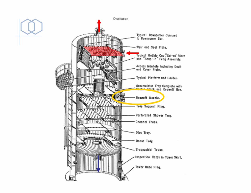
Towers - Diag

Valve Trays

Towers
� Tray Flows
VIDEO

Towers
� Packing
�Random
�Structured

Field Fabricated Vessels/Tanks
� Fabricate in field if shipping is impractical
� Typically large atmospheric tanks
� Tank Types
�Cone,
�floating roof,
�sphere,
�hemispheroid
� Codes & Std’s – API, ASME

Storage Tanks Design Pressures < 15 psig

Tank Farm

Tanks - Cone Roof
� Typically Design Pressure < 2 psig, but usually 2.5 Inches Water gauge
� Ensure Vapour Pressure of Liquid is sufficiently low (suggest < half D.P.)

Storage Tanks - Cone Roof Conservation Vent

Tanks - Floating Roof
� Suitable for fluids with vapour pressures up to about 8 psig
pontoons Edge Seal
Floating Roof

Tanks - Spheres
� Suitable for Design Pressures of
�2 to 15 psig
�30 to 220 psig (Ludwig)

Tanks - Bullet Tanks
� Any Pressure
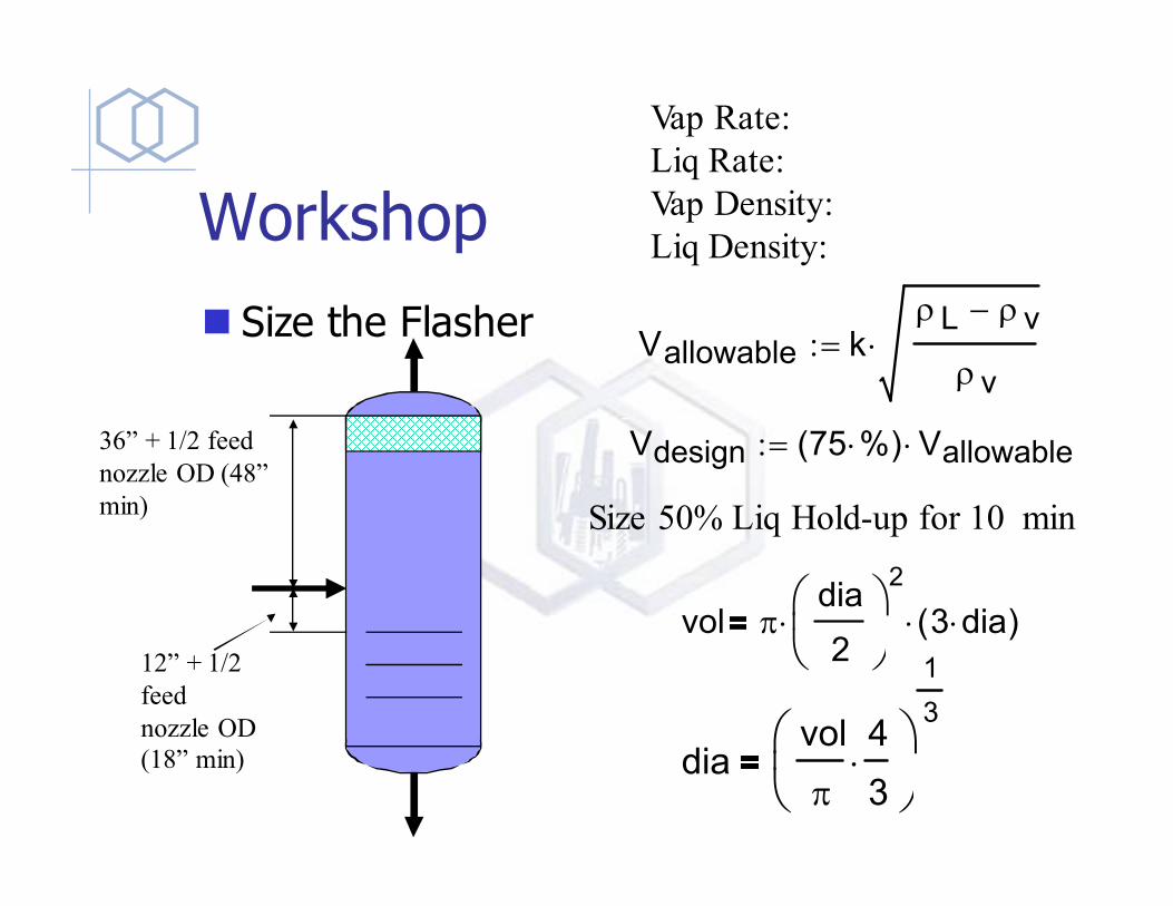
Workshop
vol πdia
2
2
⋅ 3 dia⋅( )⋅
diavol
π
4
3⋅
1
3
Vallowable kρL ρv−
ρv⋅:=
Vdesign 75 %⋅( ) Vallowable⋅:=
� Size the Flasher
Vap Rate:
Liq Rate:
Vap Density:
Liq Density:
Size 50% Liq Hold-up for 10 min
36” + 1/2 feed
nozzle OD (48”
min)
12” + 1/2
feed
nozzle OD
(18” min)
end

questions
� types of trays
� horiz vs vertical reactors
� lifter roof?
�Margin of error on flows
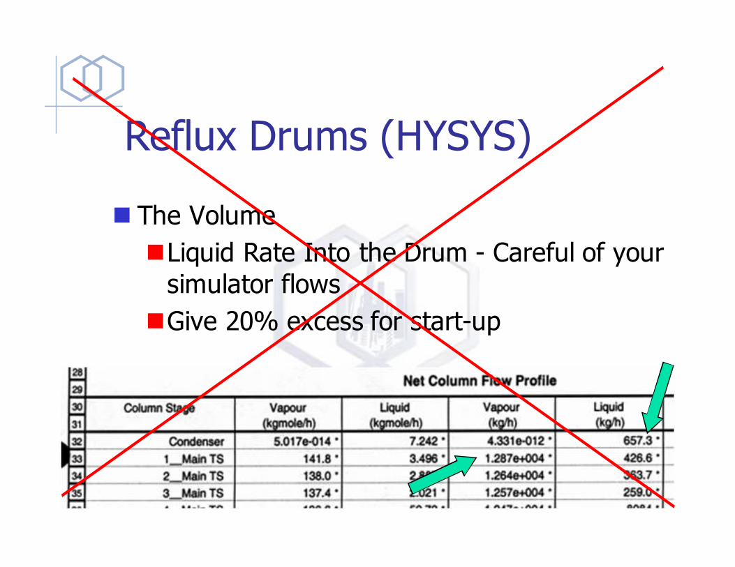
Reflux Drums (HYSYS)
� The Volume
�Liquid Rate Into the Drum - Careful of your
simulator flows
�Give 20% excess for start-up


