
DOOR SECURITY SYSTEM USING E-KTP READING AND
PASSIVE INFRARED SENSOR
A final project report
presented to
the Faculty of Engineering
By
Mohammad Adrian Faisal
002201100012
in partial fulfillment
of the requirements of the degree
Bachelor of Science in Electrical Engineering
President University
January 2015

President University i
DECLARATION OF ORIGINALITY
I declare that this final project report, entitled “Door Security System Using e-KTP
Reading and Passive Infrared Sensor” is my own original piece of work and, to the best of
my knowledge and belief, has not been submitted, either in whole or in part, to another
university to obtain a degree. All sources that are quoted or referred to are truly declared.
Cikarang, Indonesia, January 2015
Mohammad Adrian Faisal

President University ii
APPROVAL PAGE
DOOR SECURITY SYSTEM USING E-KTP READING AND
PASSIVE INFRARED SENSOR
By
Mohammad Adrian Faisal
002201100012
Approved by
Dr.-Ing. Erwin Sitompul, M.Sc, Dr.-Ing. Erwin Sitompul, M.Sc,
Final Project Supervisor Head of Study Program
Electrical Engineering
Dr.-Ing. Erwin Sitompul, M.Sc,
Acting Dean of Faculty of Engineering

President University iii
ACKNOWLEDGMENT
Alhamdulillahi rabbil ‘alamin, I would like to deliver gratitude to Allah subhanahu
wa ta’ala for blessing, love, opportunity, health, and mercy to complete this final project.
Shalawat is also sent to Prophet Muhammad shallallahu ‘alaihi wa sallam who had
delivered the truth to human beings in general and Muslim in particular.
In arranging this final project, a lot of people have provided motivation, advice and
support me. In this valuable chance, I would like to express my gratitude and appreciation
to all of them. First, my deepest appreciation goes to my beloved parents, Mr. Awaluddin
Djuaeni and Mrs. Anna Cheriana who always give me strength and supports when I need
it. And also for my brother Rizki Rahmawan and sister Ayunita Chaerunissa who always
support me.
I would also thank my final project advisor, Dr.-Ing. Erwin Sitompul, M.Sc
who also acting as the Dean of Faculty Engineering for the precious supervision,
advice, and guidance. I wish to thank all Electrical Engineering lectures for their guidance
since I begin my university life in President University until now.
Last but not least, I would like to thank to many people for all supports that they
give me. For my best partner, Fauziyah Kurniawati, who always gives me supports in
every aspects that I need, for my classmates who give me motivation to do my best, for my
roomates, Fandi, Fikri, and Rayhan who always motivated me and encouraged me, and the
last is for all people that always motivated me and encouraged me, whose name could not
mentioned one by one in this final project, for their valuable assistance to me.
Cikarang, January 2015,
Mohammad Adrian Faisal

President University iv
APPROVAL FOR SCIENTIFIC PUBLICATION
I hereby, for the purpose of development of science and technology, certify and approve to
give President University a non-exclusive royalty-free right upon my final project report
with the title:
DOOR SECURITY SYSTEM USING E-KTP READING AND PASSIVE
INFRARED SENSOR
along with the related software or hardware prototype (if needed). With this non-exclusive
royalty-free right, President University is entitled to conserve, to convert, to manage in a
database, to maintain, and to publish my final project report. These are to be done with the
obligation from President University to mention my name as the copyright owner of my
final project report.
Cikarang, 27 January 2015
Mohammad Adrian Faisal
002201100012
President University v
ABSTRACT
A door is meant to be the legitimate access to come into a room. Along the time, there are
some alternatives for door lock, such as electric door lock. Radio Frequency Identification
(RFID) is the new technology that can be used to improve the security system of an electric
door lock. An RFID system needs an RFID reader, an RFID tag, and a computer
/microcontroller in order to make it work properly. Indonesian identity card (e-KTP) with
contactless smart card technology can be used as the tag of the RFID. Every e-KTP has
unique ID stored in the chip. This final project concentrates in designing a prototype of
electric door lock system that will work as an integrated system of electric door lock,
equipped with RFID technology with e-KTP as the key. Besides, the system is also
equipped with a passive infrared sensor to detect unauthorized presence. The developed
prototype proved the feasibility of installing a reliable door security system using e-KTP as
the key and passive infrared sensor as additional security measure.
Keywords: electric lock, RFID technology, e-KTP, passive infrared sensor.

President University vi
TABLE OF CONTENT
DECLARATION OF ORIGINALITY ................................................................................... i
APPROVAL PAGE ............................................................................................................... ii
ACKNOWLEDGMENT ...................................................................................................... iii
APPROVAL FOR SCIENTIFIC PUBLICATION .............................................................. iv
ABSTRACT .......................................................................................................................... v
TABLE OF CONTENT ....................................................................................................... vi
LIST OF FIGURES ............................................................................................................ viii
LIST OF TABLES ................................................................................................................ x
CHAPTER 1 INTRODUCTION ........................................................................................... 1
1.1. Final Project Background ........................................................................................ 1
1.2. Problem Statement .................................................................................................. 2
1.3. Final Project Objectives .......................................................................................... 2
1.4. Final Project Scopes and Limitations ...................................................................... 3
1.5. Final Project Outline ............................................................................................... 3
CHAPTER 2 DESIGN SPECIFICATION ............................................................................ 5
2.1. Introductory Remarks .............................................................................................. 5
2.2. Arduino Mega 2560................................................................................................. 5
2.2.1. Serial Peripheral Interface (SPI) .................................................................... 8
2.2.2. Arduino IDE .................................................................................................. 9
2.3. Radio Frequency Identification (RFID) ................................................................ 10
2.3.1 RFID tag ....................................................................................................... 11
2.3.1.1 Passive RFID tag ................................................................................. 12
2.3.1.2 Active RFID tag .................................................................................. 12
2.3.1.3 Semi Passive RFID tag ........................................................................ 13
2.3.2 RFID reader .................................................................................................. 13
2.3.3 Operating frequency of RFID system ........................................................... 15
2.3.4 How RFID system works ............................................................................. 16

President University vii
2.4. MFRC522 .............................................................................................................. 17
2.5. e-KTP .................................................................................................................. 18
2.6. Liquid Crystal Display (LCD) ............................................................................... 20
2.7. PIR Sensor (Passive Infrared Sensor) ................................................................... 22
2.8. 12 V Relay ............................................................................................................. 24
2.9. Solenoid Door Lock .............................................................................................. 26
2.10. Transistor TIP122................................................................................................. 27
2.11. Voltage Regulator LM 7812 ................................................................................ 27
2.12. Digital Buzzer Module ......................................................................................... 28
2.13. Push Button .......................................................................................................... 30
2.14. AC/DC Adaptor ................................................................................................... 30
2.15. Accumulator ......................................................................................................... 31
CHAPTER 3 DESIGN IMPLEMENTATION ................................................................... 32
3.1. System Overview .................................................................................................. 32
3.2. Hardware Implementation ..................................................................................... 33
3.2.1. RFID reader (MFRC522) implementation .................................................. 33
3.2.2. LCD 16x2 implementation .......................................................................... 34
3.2.3. PIR Sensor. digital buzzer module, and push button implementation ........ 36
3.2.4. Solenoid door lock and power circuit implementation ................................ 37
3.3. Programming Implementation ............................................................................... 38
3.3.1. Arduino programming ................................................................................. 38
3.3.2. Main programming code ............................................................................. 39
CHAPTER 4 RESULTS AND DISCUSSION ................................................................... 45
4.1. Results .................................................................................................................. 45
4.2. Discussion ............................................................................................................. 50
CHAPTER 5 CONCLUSSION ........................................................................................... 51
5.1. Conclusions ........................................................................................................... 51
5.2. Recommendations ................................................................................................. 51
REFERENCES .................................................................................................................... 53
APPENDIX A SOURCE CODE ......................................................................................... 55

President University viii
LIST OF FIGURES
Figure 2.1 Arduino Mega 2560 [1] ....................................................................................... 5
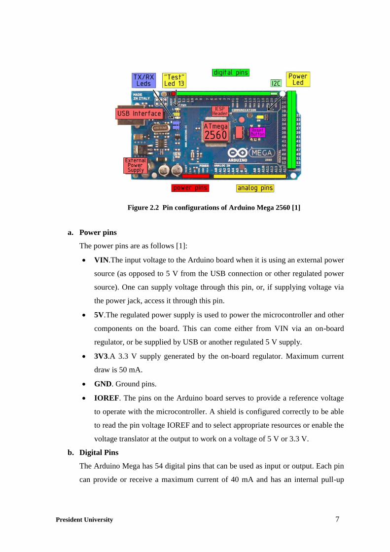
Figure 2.2 Pin configurations of Arduino Mega 2560 [1] .................................................... 7
Figure 2.3 Arduino IDE interface ....................................................................................... 10
Figure 2.4 RFID system [4] ................................................................................................ 11
Figure 2.5 Inductively coupled tag with antenna coil [4] .................................................... 11
Figure 2.6 Passive RFID tag [5] ......................................................................................... 12
Figure 2.7 Active RFID tag [5] .......................................................................................... 13
Figure 2.8 Semi Passive RFID tag [5] ................................................................................. 13
Figure 2.9 Block function of RFID reader [4] ..................................................................... 14
Figure 2.10 Block diagram of an RF interface for an inductively coupled RFID [5] ......... 15
Figure 2.11 Power supply to an inductively coupled tag from the energy of the magnetic
alternating field generated by the reader [4] ................................................... 16
Figure 2.12 Schematic depiction of Inside passive RFID tag [5] ........................................ 17
Figure 2.13 MFRC522 ......................................................................................................... 17
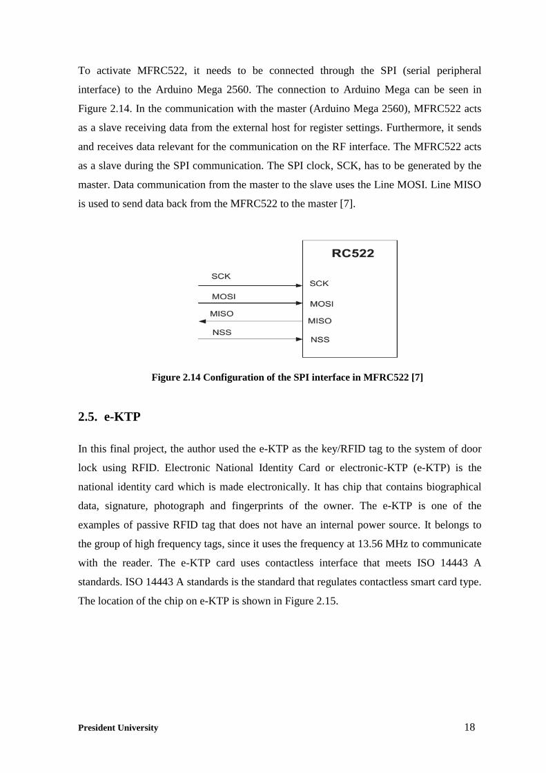
Figure 2.14 Configuration of the SPI interface in MFRC522 [7] ....................................... 18
Figure 2.15 Physical form of e-KTP [8] .............................................................................. 19
Figure 2.16 The unique ID of e-KTP read by MFRC522 ................................................... 19
Figure 2.17 Layer of e-KTP card [8] ................................................................................... 19
Figure 2.18 LCD 16x2 ......................................................................................................... 20
Figure 2.19 PIR sensor [10] ................................................................................................. 22
Figure 2.20 Pin configurations of PIR sensor [10] .............................................................. 23
Figure 2.21 PIR sensor block diagram [11] ......................................................................... 24
Figure 2.22 12V Relay ........................................................................................................ 24
Figure 2.23 Relay pin explanation ....................................................................................... 24
Figure 2.24 Parts of the relay [12] ....................................................................................... 25
Figure 2.25 Solenoid door lock ........................................................................................... 26
Figure 2.26 Pin configurations of transistor TIP122 [15] ................................................... 27
Figure 2.27 Pin configurations of LM 7812 [16] ................................................................ 28
Figure 2.28 Application circuit for LM 7812 ...................................................................... 28
President University ix
Figure 2.29 Digital buzzer module from DFRobot [17] ...................................................... 29
Figure 2.30 Pin configuration of digital buzzer module [17] .............................................. 29
Figure 2.31 Push button ....................................................................................................... 30
Figure 2.32 Application circuit for push button .................................................................. 30
Figure 2.33 AC/DC adaptor ................................................................................................ 31
Figure 2.34 Accumulator ..................................................................................................... 31
Figure 3.1 Block diagram of the system .............................................................................. 32
Figure 3.2 Pin configurations of RFID reader (MFRC522) ................................................ 34
Figure 3.3 Pin configurations of LCD 2x16 ........................................................................ 35
Figure 3.4 Pin configurations of PIR sensor, digital buzzer module, Push Button 1,
and Push Button 2 ............................................................................................ 36
Figure 3.5 Pin configurations of solenoid door lock and power circuit ............................. 38
Figure 3.6 Flow chart of electric lock part .......................................................................... 43
Figure 3.7 Flow chart of sensor part .................................................................................... 44
Figure 4.1 Front view of the automatic door ....................................................................... 45
Figure 4.2 The automatic door (a) Back view; (b) Left view .............................................. 46
Figure 4.3 Main hardware of the system ............................................................................. 47
Figure 4.4 Top view of automatic door ............................................................................... 47
Figure 4.5 “Calibrating PIR for 10 s message displays on LCD ......................................... 48
Figure 4.6 “Welcome Waiting e-KTP” message displays on LCD ..................................... 48
Figure 4.7 “Valid” Message to user 1 (left) and to user 2 (right) ........................................ 48
Figure 4.8 “e-KTP Not valid Shall not Pass!!” message displays on LCD ........................ 49
Figure 4.9 Solenoid door lock (a) Open State; (b) Close State ........................................... 49
Figure 5.1 Door closer ......................................................................................................... 52
Figure 5.2 Automatic accumulator charger ......................................................................... 52

President University x
LIST OF TABLES
Table 2.1 Arduino Mega 2560 Specification ....................................................................... 6
Table 2.2 LCD Pin Function .............................................................................................. 20
Table 2.3 LCD Bit Configurations ..................................................................................... 21
Table 2.4 LCD Function ..................................................................................................... 22
Table 2.5 Pin Function of PIR Sensor ................................................................................ 23
Table 2.6 12 V Relay Specifications .................................................................................. 25
Table 2.7 Specification of Solenoid Door Lock ................................................................. 26
Table 3.1 Pin Configurations of RFID reader (MFRC522)................................................ 34
Table 3.2 Pin Configurations of LCD 16x3 ....................................................................... 35
Table 3.3 The Code Explanation of Electric Lock Part ...................................................... 39
Table 3.4 The Code Explanation of Sensor Part ................................................................ 41
Table 3.5 Display message on LCD ................................................................................... 42

President University 1
CHAPTER 1
INTRODUCTION
1.1. Final Project Background
A door has the function as an entrance into a room, a building, or a vehicle. In the market,
there are 2 kinds of door lock, which are electric lock and mechanic lock. An electric lock
is a locking device which operates by using force from electricity. Electric locks are
connected to an access system that will make an automatic locking system. On the other
hand, a mechanic lock is operated by mechanical force and does not operate automatically.
It means, in order to lock or unlock the mechanic lock, a regular key must be manually
used.
Nowadays, people prefer the use of an electric lock compared to a mechanic lock. This is
because an electric lock has a more complex security system than a mechanic lock. Electric
locks offer a variety of means of authentication, including: numerical codes, passwords,
passphrases, security tokens, biometrics, and RFID (Radio-frequency identification). This
means, an electric lock has a system which is more secure and uneasy to break. The
mechanic lock itself has a system which is less secure because the less and limited number
of key combinations.
The e-KTP (Indonesian: Kartu Tanda Penduduk Elektronik) was introduced by the
Indonesian Ministry for Internal Affairs in February 2011 to replace the then existing
identity card. The e-KTP is an identity card for Indonesian citizen in which the data of the
card holder are electronically stored, not physically. The data storage process is fully
computerized and the data is very hard to duplicate. Until now, e-KTP is only used as an
identity card. Whereas, e-KTP actually includes a kind of smart card with the data that can
be used for public transportation, health service, access token, etc. Access token itself is an
object used to access the system, such as electric lock system for a door. The e-KTP card
uses RFID technology that operates at the frequency of 13.56 MHz. An RFID reader is
required to read it. Thus, e-KTP card, along with RFID reader, can function as a key that
will give access to a door.

President University 2
1.2. Problem Statement
The final project will mainly focus on designing the hardware that will work as an
integrated system of electric door lock, equipped with an RFID reader. This electric door
can be locked or unlocked automatically. To control this hardware, we need to use a
microcontroller and to design the software, so that the door can work according to the
command. Commands are given to the microcontroller by using C/C++ programming. This
is to coordinate all components in this final project.
Every e-KTP has a unique ID. Unique ID from e-KTP has 7 byte data. We need to use an
RFID reader and a microcontroller to read an e-KTP, along with the use of provided library
on designing the program. This program is needed to make the RFID reader be able to
work and be able to read the e-KTP. We also need to design the circuit which will be
integrated to the RFID reader and the microcontroller.
Later on, we can save the unique ID of the e-KTP to the microcontroller. Thus, only the
person with authorized right is able to open the door. In order to operate the electric lock,
we can just simply move an authorized e-KTP close to an RFID reader and the door will
unlock before it automatically lock again after a certain period of time.
1.3. Final Project Objectives
The objective of this final project is to make a device that can improve the security of a
door lock system and at the same time to make the way to unlock door easier and faster.
By making this device, the author expects to achieve the following objectives:
1. To design an automatic door lock system that implements the RIFD technology and
RFID system which is able to use an e-KTP as the key.
2. To additionally implement PIR (Passive Infrared) sensor to detect the presence of
human when passing the door. This will provide additional security in case the door
is breached.

President University 3
1.4. Final Project Scopes and Limitations
In doing this final project, there will be exact scope and limitations. Because of the time
and resources are limited, the final project will be conducted under the following scopes:
This final project will discuss and present the making of an electric door lock
system with RFID reader by using several components such as Arduino Mega
2560, MFRC522 (RFID reader), solenoid door lock, LED, PIR (Passive Infrared)
sensor, buzzer, resistor, transistor and LCD.
The software used is Arduino IDE 1.06, featured by Arduino. Arduino IDE 1.06
uses C programming language to operate. It provides some libraries which are
needed in the programming in order to make the MFRC522 (RFID reader) and the
LCD 16x2 work properly.
In conducting this project, there are several limitations to be considered:
The RFID reader is used to read the unique ID of e-KTP and to send it to Arduino
Mega for further process. If the unique ID of e-KTP is identical with the ID that has
been stored in Arduino, the door will be unlocked.
The RFID reader is only programmed to be able to read passive tags, which are tags
without energy source.
The frequency range used for RFID reader is 13.56 MHz (high frequency).
The transistor is used as switch to control the solenoid door lock.
The PIR sensor is used only to detect the presence of human.
1.5. Final Project Outline
The final project report consists of five chapters and is outlined as follows:
Chapter 1: Introduction. This chapter consists of Final Project Background, Problem
Statement, Final Project Objectives, Final Project Scopes and Limitations,
and Final Project Outline.
Chapter 2: Design Specification. This chapter describes the proposed design of the
automatic door lock system by the author. It also gives the information about
the list of the hardware and the software used in this project along with their

President University 4
functions. This chapter also discusses how the circuit system works and how
the interfacing among the hardware components is to be done. In this
chapter, the author also will explain about the theory that is used in this final
project.
Chapter 3: Design Implementation. This chapter will deliver the implementation of the
design presented in the previous chapter. It covers system design, system
flow, hardware and software configuration, and resource requirement.
Chapter 4: Project Result and Discussion. This chapter consists of the result of the project.
In this chapter also consist of discussion about the result of the project.
Chapter 5: Conclusions and Recommendations. This chapter consists of conclusions of the
whole content of the final project report. Recommendations are presented in
order to make developments and improvements in the future.

President University 5
CHAPTER 2
DESIGN SPECIFICATION
2.1. Introductory Remarks
This chapter will explain the theory of the hardware and the software that are used to make
the device in this project. Each of the hardware and the software has different operation
method and different usage. Because of that, it is very important to understand the basic of
the technology used inside it. At following section, the author will explain concept of
technology that is used as the basic of the making of the electric lock door using RFID.
2.2. Arduino Mega 2560
The Arduino Mega 2560, as shown in Figure 2.1, is a microcontroller board based on the
Atmel AVR ATmega2560 Microcontroller. It has 54 digital input/output pins (of which 14
can be used as PWM outputs), 16 analog inputs, 4 UARTs (hardware serial ports), a 16
MHz crystal oscillator, a USB connection, a power jack, an ICSP header, and a reset
button. It contains everything needed to support the microcontroller; simply connect it to a
computer with a USB cable or power it with an AC-to-DC adapter or battery to get started
[1].
Figure 2.1 Arduino Mega 2560 [1]

President University 6
The Arduino Mega2560 can be powered via the USB connection or with an external power
supply. The power source is selected automatically. External (non-USB) power can come
either from an AC-to-DC adapter (wall-wart) or battery. The adapter can be connected by
plugging a 2.1mm center-positive plug into the board's power jack. Leads from a battery
can be inserted in the GND and VIN pin headers of the POWER connector. The
specification of Arduino Mega 2560 can be seen in Table 2.1 [1].
Table 2.1 Arduino Mega 2560 Specification
Microcontroller ATmega2560
Operating Voltage 5 V
Input Voltage (recommended) 7-12 V
Input Voltage (limits) 6-20 V
Digital I/O Pins 54 (of which 14 provide PWM output)
Analog Input Pins 16
DC Current per I/O Pin 40 mA
DC Current for 3.3V Pin 50 mA
Flash Memory 256 KB of which 8 KB used by bootloader
SRAM 8 KB
EEPROM 4 KB
Clock Speed 16 MHz
The board can operate on an external supply of 6 to 20 V. If supplied with less than 7 V,
however, the 5 V pin may supply less than five volts and the board may be unstable. If
using more than 12 V, the voltage regulator may overheat and damage the board. The
recommended range is 7 to 12 V.
The Arduino Mega has many pin configurations. Each of them has different characteristic
and function. These pin configurations are divided into several part of characters. There are
power pins, digital pins and analog pins. Here are the descriptions of the pin configurations
based on Figure 2.2:
President University 7
a. Power pins
The power pins are as follows [1]:
VIN.The input voltage to the Arduino board when it is using an external power
source (as opposed to 5 V from the USB connection or other regulated power
source). One can supply voltage through this pin, or, if supplying voltage via
the power jack, access it through this pin.
5V.The regulated power supply is used to power the microcontroller and other
components on the board. This can come either from VIN via an on-board
regulator, or be supplied by USB or another regulated 5 V supply.
3V3.A 3.3 V supply generated by the on-board regulator. Maximum current
draw is 50 mA.
GND. Ground pins.
IOREF. The pins on the Arduino board serves to provide a reference voltage
to operate with the microcontroller. A shield is configured correctly to be able
to read the pin voltage IOREF and to select appropriate resources or enable the
voltage translator at the output to work on a voltage of 5 V or 3.3 V.
b. Digital Pins
The Arduino Mega has 54 digital pins that can be used as input or output. Each pin
can provide or receive a maximum current of 40 mA and has an internal pull-up
Figure 2.2 Pin configurations of Arduino Mega 2560 [1]

President University 8
resistor (disconnected by default) of 20-50 kΩ. In addition, some pins have
specialized functions, which include [1]:
Serial: 0 (RX) and 1 (TX); Serial 1: 19 (RX) and 18 (TX); Serial 2: 17 (RX)
and 16 (TX); Serial 3: 15 (RX) and 14 (TX). Used to receive (RX) and
transmit (TX) TTL serial data. Pins 0 and 1 are also connected to the
corresponding pins of the ATmega8U2 USB-to-TTL Serial chip.
External Interrupts: 2 (interrupt 0), 3 (interrupt 1), 18 (interrupt 5), 19
(interrupt 4), 20 (interrupt 3), and 21 (interrupt 2). These pins can be
configured to trigger an interrupt on a low value, a rising or falling edge, or a
change in value.
PWM: 0 to 13. Provide 8-bit PWM output with the analogWrite()function.
SPI: 50 (MISO), 51 (MOSI), 52 (SCK), 53 (SS). These pins support SPI
communication, which, although provided by the underlying hardware, is not
currently included in the Arduino language. The SPI pins are also broken out
on the ICSP header.
LED: 13.There is a built-in LED connected to digital pin 13. When the pin is
HIGH value, the LED is on, when the pin is LOW, it is off.
I2C: 20 (SDA) and 21 (SCL). Support I2C (TWI) communication using the
Wire library (documentation on the Wiring website).
c. Analog Pins
The Arduino Mega 2560 has 16 analog inputs, each of which provides 10 bits of
resolution. By default they measure from ground to 5 V, though is it possible to
change the upper end of their range using the AREF pin and analogReference()
function. There are a couple of other pins on the board [1]:
AREF. Reference voltage for the analog inputs. Used with analogReference().
Reset. Bring this line LOW to reset the microcontroller. Typically used to add
a reset button to shields which block the one on the board.
2.2.1. Serial Peripheral Interface (SPI)
SPI (serial peripheral interface) is a synchronous serial data protocol used by
microcontrollers for communicating with one or more peripheral devices quickly over
short distances. It can also be used for communication between two microcontrollers. With

President University 9
an SPI connection there is always one master device (usually a microcontroller) which
controls the peripheral devices [2]. Typically there are four pins common to all the devices:
1. MISO (Master In Slave Out) : Arduino digital pin 50 - The Slave line for sending data
to the master,
2. MOSI (Master Out Slave In) : Arduino digital pin 51 - The Master line for sending
data to the peripherals,
3. SCK (Serial Clock) : Arduino digital pin 52 - The clock pulses which synchronize
data transmission generated by the master and one line specific for every device:
4. SS (Slave Select): Arduino digital pin 53 - the pin on each device that the master can
use to enable and disable specific devices.
When a device's Slave Select pin is low, it communicates with the master. When it is high,
it ignores the master. This allows us to have multiple SPI devices sharing the same MISO,
MOSI, and CLK pins.
2.2.2. Arduino IDE
The Arduino IDE (integrated development environment), as shown in Figure 2.3, is the
software used for the programming the Arduino Board. It includes a code editor with
features such as syntax highlighting, brace matching, and automatic indentation, and is also
capable of compiling and uploading programs to the board with a single click. A program
or code written for Arduino is called a sketch [3].
Arduino programs are written in C or C++. The Arduino IDE comes with a software
library called "Wiring" from the original Wiring project, which makes many common
input/output operations much easier. Users only need define two functions to make a
runnable cyclic executive program:
setup(): a function run once at the start of a program that can initialize settings
loop(): a function called repeatedly until the board powers off

President University 10
2.3. Radio Frequency Identification (RFID)
RFID (Radio Frequency Identification) is the wireless use of electromagnetic fields to
transfer data, for the purposes of automatically identifying and tracking tags attached to
objects/reader. As shown in Figure 2.4, RFID system consists of two main components,
which include:
a. Tag, which consist of coupling element and electronic microchip.
b. Reader, which usually consists of radio frequency module (transmitter and
receiver), controller, and coupling element to the tag.
c. Computer/microcontroller, which is connected to the reader.
Figure 2.3 Arduino IDE interface

President University 11
RFID technology is the answer to various weaknesses of the barcode technology because it
can only be identified by means of the barcode closer to a reader. Barcode also has very
limited data storage capacity and cannot be re-programmed, making it difficult to store and
update the data in large quantities for an item. One of interesting solution that emerged is
storing data on a silicon chip. This technology is known as RFID. Contact between the
RFID tag to the reader is not done through physical or mechanical contact but merely by
transmitting electromagnetic signals (contactless).
2.3.1 RFID tag
RFID tags, or simply "tags", are small transponders that respond to queries from a reader
by wirelessly transmitting a serial number or similar identifier [6]. The basic layout of the
RFID tag can be seen in Figure 2.5.
Figure 2.4 RFID system [4]
Figure 2.5 Inductively coupled tag with antenna coil [4]

President University 12
2.3.1.1 Passive RFID tag
The passive tags, as shown in Figure 2.6, do not have an internal power source. To power
the tag, the reader need to induce power to the tag. This means that the reader has to keep
up its power field until the transaction is completed. Because of the lack of a battery,
passive tags are the smallest and cheapest tags which are available in the market. In
exchange for this low cost and low energy, the reading range of the tag is very short.
Depending on the type of passive RFID tag, the reading range can be down to 2 cm. The
response of a passive RFID usually contains simple information that is encoded in the tag
memory. For example, only the ID number of the tag will be given as a response. Because
the passive RFID does not need a battery, the size of the tag can be made smaller. Through
the small size, the RFID tag can be attached to any item. For example, card, key chain,
mobile phone, etc.
2.3.1.2 Active RFID tag
An active RFID tag, as shown in Figure 2.7, has its own power supply which can be used
in part or in whole tag. The power supply enables the circuit microchip and an antenna to
send a signal to the reader. Some active RFID tags can also be connected to an external
power supply. This kind of active tag has longer working range compared to passive tags.
Mostly it has larger memory which can keep more amounts of data.
Figure 2.6 Passive RFID tag [5]

President University 13
To avoid the continuous use of the battery that will shorten the battery life, an active RFID
tag has a microchip that can regulate the operation of the tag. When the tag is out of the
reader’s range, the microchip will automatically set the tag to a state of "power down"
mode or "stand-by" to save power.
2.3.1.3 Semi Passive RFID tag
A semi passive RFID tag, as shown in Figure 2.8, is nearly the same as an active RFID tag.
This tag also has its own power supply, but the power supply is only used to activate the
microchip and antenna, not to be used to send signals to the reader. To process a
broadcasted signal, the method used is the same as in the case of passive RFID tag.
2.3.2 RFID reader
A reader is a component identifier in an RFID system. The technology used allows the
reader to trace and identify the presence of tags. A Reader can be divided into two blocks
of functionality [4], as shown in Figure 2.9.
Figure 2.7 Active RFID tag [5]
Figure 2.8 Semi Passive RFID tag [5]

President University 14
Two functions of the blocks are:
a. HF interface
High Frequency interface is used by the reader to produce a transmission signal to
activate the tag and the power supply for passive tag, to modulate the signal transmitted
to the tag, and to demodulate the signal received from a tag. HF interface consists of
two separate signal paths, based on the two-way flow of data, from the tag and to tag,
as shown in Figure 2.10. The data sent to the tag will go through the transmitter and the
data received from the tag will be processed at the receiver [4].
First, a signal of the required operating frequency, i.e. 135 kHz or 13.56 MHz, is
generated in the transmitter arm by a stable (frequency) quartz oscillator. To avoid
worsening the noise ratio in relation to the extremely weak received signal from the
transponder, the oscillator is subject to high demands regarding phase stability and
sideband noise. The oscillator signal is fed into a modulation module controlled by the
baseband signal of the signal coding system [4].
The modulated signal is then brought to the required level by a power output module
and can then be decoupled to the antenna box. The receiver arm begins at the antenna
box, with the first component being a steep edge bandpass filter. The filter has the task
of largely blocking the strong signal from the transmission output module and filtering
out just the response signal from the transponder [4].
Figure 2.9 Block function of RFID reader [4]

President University 15
b. Control system
Part on the reader controller, performs the following functions [4]:
Communication with the application software and the execution of commands
from the application software;
Control of the communication with a transponder (master –slave principle);
Signal coding and decoding.
The control unit is usually based upon a microprocessor to perform these complex
functions. Data exchange between application software and the reader’s control
unit is performed by a serial peripheral interface [4].
2.3.3 Operating frequency of RFID system
Because an RFID generates and radiates electromagnetic field, then the system containing
it is classified as a radio system. Thus, the frequency used by the RFID system should not
interfere with the frequencies used by television, radio and other services [6]. RFID tags
fall into three regions in respect to frequency:
a. Low frequency tag (125 to 134 kHz)
b. High frequency tag (13.56 MHz)
c. Ultra high frequency tag (868 to 956 MHz, 2.4 - 2.5GHz, 5.8GHz))
Figure 2.10 Block diagram of an RF interface for an inductively coupled RFID [5]

President University 16
2.3.4 How RFID system works
The supply of power from the reader to the tag occurs when using passive tags. This power
transfer process depends on the use of RFID systems. This report will explains the process
of the signal transmission using inductive coupling. Generally, inductive coupling operates
in passive tags, consists of a single microchip and a wide area as an antenna coil. The
system is generally shown in Figure 2.11. Here, all the power to activate the microchip will
be provided by the reader. The reader antenna will generate strong electromagnetic fields
(high frequency) and will penetrate the area around the coil. Most fields will penetrate the
coil on the tag. This generates a voltage on the tag antenna as a result of the induction
process.
Inside the passive tag, as shown in Figure 2.12, the voltage generated by the reader is
rectified by a diode, and the resulting signal is smoothed using a storage capacitor to create
a more-or-less constant voltage that is then used to power the tag’s logic circuitry and
memory access. A similar rectification circuit, using a smaller capacitance value to allow
the voltage to vary on the timescale of the reader data, is used to demodulate the
information from the reader. This technique is known as envelope detection [5].
Finally, to transmit the information back to the reader, the tag changes the electrical
characteristics of the antenna structure so as to modify the signal reflected from it,
somewhat analogous to tilting a mirror. Here we have shown a field-effect transistor (FET)
used as a switch; when the FET is turned on, the antenna is grounded, allowing a large
current to flow, and when it is off, the antenna floats allowing very little antenna current
[5].
Figure 2.11 Power supply to an inductively coupled tag from the energy of
the magnetic alternating field generated by the reader [4]

President University 17
2.4. MFRC522
The RFID reader used in this project is MFRC522 that can be seen in Figure 2.13.
MFRC522 supports ISO 14443A and contactless communication at 13.56 MHz [7]. The
standard of MFRC522 meets the reader requirement of the e-KTP. Thus, the reader can
read the e-KTP card. The MFRC522’s internal transmitter part is able to drive a
reader/writer antenna designed to communicate with ISO/IEC 14443A cards and
transponders without additional active circuitry.
Figure 2.13 MFRC522
Figure 2.12 Schematic depiction of Inside passive RFID tag [5]
President University 18
To activate MFRC522, it needs to be connected through the SPI (serial peripheral
interface) to the Arduino Mega 2560. The connection to Arduino Mega can be seen in
Figure 2.14. In the communication with the master (Arduino Mega 2560), MFRC522 acts
as a slave receiving data from the external host for register settings. Furthermore, it sends
and receives data relevant for the communication on the RF interface. The MFRC522 acts
as a slave during the SPI communication. The SPI clock, SCK, has to be generated by the
master. Data communication from the master to the slave uses the Line MOSI. Line MISO
is used to send data back from the MFRC522 to the master [7].
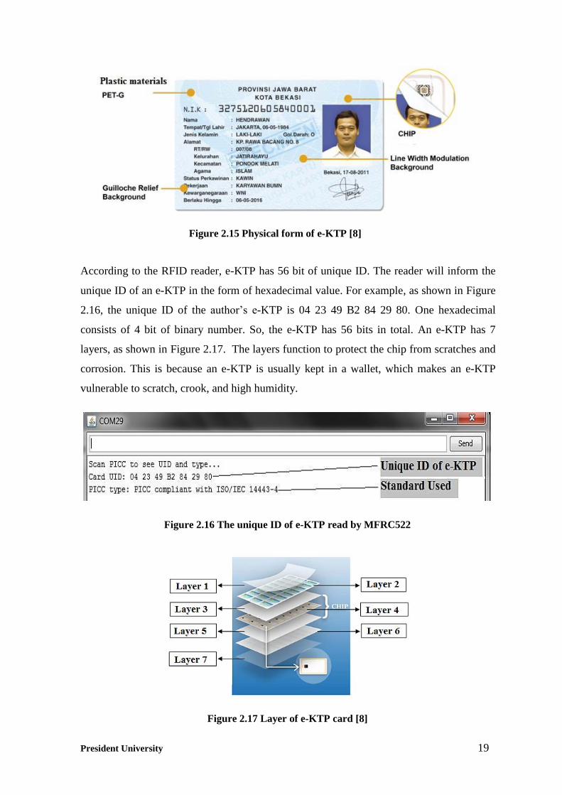
2.5. e-KTP
In this final project, the author used the e-KTP as the key/RFID tag to the system of door
lock using RFID. Electronic National Identity Card or electronic-KTP (e-KTP) is the
national identity card which is made electronically. It has chip that contains biographical
data, signature, photograph and fingerprints of the owner. The e-KTP is one of the
examples of passive RFID tag that does not have an internal power source. It belongs to
the group of high frequency tags, since it uses the frequency at 13.56 MHz to communicate
with the reader. The e-KTP card uses contactless interface that meets ISO 14443 A
standards. ISO 14443 A standards is the standard that regulates contactless smart card type.
The location of the chip on e-KTP is shown in Figure 2.15.
Figure 2.14 Configuration of the SPI interface in MFRC522 [7]
President University 19
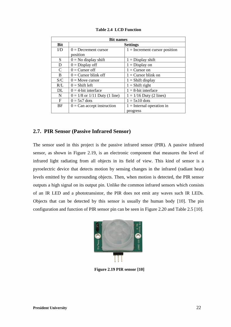
According to the RFID reader, e-KTP has 56 bit of unique ID. The reader will inform the
unique ID of an e-KTP in the form of hexadecimal value. For example, as shown in Figure
2.16, the unique ID of the author’s e-KTP is 04 23 49 B2 84 29 80. One hexadecimal
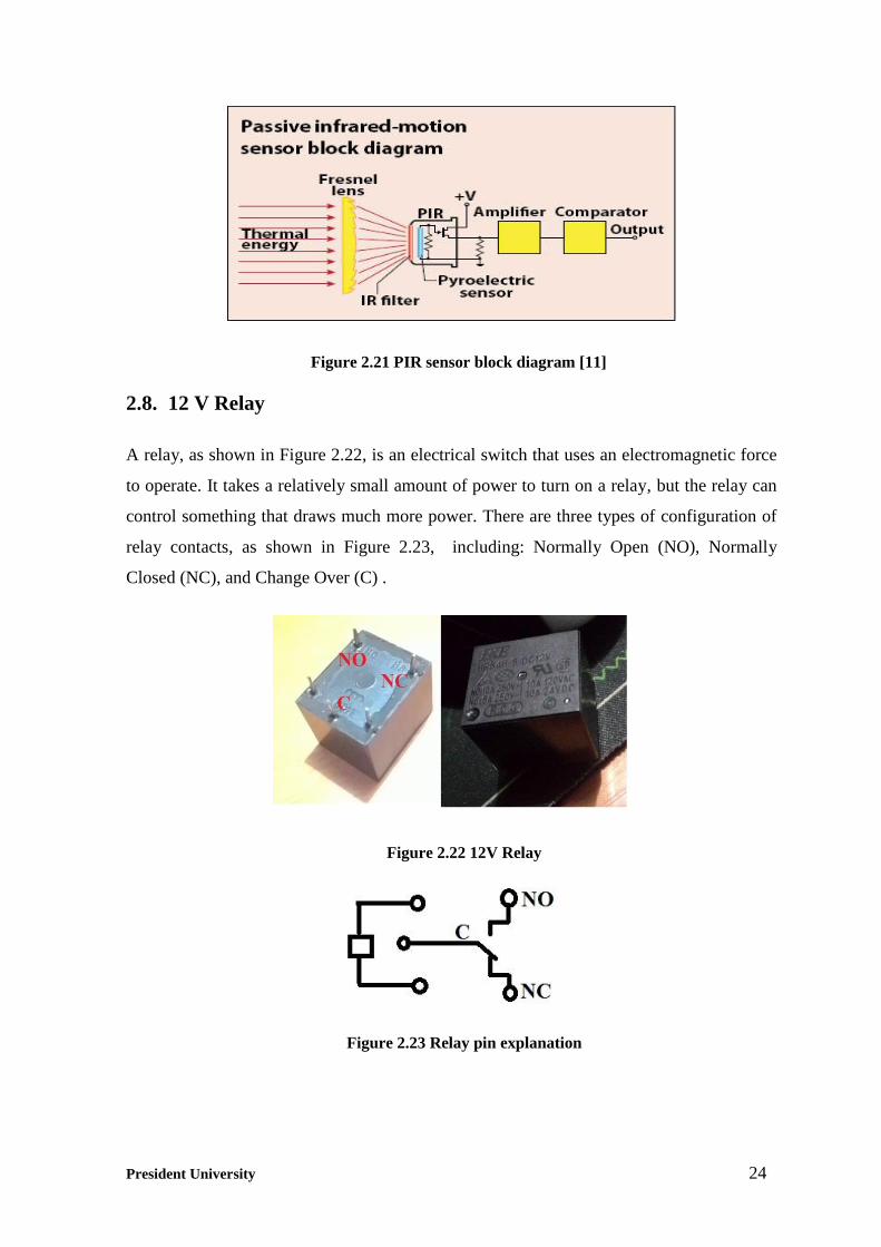
consists of 4 bit of binary number. So, the e-KTP has 56 bits in total. An e-KTP has 7
layers, as shown in Figure 2.17. The layers function to protect the chip from scratches and
corrosion. This is because an e-KTP is usually kept in a wallet, which makes an e-KTP
vulnerable to scratch, crook, and high humidity.
Figure 2.15 Physical form of e-KTP [8]
Figure 2.16 The unique ID of e-KTP read by MFRC522
Figure 2.17 Layer of e-KTP card [8]

President University 20
2.6. Liquid Crystal Display (LCD)
A Liquid Crystal Display (LCD) is an electronic visual display. It is used to show
characters such as numbers or letters, as shown in Figure 2.18. There are two main types of
LCD screen, numerical display (used in watches, calculators, etc.) and alphanumerical
display (often used in mobile phones).
In this project, the author used the LCD 16x2 because it has the capability to display
alphanumerical characters. It requires 3 control pins (RS, R/W, and EN) and 8 (or 4) data
pins. The data pin used can be 8-bit or 4-bits data. The difference between 8-bit data and 4-
bit data is the 8-bit data mode is faster than the 4-bit data mode in processing data from
microcontroller which to be displayed. But, the 4-bit data mode will use less space in the
microcontroller rather than the 8-bit data mode. The explanation of LCD pin is shown in
Table 2.2 [9].
Table 2.2 LCD Pin Function
Pin No Function Name
1 Ground (0V) Ground
2 Supply voltage; 5 V (4.7 V – 5.3 V) VCC
3 Contrast adjustment; through a variable resistor VEE
4 RS = HIGH: to send data
RS = LOW: to send instruction
RS(Register Select)
5 R/W = Low : to write to the register;
R/W = High : to read from the register
R/W (Read/write)
6 Sends data to data pins when a high to low pulse is given EN (Enable)
7 8-bit data pins DB0 – DB7
8 Backlight VCC (5 V) Led+
9 Backlight Ground (0 V) Led-
Figure 2.18 LCD 16x2

President University 21
To use the LCD, first it must be initialized. Initialization is required to choose the
operation mode (8- bit data mode or 4- bit data mode), the number of display lines, and the
character font. As mention above, the LCD 16x2 requires 3 control pins (RS, R/W, and
EN) and 8 (or 4) data pins. EN control pins are used to tell the LCD that the
microcontroller sends the data to it. To send data to the LCD, the program should set EN to
high state (1).
EN must be set to low state (0) to execute the instructions from microcontroller. When the
RS is in low state (0), the data sent to the LCD is considered as a command or special
instructions (such as cleaning the screen, position the cursor, etc.). When the RS is in high
state (1), the data sent to LCD is considered as alphanumerical data. For example, in order
to display letter "A" on the screen, the RS must be set to high state (1). R/W control line
should be in low state (0) when the microcontroller writes the data to the LCD. If the R/W
is in high state (1), then the program will perform a data reading from the LCD.
The display data is stored in Display Data RAM (DDRAM). In order to display
character(s) on the LCD, the DDRAM should be written. The address of the DDRAM for
LCD 16x2 is from 80h to 8fh (line 1) and from 0c0h to 0cfh (line 2). The configuration of
bits in LCD is shown in Table 2.3 and the function of symbols in Table 2.3 is described in
Table 2.4 [9].
Table 2.3 LCD Bit Configurations
Instruction Set
Instruction Code
RS R/W DB7 DB6 DB5 DB4 DB3 DB2 DB1 DB0
Clear display 0 0 0 0 0 0 0 0 0 1
Cursor home 0 0 0 0 0 0 0 0 1 *
Entry mode set 0 0 0 0 0 0 0 1 I/D S
Display On/Off control 0 0 0 0 0 0 1 D C B
Cursor/display shift 0 0 0 0 0 1 S/C R/L * *
Function set 0 0 0 0 1 DL N F * *
Set CGRAM address 0 0 0 1 CGRAM address
Set DDRAM address 0 0 1 DDRAM address
Read busy-flag and
address counter
0 1 BF DDRAM address
Write to CGRAM or
DDRAM
1 0 write data
Read from CGRAM or
DDRAM
1 1 read data
President University 22
Table 2.4 LCD Function
Bit names
Bit Settings
I/D 0 = Decrement cursor
position
1 = Increment cursor position
S 0 = No display shift 1 = Display shift
D 0 = Display off 1 = Display on
C 0 = Cursor off 1 = Cursor on
B 0 = Cursor blink off 1 = Cursor blink on
S/C 0 = Move cursor 1 = Shift display
R/L 0 = Shift left 1 = Shift right
DL 0 = 4-bit interface 1 = 8-bit interface
N 0 = 1/8 or 1/11 Duty (1 line) 1 = 1/16 Duty (2 lines)
F 0 = 5x7 dots 1 = 5x10 dots
BF 0 = Can accept instruction 1 = Internal operation in
progress
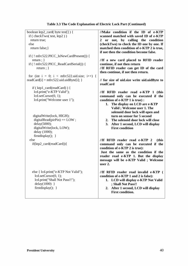
2.7. PIR Sensor (Passive Infrared Sensor)
The sensor used in this project is the passive infrared sensor (PIR). A passive infrared
sensor, as shown in Figure 2.19, is an electronic component that measures the level of
infrared light radiating from all objects in its field of view. This kind of sensor is a
pyroelectric device that detects motion by sensing changes in the infrared (radiant heat)
levels emitted by the surrounding objects. Then, when motion is detected, the PIR sensor
outputs a high signal on its output pin. Unlike the common infrared sensors which consists
of an IR LED and a phototransistor, the PIR does not emit any waves such IR LEDs.
Objects that can be detected by this sensor is usually the human body [10]. The pin
configuration and function of PIR sensor pin can be seen in Figure 2.20 and Table 2.5 [10].
Figure 2.19 PIR sensor [10]

President University 23
Table 2.5 Pin Function of PIR Sensor
Pin Name Type Function
1 GND Ground Ground
2 VCC Power Supply Voltage: 3 V to 6 V
3 OUT Output PIR signaling; HIGH = Movement
LOW = No movement
The human body emits infrared energy at a wavelength of 9 to 10 μm. So, an infrared filter that
passes wavelengths from 8 to 14 μm is placed in front of the sensor to boost sensitivity to the
infrared energy given off by people. Second, a Fresnel lens positioned in front of the sensor
performs two functions. It concentrates the IR energy emitted over a wider area onto the sensor
and it divides the area into hot and cold zones of sensitivity. As a person walks across the
zones, the sensor sees a changing IR value that produces a varying output signal from the
sensor, indicating motion. The comparator looks for and responds to this changing signal. Hot
items that do not move, like heaters and lights, do not produce output variations. The
comparator ignores these constant IR sources. The pyroelectric material in a PIR sensor
generates an electric charge proportional to the amount of thermal energy striking it. As a
person walks past the sensor, their higher body temperature boosts sensor output. The change
is amplified and sent to a comparator that detects the difference from prior readings [11]. The
block diagram of how the sensor work can be seen in Figure 2.21.
Figure 2.20 Pin configurations of PIR sensor [10]
President University 24
2.8. 12 V Relay
A relay, as shown in Figure 2.22, is an electrical switch that uses an electromagnetic force
to operate. It takes a relatively small amount of power to turn on a relay, but the relay can
control something that draws much more power. There are three types of configuration of
relay contacts, as shown in Figure 2.23, including: Normally Open (NO), Normally
Closed (NC), and Change Over (C) .
Figure 2.21 PIR sensor block diagram [11]
Figure 2.22 12V Relay
Figure 2.23 Relay pin explanation

President University 25
When the coil gets electricity by connecting the power supply (VCC and GND) to the coil
terminal, there will be an electromagnetic force that will attract the armature and the
contact will move from NC (normally close) to NO (normally open). By the time the
current is stopped, the magnetic force will be lost, the armature will return to original
position (NC contact). For common terminal, it can be connected to the ground or VCC
from any device that requires automatic switching. The parts of the relay can be seen in
Figure 2.24.
In this final project, the author used 12 V relay (Type: HRS4H-S DC12V), as shown in
Figure 2.22, in designing a backup power for the whole system. The specifications of the
relay can be seen in Table 2.6 [13].
Table 2.6 12 V Relay Specifications
Coil Nominal 12 V
Operate Voltage 9 V
Coil Resistance¦¸ +/- 10% 400
Release Voltage 1.20 V
Coil Nominal 360 mW
Figure 2.24 Parts of the relay [12]

President University 26
2.9. Solenoid Door Lock
A solenoid door lock, as shown in Figure 2.25, is a remote door locking mechanism that
will open in the presence by an electromagnetic field. A solenoid door lock pulls the latch
when a push button or other switch is activated. The latch will then be returned to its
original position until the button is pushed or the switch is activated again. This type of
door lock is used in an electric door lock system.
In the case of access doors in buildings, a latch in the lock mechanism located in the door
is pushed into a socket in the frame. This is to prevent the door from being opened. A
simple setting arrangement allows the latch to be closed and retained in the lock condition.
The specifications of the solenoid door lock can be seen in Table 2.7 [14].
Table 2.7 Specification of Solenoid Door Lock
Material Metal, Electronic Parts
Rated Voltage DC 12V
Rated Stroke & Force 2mm, 1.2Kg(Primary)
5mm, 0.75Kg(Secondary)
Power 11.52W
Current 0.96A
Total Size 6.8 x 4.2 x 3.1cm / 2.7'' x 1.65'' x
1.2''(L*W*H)
Wire Length 20cm / 7.87''
Mounting Hole Diameter 4.5mm / 0.177"
Net Weight 209g
Figure 2.25 Solenoid door lock

President University 27
2.10. Transistor TIP122
TIP122 is a type of NPN transistor. In this project, the author used a transistor as an
electronic switch to drive the solenoid door lock. Figure 2.26 shows the pins of a transistor
which are basis, emitter, and collector. If the basis pin is given high state (1) from the
microcontroller, then the current will flow from collector to emitter. The solenoid
mechanism will pull the latch (open). Vice versa, if the basis pin is given low state (0),
then there is no current flowing through the transistor and the solenoid mechanism will
release the latch (close).
2.11. Voltage Regulator LM 7812
LM 7812, which is shown in Figure 2.27, is a voltage regulator integrated circuit (IC). It is
applied to generate regulated and constant output voltage. The last- two digit of the IC
number indicates the output voltage. For example, 7812 with the last- two digits of 12
means that the output voltage from this regulator is 12 V. The input voltage for this IC
must be higher than the output voltage while the input current required always follows the
value of output current. This IC has the ability to deliver output current up to 1.5 A. LM
7805 has three pins which are input pin, ground pin, and output pin.
Figure 2.26 Pin configurations of transistor TIP122 [15]

President University 28
To make a voltage regulator works optimally, it must be put into a circuit that consists of
capacitors. Figure 2.28 shows the implementation of voltage regulator in the circuit. The
values of capacitors used are 1000 μF (35 V) and 330 μF (25 V)
The function of these capacitors is to filter all the ripple that will come from the voltage
source. This capacitor will act as a bypass capacitor. The value of the required capacitors
can be determined from the used voltage regulator. The higher the output voltage of a
voltage regulator, the higher must be the magnitude of the capacitor used in the voltage
regulator circuit.
2.12. Digital Buzzer Module
A buzzer is an electronic device that converts electrical signals into sound waves. It works
with DC voltage. The price of buzzer in the market is relatively cheap, with the variety of
specifications. The working voltage of a buzzer may vary among 5 V, 9 V, 12 V, and 24 V.
Figure 2.27 Pin configurations of LM 7812 [16]
Figure 2.28 Application circuit for LM 7812

President University 29
Buzzers are typically used for indicator system. For example, an alarm. In this project, the
author used a digital buzzer module from DFRobot as shown in Figure 2.29, with the
working voltage of 5 V.
In order to operate the digital buzzer module from DFRobot, the pin shown in Figure 2.30
must be connected to the microcontroller. There are 3 pins that must be configured
correctly to make the device works properly.
a) Pin 1 = GND. Connected to the ground of the microcontroller.
b) Pin 2 = VCC. Connected to 5 V of the microcontroller. This is the voltage that is
needed to power up the digital buzzer module.
c) Pin 3 = Input. Connected to a digital pin of the microcontroller.
Figure 2.29 Digital buzzer module from DFRobot [17]
Figure 2.30 Pin configuration of digital buzzer module [17]

President University 30
2.13. Push Button
A push button is a simple switch mechanism for controlling some aspects of the circuit on
the device. In this project, the author used a push button as shown in Figure 2.31. The
function of the push button is to unlock the door from inside the house.
In order to make the push button works properly, one digital pin from Arduino Mega needs
to be configured as the input for the push button. The input to this pin can be high (pulled
to VCC) or low (pulled to ground). In order to prevent an unknown state (floating), the
author needs to design a logic circuit. This logic circuit with pull-down resistor will ensure
that the pin is in either at high or low state. The circuit can be seen in Figure 2.32.
2.14. AC/DC Adaptor
An adaptor, as shown in Figure 2.33, is an electronic device that can change high voltage
(AC) into low voltage (DC). This adaptor converts the 220 V AC from the power line to
Figure 2.31 Push button
Figure 2.32 Application circuit for push button

President University 31
DC with the magnitude from 3 V up to 12 V. An AC/DC Adaptor is used as the voltage
source of the whole circuit in this project. There are 2 polarities in the adaptor, positive and
negative. The author set the adaptor to 12 V and negative polarity. In the reality, the output
voltage of the AC/DC Adaptor is 18 V. Later on, this voltage will be connected to the input
of a voltage regulator with the output of 12 V.
.
2.15. Accumulator
An accumulator, as shown in Figure 2.34, is a device that can store electrical energy in the
form of chemical energy. The accumulator of motorcycle is used in this project. The type
is dry accumulator with the capacity of 6 Ah and the output voltage of 12 V. In the reality,
the output voltage of the accumulator is 13 V. The accumulator will be utilized as power
backup in case AC/DC adaptor fails to do its task.
Figure 2.33 AC/DC adaptor
Figure 2.34 Accumulator

President University 32
CHAPTER 3
DESIGN IMPLEMENTATION
3.1. System Overview
The design implementation of the system in this project is categorized into two parts:
hardware implementation and software implementation. Door security system using e-KTP
reading and passive infrared sensor utilizes the Arduino Mega 2560 as the controller of the
whole system. The Arduino Mega 2560 processes the input signal from an RFID reader, a
passive infrared sensor (PIR Sensor), and a push button. It sends output signals to an LCD
16x2, a buzzer, and a solenoid door lock. The block diagram of the system can be seen in
Figure 3.1.
The RFID reader will send input signal to Arduino Mega 2560. If the ID matches with the
stored ID in the Arduino Mega 2560, the solenoid door lock will open for a while and the
LCD will display “Valid” message. Otherwise, if the ID does not match with the stored ID
in the Arduino Mega 2560, the LCD will display “Not Valid“ message and the solenoid
door lock will kept locked. After all the work of the components on the output are finished
as programmed, the system goes back to the first setup condition. The condition is: the
solenoid door lock is closed, the buzzer is off, and the LCD displays the “Welcome”
message.
Figure 3.1 Block diagram of the system

President University 33
In order to increase the security level, the author used a passive infrared sensor (PIR
sensor). The sensor is used to detect the presence of human when the door is breached or
when there are unauthorized people going through the door without using a valid e-KTP
card. When the PIR sensor detects the presence of human, it will send an input signal to the
Arduino Mega 2560. After that, the Arduino Mega 2560 will send the output signal to the
buzzer. The buzzer will sound for 18 s. The PIR sensor is activated when the system is in
the first setup condition. When the RFID reader reads the valid e-KTP or when the Push
Button 1 is pressed, the PIR sensor will be in low state (0) until the system changes to lock
condition.
Push Button 1 is used to unlock the door from inside the house. When this push button is
pressed, it will send input signal to the Arduino Mega 2560. After that, the Arduino Mega
2560 will send an output signal to the solenoid door lock to open it for 10 s, and then it will
close again. Push Button 2 is used as on/off switch for the PIR sensor. If it is pressed for
the first time, the sensor will be off. If the sensor needs to be activated again, this Push
Button 2 has to be pressed again. The buzzer is used to help indicating whether the sensor
is on or off. The buzzer will sound one short beep if the sensor is off. It will sound two
short beeps if the sensor is on.
3.2. Hardware Implementation
3.2.1. RFID reader (MFRC522) implementation
The RFID reader (MFRC522) needs serial peripheral interface (SPI compatible), so that it
can be connected to the Arduino Mega 2560. The SPI interface consists of MISO (Master
In Slave Out), MOSI (Master Out Slave In), SCK (Clock), and SS (Slave Select). The pin
configurations of the SPI are compatible to the Arduino Mega 2560. The connection of the
MFRC5222 to the Arduino Mega 2560 can be seen in Table 3.1 and Figure 3.2.

President University 34
Table 3.1 Pin Configurations of RFID Reader (MFRC522)
Device
SPI Compatible (Pin configurations)
MISO MOSI SCK SS Reset VCC Ground
Arduino Mega
2560
Digital
Pin 50
Digital
Pin 51
Digital
Pin 52
Digital
Pin 53
Digital
Pin 10
3.3 V /
VCC pin
Ground
pin
MFRC522 Pin 4 Pin 5 Pin 6 Pin 7 Pin 2 Pin 1 Pin 3
3.2.2. LCD 16x2 implementation
A liquid Cristal Display (LCD) 16x2 is used to display the running process mode of the
system. The LCD requires 3 control pins (RS, RW, E) and 8 data pins (D4 - D7). 5 more
pins are needed to power the LCD, to control the display contrast, and to apply the
backlight. The pin configurations of the LCD to the Arduino Mega 2560, as shown in
Figure 3.3, can be seen in Table 3.2:
Figure 3.2 Pin configurations of RFID reader (MFRC522)

President University 35
Table 3.2 Pin Configurations of LCD 16x3
Device
Pin configurations
RS RW E Data VDD VSS VO BLK BLA
Arduino
Mega
2560
Digital
Pin 2
Ground
pin
Digital
Pin 3
Digit-
al Pin
4-7
5 V /
VCC
pin
Ground
pin
Potenti-
ometer
10 kΩ
Grou-
nd pin
Resist-
or
220 Ω
LCD
16x2
Pin 4 Pin 5 Pin 6 Pin
11-14
Pin 2 Pin 1 Pin 3 Pin 16 Pin 15
Figure 3.3 Pin configurations of LCD 2x16

President University 36
3.2.3. PIR Sensor. digital buzzer module, and push button implementation
The pin configurations of the PIR sensor, the digital buzzer module, and the Push Button 1
can be seen in Figure 3.4. The PIR sensor has 3 pins which are connected to the Arduino
Mega 2560. Pin 1, which is the Ground pin is connected to the ground pin of Arduino. Pin
2, the output pin, is connected to the Arduino digital pin (pin 9). Pin 3, the VCC pin, is
connected to the Arduino VCC pin (5 V).
The digital buzzer module also has 3 pin. Pin 1, the Ground pin, is connected to the
Arduino ground pin. Pin 2, the VCC pin, is connected to the Arduino VCC pin (5 V). Pin
3, the input pin, is connected to Arduino digital pin (pin 8).
The push button needs to use a pull-down resistor before it is connected to the Arduino
Mega 2560. In this project, the author used the resistor of 22 kΩ (R1 and R2) to become
the pull-down resistors for push buttons. The output of the push button is connected to the
Arduino digital pin. Push Button 1 connected to the digital pin 11 and the Push Button 2 to
the digital pin 12. VCC of the push button circuit is connected to the Arduino VCC pin (5
V). All the grounds are connected to the Arduino ground pin.
Figure 3.4 Pin configurations of PIR sensor, digital buzzer module, Push Button 1,
and Push Button 2

President University 37
3.2.4. Solenoid door lock and power circuit implementation
A control circuit is implemented to control the solenoid door lock. The control circuit used
the TIP122 NPN transistor as a switch. The transistor TIP122 has 3 pins. The first pin
(base pin) is connected to resistor of 1 kΩ and then to the Arduino digital pin (pin 14). The
second pin (collector pin) is connected to the ground of the power circuit. The third pin
(emitter pin) is connected to the ground of the solenoid door lock. In order to prevent any
feedback current from the solenoid door lock, the author used the diode 1N4006. The diode
is connected to the collector pin of the transistor and then to the VCC of the power circuit.
An AC/DC adaptor is used to power all of the system in this project. Accumulator is
utilized as the power backup when the blackout occurs. In order to make an automatic
power backup, the author used a 12 V relay. The 12 V relay has 5 pins. The first pin is NO
(normally open) pin. It is connected to the VCC of the AC/DC adaptor. The second pin is
NC (normally close) pin. It is connected to the VCC of the accumulator. The third and
fourth pin are coil pins. They are connected to the VCC and the ground of the AC/DC
adaptor. The fifth pin is C (Control) pin. It is connected to the voltage regulator, the
solenoid door lock, and the diode from the collector pin of the transistor. The relay will be
in the condition of NO when there is current flowing from the AC/DC adaptor through the
coil. If a blackout occurs or there is no current flows through the coil, the relay will be in
the condition of NC. In the condition of NO, the power for the circuit is supplied by the
AC/DC adaptor. Otherwise, in the condition of NC, the power for the circuit is from the
accumulator.
The voltage regulator LM7812 is used to stabilize the voltage to 12 V to power the
Arduino Mega 2560. The author used the LM7812 because the real output voltage of the
AC/DC adaptor and the accumulator is higher than 12 V. The recommended power supply
for Arduino itself is 7-12 V. The author used capacitors before the regulator (C1) and after
regulator (C2) to filter all the ripples that come from the voltage source. The values of
capacitor 1 (C1) is 1000 μF (35 V) and for capacitor 2 (C2) is 330 μF (25 V). There is no
strict requirement for these values of capacitors. The higher the voltage that needs to be
regulated, the higher must be the magnitude of the capacitor. All of the configuration of the
power circuit and the solenoid door lock can be seen in Figure 3.5.

President University 38
3.3. Programming Implementation
3.3.1. Arduino programming
The Arduino Mega 2560 is programmed by using Arduino IDE. The Arduino programs are
written in C or C++. The programming is used to control all the inputs and the outputs of
the system in Arduino Mega 2560. The LCD 16x2 and MFRC522 need to make
communication with Arduino Mega 2560. The programming in Arduino IDE needs the use
of additional library. The Arduino IDE itself has two main functions, which are setup()
and loop().
Setup() is a function in Arduino IDE that runs only one time at the start of a program. This
can be used to initialize settings. Thus, in order to initialize the input and the output of the
components used in the system, they need to be declared in Setup() function. Loop() is a
function that runs continuously in an endless loop until the Arduino power is turned off.
Figure 3.5 Pin configurations of solenoid door lock and power circuit

President University 39
3.3.2. Main programming code
In this sub section, the main programming code that plays the important role in the system
will be explained. The code, the explanation of it, and the flow chart are separated into two
parts. The first part, as shown in Table 3.3, is electric lock part. This is to explain the code
implemented on the RFID reader (MFRC522), the solenoid door lock, the LCD, and Push
Button 1. The second part, as shown in Table 3.4, is the sensor part. This is to explain the
code implemented on the sensor, the buzzer, and Push Button 2. The flow chart of part 1
and part 2 can be seen in Figure 3.6 and Figure 3.7. In the flow chart of the electric lock,
the author created a shorthand for each of the messages that will be displayed on the LCD,
it can be seen in table 3.5. The complete code used in this project can be seen in Appendix
A.
Table 3.3 The Code Explanation of Electric Lock Part
Code Explanation
byte ktp1[7] =
0x04,0x23,0x49,0xB2,0x84,0x29,0x80;
byte ktp2[7] =
0x04,0x4D,0x48,0xA2,0x4C,0x28,0x80;
byte readCard[7];
boolean match = false;
boolean checkTwo ( byte a[], byte b[] )
if ( a[0] != NULL )
match = true;
for ( int k = 0; k < 7; k++ )
if ( a[k] != b[k] )
match = false;
if ( match )
return true;
else
return false;
boolean ktp1_card( byte test[] )
if ( checkTwo( test, ktp1 ) )
return true;
else
return false;
//Save 7 Bytes of Unique ID of e-KTP 1 and
2 on the arduino programming. Author
writes byte [7], because total amount of
Unique ID of one e-KTP is 7 bytes or 56
bits.
//Store scanned ID read from RFID reader
//Initialize the match condition to false
//Make condition to check ID of e-KTP
scanned, one by one until all ID read. The
name of this condition is checkTwo, the
function of byte a[] and byte b[] is to be
placed by saved ID and current scanned e-
KTP ID.
//Make sure if there is something in the
array first (NULL means nothing) then
continue. //Assume they match at first.
//After that, loop 7 times to check the ID
one by one. Because e-KTP has 7 bytes ID.
//IF the ID doesn’t match then set match
condition into false.
//If its match, then set the match condition
into true
// make sure if the ID does not match, then
the match condition is false
//Make condition if the ID of e-KTP
scanned matched with saved ID of e-KTP 1
or not, by calling the condition (checkTwo)
to check the ID one by one. If matched then
condition of e-KTP 1 is true, if not then the
condition become false.
President University 40
Table 3.3 The Code Explanation of Electric Lock Part (Continued)
boolean ktp2_card( byte test[] )
if ( checkTwo( test, ktp2 ) )
return true;
else
return false;
if ( ! mfrc522.PICC_IsNewCardPresent())
return ;
if ( ! mfrc522.PICC_ReadCardSerial())
return ;
for (int i = 0; i < mfrc522.uid.size; i++)
readCard[i] = mfrc522.uid.uidByte[i];
if ( ktp1_card(readCard) )
lcd.print("e-KTP Valid");
lcd.setCursor(0, 1);
lcd.print("Welcome user 1");
digitalWrite(lock, HIGH);
digitalRead(pirPin) == LOW ;
delay(5000);
digitalWrite(lock, LOW);
delay (1000);
firstdisplay();
else
if(ktp2_card(readCard))
else lcd.print("e-KTP Not Valid");
lcd.setCursor(0, 1);
lcd.print("Shall Not Pass!!");
delay(1000)
firstdisplay();
//Make condition if the ID of e-KTP
scanned matched with saved ID of e-KTP
2 or not, by calling the condition
(checkTwo) to check the ID one by one. If
matched then condition of e-KTP 2 is true,
if not then the condition become false.
//If a new card placed to RFID reader
continue, if not then return
//If RFID reader can get ID of the card
then continue, if not then return.
// for size of uid.size write uid.uidByte to
readCard
//If RFID reader read e-KTP 1 (this
command only can be executed if the
condition of e-KTP 1 is true) :
1. The display on LCD are e-KTP
Valid ; Welcome user 1. The
solenoid door lock will open and
turn on sensor for 5 second
2. The solenoid door lock will close
3. After 1 second, LCD will display
First condition
//If RFID reader read e-KTP 2 (this
command only can be executed if the
condition of e-KTP 2 is true):
Just the same as the condition if the
reader read e-KTP 1. But the display
message will be e-KTP Valid ; Welcome
user 2.
//If RFID reader read invalid e-KTP (
condition of e-KTP 1 and 2 is false):
1. LCD will display e-KTP Not Valid
; Shall Not Pass!!
2. After 1 second, LCD will display
First condition.

President University 41
Table 3.3 The Code Explanation of Electric Lock Part (Continued)
if (digitalRead (button1)==HIGH)
digitalWrite(lock, HIGH);
digitalRead(pirPin) == LOW ;
delay(10000);
digitalWrite(lock, LOW);
digitalRead(pirPin) == LOW ;
delay(5000);
else
digitalWrite(lock, LOW);
//If Push Button 1 pressed (HIGH), then
Solenoid door lock will open, and sensor
will OFF
//After 10 second solenoid door lock will
close, but sensor still OFF until 5 second
//If push button 1 is not pressed, and then
solenoid door lock will remain close.
Table 3.4 The Code Explanation of Sensor Part
Code Explanation
boolean sensorActive = true;
int reading;
int previous = LOW;
if (sensorAktif)
if (digitalRead(pirPin) == HIGH)
for(int i = 0; i <60 ; i++)
if ((digitalRead (button2)==HIGH ) &&
previous == LOW)
digitalWrite(buzzer, LOW);
break;
else
digitalWrite(buzzer, HIGH);
delay (200);
digitalWrite(buzzer, LOW);
else
digitalWrite(buzzer, LOW);
if (digitalRead(button2) == HIGH) &&
previous == LOW )
//Make the condition of sensorActive =
true. The function is to activate the sensor.
//Make variable reading to store the
current state of push button 2
//Make variable previous equal to LOW,
the function is to represent the current
reading from the push button2.
//If the condition of sensorActive is true,
then sensor will be activated and ready to
detect presence of human.
//If sensor detect the presence of human,
then buzzer will sound for 18 second
//While the buzzer sound, user can turn off
the alarm by pressing push button 2. This
command can only be executed when
button2 pressed and the condition before
pressed is LOW.
//Break; has functions to quit from “for”
loop, bypassing the normal loop condition.
//Buzzer sound for 18 second
//If the condition of sensorActive is false,
then turn off sensor
//If push button 2 pressed (HIGH) for the
first time and the current condition before
pressed is LOW then :

President University 42
Table 3.4 The Code Explanation of Sensor Part (Continued)
if (sensorActive)
sensorAktif = false;
digitalWrite(buzzer, HIGH);
delay (600);
digitalWrite(buzzer, LOW);=
else
sensorAktif = true;
for(int i = 0; i <2 ; i++)
digitalWrite(buzzer, HIGH);
delay (600);
digitalWrite(buzzer, LOW);
delay (200);
digitalRead(pirPin) == LOW ;
delay (5000);
previous = reading;
//If sensorActive condition is true then
switch it to become false to make sensor
OFF
//Buzzer will sound once as sign to indicate
sensor is OFF
//If push button 2 pressed but the previous
reading is HIGH it means buton2 pressed
for second time then condition of
sensorActive is true, it means sensor will
ON
//Buzzer will sound twice as sign to indicate
sensor is ON
//After push button pressed once, the
previous condition become High, so the
push button function as a switch.
//Make variable for previous reading =
reading in order to make the state after
fush button pressed for first time.
Table 3.5 Display message on LCD
LCD Mode Display message
First Display (-:Welcome:-) ; Waiting e-KTP
Mode 0 Calibrating PIR ; For 10s
Mode 1 e-KTP valid ;
Welcome user 1 (for e-KTP 1)
Mode 2 e-KTP valid ;
Welcome user 2 (for e-KTP 2)
Mode 3 e-KTP not Valid ; Shall Not Pass!!

President University 43
Figure 3.6 Flow chart of electric lock part

President University 44
Figure 3.7 Flow chart of sensor part

President University 45
CHAPTER 4
RESULTS AND DISCUSSION
4.1. Results
The front view of the automatic door lock system can be seen in Figure 4.1. The automatic
door consists of the door itself and the frame of the door. The size of the frame is 49.5 cm
x 44.5 cm x 8.5 cm, and for the door is 44.5 cm x 39.5 cm x 8.5 cm. The LCD and the
RFID reader are placed on the front side of the door. The back side and left view of the
automatic door can be seen in Figure 4.2. On the back side, we can find the Push Button 1
and a small door. The size of the small door is 30 cm x 19.5 cm x 2.5 cm. On the right side,
there is a solenoid door lock. It can be seen when the door is open (see Figure 4.2).
Figure 4.1 Front view of the automatic door

President University 46
The main hardware of the system is put inside the small door. In order to access the main
hardware of the system, the small door in the back of the door must be opened (see Figure
4.3). The Arduino Mega 2560 as the controller of the whole system, and also the main
circuit, the digital buzzer module, and Push Button 2 are stored there. The main circuit
consists of the power circuit and the transistor circuit. The size of Push Button 2 is very
small. The location of this push button is also covered by the cable. Because the function
of Push Button 2 is to switch off and switch on the sensor, only authorized people will
know where it is located. The top view of the automatic door, as shown in Figure 4.4,
shows the location of the PIR sensor. The PIR sensor is placed on the top of the door in
order to make it works properly and also to ease the arrangement of the sensor’s cable. The
cable must be connected to the Arduino Mega 2560. Thus, the top side of the frame is the
best place to put the PIR sensor.
(a) (b)
Figure 4.2 The automatic door
(a) Back view; (b) Left view

President University 47
When the power supply cable is plugged in, the LCD displays the message “Calibrating
PIR for 10 s”, as shown in Figure 4.5. During this 10 s, the sensor will not be able to detect
the presence of human. The PIR Sensor requires a warm up time in order to work properly.
This time also gives a chance time for the sensor to learn its environment. After 10 s, the
display message on LCD will change to “Welcome Waiting e-KTP” messages (see Figure
4.6).
Figure 4.3 Main hardware of the system
Figure 4.4 Top view of automatic door

President University 48
When the RFID reader scans e-KTP 1 or e-KTP 2, then the message display on LCD will
be changed to “e-KTP Valid” message to user 1 (e-KTP) or to user 2 (e-KTP 2), as show in
Figure 4.7. The solenoid door lock will open for 10 s. When RFID reader scans a not valid
e-KTP, then the message display on LCD is “e-KTP Not valid, Shall not Pass!!” message
(see Figure 4.8). The conditions of the solenoid door lock when latch is pulled or released
can be seen in Figure 4.9.
Figure 4.6 “Welcome Waiting e-KTP” message displays on LCD
Figure 4.7 “Valid” Message to user 1 (left) and to user 2 (right)
Figure 4.5 “Calibrating PIR for 10 s message displays on LCD

President University 49
The door can also be open for 10 s by pressing the Push Button 1. When the door is
breached, the PIR sensor will be able to detect it. The buzzer will sound for 18 s. If the user
wants to open the door for a longer time without being detected by the PIR sensor, the
Push Button 2 must be pressed first. The buzzer will sound once to indicate that the PIR
sensor is turned off. Push Button 2 must be pressed again to re-active the PIR sensor and
the buzzer will sound twice to indicate that the PIR sensor is turned on.
Figure 4.8 “e-KTP Not valid Shall not Pass!!” message displays on LCD
(a) (b)
Figure 4.9 Solenoid door lock
(a) Open State; (b) Close State

President University 50
4.2. Discussion
In this project, the strengths are:
1. The buzzer will be on with annoying sound if door is breached.
2. The sensor can be switch on or switch off manually by pressing Push Button 2.
3. The door lock system has its own power backup which is useful when a blackout
occurs.
The weakness is:
1. The unique ID of e-KTP must be saved manually on the Arduino program. This
takes time. In order to add more e-KTPs as the key, the author has to scan the
unique ID of the new e-KTPs and then save them in Arduino program.

President University 51
CHAPTER 5
CONCLUSSION
5.1. Conclusions
Based on the results of the project, “Door Security System Using e-KTP Reading and
Passive Infrared Sensor”, there are two conclusions that can be taken. They are:
1. The project was successful in implementing an RFID technology to an automatic
door lock system and in designing an RFID system that uses e-KTP as the key for
an electric door lock. The door can be unlocked from the outside by using e-KTP,
and will be lock automatically after 10 s. The unique data from the e-KTP must be
stored first in Arduino program. Only such e-KTP can be used as the key to unlock
the door.
2. The PIR sensor was successfully implemented on the door. It will be active when
someone goes through the door without using valid e-KTP or pressing the Push
Button 1. The sensor can be manually turn on or turn off by pressing Push Button 2
In conclusion, the device works well and the objectives of this final project are achieved.
5.2. Recommendations
There are several possibilities to develop and improve the result of this final project. Two
recommendations that can be given are:
1. Applying a closer to the automatic door
A closer, as shown in Figure 5.1, is a device that can close the door automatically after
the door is opened. The duration for the closer to make the door closed is adjustable.
When Push Button 1 is pressed or the RFID reader scanned valid e-KTP, the PIR
sensor must be inactivated for a while. By using the closer, the delay time of PIR
sensor can be exactly known.

President University 52
2. Applying an automatic accumulator charger
An automatic accumulator charger, as shown in Figure 5.2, is the charger for
accumulator that will stop charging automatically when the accumulator is fully
charged. Accumulator is used in this project to back up the power when a blackout
occurs. By applying an automatic accumulator charger in this project, the accumulator
will be charge automatically when the electricity is back again.
Figure 5.1 Door closer
Figure 5.2 Automatic accumulator charger

President University 53
REFERENCES
[1] Robot shop. Arduino Mega 2560 Datasheet.
[2] Arduino reference, Retrieved January 2015 from
http://arduino.cc/en/Reference/SPI
[3] Monk, Simon. (2012) “Programming Arduino: Getting Started With Sketches”.
United States: The McGraw-Hill Companies.
[4] Finkenzeller, Klaus. (2010) “RFID Handbook: fundamentals and applications in
contactless smart cards, radio frequency identification and near-field
communication”. 3rd edn. Translated by Dorte Muller. West Sussex: John Wiley &
Sons Ltd.
[5] Dobkin, Daniel. (2008) “The RF in RFID: Passive UHF RFID in Practice”. Oxford:
Elsevier Inc.
[6] Jechlitschek, Christoph. (2006, April 24) “Survey Paper on Radio Frequency
IDentification (RFID) Trends”.
[7] NXP Semiconductors. MFRC522 Datasheet.
[8] Nugroho, Anto Satriyo. (2013, May 10) Membedah teknologi e-KTP. Wordpress,
[Blog]. Available at: https://asnugroho.wordpress.com/2013/05/10/membedah-
teknologi-e-ktp/ [Accessed January 2015]
[9] Specification for LCD module, Shenzhen Eone Electronics Co., Ltd, Shenzhen, 2005
[10] Parallax. PIR Sensor Datasheet.
[11] Repas, Robert. (2008, July 10) “Sensor Sense: Passive Infrared-Motion Sensors”.
[Online]. Available at: http://machinedesign.com/news/sensor-sense-passive-
infrared-motion-sensors [Accessed January 2015]
[12] Kilian, Christopher T. (2001) “Modern Control Technology: Components and
Systems”. Michigan: Delmar Thomson Learning
[13] HKE Relays. (2006) hrs4h-s-dc12v relay Datasheet.
[14] Solenoid door lock specification. Retrieved January 2015 from
http://www.sourcingmap.com/12v-096a-2mm-12kg-open-frame-type-solenoidfor-
electric-door-lock-p-217979.html
[15] Fairchild Semiconductor. (2008, October) TIP122 Transistor Datasheet.
[16] Jameco Electronics. (2006) LM7812 Voltage regulator Datasheet.

President University 54
[17] Digital Buzzer Module DFRobot Picture and specification. Retrieved January 2015
from
http://www.dfrobot.com/wiki/index.php/Digital_Buzzer_Module_(SKU:_DFR0032)

President University 55
APPENDIX A
SOURCE CODE
#include <SPI.h> //Library for SPI
#include <MFRC522.h> //Library for MFRC522 (RFID Reader)
#define SS_PIN 53 // slave select pin for MFRC522
#define RST_PIN 10 // reset pin for MFRC522
MFRC522 mfrc522(SS_PIN, RST_PIN);
#include <LiquidCrystal.h> //Library for LCD 16 x 2
const int PIN_RS = 2;
const int PIN_E = 3;
const int PIN_DB4 = 4;
const int PIN_DB5 = 5;
const int PIN_DB6 = 6;
const int PIN_DB7 = 7;
LiquidCrystal lcd(PIN_RS,PIN_E, PIN_DB4, PIN_DB5, PIN_DB6, PIN_DB7);
byte ktp1[7] = 0x04,0x23,0x49,0xB2,0x84,0x29,0x80;
byte ktp2[7] = 0x04,0x48,0x15,0x7A,0xC6,0x28,0x80;
byte readCard[7];
boolean match = false;
boolean sensorActive = true;

President University 56
int button2 = 12; // declare what digital pin used by input or output
int buzzer = 8;
int pirPin = 9;
int lock = 14;
int button1 = 11;
int reading; // the current reading from the input pin
int previous = LOW;
int sensor = HIGH;
void setup()
pinMode(button2, INPUT); //declare the input and output
pinMode(buzzer, OUTPUT);
pinMode(pirPin, INPUT);
pinMode(lock, OUTPUT);
SPI.begin(); // Init SPI bus
mfrc522.PCD_Init(); // Init MFRC522 card
digitalWrite(pirPin, LOW);
digitalWrite(lock, LOW);
lcd.begin(16, 2);
lcd.print("Calibrating PIR");// Calibrate sensor for 10 s
lcd.setCursor(0, 1);
lcd.print("For 10s");
delay(10000);
firstdisplay();

President University 57
digitalWrite(lock, LOW);
void loop()
if (sensorActive)
if (digitalRead(pirPin) == HIGH)
for(int i = 0; i <60 ; i++)
if ((digitalRead (button2)==HIGH ) && previous == 0)
digitalWrite(buzzer, LOW);
break;
else
digitalWrite(buzzer, HIGH);
delay (200);
digitalWrite(buzzer, LOW);
delay (100);
else
digitalWrite(buzzer, LOW);
if ((digitalRead (button2)==HIGH )&& previous == LOW )

President University 58
if (sensorActive)
sensorActive = false;
digitalWrite(buzzer, HIGH);
delay (600);
digitalWrite(buzzer, LOW);
else
for (int i = 0; i<2 ; i++)
digitalWrite(buzzer, HIGH);
delay (600);
digitalWrite(buzzer, LOW);
delay (200);
digitalRead(pirPin) == LOW ;
delay (5000);
sensorActive = true;
previous = reading;
if (digitalRead (button1)==HIGH)
digitalWrite(lock, HIGH);
digitalRead(pirPin) == LOW ;
digitalWrite(buzzer, LOW);
delay(10000);
digitalWrite(lock, LOW);
digitalRead(pirPin) == LOW ;

President University 59
delay(5000);
else
digitalWrite(lock, LOW);
if ( ! mfrc522.PICC_IsNewCardPresent()) //If a new PICC placed to RFID reader continue
return ;
if ( ! mfrc522.PICC_ReadCardSerial()) //Since a PICC placed get Serial and continue
return ;
for (int i = 0; i < mfrc522.uid.size; i++) // for size of uid.size write uid.uidByte to readCard
readCard[i] = mfrc522.uid.uidByte[i];
mfrc522.PICC_HaltA();
if ( ktp1_card(readCard) )
lcd.clear();
lcd.print("e-KTP Valid");
lcd.setCursor(0, 1);
lcd.print("Welcome User 1");
delay(500);
digitalWrite(buzzer, LOW);
digitalWrite(lock, HIGH);

President University 60
digitalRead(pirPin) == LOW ;
delay(5000);
digitalWrite(lock, LOW);
delay (1000);
firstdisplay();
else
if(ktp2_card(readCard))
lcd.clear();
lcd.print("e-KTP Valid");
lcd.setCursor(0, 1);
lcd.print("Welcome User 2");
delay(500);
digitalWrite(buzzer, LOW);
digitalWrite(lock, HIGH);
digitalRead(pirPin) == LOW ;
delay(5000);
digitalWrite(lock, LOW);
delay (1000);
firstdisplay();
else
lcd.clear();
lcd.print("e-KTP Not Valid");
lcd.setCursor(0, 1);
lcd.print("Shall Not Pass!!");
delay (1000);

President University 61
firstdisplay();
mfrc522.PICC_HaltA(); // Stop reading
return ;
boolean ktp1_card( byte test[] )
if ( checkTwo( test, ktp1 ) )
return true;
else
return false;
boolean ktp2_card( byte test[] )
if ( checkTwo( test, ktp2 ) )
return true;
else
return false;
boolean checkTwo ( byte a[], byte b[] )
if ( a[0] != NULL )
match = true;
for ( int k = 0; k < 7; k++ )
if ( a[k] != b[k] )
match = false;
if ( match ) // Check to see if if match is still true

President University 62
return true; // Return true
else
return false; // Return false
void firstdisplay()
lcd.clear();
lcd.print("(-: Welcome :-)");
lcd.setCursor(0, 1);
lcd.print("Waiting e-KTP");


