
1 | Fuel Cell Technologies Program eere.energy.gov
U.S. Department of Energy Fuel Cell Technologies Program
U.S. Department of Energy Polymer Electrolyte Membrane Fuel Cell Catalyst Development Activities
DOE’s fuel cell catalyst R&D activities Nancy L. Garland
Department of Energy Kick-off Catalyst Working Group Arlington, VA May 14, 2012

2 | Fuel Cell Technologies Program eere.energy.gov
Tech
nolo
gy
Bar
riers
*
Econ
omic
&
Inst
itutio
nal
Bar
riers
Fuel Cell Cost & Durability Targets*:
Stationary (1–10 kWe Residential CHP + DG with NG): $1,000-$1,700/kW depending on scale, 60,000-hr durability by 2020
Vehicles: $30/kW, 5,000-hr durability
Safety, Codes & Standards Development
Domestic Manufacturing & Supplier Base
Public Awareness & Acceptance
Hydrogen Supply & Delivery Infrastructure
Hydrogen Threshold Cost $2 – 4 /gge, (dispensed and untaxed)
Key Challenges
Technology Validation:
Technologies must be demonstrated under real-world
conditions. Assisting the growth of early
markets will help to overcome many
barriers, including achieving
significant cost reductions through
economies of scale.
Market Transformation
* Targets and metrics are being updated
Hydrogen Storage Capacity Target: > 300-mile range for vehicles—without compromising interior space or performance
DOE’s Hydrogen & Fuel Cells Program addresses the key challenges facing the widespread commercialization of fuel cells.
Source: US DOE 10/2011

3 | Fuel Cell Technologies Program eere.energy.gov
• Catalyst is highest stack cost at high production volumes.
Catalysts dominate FC issues
• Learning Demonstration project indicates durability needs to be increased.
• Catalyst degradation is a key aspect of performance loss.
DOE is investigating • Cost reduction by decreasing Pt
loading: – Extended Pt surfaces – Platinum alloy catalysts, including
core-shell concepts – Non-PGM catalysts – Hybrid catalysts
• Durability improvement by: – More stable structured alloys – Addition of catalyst functionality to
reduce the severity of conditions at the electrodes during start-up/shut-down cycles
– More stable catalyst supports
500,000 systems/year (2010)

4 | Fuel Cell Technologies Program eere.energy.gov
Approach Extended Surfaces
Core-shell particles
Dealloyed Particles
Non-PGM Catalysts
Activity + + + Needs improvement
Durability + ?? ?? Needs improvement
Mass transport - + + ? Other Activities in
MEAs not as high as those in RDE experiments
Activities in MEAs not as high as those in RDE experiments
Evaluation of catalyst approaches
5 | Fuel Cell Technologies Program eere.energy.gov
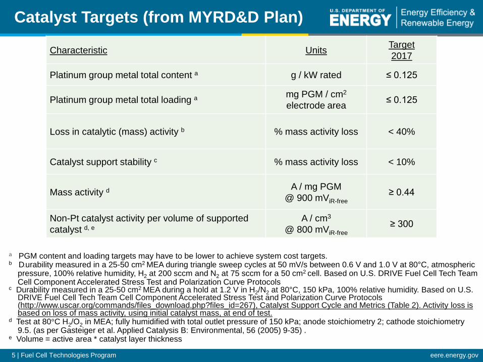
Characteristic Units Target 2017
Platinum group metal total content a g / kW rated ≤ 0.125
Platinum group metal total loading a mg PGM / cm2 electrode area ≤ 0.125
Loss in catalytic (mass) activity b % mass activity loss < 40%
Catalyst support stability c % mass activity loss < 10%
Mass activity d A / mg PGM @ 900 mViR-free ≥ 0.44
Non-Pt catalyst activity per volume of supported catalyst d, e
A / cm3
@ 800 mViR-free ≥ 300
Catalyst Targets (from MYRD&D Plan)
a PGM content and loading targets may have to be lower to achieve system cost targets. b DDurability measured in a 25-50 cm2 MEA during triangle sweep cycles at 50 mV/s between 0.6 V and 1.0 V at 80°C, atmospheric
pressure, 100% relative humidity, H2 at 200 sccm and N2 at 75 sccm for a 50 cm2 cell. Based on U.S. DRIVE Fuel Cell Tech Team Cell Component Accelerated Stress Test and Polarization Curve Protocols
c Durability measured in a 25-50 cm2 MEA during a hold at 1.2 V in H2/N2 at 80°C, 150 kPa, 100% relative humidity. Based on U.S. DRIVE Fuel Cell Tech Team Cell Component Accelerated Stress Test and Polarization Curve Protocols (http://www.uscar.org/commands/files_download.php?files_id=267), Catalyst Support Cycle and Metrics (Table 2). Activity loss is based on loss of mass activity, using initial catalyst mass, at end of test.
d Test at 80°C H2/O2 in MEA; fully humidified with total outlet pressure of 150 kPa; anode stoichiometry 2; cathode stoichiometry 9.5. (as per Gasteiger et al. Applied Catalysis B: Environmental, 56 (2005) 9-35) .
e Volume = active area * catalyst layer thickness

6 | Fuel Cell Technologies Program eere.energy.gov
Task Approach Activities
Catalysts/ Electrodes
• Develop electrocatalysts with reduced precious metal loading, increased activity, improved durability /
3M: Advanced Cathode Catalysts and Electrodes
stability, and increased tolerance to air, fuel, and system-derived impurities
3M: Durable Catalysts for Fuel Cell Protection During Transient Conditions
• Develop supports with reduced corrosion, lower cost, and increased non-PGM catalyst loading
ANL: Polymer Electrolyte Fuel Cell Lifetime Limitations: The Role of Electrocatalyst Degradation
• Optimize electrode design and assembly Argonne National Laboratory: Nanosegregated Cathode Catalysts with Ultra-Low Platinum Loading
• Develop anodes for fuel cells operating on non-hydrogen fuels
BNL: Contiguous Platinum Monolayer Oxygen Reduction Electrocatalysts on High-Stability Low-Cost Supports
GM: High-Activity Dealloyed Catalysts
lIT: Synthesis and Characterization of Mixed-Conducting Corrosion Resistant Oxide Supports
Los Alamos National Laboratory: The Science and Engineering of Durable Ultralow PGM Catalysts
Los Alamos National Laboratory: Engineered Nano-scale Ceramic Supports for PEM Fuel Cells
Northeastern University: Development of Novel Non-Pt Group Metal Electrocatalysts for PEMFC Applications
NREL: Extended, Continuous Pt Nanostructures in Thick, Dispersed Electrodes
NREL: WO3 and HPA Based System for Ultra-High Activity and Stability of Pt Catalysts in PEMFC Cathodes
University of South Carolina: Development of Ultra-Low Platinum Alloy Cathode Catalyst for PEM Fuel Cells
Current Fuel Cell Activities (from MYRD&D Plan)
7 | Fuel Cell Technologies Program eere.energy.gov 7 7
Thank you
http://www.eere.energy.gov/hydrogenandfuelcells

8 | Fuel Cell Technologies Program eere.energy.gov
Extended Surface Catalysts : Nanostructured thin film (NSTF) catalysts
0.00 0.03 0.06 0.09 0.12 0.15 0.18 0.210.0
0.1
0.2
0.3
0.4
0.5
0.6
0.7
0.8
0.9Pt3Ni7(A) after surface
energy treatment(open - XRFsolid - ICP)
Pt3Ni7(B) as-madePt3Ni7(A) as-made
PtCo(B)
3
2 Pt68(CoMn)324 3 4
13
1714
Nominally Standard NSTF whiskersMultiple MEA's, Test Stations, LotsNumber of samples = N
10 629
29
Comparison PtNi and PtCoMn Activities-graph 15, data 6
Mas
s Ac
tivity
(A/m
g Pt)
(105
0 se
c)
Pt Loading in PtM or PtCoMn (mg/cm2)
1
DOE 2015 Target
0 1 2 3 4 5 6 7 8 9 10 110.0
0.1
0.2
0.3
0.4
0.5
0.6
0.7
0.8
0.9
1.0
7.5 psig, 2/2.5 stoich, 67%RH, 80oC NSTF PtCoMn 0.05/0.10 mgPt/cm2 PEM: 3M 20 micron; GDL: 3M Std.
GM Short Stack NSTF A/C: 0.05/0.10 mg/cm2
13 µm PEM
GM Test of 3M MEAs:50cm2, two cells, 3M Protocol
3M Test of 3M MEAs:50cm2, two cells,
3M Protocol
Specifc Power Density Projections- graph 18
Cell V
olta
ge (V
)
Power / Total Loading (kW/gPt )
0.125 gPt/kWrated
0.2 gPt/kWat 650 mV
3M has developed NSTF Pt and Pt alloy catalysts on crystalline organic supports: Eliminates carbon corrosion issues, demonstrates higher
resistance to Pt dissolution, and reduces rates of degradation of the membrane by chemical attack
ORR mass activities > 0.43 A/mgPGM for surface-energy-treated Pt3Ni7 alloy catalyst
Ultra-thin catalyst layer enables higher J(A/cm2) below 0.2 mg/cm2 Requires different water management under cool/wet conditions High volume roll-to-roll production scale-able with standard
technology
805 Nanostructured Thin Film Electrocatalysts - Current Status and Future Potential, T 9:00
3M

9 | Fuel Cell Technologies Program eere.energy.gov
Synthesized novel, extended-Pt catalysts and incorporated them into thick, dispersed electrodes for improved mass transport/water management Deposited Pt on multiple substrates: carbon nanotubes, TiO2-coated Si nanowires, Cu nanowires, Ag nanowires and nanoplates NREL has demonstrated: •Pt deposited on Ag nanowires by spontaneous galvanic displacement (SGD) displays activity as high as 1,300 µA/cm2 Pt.
•Improved stability for SGD-deposited Pt nanowire catalysts compared to Pt/C.
NREL is developing extended thin film structures
2005 Stack Status
440280110
im0.9V [mA/mgPt]
2005 Cell Status
DOE2015 Target
5nm
2015 Target
808 Electrochemically Available Surface Area and Mass and Specific Activities of Extended Surface Pt Nanostructures T 10:00

10 | Fuel Cell Technologies Program eere.energy.gov
Improving Pt monolayer electrocatalysts for the ORR BNL Core-shell particles
Pt-ML on bimetallic core
STEM image
EELS intensities for Pt, Ir, and Ni before (middle) and after 50K cycles (lower panel)
PGM MA: 0.76 A/mg
SA: 0.80 mA/cm2 PGM MA: 0.57 A/mg
Pt-ML on hollow Pd core
Lowering noble metal content, increasing activity and stability by smooth surface morphology, mass-saving geometry and composition, induced lattice contraction in cores
0
100
200
300
400
0 50000 100000 150000 200000 250000
Pt/Pd9Au/C (0.105 mg
Pt cm-2)
Pt/Pd9Au/C (0.101 mg
Pt cm-2)
Pt(H)/Pd/C (0.099 mgPt
cm-2)
30% Pt/C (0.102 mgPt
cm-2)
mas
s ac
tivity
/ A
mg
Pt-1
at 0
.9V
number of potential cycles
Pt shell protected by the core; No dissolution of Pt ML; Loss of Pd
induces contraction of Pt ML thus increasing stability and activity
2ML Ir around Ni
Complete stability of improved Pt ML/Pd/C in 200,000 cycles 0.6-1.0 V at Toyota Motor Company
1057 Bimetallic Core-Protected Platinum Monolayer Shell Electrocatalysts for Fuel-Cell Cathode W 16:40

11 | Fuel Cell Technologies Program eere.energy.gov
Pt-ML on Pd wires electrodeposited on C
Electrodeposited Pd NWs on carbon NPs. FFT indicates (111) facets
Pt MA: 1.74 A/mg Pt SA: 0.76 mA/cm2 PGM MA: 0.39 A/mg
0.0 0.2 0.4 0.6 0.8 1.0 1.2 1.4 1.6-0.1
0.0
0.1
0.2
0.3
0.4
0.5
0.6
0.7
0.8
0.9
1.0
0.0
0.2
0.4
0.6
0.8
1.0
H2/O2
After 10000 cycles; 80 oC, 0.1 mg/cm2 Pt + Pd, 0.04 mgPt/cm2
Powe
r Den
sity
, W/c
m2
E, V
j, A/cm2
MEA 5 cm2 Cathode total metal loading 0.1 mg/cm2
on Toray paper PGM MA: 1.2 A/mg at 0.85 V
Improving Pt Monolayer Electrocatalysts for the ORR
1058 Pt Monolayer on Electrodeposited Pd Nanostructures-Advanced Cathode Catalysts for PEM Fuel Cells W 17:00

12 | Fuel Cell Technologies Program eere.energy.gov
Pt Co Pt Fe Co
Pt Co Ni Pt Fe Ni
Colloidal solvo - thermal approach for monodispersed PtM and PtMN NPs with controlled size and composition
Efficient surfactant removal
2. Surface chemistry PtxM(1-x) N
Dissolution of 3d elements leads to Pt-skeleton
1. Particle size effect
Optimal particle size ~ 6 nm
3. Composition effect Pt
Optimal composition of Pt-ternary NPs is Pt3MN
Co Ni Pt3NiCo
4. ORR activity
Pt< Pt3FeCo < Pt3FeNi < Pt3Co < Pt3CoNi
Impr
ovem
ent f
acto
r vs.
Pt
1
2
3
4
5
Mas
s ac
tivity
A/m
g Pt
1.0
0.5
1.5
2.0
Pt/C Pt3FeCo/C Pt3CoNi/C Pt3FeNi/C
Nanosegregated catalysts: binary and ternary systems:
~ 200°C Pt3M1N2 (NM = Fe, Co, and/or Ni)
Oleylamine oleic acid
~ 150°C
Pt-bimetallic NPs (IF~2.5) vs. Pt/C
Pt-ternary (IF~5) vs. Pt/C
1005 Rational Design and Synthesis of Pt-Bimetallic Electrocatalysts, W 8:40

13 | Fuel Cell Technologies Program eere.energy.gov
General Motors is developing dealloyed catalysts [PtM3 → ~Pt2M, M= Cu,Co,Ni,Fe,V] to increase ORR activity above that of Pt or standard Pt-alloy particles •Dealloyed PtCu3 catalysts have greater initial ORR activity (0.69 A/mgPt) than dealloyed PtCo3 (0.37 A/mgPt), but dealloyed PtCo3 shows better stability against voltage cycling
•Detailed characterization (electron microscopy and x-ray absorption spectroscopy) are providing insights towards combining the attributes of activity and durability in a single catalyst. The roles of different particle morphologies are being investigated
•Dealloying conditions are being modified to improve manufacturability and to mitigate negative effects of excess alloying-element ions, which leach to the membrane
De-alloyed Nanoparticles
HAADF STEM images of (left) single-alloy-core particle in D-PtCu3 and (right) multiple-alloy-core particle in D-PtCo3. Both show Pt-only shells.
GM 50 cm2 fuel cells; cycling 0.6-1.0 V, 50 mV/s
1110 X-ray Absorption Spectroscopy Investigation on Activity and Durability of De-Alloyed Pt3Co Cathodic Catalysts. Th 12:00

14 | Fuel Cell Technologies Program eere.energy.gov
Synthesis of Pt/PPY nanowires using multi-potential steps and Pt sputter deposition
Ceria/Carbon Bead SA ~ 60 - 75 m2/g
Mill
Ce/C Powder SA ~ 70 - 90 m2/g
Pt-Ce/C Powder ~ 4 - 9 wt% Pt
Pt
•DFT modeling show that smaller Pt nanotubes are stable only for larger coverage and symmetric structures
•(6,6) Pt nanotube binds O more strongly than Pt(111)
•(13,13) Pt nanotube binds O similar or slightly more weakly than Pt(111)
Synthesis of 2-nm ceria supports on carbon
PPY nanowires Pt-coated PPY nanowires
PPY electrodeposition
Theoretical Modeling of Novel Pt Nanoparticles
LANL - Durable Ultralow PGM Catalysts
1213 Ultra-Low Pt Load Catalysts Based on Electrochemically Synthesized Polypyrrole Nanowires F 14:00
1/4
1/2

15 | Fuel Cell Technologies Program eere.energy.gov
NE - Non-PGM Catalysts
Non-PGM ORR catalyst based on melamine precursors prepared at MSU showed good activity and durability under catalyst durability protocol, however poor durability under C-corrosion conditions
• GDEs were prepared for melamine-based catalyst using NTCNA’s spray system.
• MEAs were prepared with NRE211 as the electrolyte and JMFC GDE anodes.
RDE data
Fuel Cell data –Nissan Tech. Center
Catalyst durability test protocol Carbon corrosion test protocol
Mechanistic Studies
1069 Reasons for Kinetic Facility of Oxygen Reduction and Development of Non-Precious Cathode Catalysts for Alkaline Membrane Fuel Cell W 16:40

16 | Fuel Cell Technologies Program eere.energy.gov
0 200 400 600 800 1000 1200 14000.0
0.1
0.2
0.3
0.4
0.5
0.6
0.7
0.8 05/04/2011, Initial FePyP Cathode 07/13/2011, Best FePyP Cathode 07/22/2011, CoPyP Cathode 09/26/2011, Best CoPyP cathode
@ 1
220
mA/
cm2
@ 9
20 m
A/cm
2
Volta
ge /
V
Current Density / mA/cm2
LBNL - 3D Non-PGM Catalyst
Schematic of oxygen, proton, electron, and water transport in the thin redox polymer and the catalyst layer.
Current collector
Electrolyte phase + gas pores
CatalystCatalyst support
High activity and turnover within the catalyst layer
Decent initial (>20 hr) stability
Changing inks, metal center, loading and mediator leads to better performance
Molecular catalysts dispersed in ionomer film over carbon particles
1154 Electroreduction of Molecular Oxygen by Water-Soluble Metal Porphyrins in Trifluoromethane Sulfonic Acid Solution, Th 16:40

17 | Fuel Cell Technologies Program eere.energy.gov
The University of South Carolina, in collaboration with Yonsei University (S. Korea) is developing two types of ultra-low loading Pt catalysts: (i) Hybrid cathode catalyst (HCC)
combines a non-PGM carbon composite catalyst (CCC) as a support for a PGM-based catalyst to obtain ultra-low Pt loading.
(ii) Pt and Pt-M alloy catalysts are deposited on activated graphitic carbon support, Pt-M/AGC.
The Pt-Co HCC catalyst and Pt-M/AGC catalyst had mass activities in the range of 0.38 to 0.44 A/mgPGM at loadings of 0.1 mgPGM/cm2 approaching the DOE target.
USC - Hybrid Catalysts
After 30,000 cycles
Mass activity at 0.9 V ECSA in MEA
DOE target ≤ 40% loss ≤ 40% loss
Pt3M/AGC 34% loss
(from 0.41 to 0.27 A/ mgPt)
30% loss (from 29.5 to
20.8 m2/g)
Durability of Mass Activity of Pt3M Catalyst
0.1 10.84
0.86
0.88
0.90
0.92
0.94
0.96
0.380.154
iR-c
orre
cted
cell p
oten
tial (
V)
Mass activity (A mgPt-1)
Pt-Co/CCS Pt2Ni Commercial Pt/C
0.454
1008 Development of Ultra-Low Pt Alloy Cathode Catalyst for PEM Fuel Cells, W 10:00

18 | Fuel Cell Technologies Program eere.energy.gov
0.0
20.0
40.0
60.0
80.0
100.0
120.0
140.0
0 2000 4000 6000 8000 10000
Pulse #
ECSA
Nor
mal
ized
to B
OL
( ∆%
) FC18446, 10 ug
FC 18448, 10 ug
FC 18496, 10 ug
FC 18504, 10 ug
FC17939, 2 ug
FC18245, 2ug
Pt surface area loss rate: ~ 2% per 1,000 cycles
3M
Samples with 2 and 10 μg/cm2 of protective catalyst endured 10,000 cycles to 1.4 V OER catalyst decay rate: ~30%.
Absence of hydrogen and simultaneous presence of oxygen in separate regions of the anode results in cathode potential > 1.23 V during transients and startup/shutdown.
3M approach: modify both anode and cathode catalysts to enable PEM fuel cell systems to weather the conditions in the fuel cell at voltages beyond the thermodynamic stability of water during the transient periods.
To achieve this goal 3M will develop two major concepts:
1. Cathode catalysts with high oxygen evolution reaction (OER) activity
2. Anode catalysts with low oxygen reduction (ORR) reaction activity
3M – Protect catalysts during transient conditions
1106 Catalyst Durability for Fuel Cells under Start-up/Shut-down conditions Th 10:40

19 | Fuel Cell Technologies Program eere.energy.gov
• 3M Company R. Atanasoski, M. Debe • Argonne National Laboratory N. Markovic • Brookhaven National Laboratory R. Adzic • General Motors F. Wagner • Lawrence Berkeley National Laboratory J. Kerr • Los Alamos National Laboratory F. Garzon • National Renewable Energy Laboratory B. Pivovar • Northeastern University S. Mukerjee • University of South Carolina B. Popov
Acknowledgements

20 | Fuel Cell Technologies Program eere.energy.gov
NREL team is investigating heteropolyacids and tungsten oxide catalyst supports to increase stability and activity of Pt catalysts. •Expected to increase stability due to their higher corrosion resistance and the strong catalyst -support interaction.
•Initial tests indicate the Pt/WOX catalysts are more corrosion resistant than Pt/C, with corrosion not occurring until above 1.6V
Carbon catalyst support degradation affects durability

21 | Fuel Cell Technologies Program eere.energy.gov 9
Colloidal solvo - thermal approach for monodispersed PtM NPs with controlled size and composition
Efficient surfactant removal
Temperature induced segregation Agglomeration prevented
Optimized annealing temperature 400-500o
C
(b)
Surface chemistry
PtxM(1-x) NPs
Dissolution of 3d elements leads to Pt-skeleton
Co KαPt Lα
Pt Co
ANL Nanosegregated Catalysts for ORR
0
100
200
300
400
Impr
ovem
ent F
acto
r(v
s. P
t/C)
Mas
s A
ctiv
ity ( A
/g) before
after
0
2
4
6
Pt/C acid leachedPtNi/C
acid leached/annealePtNi/C
c
0.1M HClO4 60o
C @ 0.95V, 20mV/s
x6 Activity


