
Dave Sinclair - System Engineer
Cisco Systems
DOCSIS® What’s Next – An Overview
DOCSIS® Today and Beyond …
Presented to the SCTE San Diego Chapter

DOCSIS Today Review
DOCSIS 3.1 Drivers – The need for more speed
DOCSIS 3.1 High Level Overview
DOCSIS 3.1 Channel Anatomy
DOCSIS 3.1 Spectrum Options and Deployment Examples
Agenda

Do you remember when….
Click on image to view YouTube Video

DOCSIS Background
• DOCSIS 1.0 gave us standards-based interoperability, which means “certified” cable modems from multiple vendors work with “qualified” cable modem termination systems (CMTSs) from multiple vendors.
• DOCSIS 1.1 added a number of features, including quality of service (QoS), more robust scheduling, packet classification and other enhancements that facilitate voice services.
Data-Over-Cable Service Interface Specifications
DOCSIS
upstream
DOCSIS downstream
88 MHz 860 MHz 1002 MHz 42 MHz 5 MHz
One 6 MHz bandwidth
downstream channel,
64- or 256-QAM
One upstream channel,
typically 1.6 MHz or 3.2
MHz bandwidth

DOCSIS Background
• DOCSIS 1.x supported several upstream data rates, ranging from a low of 320
kbps to a high of 10.24 Mbps. It also supported two modulation formats –
quadrature phase shift keying (QPSK) and 16-QAM – as well as five upstream RF
channel bandwidths.
• DOCSIS 1.1 added some enhancement to upstream transmission robustness,
using 8-tap adaptive pre-equalization.
Channel bandwidth, MHz
Symbol rate, ksym/sec
QPSK raw data rate, Mbps
QPSK nominal data rate, Mbps
16-QAM raw data rate, Mbps
16-QAM nominal data rate, Mbps
0.200 160 0.32 ~0.3 0.64 ~0.6
0.400 320 0.64 ~0.6 1.28 ~1.2
0.800 640 1.28 ~1.2 2.56 ~2.4
1.60 1,280 2.56 ~2.3 5.12 ~4.8
3.20 2,560 5.12 ~4.6 10.24 ~9.0

DOCSIS Background
• DOCSIS 2.0: Higher upstream data throughput per RF channel, up to 30.72 Mbps
• DOCSIS 2.0 supported 64-QAM in the upstream – plus 8-QAM and 32-QAM – and optionally supported 128-QAM trellis coded modulation (TCM) encoded modulations for S-CDMA channels – and up to 6.4 MHz channel bandwidth.
• To facilitate more robust upstream data transmission, DOCSIS 2.0 introduced advanced PHY (24-tap pre-equalizer, improved FEC, ingress cancellation, direct sampled RF in burst receiver, etc.)
DOCSIS
upstream
DOCSIS downstream
88 MHz 860 MHz 1002 MHz 42 MHz 5 MHz
One 6 MHz bandwidth
downstream channel, 64-
or 256-QAM
One upstream channel, up to
6.4 MHz bandwidth
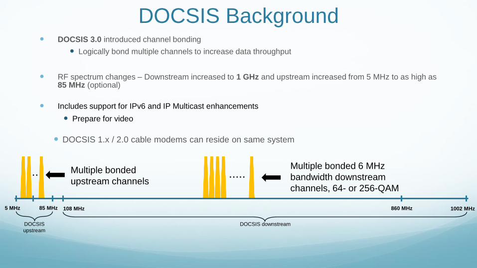
DOCSIS Background DOCSIS 3.0 introduced channel bonding
Logically bond multiple channels to increase data throughput
RF spectrum changes – Downstream increased to 1 GHz and upstream increased from 5 MHz to as high as 85 MHz (optional)
Includes support for IPv6 and IP Multicast enhancements
Prepare for video
DOCSIS 1.x / 2.0 cable modems can reside on same system
DOCSIS
upstream
DOCSIS downstream
85 MHz 860 MHz 1002 MHz 5 MHz
Multiple bonded 6 MHz
bandwidth downstream
channels, 64- or 256-QAM
Multiple bonded
upstream channels .....
108 MHz
..

DOCSIS Today Review
DOCSIS 3.1 Drivers – The need for more speed
DOCSIS 3.1 High Level Overview
DOCSIS 3.1 Channel Anatomy
DOCSIS 3.1 Spectrum Options and Deployment Examples
Agenda

Why DOCSIS 3.1? Why not just continue with DOCSIS 3.0?
DOCSIS 3.0 could scale to gigabit-class speeds
DOCSIS 3.1 will scale better, and is more spectrally
efficient than today’s single carrier quadrature amplitude
modulation (SC-QAM) technology
According to CableLabs:
“DOCSIS 3.1 technology will enable a new generation of
cable services and help operators continue to meet
consumer demand for high speed connections and
sophisticated applications, positioning them to be the
providers of choice in their markets.”
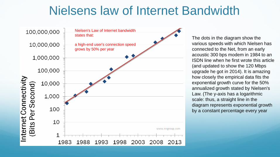
Nielsens law of Internet Bandwidth
The dots in the diagram show the
various speeds with which Nielsen has
connected to the Net, from an early
acoustic 300 bps modem in 1984 to an
ISDN line when he first wrote this article
(and updated to show the 120 Mbps
upgrade he got in 2014). It is amazing
how closely the empirical data fits the
exponential growth curve for the 50%
annualized growth stated by Nielsen's
Law. (The y-axis has a logarithmic
scale: thus, a straight line in the
diagram represents exponential growth
by a constant percentage every year
Nielsen's Law of Internet bandwidth
states that:
a high-end user's connection speed
grows by 50% per year

Cisco Confidential 11
A look into the past may predict the future

Consumer Needs Driving New Services
A Multi-screen Video Experience
High Bandwidth for Next-gen Services
Support an Increasing Variety of Services and Common Experiences –
At Any Time, Anywhere and on Any Device
Social TV and Companion Services
-20
30
80
2000 2005 2010 2015Exa
byte
s p
er
mo
nth
Managed and Unmanaged Devices
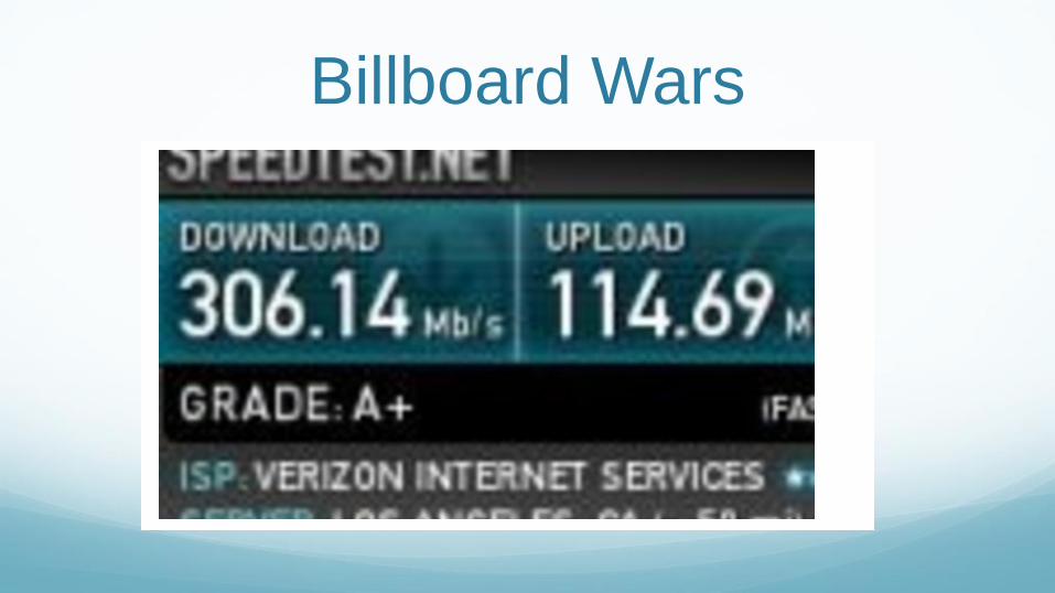
Billboard Wars

IoE and IoT is driving Web 3.0
Click on image to view YouTube Video

DOCSIS Today Review
DOCSIS 3.1 Drivers – The need for more speed
DOCSIS 3.1 High Level Overview
DOCSIS 3.1 Channel Anatomy
DOCSIS 3.1 Spectrum Options and Deployment Examples
Agenda

What is DOCSIS 3.1?
Answer: The latest Data Over Cable Service Interface Specifications
CableLabs® released version I01 of the new spec in late October, 2013, version I02 in March, 2014, and version I03 in June, 2014.
(available for download at http://www.cablelabs.com/specs/specification-search/?cat=docsis)

DOCSIS 3.1 Background Goals
Backwards compatibility with DOCSIS
3.0, 2.0, & 1.1
Better spectral efficiency (more bits/Hz)
Higher Capacity than D3.0
Deployable in today’s networks
Technology
OFDM, OFDMA, LDPC
Expanded downstream and upstream
spectrum
Improved energy efficiency
This will allow DOCSIS 3.1 to support
services competitive with FTTH. Deployable in today’s HFC networks!

Backwards compatibility DOCSIS 3.1 devices will simultaneously support
legacy SC-QAM channels and OFDM channels
Devices will support bonding between OFDM and
SC-QAM in order to aggregate that capacity and
provide an incremental and orderly migration
The time division nature of the existing DOCSIS
upstream allows for legacy and OFDMA to be time
multiplexed
Allows a gradual and evolutionary introduction of
DOCSIS 3.1

D3.1 Improved performance
New physical layer (PHY) technology: OFDM (orthogonal frequency division
multiplex) and OFDMA (orthogonal frequency division multiple access)
Better spectral efficiency than SC-QAM
Multiple subcarriers per ch
Each subcarrier is a QAM signal
Better forward error correction (FEC): low density parity check (LDPC)
More robust than the Viterbi/Reed-Solomon FEC used in earlier versions of DOCSIS
5-6dB SNR Gain

D3.1 Improved performance
Expanded downstream and upstream RF spectrum usage
Downstream: 258 MHz to 1218 MHz, optional to 1794 MHz (and 108 MHz on lower end)
Upstream: 5 MHz to 204 MHz
DOCSIS 3.1 supports larger blocks of spectrum
Downstream supports at least 2x192MHz blocks
Plus support for SC QAMs
US Supports at least 2x96MHz blocks

Example DOCSIS 3.1 SNR/MER requirements Bits per Hz
Modulation order MER/SNR
256-QAM 29~30 dB 8
512-QAM 31~33 dB 9
1024-QAM 34~36 dB 10
2048-QAM 37~39 dB 11
4096-QAM 40~42 dB 12
Spectral Efficiency – The amount of bits that fit into a given RF channel bandwidth
• Assume minimum of 10 b/p/Hz, 192MHz block = ~ 1.9Gbps
• Compare to D3.0, 32 QAMs = 192MHz = ~1.5Gbps
D3.1 Improved performance

DOCSIS 3.1 Frequency Plans • HFC Plant Expansion Options
• Extended Frequency Plans
• Downstream
• [108MHz] 258MHz - 1218MHz [1794MHz] [ ] = Optional
• Upstream
• 5MHz-42MHz /65MHz /85MHz /108MHz /204MHz
5 42 85 117 204 258 1218 1794
Mandatory
Optional Upstream
Optional Downstream

OFDM A D3.1 OFDM Channel is comprised of individual subcarriers
Spaced at either 25KHz or 50KHz
Each subcarrier carries a small percentage of the total data payload at a very low data rate.
The aggregate of all of the subcarriers’ data rates comprises the total data payload.
This variation of FDM is known as orthogonal frequency division multiplexing, or OFDM, and is used
in the DOCSIS 3.1 downstream
The upstream counterpart is called OFDMA, or orthogonal frequency division multiple access.
Time division multiple access (TDMA) also is used, for a two-dimensional sharing of the
upstream channel.

OFDM One SC-QAM signal within one channel
One Channel
Multiple subcarriers within one channel
One Channel
Imagine transmitting a large number of
individual very narrow-bandwidth QAM
signals – dozens, hundreds or even
thousands – within a single channel.
Each narrow-bandwidth QAM signal is
called a subcarrier.
The 6 MHz-wide downstream
channel slots defined by the North
American CEA-542-D frequency
plan can each accommodate one
analog NTSC TV signal or one SC-
QAM signal.

OFDM: Analogy
Am
plit
ude
0
0.2
0.4
0.6
0.8
1.0
- 0.2
- 0.4
Frequency
1/TU

OFDM With OFDM, the concept of a 6 MHz or 8 MHz channel is no longer necessary.
A DOCSIS 3.1 downstream OFDM channel’s bandwidth is up to 192 MHz
The upstream OFDMA channel bandwidth is up to 96 MHz
Narrower OFDM and OFDMA channel bandwidths are possible by excluding or
“nulling” subcarriers
Downstream channel bandwidths: 24 MHz to 192 MHz
Upstream channel bandwidths: 6.4 MHz (25 kHz subcarrier spacing) or 10
MHz (50 kHz subcarrier spacing) to 96 MHz

Frequency
1024 QAM
SNR
256 QAM 1024 QAM Suppressed 1024 QAM 512 QAM 256 QAM
OFDM – Individual Sub-Carrier Management
Ingressor

OFDM
Optimizes channel capacity
Granular spectrum allocation
Maximize cross industry investments
Consistency with other standards
OFDM is a proven technology that
enjoys widespread use:

LDPC FEC
DOCSIS 3.1 uses a form of FEC
known as LDPC
LDPC = low density parity check
The concept of LDPC was introduced by
Robert G. Gallager in his 1960 Sc.D.
thesis at MIT. Because of encoder and
decoder complexity, it wasn’t practical to
implement LDPC until relatively recently
More robust than Viterbi/Reed-
Solomon FEC
Provides up to 5~6 dB gain compared to
Viterbi/RS FEC

D 3.1 Higher modulation orders: downstream
CMTS
downstream
transmit
Cable
modem
downstream
receive
Bits
per
symbol
MUST 16-QAM 16-QAM 4
MUST 64-QAM 64-QAM 6
MUST 128-QAM 128-QAM 7
MUST 256-QAM 256-QAM 8
MUST 512-QAM 512-QAM 9
MUST 1024-QAM 1024-QAM 10
MUST 2048-QAM 2048-QAM 11
MUST 4096-QAM 4096-QAM 12
MAY 8192-QAM 8192-QAM 13
MAY 16384-QAM 16384-QAM 14

D3.1 Approximate downstream speeds
Modulation
order
25 kHz
subcarrier
spacing
50 kHz
subcarrier
spacing
256-QAM 1.26 Gbps 1.20 Gbps
512-QAM 1.42 Gbps 1.35 Gbps
1024-QAM 1.58 Gbps 1.50 Gbps
2048-QAM 1.73 Gbps 1.65 Gbps
4096-QAM 1.89 Gbps 1.80 Gbps
8192-QAM 2.05 Gbps 1.96 Gbps
16384-QAM 2.21 Gbps 2.11 Gbps
Single 192 MHz OFDM channel (full channel, no exclusions)
8192-QAM and 16384-
QAM are optional, and
may not be practical in
most of today’s plants

D3.1 Higher modulation orders: upstream
Cable modem upstream
transmit
CMTS upstream receive Bits per symbol
MUST QPSK QPSK 2
MUST 8-QAM 8-QAM 3
MUST 16-QAM 16-QAM 4
MUST 32-QAM 32-QAM 5
MUST 64-QAM 64-QAM 6
MUST 128-QAM 128-QAM 7
MUST 256-QAM 256-QAM 8
MUST 512-QAM 512-QAM 9
MUST 1024-QAM 1024-QAM 10
MUST 2048-QAM — 11
MUST 4096-QAM — 12
SHOULD — 2048-QAM 11
SHOULD — 4096-QAM 12

D 3.1 Approximate upstream speeds
Modulation order 25 kHz subcarrier
spacing
50 kHz subcarrier
spacing
64-QAM 0.47 Gbps 0.46 Gbps
128-QAM 0.55 Gbps 0.53 Gbps
256-QAM 0.63 Gbps 0.61 Gbps
512-QAM 0.71 Gbps 0.69 Gbps
1024-QAM 0.78 Gbps 0.76 Gbps
2048-QAM 0.86 Gbps 0.84 Gbps
4096-QAM 0.94 Gbps 0.91 Gbps
Single 96 MHz OFDMA channel (full channel, no exclusions)

Full spectrum DOCSIS 3.1 BW Potential
OFDM OFDM OFDM
1218 MHz 1002 MHz 258 MHz 204 MHz 750 MHz 870 MHz 5 MHz
OFDM
192 MHz 192 MHz 192 MHz
Two 96 MHz
OFDMA
channels OFDM OFDM OFDM
192 MHz 192 MHz
...to 1794 MHz
QAM BW
Gbps
64 .94
256 1.26
512 1.42
1024 1.56
2048 1.72
4096 1.88
QAM BW Gbps
256 6.3
512 7.1
1024 7.8
2048 8.6
4096 9.4

Plant performance?
Example DOCSIS
3.1 SNR/MER
requirements
Modulation
order
MER/SNR
256-QAM 29~30 dB
512-QAM 31~33 dB
1024-QAM 34~36 dB
2048-QAM 37~39 dB
4096-QAM 40~42 dB
One cable operator’s analysis showed at
least 8 dB variation in downstream SNR
(MER) among millions of modems:

Downstream profiles Downstream profiles support the transmission of
different modulation orders to different modems
The downstream profiles feature is always used,
even if the feature is configured for just one profile
Multiple downstream profiles could enable operators
to leverage SNR/MER variation to improve system
capacity
Example with four profiles: A: Worst (say, mostly 256-QAM) B: Average (say, mostly 1024-QAM) C: Better (say, mostly 2048-QAM) D: Best (say, mostly 4096-QAM)
Worst
Case
Average
Case
Best
Case Better
Case

Profile Management
Single-profile system works by providing worst service to all CMs
Multi-profile system works by providing best overall service to all CMs
Profile defines bit loading for each subcarrier
CM reports MER/SNR and RX power of each subcarrier
CM can test its ability to receive unused profiles and report result
CMTS updates and publishes profiles
CMTS assigns CMs to profiles

Upstream Profiles
Efficient profiles are assigned to CMs with good SNR, robust profiles to CMs
with lower SNR
No energy is transmitted in excluded subcarriers or zero value subcarriers
Excluded subcarriers skip over narrowband interferers, very noisy spectrum,
and legacy carriers
CM required to support 2 profiles per OFDMA channel at a time; CMTS
required to support 4 profiles at one time

DOCSIS 3.1 Key Takeaways
Introduces a new FEC to DOCSIS (LDPC)
Better SNR performance
More Bits per Hz
More overall capacity than D3.0
Larger blocks of frequency Spectrum
Introduces a New Modulation to DOCSIS (OFDM)
Multiple Modulation Profiles
Backwards Compatible

DOCSIS Today Review
DOCSIS 3.1 Drivers – The need for more speed
DOCSIS 3.1 High Level Overview
DOCSIS 3.1 Channel Anatomy
DOCSIS 3.1 Spectrum Options and Deployment Examples
Agenda

Anatomy of a downstream OFDM channel
192 MHz channel bandwidth, including 1 MHz wide guard band on each end.
190 MHz encompassed spectrum
25 kHz subcarrier spacing: 7600 subcarriers (8K FFT)
50 kHz subcarrier spacing: 3800 subcarriers (4K FFT)
Since the guard bands in this example total 2 MHz out of 192 MHz, the equivalent
excess bandwidth or “alpha” is (2/192) x 100 ≈ 1%, compared to 12% for DOCSIS 3.0
and earlier 256-QAM SC-QAM.

Anatomy of a downstream OFDM channel
192 MHz channel bandwidth, including 1 MHz wide guard band on each end
190 MHz
Exclusion bands may be created within an
OFDM channel for problems such as strong
ingress (e.g., LTE interference), or for the
carriage of legacy SC-QAM signals.
An exclusion band is a set of contiguous subcarriers within the OFDM channel
bandwidth that are set to zero-value by the transmitter to avoid interference or to
accommodate co-existing transmissions such as legacy SC-QAM signals.

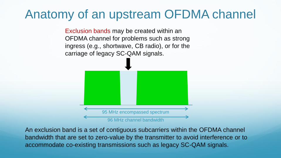
Anatomy of an upstream OFDMA channel
95 MHz encompassed spectrum
25 kHz subcarrier spacing: 3800 subcarriers (4K FFT)
50 kHz subcarrier spacing: 1900 subcarriers (2K FFT)
96 MHz channel bandwidth
1 MHz guard
band
1 MHz guard
band
Anatomy of an upstream OFDMA channel
95 MHz encompassed spectrum
Exclusion bands may be created within an
OFDMA channel for problems such as strong
ingress (e.g., shortwave, CB radio), or for the
carriage of legacy SC-QAM signals.
An exclusion band is a set of contiguous subcarriers within the OFDMA channel
bandwidth that are set to zero-value by the transmitter to avoid interference or to
accommodate co-existing transmissions such as legacy SC-QAM signals.
96 MHz channel bandwidth

Anatomy of an upstream OFDMA channel
96 MHz channel bandwidth
95 MHz encompassed spectrum
Exclusion bands may be created within an
OFDMA channel for problems such as strong
ingress (e.g., shortwave, CB radio), or for the
carriage of legacy SC-QAM signals.
An exclusion band is a set of contiguous subcarriers within the OFDMA channel
bandwidth that are set to zero-value by the transmitter to avoid interference or to
accommodate co-existing transmissions such as legacy SC-QAM signals.

Anatomy of an upstream OFDMA channel
95 MHz encompassed spectrum
OFDMA is a multi-user version of OFDM,
and assigns subsets of subcarriers to
individual CMs.
96 MHz channel bandwidth
CM2 CM3 CM5 CM1 CM4
In this example, five
modems are
transmitting
simultaneously within
the same 96 MHz
bandwidth OFDMA
channel. The different
colors represent
subsets of the
channel’s subcarriers
assigned to each
modem.

DOCSIS Today Review
DOCSIS 3.1 Drivers – The need for more speed
DOCSIS 3.1 High Level Overview
DOCSIS 3.1 Channel Anatomy
DOCSIS 3.1 Spectrum Options and Deployment Examples
Agenda

Additional example spectrum options
Downstream spectrum options:
1. Initially use 750/862/1002 MHz plant (6 Gbps)
2. Next step is 1218 MHz (7+ Gbps, amp upgrade)
3. Long-term is 1794 MHz (10+ Gbps, tap upgrade)
Upstream spectrum options:
1. Initially use sub-split (42/65 MHz, 200 Mbps)
2. Next step is mid-split (85 MHz, 400 Mbps)
3. Long-term is high-split. (204 MHz, 1 Gbps)

DOCSIS 3.1 downstream frequency usage
DOCSIS 3.1 downstream: 258 MHz to 1218 MHz
1794 MHz 1218 MHz 258 MHz 108 MHz 750 MHz 1002 MHz
54 MHz

DOCSIS 3.1 downstream frequency usage
DOCSIS 3.1 downstream: 258 MHz to 1218 MHz
Optional 108 MHz lower end
Optional 1794 MHz upper end
Must support a minimum of two 192 MHz-wide OFDM channels in the downstream
1794 MHz 1218 MHz 258 MHz 108 MHz 750 MHz 1002 MHz
54 MHz

DOCSIS 3.1 upstream frequency usage
DOCSIS 3.1 upstream: 5 MHz to 204 MHz
258 MHz 117 MHz 42 MHz 65 MHz 85 MHz 5 MHz 204 MHz

DOCSIS 3.1 upstream frequency usage
DOCSIS 3.1 upstream: 5 MHz to 204 MHz
Also must support 5 MHz to 42 MHz, 5 MHz to 65 MHz, 5 MHz to 85 MHz, and 5 MHz to 117
MHz
Must support a minimum of two 96 MHz-wide OFDMA channels in the upstream
258 MHz 117 MHz 42 MHz 65 MHz 85 MHz 5 MHz 204 MHz

DOCSIS 3.1 upstream frequency usage
Using time division duplexing, legacy upstream SC-QAM signals can share the return
spectrum with full-bandwidth OFDMA.
A DOCSIS 3.0 (or earlier) modem transmits when DOCSIS 3.1 modems are not transmitting
108 MHz 42 MHz 54 MHz 88 MHz 5 MHz
Downstream
Upstream
SC-QAM

DOCSIS 3.1 upstream frequency usage
Using time division duplexing, legacy upstream SC-QAM signals can share the return
spectrum with full-bandwidth OFDMA.
A DOCSIS 3.1 modem transmits when legacy modems are not transmitting
108 MHz 42 MHz 54 MHz 88 MHz 5 MHz
Downstream
Upstream
OFDMA

DOCSIS 3.1 upstream frequency usage
Alternatively, the OFDMA channel can be configured with an exclusion band to
accommodate legacy SC-QAM channels, while the OFDMA signal occupies the rest of
the spectrum.
This would allow legacy and DOCSIS 3.1 modems to use the spectrum simultaneously
108 MHz 42 MHz 54 MHz 88 MHz 5 MHz
Downstream
Upstream
OFDMA +
SC-QAM

DOCSIS 3.1 deployment example
The OFDM channel can be located in available spectrum
Windowing can be used to sharpen the spectral edges of the OFDM signal
Legacy DOCSIS SC-QAM and DOCSIS 3.1 OFDM can be bonded
OFDM
One 192 MHz OFDM channel
Legacy digital video
SC-QAM signals
Legacy DOCSIS
SC-QAM signals

DOCSIS 3.1 deployment example
Excluded subcarriers (“nulling”) can be used to facilitate coexistence of an OFDM
channel with legacy SC-QAM signals
The OFDM subcarriers can be located in available spectrum
As before, legacy DOCSIS SC-QAM and DOCSIS 3.1 OFDM can be bonded
OFDM OFDM
One 192 MHz OFDM channel
Legacy DOCSIS SC-QAM signals
in exclusion band within OFDM channel
Legacy digital video
SC-QAM signals
Legacy digital video
SC-QAM signals
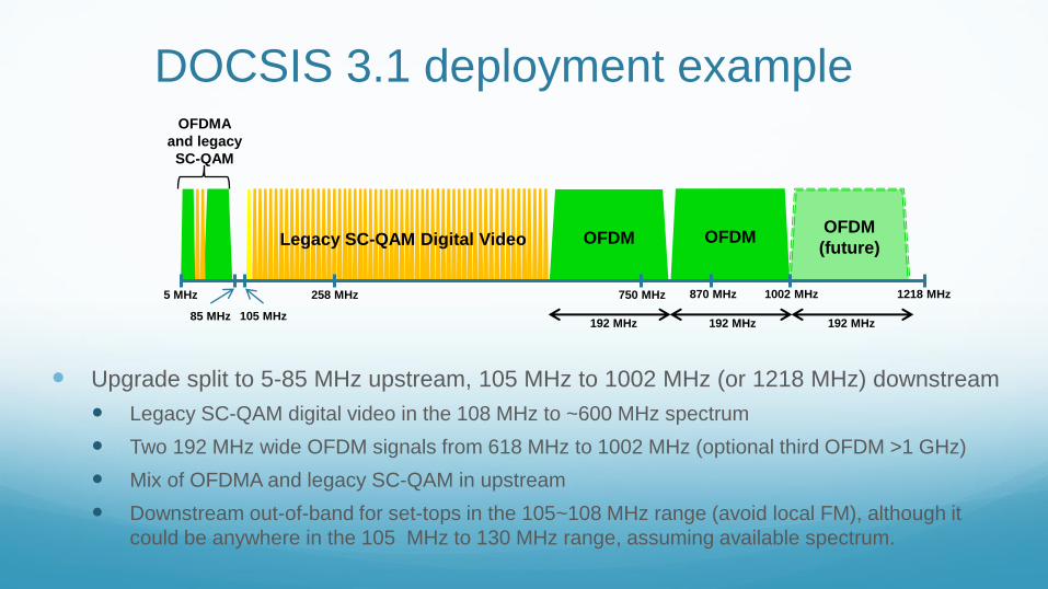
DOCSIS 3.1 deployment example
Upgrade split to 5-85 MHz upstream, 105 MHz to 1002 MHz (or 1218 MHz) downstream
Legacy SC-QAM digital video in the 108 MHz to ~600 MHz spectrum
Two 192 MHz wide OFDM signals from 618 MHz to 1002 MHz (optional third OFDM >1 GHz)
Mix of OFDMA and legacy SC-QAM in upstream
Downstream out-of-band for set-tops in the 105~108 MHz range (avoid local FM), although it
could be anywhere in the 105 MHz to 130 MHz range, assuming available spectrum.
OFDM
1218 MHz 1002 MHz 258 MHz
105 MHz
750 MHz 870 MHz 5 MHz
85 MHz
OFDM OFDM
(future)
192 MHz 192 MHz 192 MHz
Legacy SC-QAM Digital Video
OFDMA
and legacy
SC-QAM

DOCSIS 3.1 deployment example
Upgrade split to 5-85 MHz upstream, 105 MHz to 1218 MHz downstream
Legacy SC-QAM digital video in the 108 MHz to 258 MHz spectrum
Five 192 MHz wide OFDM signals from 258 MHz to 1218 MHz
Mix of OFDMA and legacy SC-QAM in upstream
Downstream out-of-band for set-tops in the 105~108 MHz range (avoid local FM), although it
could be anywhere in the 105 MHz to 130 MHz range, assuming available spectrum.
OFDM
1218 MHz 1002 MHz 258 MHz
105 MHz
750 MHz 870 MHz 5 MHz
85 MHz
OFDM
192 MHz 192 MHz 192 MHz
Legacy SC-QAM
digital video
OFDMA
and legacy
SC-QAM
OFDM OFDM OFDM
192 MHz 192 MHz

Full spectrum DOCSIS 3.1 deployment example
Upgrade split to 5-204 MHz upstream, 258 MHz to 1218 MHz downstream (optionally
to 1794 MHz)
Five 192 MHz wide OFDM signals from 258 MHz to 1218 MHz
Optionally another three 192 MHz wide OFDM signals between 1218 MHz and 1794 MHz
Two 96 MHz wide OFDMA signals in the 5 MHz to 204 MHz spectrum
OFDM OFDM OFDM
1218 MHz 1002 MHz 258 MHz 204 MHz 750 MHz 870 MHz 5 MHz
OFDM
192 MHz 192 MHz 192 MHz
Two 96 MHz
OFDMA
channels OFDM OFDM OFDM
192 MHz 192 MHz
...to 1794 MHz

Summary • New PHY layer: OFDM, OFDMA, and LDPC
• Higher modulation orders
• New spectrum usage options
• Takes DOCSIS to full-spectrum capability
• Cost-effectively scales to 10+ Gbps in the downstream, 2+ Gbps in the
upstream
• FTTH equivalent at lower price point on an existing HFC plant
• Deployable in today’s HFC networks

Cisco Confidential 65
Thank You


