DESIGN OF NORMALIZED SUBBAND ADAPTIVE FILTER FOR
ACOUSTIC ECHO CANCELLATION
Pavya.S, Graduate Student Member IEEE,
K.S.Rangasamy college of technology,
Tiruchengode,tamilnadu,India
P.Babu,Associate professor(ECE),
K.S. Rangasamy College of Technology,
Tiruchengode, Tamilnadu, India
ABSTRACT: In hands-free telephones and
teleconferencing systems, acoustic echo cancellers are
required, which are often implemented by adaptive
filters. In these applications, the speech input signal of
the adaptive filter is highly correlated and the impulse
response of the echo path is very long. These
characteristics will slow down the convergence rate of
the adaptive filter if the well-known normalized
leastmean- square (NLMS) algorithm is used. The
normalized subband adaptive filter (NSAF) offers a
good solution to this problem because of its
decorrelating property. This paper proposes a VHDL
implementation of normalized subband adaptive filter
structure(NSAF) adaptive algorithm.the experiment
result shows that the power consumed by subband is lower than that of full band.
Index Terms — Acoustic echo canceller, adaptive
combination, normalized subband adaptive filter
(NSAF), hands-free telephone, teleconferencing system
Cascade intergrator-comb filter (CIC).
I.INTRODUCTION
A common problem encountered in hands-free
telephones and teleconferencing systems is the presence
of echoes which are generated acoustically by the
coupling between the loudspeaker and the microphone
via the impulse response of a room [1]. Removal of
these echoes requires the precise knowledge of the
impulse response of the acoustic echo path, which may
be time varying. In recent years, there has been a great interest in the use of adaptive filters as acoustic echo
cancellers to remove echoes [2], [3]. An adaptive filter
can be characterized by its structure and adaptive
filtering algorithm [4]. The transversal filter with the
well-known normalized least-mean-square (NLMS)
algorithm is one of the most popular adaptive filters
because of its simplicity and robust performance [5],
[6]. In acoustic echo cancellation (AEC) applications,
however, the speech input signal of the adaptive filter is
highly correlated and the impulse response of the
acoustic echo path is very long. These two
characteristics will slow down the convergence rate of
the acoustic echo canceller if the NLMS-based adaptive
filter is used to remove echoes.
One technique to solve the above problem is
subband adaptive filtering. In conventional subband
adaptive filters (SAFs), each subband uses an individual
adaptive subfilter in its own adaptation loop, which
decreases the convergence rate of SAFs because of the
aliasing and band-edge effects [7]. To solve these
structural problems, a family of SAFs based on a new
structure has been proposed [8]–[10]. In [8], Courville
and Duhamel derived an SAF using a weighted
criterion. Based on the polyphase decomposition,
Pradhan and Reddy [9] derived another SAF using a
similar weighted criterion. In [10], Lee and Gan
presented a normalized SAF (NSAF) from the principle of minimum disturbance, with its complexity close to
that of the NLMS-based adaptive filter. The NSAF can
be viewed as a subband generalization of the
NLMSbased adaptive filter. Its central idea is to use the
subband signals, normalized by their respective
subband input variances, to update the tap weights of a
fullband adaptive filter. This strategy leads to the
decorrelating property of the NSAF [11]. Although
these SAFs can obtain fast convergence rate when
applied to AEC applications, they all require a tradeoff
between fast convergence rate and small steady-state
mean-square error (MSE) because of the use of a fixed
stepsize. Several studies have shown that the set-
membership, variable regularization parameter, and
variable step-size parameter versions of the NSAF can
offer possible schemes to overcome the conflicting
requirements of fast convergence rate and small steady-state MSE [12]–[14]. However, they all need to
estimate the system noise power in advance, which
increases the complexity of the system.
Recently, an adaptive combination of fullband
adaptive filters has been proposed in [15], and its mean
square error has been analyzed in [16]. The merit of
this combination is that it can obtain both fast
convergence rate and small steady-state MSE without
estimate of the system noise power. More recently, a
combination of subband adaptive filters for AEC has
been proposed [17], which is based on a conventional
subband structure. In this paper, we propose a new
Pavya S et al ,Int.J.Computer Technology & Applications,Vol 3 (3), 1232-1236
IJCTA | MAY-JUNE 2012 Available [email protected]
1232
ISSN:2229-6093

subband adaptive combination scheme to deal with the
tradeoff problem encountered in acoustic echo
cancellers which are implemented by NSAFs. The
proposed combination is carried out in subband domain
and the mixing parameter that controls the combination
is adapted by means of a stochastic gradient algorithm
which employs the sum of squared subband errors as
the cost function. The section is splited as II.NSAF
structure III.Filter Bank IV.CIC decimator V.CIC interpolator VI.simulation results
Fig 1: Block Diagram of NSAF
II.NSAF STRUCTURE An N-channel analysis filter bank is a structure
transforming an input signal to a set of N subband
signals. A corresponding N-channel synthesis filter
bank transforms N subband channels to a full band
signal, in other words the inverse operation takes place. All subbands have equal bandwidth and the same
decimation and interpolation factors.
In this architecture both the microphone
signal d(n) and the far-end signal u(n) are partitioned
into N sub band signals via the analysis filters Hi(z ),i=
0,1, …N-1 The sub band signals di( n) and yi( n) for i =
0,1,…N −1 are all critically decimated to a lower
sampling rate. The decimated subband error signals are
then defined as eid(n)=di,d(n)-yi,d(n) , i=0,1,…..,N-1
Here we use the variable n and k to index the original
and decimated sequences.
III.FILTER BANK A filter bank is a set of bandpass filters with a
common input for the analysis filter bank or a summed
output for the synthesis filter bank.Figure 2 shows an
N-channel (or N-band) filter bank using z-domain
notation, where Hi(z) and Gi(z) are the analysis and
Fig 2: NSAF Structure
synthesis filters, respectively, and the variable i = 0, 1, .
. .,N – 1 is used as the subband index. The analysis
filter bank partitions the incoming signal X(z) into N
subband signals Xi(z), each occupying a portion of the
original frequency band. The synthesis filter bank
reconstructs the output signal Y(z) from N subband
signals Yi(z) to approximate the input signal.
A filter bank is called a uniform filter bank if
the center frequencies of bandpass filters are uniformly
spaced and all filters have equal bandwidth. By decomposing a fullband signal using an N-channel
uniform filter bank, each subband signal Xi(z) contains
only 1/N of the original spectral band. Since the
bandwidth of the subband signals Xi(z) is 1/N of the
original signal X(z), these subband signals can be
decimated to 1/N of the original sampling rate while
preserving the original information. A filter bank is
called a critically (or maximally) decimated filter
bank,if the decimation factor is equal to the number of
subbands, i.e. D = N. Critical decimation preserves the
effective sampling rate with N decimated subband
signals, Xi,D(z), each with 1/N of the original sampling
+
_
Echo path Analysis
filter
CIC
decimator
Noise
Analysis
filter
Adaptive
filter
CIC
decimator
Output bit error
ratio
Synthesis
filter
CIC
interpolator
+
Σ i/p
Pavya S et al ,Int.J.Computer Technology & Applications,Vol 3 (3), 1232-1236
IJCTA | MAY-JUNE 2012 Available [email protected]
1233
ISSN:2229-6093

rate, so that the total number of subband samples is
identical to that of the fullband signal X(z). In the
synthesis section, the decimated subband signals
Xi,D(z) are interpolated by the same factor before being
combined by the synthesis filter bank. Therefore, the
original sampling rate is restored in the reconstructed
fullband signal Y(z).
IV.CIC DECIMATOR
Cascaded integrator-comb (CIC), or
Hogenauer filters, are multirate filters used for realizing
large sample rate changes in digital systems. Both
decimation and interpolation structures are supported
by the Core. CIC filters are multiplierless structures,
consisting of only adders, subtractors and registers.
They are typically employed in applications that have a
large excess sample rate. That is, the system sample
rate is much larger than the bandwidth occupied by the
signal. CIC filters are frequently used in digital down-
converters (DDCs) and digital up-converters. Figure 1
shows the basic structure for a CIC decimation filter.
The integrator section consists of N ideal integrator
stages operating at the high sampling rate fs. Each stage
is implemented as a one-pole filter with a unity
feedback coefficient The transfer functions for a single integrator is
Hi(z)=1/1-z-1
(1)
Fig 3: CIC Decimator
The comb section operates at the low sampling
rate fs/R where R is the integer rate change factor. This
section consists of comb stages with a differential delay
of M samples per stage. The differential delay is a filter
design parameter used to control the filter’s frequency response. M is restricted to be either 1 or 2. The transfer
function for a single comb stage, referenced to the high
input sample rate is
Hc(z)=1-zRM
(2)
There is a rate change switch (indicated in the
figure as the decimation function) between the two
filter sections. The decimator subsamples the output of
the last integrator stage, reducing the sample rate from
fs to fs/R. The system transfer function for the
composite CIC filter, referenced to the high sampling
rate, is
H(z)= Hi(z) Hc(z)
=(1-zRM
)N/(1-z
-1)
N
=[ 𝑧𝑅𝑀−1𝑘=0
-k]N
From the last form of the CIC transfer
function, we observe that the CIC filter is equivalent to
a cascade of N uniform FIR (finite impulse response)
filter stages with unit coefficients; that is, the filter is
equivalent to a cascade of N box-car filters. The CIC
decimator is actually implemented using the pipelined
architecture The pipeline registers P0, P1, P2 and P3
shorten the critical path through the differentiator
cascade
V.CIC INTERPOLATOR Exchanging the integrator cascade with the
differentiator cascade, as shown in Figure 3, produces a
CIC interpolator. Data is presented to the filter at the
rate fs/R where it is processed by the differentiators.
The rate expander in the figure causes a rate increase by
a factor R by inserting R-1 zero valued samples between consecutive samples of the comb section
output. The up-sampled and filtered data stream is
presented to the output at the sample rate fs. Just like
the CIC decimator, the Core implementation uses a
pipelined structure.
Fig 4:CIC Interpolator
VI.SIMULATION RESULT Analysis and Synthesis prototype filters with
length 16 taps is choosen. For filter design we use a
method from [3]. The decimation factor L is 2. All
calculation are based on a sampling rate of 8 kHz.
The echo-path is modeled by FIR-filter. The
FIR impulse response has a reverberation time of 72 ms
and was measured in a large car. As excitation signal
we use colored noise, which is generated by first order
IIR filtering of white noise, and speech.
Here five stage decimator and interpolator is
used. It Supports decimation and interpolation rate
changes between 8 and 16,383. Number of CIC stages
programmable between 1 and 8.Multiplierless filter
architecture is ideal for systems. Output of the decimator is given in fig 6.output is nothing but the
o/p
I I I C C C R
i/p
o/p
C C C I I I R
i/p
Pavya S et al ,Int.J.Computer Technology & Applications,Vol 3 (3), 1232-1236
IJCTA | MAY-JUNE 2012 Available [email protected]
1234
ISSN:2229-6093
two’s complement of the filter output.fig 7 discuss the
output of the interpolator which is nothing but zero
padding and shiffting right by 2.fig 8 gives the output
of the synthesis filter which is nothing but the
reconstructed output 80 percent of the input is obtained
using the bit error ratio.power is calculated using
synopsys tool and is shown in fig 9.
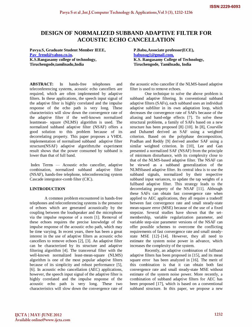
Fig 5: vhdl output analysis filter (length=16, direct form
fir filter)
Fig 6: vhdl output for decimator(decimation factor=5)
Fig 7:vhdl output for interpolator(interpolation
factor=5)
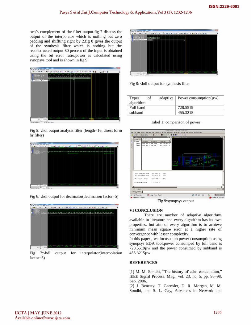
Fig 8: vhdl output for synthesis filter
Types of adaptive
algorithm
Power consumption(µw)
Full band 728.5519
subband 455.3215
Tabel 1: comparison of power
Fig 9:synopsys output
VI CONCLUSION There are number of adaptive algorithms
available in literature and every algorithm has its own
properties, but aim of every algorithm is to achieve
minimum mean square error at a higher rate of
convergence with lesser complexity.
In this paper , we focused on power consumption using
synopsys EDA tool.power consumped by full band is
728.5519µw and the power consumed by subband is
455.3215µw.
REFERENCES
[1] M. M. Sondhi, ―The history of echo cancellation,‖
IEEE Signal Process. Mag., vol. 23, no. 5, pp. 95–98,
Sep. 2006.
[2] J. Benesty, T. Gaensler, D. R. Morgan, M. M.
Sondhi, and S. L. Gay, Advances in Network and
Pavya S et al ,Int.J.Computer Technology & Applications,Vol 3 (3), 1232-1236
IJCTA | MAY-JUNE 2012 Available [email protected]
1235
ISSN:2229-6093

Acoustic Echo Cancellation. Berlin, Germany:
Springer-Verlag, 2001.
[3] C. C. Kao, ―Design of echo cancellation and noise
elimination for speech enhancement,‖ IEEE Trans.
Consumer Electronics, vol. 49, no. 4, pp.1468–1473,
Nov. 2003.
[4] H. Ding, ―Fast affine projection adaptation
algorithms with stable and robust symmetric linear
system slovers,‖ IEEE Trans. Signal Process., vol. 55, no. 5, pp. 1730–1740, May 2007.
[5] W. S. Gan, S. Mitra, and S. M. Kuo, ―Adaptive
feedback active noise control headset: implementation,
evaluation and its extensions,‖ IEEE Trans. Consumer
Electronics, vol. 51, no. 3, pp.975–982, Aug. 2005.
[6] A. H. Sayed, Adaptive Filters. New York: Wiley,
2008.
[7] K. A. Lee, W. S. Gan, and S. M. Kuo, Subband
Adaptive Filtering: Theory and Implementation.
Hoboken, NJ: Wiley, 2009.
[8] M. D. Courville and P. Duhamel, ―Adaptive
filtering in subbands using a weighted criterion,‖ IEEE
Trans. Signal Process., vol. 46, no. 9, pp. 2359–2371,
Sep. 1998.
[9] S. S. Pradhan and V. U. Reddy, ―A new approach to
subband adaptive filtering,‖ IEEE Trans. Signal
Process., vol. 47, no. 3, pp. 655–664, Mar. 1999.
[10] K. A. Lee and W. S. Gan, ―Improving convergence
of the NLMS algorithm using constrained subband
updates,‖ IEEE Signal Process. Lett., vol. 11, no. 9, pp.
736–739 , Sep. 2004.
[11] K. A. Lee and W. S. Gan, ― Inherent decorrelating
and least perturbation properties of the normalized
subband adaptive filter,‖ IEEE Trans. Signal Process.,
vol. 54, no. 11, pp. 4475–4480, Nov. 2006.
[12] M. S. E. Abadi and J. H. Husøy, ―Selective partial
update and setmembership subband adaptive filters,‖
Signal Processing, vol. 88, no. 10, pp. 2463–2471, Oct. 2008.
[13] J. Ni and F. Li, ―A variable regularization matrix
normalized subband adaptive filter,‖ IEEE Signal
Process. Lett., vol. 16, no. 2, pp. 105–108, Feb. 2009.
[14] J. Ni and F. Li, ―A variable step-size matrix
normalized subband adaptive filter,‖ IEEE Trans.
Audio, Speech, Lang. Process., to be published, DOI:
10.1109/TASL.2009.2032948.
[15] J. Arenas-García, M. Martínez-Ramón, A. Navia-
Vázquez, and A. R. Figueiras-Vidal, ―Plant
identification via adaptive combination of transversal
filters,‖ Signal Process., vol. 86, pp. 2430–2438, 2006.
[16] J. Arenas-Garcia, A. R. Figueiras-Vidal, and A. H.
Sayed, ―Mean-square performance of a convex
combination of two adaptive filters,‖ IEEE Trans.
Signal Process., vol. 54, no. 3, pp. 1078–1090, Mar.
2006.
[17] L. A. Azpicueta-Ruiz, A. R. Figueiras-Vidal, and
J. Arenas-García, ―Acoustic echo cancellation in
frequency domain using combinations of filters,‖ in
19th Int. Congress on Acoustics (ICA), Madrid, Sep.
2007.
[18] N. J. Bershad, J. C. M. Bermudez and J.-Y.
Tourneret, ―An affine combination of two LMS
adaptive filters —Transient mean-square analysis,‖
IEEE Trans. Signal Process., vol. 56, no. 5, pp. 1853–
1864, May 2008.
[19] M. R. Petraglia, P. B. Batalheiro, ―Nonuniform
subband adaptive filtering with critical sampling,‖
IEEE Trans. Signal Process., vol. 56, no. 2, pp. 565–
575, 2008.
[20] J. Arenas-Garcia and A. R. Figueiras-Vidal,
―Adaptive combination of proportionate filters for
sparse echo cancellation,‖ IEEE Trans. Audio, Speech,
Lang. Process., vol. 17, no. 6, pp. 1087–1098, Aug.
2009.
[21] P. P. Vaidyanathan, Multirate Systems and Filter
Banks. Englewood Cliffs, NJ: Prentice-Hall, 1993.
BIOGRAPHIES
Pavya.s, is final year ME-VLSI
Design student in K.S.Rangasamy
college of technology, Tiruchengode,
Tamil nadu. Her area of interest is
Digital signal processing and VLSI
design techniques.
Babu.P, M.E,(P.hD)., is working as
Associate Professor in
K.S.Rangasamy college of
Technology, Tiruchengode, Tamil
Nadu. His area of interest is Digital signal processing.
Pavya S et al ,Int.J.Computer Technology & Applications,Vol 3 (3), 1232-1236
IJCTA | MAY-JUNE 2012 Available [email protected]
1236
ISSN:2229-6093


