Download - Design of ABR & AF (07.01)(Autosaved) (1)

ECO PROTECTION ENGINEERS 20 Dec 2009
Rev. No. 1
DESIGN OF ANAEROBIC BAFFLE REACTOR & ANAEROBIC FILTER

1.0. DESIGN OF WALL PANEL (W1) (FIXED AT BOTTOM, HINGED AT TOP)Design Data
Width of wall panel = m Unit weight of RCC, = kN/m3
Finished Ground Level = RL. Dry unit weight of Soil, = kN/m3
Invert level of sump = RL. Unit weight of Liquid, = kN/m3
Founding depth of wall = RL. Cover to r/f (liquid face) = mmThickness of wall footing = m Cover to r/f (earth face) = mmTop of Wall level = RL. Grade of RCC = N/mm2
Surcharge on Wall = KN/m2 Grade of Reinf. Steel = N/mm2
Coefficient of earth pressure at rest, = Sketch Hinged TOC.
CalculationsCalculations done as per Moody's ChartHere, a = width / 2 =
b = depth = m
Therefore, (a / b) =
Case 1: Water Inside and no earth outside conditionThickness of grade slab = mm m
0.33.7
ECO PROTECTION ENGINEERS
-1.5
00.3
Design of Anaerobic Baffle Reactor & Filter
RL. -1.5
25
0
25
0.31
150
FGL.
Fixed
3
415
1.54.9
0.5 3.7
20 Dec 2009
4.9
10
50
9.81
Rev. No. 1
3 2518
Thickness of grade slab mm m
Pressure due to liquid, p1 = 9.81 x 3.4 = kN/m2
Dist. of resultant of p1 from fixity, d1 = mHeight of earth below grade slab = mSurcharge due to liquid below base slab = 0.5 x 48.069
p2 = kN/m2
Dist. of resultant of p2 from fixity, d2 = mPressure due to earth below base slab = 0.5 x 18 x 1.35
p3 = kN/m2
Dist. of resultant of p3 from fixity, d3 = mBy Equivalent pressure triangular,
(0.5 x 48.069 x 3.4 x 2.633) + (24.0345 x 1.35 x 0.675) + (0.5 x 12.15 x 1.35 x 0.45)= 0.5 x p x 4.9 x (4.9 / 3)
Equivalent triangular pressure, p = kN/m2
For the above equivalent pressure the wall is analysed as per Moody's chartRefer Figure 13 - Plate fixed along three edges - Hinged along one edge, Load IV of Moody's chartMoment, M = coeff. p b2
Depth reqd., d = √ ( 6 M ) / (σcbt b) Liquid pressure
Permissible stress, = N/mm2
Vertical Moment ( My ) (For (x / a) =1, middle of panel)
m
m
2.633
0.67524.035
300
1.35
0.45
60.163
My
3.4
48.069
kN/m2
(mm)
150
0.00-1.48
3
0-0.001
-0.0024
48.069
1.8
(KNm)
σcbt
10.8
y / b
12.15
MyCoeff.
1.35
Depth reqd.(mm)
Depth prov.
0
-5.95 141-3.46
70 300
-0.00410.6 1070.4
300300
kN/m2
24.035 12.15-5.95 141
0 0.0152 21.90 270 3000.2
-0.00410.4 300-0.0041 300-5.93 141
kN/m2
kN/m2 kN/m2
Page 2 of 55

ECO PROTECTION ENGINEERS
Design of Anaerobic Baffle Reactor & Filter20 Dec 2009
Rev. No. 1
Horizontal Moment ( Mx ) (For (x / a) = 0, edge of panel)
For (x / a) = 1, middle of panel& for (y / b) = ,Coeff.=Therefore, Max. BM (Mx) = KNm
Reinforcement Details for liquid pressureAst = M / (σst j d) For Fe415 steel,Ast vertical at bottom = 21904605 / (150 x 0.872 x 265) Liquid face,
on liquid face = mm2 = N/mm2
Ast vertical at 0.4 H from = 5945618 / (190 x 0.89 x 240) j =bottom on earth face = mm2 Earth face,
A horizontal at 0 4 H from 22915764 / (150 0 872 245) N/ 2
-11.077
σst 150
0 0 0.00 0 3000.2 0.0123 17.72 243 0.4 -0.00773000.4 0.0159 22.92 276 3000.6 0.0124 17.95 245 3000.8 0.0066 9.46 178 300
0.00 0 300
y / b Coeff.Mx
Depth reqd.
(KNm) (mm)1 0
(mm)
Depth prov.
0.872
190147
632
Ast horizontal at 0.4 H from = 22915764 / (150 x 0.872 x 245) = N/mm2
bottom on liquid face = mm2 j =Ast horizontal at 0.4 H from = 11076531 / (190 x 0.89 x 220)
bottom on earth face = mm2
Case 2: Earth outside & no water inside conditionHeight of earth = ( 0 ) - ( -1.5 ) - 0.3 = mPressure due to earth = 0.5 x 18 x 1.2 = KN/m2
Pressure due to surcharge = 0.5 x 10 = KN/m2
By Equivalent pressure triangular,p x 1.2^2 / 6 = ((10.8 x 1.2^2 / 6) + (5 x 1.2^2 / 2))
Therefore, p = KN/m2
Vertical Moment ( My ) (For (x / a) =1, middle of panel) Pressure from outside
(Refer Fig 15 of Moody's Chart for Co-eff.) GWT
300
1.2
510.8
m
25.8
3300
(mm)0
Depth reqd.(mm)
FGL
0.000 0.01
y / b Coeff.My
(KNm)
5 10.8
1
0.4
0.000 0.000.8 0.000 0.000.6
0
0.000 -0.010.2 -0.002 -0.08 17
1.2300
0.007 0.25 29
+
My
0.89190σst
298
300
3005
715
Depth prov.
300
4
Page 3 of 55
ECO PROTECTION ENGINEERS
Design of Anaerobic Baffle Reactor & Filter20 Dec 2009
Rev. No. 1
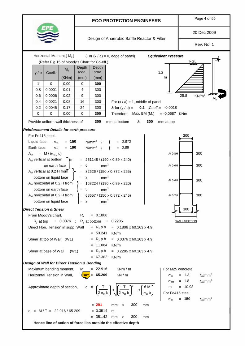
Horizontal Moment ( Mx ) (For (x / a) = 0, edge of panel) Equivalent Pressure(Refer Fig 15 of Moody's Chart for Co-eff.)
m
For (x / a) = 1, middle of panel& for (y / b) = ,Coeff.=Therefore, Max. BM (Mx) = KNm
Provide uniform wall thickness of mm at bottom & mm at top
Reinforcement Details for earth pressureFor Fe415 steel,Liquid face, = N/mm2 ; j =Earth face, = N/mm2 ; j =Ast = M / (σst j d) At 0.8H
FGL
KN/m225.8
300σst
300
0.89190
300
Depth prov.(mm)
y / b Coeff.Mx
Depth reqd.
(KNm) (mm)1 0 0.00 0
0.8 0.0001 4 300300
3000.4 0.0021 0.08 160.6 0.0006
0.01
0 0 0.00 00.2
1.2
0.0045 0.17 24
0.02 9
-0.0018
σst
300
300150 0.872
-0.0687
My
0.2300300
Ast vertical at bottom = 251148 / (190 x 0.89 x 240)on earth face = mm2 At 0.6H
Ast vertical at 0.2 H from = 82626 / (150 x 0.872 x 265)bottom on liquid face = mm2
Ast horizontal at 0.2 H from = 168224 / (190 x 0.89 x 220)bottom on earth face = mm2
Ast horizontal at 0.2 H from = 68657 / (150 x 0.872 x 245) At 0.2H
bottom on liquid face = mm2
Direct Tension & ShearFrom Moody's chart, Rx =
Ry at top = ; Ry at bottom =Direct Hori. Tension in supp. Wall = Rx p b = 0.1806 x 60.163 x 4.9
= KN/mShear at top of Wall (W1) = Ry p b = 0.0376 x 60.163 x 4.9
= KN/mShear at base of Wall (W1) = Ry p b = 0.2285 x 60.163 x 4.9
= KN/mDesign of Wall for Direct Tension & Bending
Maximum bending moment, M = KNm / m For M25 concrete,Horizontal Tension in Wall, T = KN / m = N//mm2
= N//mm2
Approximate depth of section, d = 2 =For Fe415 steel,
= N//mm2
= mm < mme = M / T = 22.916 / 65.209 = m
6 M
0.3514300
σcbt
300
300
300
WALL SECTION
1.8
σct b+
T2 σct b
+
σst
291150
m 10.98
22.91665.209 1.3σct
2300At 0.4H
67.362
5
0.0376
6
2
53.241
11.084
0.22850.1806
2 σct bT
= mm > mmHence line of action of force lies outside the effective depth
300351.42
Page 4 of 55

ECO PROTECTION ENGINEERS
Design of Anaerobic Baffle Reactor & Filter20 Dec 2009
Rev. No. 1
d1 = 300 - 25 - (12 / 2) = mmE = e - d1 + (d / 2) = 351.42 - 269 + (300 / 2) For Fe415 steel,
= mm Liquid face,M1 = T x E = 65.209 x 0.232 = N/mm2
= KNm j =Ast (hori. st.) reqd., = dia of bar = mm
= mm2 / metre heightAst (hori. st.) reqd. on each face = mm2 / metre height on each face
Minimum Reinforcement Details to provideMin. Ast mm thick wall Xn = (0.194/100) x 1000 x 300 = mm2
Min. Ast on each face = mm2
Min. Ast mm thick wall Xn = (0.194/100) x 1000 x 300 = mm2
Min. Ast on each face = mm2
Reinforcement Details to provided
1215.13
291
σst j d1
865
σst+
M1 T
300
582
582291
300
150σst
0.872
269
432.5
232
Vertical ReinforcementAst at bottom on liquid face = mm2
Provide Y mm c/c (Ast prov. = mm2 ) Ast at 0.2H from bottom on liquid face = mm2
Provide Y mm c/c (Ast prov. = mm2 ) Ast at bottom on earth face = mm2
Provide Y mm c/c (Ast prov. = mm2 ) Ast at 0.2H from bottom on earth face = mm2
Provide Y mm c/c (Ast prov. = mm2 )
Horizontal reinforcementAst at 0.2H from bottom on liquid face at middle of wall = mm2
Provide Y mm c/c (Ast prov. = mm2 ) Ast at 0.4H from bottom on liquid face at edge of wall = mm2
Provide Y mm c/c (Ast prov. = mm2 ) Ast at 0.4H from bottom on earth face at middle of wall = mm2
Provide Y mm c/c (Ast prov. = mm2 ) Ast at 0.4H from bottom on earth face at edge of wall = mm2
Provide Y mm c/c (Ast prov. = mm2 )
754
@
327
10 @
291
327291
715754
10 @ 240 327
298
29132710 @ 240
10 @ 240
15012
12 @ 150
291
654
327
240
10 @ 120
10 @ 240
632
291
Page 5 of 55
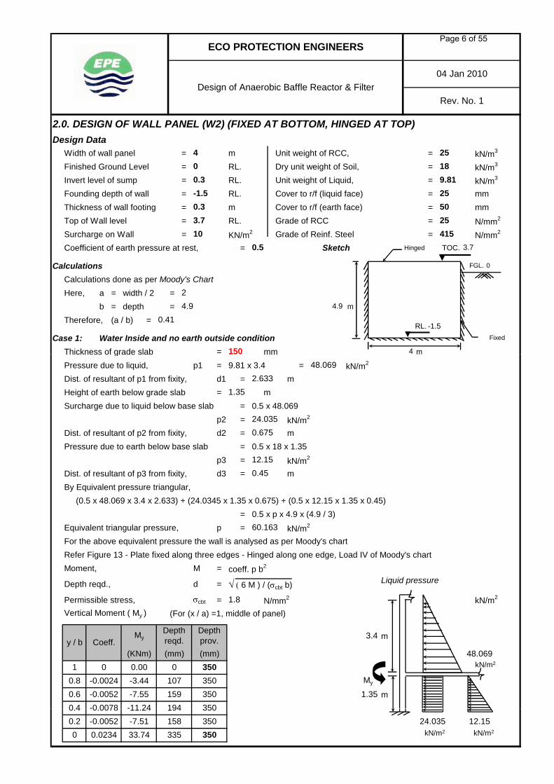
2.0. DESIGN OF WALL PANEL (W2) (FIXED AT BOTTOM, HINGED AT TOP)Design Data
Width of wall panel = m Unit weight of RCC, = kN/m3
Finished Ground Level = RL. Dry unit weight of Soil, = kN/m3
Invert level of sump = RL. Unit weight of Liquid, = kN/m3
Founding depth of wall = RL. Cover to r/f (liquid face) = mmThickness of wall footing = m Cover to r/f (earth face) = mmTop of Wall level = RL. Grade of RCC = N/mm2
Surcharge on Wall = KN/m2 Grade of Reinf. Steel = N/mm2
Coefficient of earth pressure at rest, = Sketch Hinged TOC.
CalculationsCalculations done as per Moody's ChartHere, a = width / 2 =
b = depth = m
Therefore, (a / b) =
Case 1: Water Inside and no earth outside conditionThickness of grade slab = mm m
ECO PROTECTION ENGINEERS
-1.5
00.3
Design of Anaerobic Baffle Reactor & Filter
0.33.7
RL. -1.5
150 4
25
0.41
Fixed
25
10
50
415
24.9
0.5 3.7
FGL. 0
4.9
04 Jan 2010
9.81
Rev. No. 1
4 2518
Thickness of grade slab mm m
Pressure due to liquid, p1 = 9.81 x 3.4 = kN/m2
Dist. of resultant of p1 from fixity, d1 = mHeight of earth below grade slab = mSurcharge due to liquid below base slab = 0.5 x 48.069
p2 = kN/m2
Dist. of resultant of p2 from fixity, d2 = mPressure due to earth below base slab = 0.5 x 18 x 1.35
p3 = kN/m2
Dist. of resultant of p3 from fixity, d3 = mBy Equivalent pressure triangular,
(0.5 x 48.069 x 3.4 x 2.633) + (24.0345 x 1.35 x 0.675) + (0.5 x 12.15 x 1.35 x 0.45)= 0.5 x p x 4.9 x (4.9 / 3)
Equivalent triangular pressure, p = kN/m2
For the above equivalent pressure the wall is analysed as per Moody's chartRefer Figure 13 - Plate fixed along three edges - Hinged along one edge, Load IV of Moody's chartMoment, M = coeff. p b2
Depth reqd., d = √ ( 6 M ) / (σcbt b) Liquid pressure
Permissible stress, = N/mm2
Vertical Moment ( My ) (For (x / a) =1, middle of panel)
m
m
350
2.633
0.67524.035
150
1.35
0.45
60.163
My
48.069
kN/m2
159
0.00-3.44
(KNm)
σcbt
(mm)
0.6
0-0.0024-0.0052
10.8
y / b
12.15
My
48.069
1.8
Coeff.
1.35
Depth reqd.(mm)
Depth prov.
-11 24 194-7.55
107
3.4
350
-0 0078
0
0 4350350
kN/m2
24.035 12.1511.24-7.51 158
194
0 0.0234 33.74 335 3500.2
0.00780.4 350-0.0052 350
kN/m2 kN/m2
Page 6 of 55

ECO PROTECTION ENGINEERS
Design of Anaerobic Baffle Reactor & Filter04 Jan 2010
Rev. No. 1
Horizontal Moment ( Mx ) (For (x / a) = 0, edge of panel)
For (x / a) = 1, middle of panel& for (y / b) = ,Coeff.=Therefore, Max. BM (Mx) = KNm
Reinforcement Details for liquid pressureAst = M / (σst j d) For Fe415 steel,Ast vertical at bottom = 33743838 / (150 x 0.872 x 315) Liquid face,
on liquid face = mm2 = N/mm2
Ast vertical at 0.2 H from = 7511471 / (190 x 0.89 x 290) j =bottom on earth face = mm2 Earth face,
A h i t l t 0 4 H f 32409108 / (150 0 872 295) 2
-15.006
350
1500.872
190
3500 0 0.00 00.2 0.0149 21.51 268 0.4 -0.01043500.4 0.0224 32.41 329 3500.6 0.0191 27.59 303 3500.8 0.0104 15.09 224 3501 0 0.00 0
(mm)
Depth prov.y / b Coeff.
MxDepth reqd.
(KNm) (mm)
153
819 σst
Ast horizontal at 0.4 H from = 32409108 / (150 x 0.872 x 295) = N/mm2
bottom on liquid face = mm2 j =Ast horizontal at 0.4 H from = 15005608 / (190 x 0.89 x 270)
bottom on earth face = mm2
Case 2: Earth outside & no water inside conditionHeight of earth = ( 0 ) - ( -1.5 ) - 0.3 = mPressure due to earth = 0.5 x 18 x 1.2 = KN/m2
Pressure due to surcharge = 0.5 x 10 = KN/m2
By Equivalent pressure triangular,p x 1.2^2 / 6 = ((10.8 x 1.2^2 / 6) + (5 x 1.2^2 / 2))
Therefore, p = KN/m2
Vertical Moment ( My ) (For (x / a) =1, middle of panel) Pressure from outside
(Refer Fig 15 of Moody's Chart for Co-eff.)
10.8
GWT
350
Depth prov.
4350
5
m
1.2
190
25.8
5350
(mm)0
10.8
y / b Coeff.My
Depth reqd.
(KNm) (mm)1
0.4
0.000 0.000.8 0.000 0.010.6 0.000 0.00
My
0.008
-0.030.2 -0.003 -0.11
0.310
1.2
-0.001
5
+
FGL
840
19 350
350
32
329
0.89
350
σst
9
Page 7 of 55
ECO PROTECTION ENGINEERS
Design of Anaerobic Baffle Reactor & Filter04 Jan 2010
Rev. No. 1
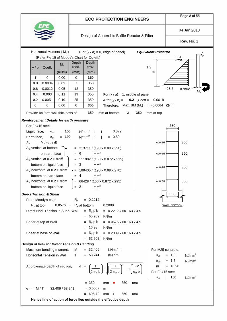
Horizontal Moment ( Mx ) (For (x / a) = 0, edge of panel) Equivalent Pressure(Refer Fig 15 of Moody's Chart for Co-eff.)
m
For (x / a) = 1, middle of panel& for (y / b) = ,Coeff.=Therefore, Max. BM (Mx) = KNm
Provide uniform wall thickness of mm at bottom & mm at top
Reinforcement Details for earth pressureFor Fe415 steel,Liquid face, = N/mm2 ; j =Earth face, = N/mm2 ; j =Ast = M / (σst j d) At 0.8H
FGL
KN/m225.8
350
350
350
0.89σst
(KNm) (mm)
0.0004
Depth prov.
1 0 0.00 00.02 7
350
0.4 0.003 0.11 190.6 0.0012
350
y / b Coeff.Mx
Depth reqd. 1.2
0.0051 0.19 25
0.05 12
-0.06640.2 -0.0018
00.2
(mm)
0 0 0.00
0.8
σst
350
350150 0.872
350
My
190
350
350
Ast vertical at bottom = 313711 / (190 x 0.89 x 290)on earth face = mm2 At 0.6H
Ast vertical at 0.2 H from = 111902 / (150 x 0.872 x 315)bottom on liquid face = mm2
Ast horizontal at 0.2 H from = 188435 / (190 x 0.89 x 270)bottom on earth face = mm2
Ast horizontal at 0.2 H from = 66428 / (150 x 0.872 x 295) At 0.2H
bottom on liquid face = mm2
Direct Tension & ShearFrom Moody's chart, Rx =
Ry at top = ; Ry at bottom =Direct Hori. Tension in Supp. Wall = Rx p b = 0.2212 x 60.163 x 4.9
= KN/mShear at top of Wall = Ry p b = 0.0576 x 60.163 x 4.9
= KN/mShear at base of Wall = Ry p b = 0.2809 x 60.163 x 4.9
= KN/mDesign of Wall for Direct Tension & Bending
Maximum bending moment, M = KNm / m For M25 concrete,Horizontal Tension in Wall, T = KN / m = N//mm2
= N//mm2
Approximate depth of section, d = 2 =For Fe415 steel,
= N//mm2
= mm = mme = M / T = 32.409 / 53.241 = m
6 M
350 3500.6087
1.8
WALL SECTION
350
350
σcbt
350
1.3
2 σct bT
σct b+
T2 σct b
+
σst 150
m 10.98
32.40953.241
350At 0.4H
σct
6
2
65.209
3
0.28090.2212
16.98
82.809
4
0.0576
= mm > mmHence line of action of force lies outside the effective depth
350608.72
Page 8 of 55
ECO PROTECTION ENGINEERS
Design of Anaerobic Baffle Reactor & Filter04 Jan 2010
Rev. No. 1
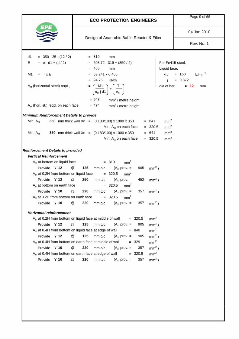
d1 = 350 - 25 - (12 / 2) = mmE = e - d1 + (d / 2) = 608.72 - 319 + (350 / 2) For Fe415 steel,
= mm Liquid face,M1 = T x E = 53.241 x 0.465 = N/mm2
= KNm j =Ast (horizontal steel) reqd., = dia of bar = mm
= mm2 / metre heightAst (hori. st.) reqd. on each face = mm2 / metre height
Minimum Reinforcement Details to provideMin. Ast mm thick wall Xn = (0.183/100) x 1000 x 350 = mm2
Min. Ast on each face = mm2
Min. Ast mm thick wall Xn = (0.183/100) x 1000 x 350 = mm2
Min. Ast on each face = mm2
Reinforcement Details to provided
1224.76
320.5
M1 T
350
641
641320.5
350
σst j d1
474948
σst+
150465
0.872σst
319
Vertical ReinforcementAst at bottom on liquid face = mm2
Provide Y mm c/c (Ast prov. = mm2 ) Ast at 0.2H from bottom on liquid face = mm2
Provide Y mm c/c (Ast prov. = mm2 ) Ast at bottom on earth face = mm2
Provide Y mm c/c (Ast prov. = mm2 ) Ast at 0.2H from bottom on earth face = mm2
Provide Y mm c/c (Ast prov. = mm2 )
Horizontal reinforcementAst at 0.2H from bottom on liquid face at middle of wall = mm2
Provide Y mm c/c (Ast prov. = mm2 ) Ast at 0.4H from bottom on liquid face at edge of wall = mm2
Provide Y mm c/c (Ast prov. = mm2 ) Ast at 0.4H from bottom on earth face at middle of wall = mm2
Provide Y mm c/c (Ast prov. = mm2 ) Ast at 0.4H from bottom on earth face at edge of wall = mm2
Provide Y mm c/c (Ast prov. = mm2 )
12 @ 125 905
@320.5
357
12
357
840905
10 @ 220 357
329
320.535710 @ 220
10 @ 220
125
10 @320.5
220
12 @ 125
12 @ 250
819
320.5
320.5
905
452
Page 9 of 55

3.0. DESIGN OF WALL PANEL (W3) (FIXED AT BOTTOM, HINGED AT TOP)Design Data
Width of wall panel = m Unit weight of RCC, = kN/m3
Finished Ground Level = RL. Dry unit weight of Soil, = kN/m3
Invert level of sump = RL. Unit weight of Liquid, = kN/m3
Founding depth of wall = RL. Cover to r/f (liquid face) = mmThickness of wall footing = m Cover to r/f (earth face) = mmTop of Wall level = RL. Grade of RCC = N/mm2
Surcharge on Wall = KN/m2 Grade of Reinf. Steel = N/mm2
Coefficient of earth pressure at rest, = Sketch Hinged TOC.
CalculationsCalculations done as per Moody's ChartHere, a = width / 2 =
b = depth = m
Therefore, (a / b) =
Case 1: Water Inside and no earth outside conditionThickness of grade slab = mm m
20 Dec 2009
9.81
Rev. No. 1
4.3 2518
2.154.9
25
-1.5
0.5 3.7
FGL.
4.9
415
25
10
500.33.7
0
0.44
4.3
Fixed
RL.
150
ECO PROTECTION ENGINEERS
-1.5
00.3
Design of Anaerobic Baffle Reactor & Filter
Thickness of grade slab mm m
Pressure due to liquid, p1 = 9.81 x 3.4 = kN/m2
Dist. of resultant of p1 from fixity, d1 = mHeight of earth below grade slab = mSurcharge due to liquid below base slab = 0.5 x 48.069
p2 = kN/m2
Dist. of resultant of p2 from fixity, d2 = mPressure due to earth below base slab = 0.5 x 18 x 1.35
p3 = kN/m2
Dist. of resultant of p3 from fixity, d3 = mBy Equivalent pressure triangular,
(0.5 x 48.069 x 3.4 x 2.633) + (24.0345 x 1.35 x 0.675) + (0.5 x 12.15 x 1.35 x 0.45)= 0.5 x p x 4.9 x (4.9 / 3)
Equivalent triangular pressure, p = kN/m2
For the above equivalent pressure the wall is analysed as per Moody's chartRefer Figure 13 - Plate fixed along three edges - Hinged along one edge, Load IV of Moody's chartMoment, M = coeff. p b2
Depth reqd., d = √ ( 6 M ) / (σcbt b) Liquid pressure
Permissible stress, = N/mm2
Vertical Moment ( My ) (For (x / a) =1, middle of panel)
m
m-9.32-0.00910.4
3750.6-13.08 375209
121176
My375
My
48.069
1.8
Coeff.
1.35
Depth reqd.(mm)
Depth prov.
10.8
0.00-4.41
y / b
0 375(KNm)
0-0.0031-0.0065
24.035
12.15
3.4
σcbt
(mm)
2.633
60.163
48.069
kN/m2
1.35
4.3
0.675
0.45
150
kN/m2
-7.51 158375
24.035 12.150.2-0.00910.4-0.0052 375
-13.08 375209
0 0.0262 37.90 355
kN/m2
kN/m2 kN/m2
Page 10 of 55
20 Dec 2009
Rev. No. 1
ECO PROTECTION ENGINEERS
Design of Anaerobic Baffle Reactor & Filter
Horizontal Moment ( Mx ) (For (x / a) = 0, edge of panel)
For (x / a) = 1, middle of panel& for (y / b) = ,Coeff.=Therefore, Max. BM (Mx) = KNm
Reinforcement Details for liquid pressureAst = M / (σst j d) For Fe415 steel,Ast vertical at bottom = 37904038 / (150 x 0.872 x 340) Liquid face,
on liquid face = mm2 = N/mm2
Ast vertical at 0.4H from = 13081515 / (190 x 0.89 x 315) j =bottom on earth face = mm2 Earth face,
A horizontal at 0 4H from 34558544 / (150 0 872 320) N/ 2
246
852
190
(mm) (mm)y / b Coeff.
MxDepth reqd.
Depth prov.
(KNm)1 0 0.00 0 375
0.8 0.0116 16.75 236 3750.6 0.0209 30.19 317 375
3750.4 0.0239 34.56 339 375
150
0.2 0.0152 22.00 271 0.4 -0.01090 0 0.00 0
0.872
375 -15.734
σst
Ast horizontal at 0.4H from = 34558544 / (150 x 0.872 x 320) = N/mm2
bottom on liquid face = mm2 j =Ast horizontal at 0.4 H from = 15733642 / (190 x 0.89 x 295)
bottom on earth face = mm2
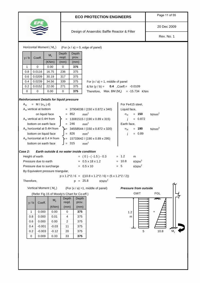
Case 2: Earth outside & no water inside conditionHeight of earth = ( 0 ) - ( -1.5 ) - 0.3 = mPressure due to earth = 0.5 x 18 x 1.2 = KN/m2
Pressure due to surcharge = 0.5 x 10 = KN/m2
By Equivalent pressure triangular,p x 1.2^2 / 6 = ((10.8 x 1.2^2 / 6) + (5 x 1.2^2 / 2))
Therefore, p = KN/m2
Vertical Moment ( My ) (For (x / a) =1, middle of panel) Pressure from outside
(Refer Fig 15 of Moody's Chart for Co-eff.)
826
Depth prov.
375
2
190
5
+
FGL
1.2
-0.001
0.009375
0.33 335
3750.2 -0.003 -0.12 200
0.4
0.000 0.000.8
-0.03
375
11
0.000 4375
0.89
0.010.6 0.000 0.00
1
y / b Coeff.My
Depth reqd.
(KNm) (mm)
315
σst
(mm)0
m375
My10.8
GWT
25.8
1.210.8
Page 11 of 55

20 Dec 2009
Rev. No. 1
ECO PROTECTION ENGINEERS
Design of Anaerobic Baffle Reactor & Filter
Horizontal Moment ( Mx ) (For (x / a) = 0, edge of panel) Equivalent Pressure(Refer Fig 15 of Moody's Chart for Co-eff.)
m
For (x / a) = 1, middle of panel& for (y / b) = ,Coeff.=Therefore, Max. BM (Mx) = KNm
Provide uniform wall thickness of mm at bottom & mm at top
Reinforcement Details for earth pressureFor Fe415 steel,Liquid face, = N/mm2 ; j =Earth face, = N/mm2 ; j =Ast = M / (σst j d) At 0.8H
My
-0.0629-0.0017
0.05 13
σst
375
375150 0.872
0.19 25
375
0.23750 0 0.00 0
0.2 0.0053750.4 0.0032 0.12 20
0.6 0.00143753751 0 0.00 0
0.02 80.8 0.0005
(mm)y / b Coeff.
MxDepth reqd.
(KNm) (mm)1.2
190σst 0.89
25.8
375
KN/m2
Depth prov.
375
FGL
375
Ast vertical at bottom = 334219 / (190 x 0.89 x 315)on earth face = mm2 At 0.6H
Ast vertical at 0.2 H from = 115468 / (150 x 0.872 x 340)bottom on liquid face = mm2
Ast horizontal at 0.2 H from = 187543 / (190 x 0.89 x 295)bottom on earth face = mm2
Ast horizontal at 0.2 H from = 62861 / (150 x 0.872 x 320) At 0.2H
bottom on liquid face = mm2
Direct Tension & ShearFrom Moody's chart, Rx =
Ry at top = ; Ry at bottom =Direct Hori. Tension in supp. Wall = Rx p b = 0.2292 x 60.163 x 4.9
= KN/mShear at top of Wall (W1) = Ry p b = 0.064 x 60.163 x 4.9
= KN/mShear at base of Wall (W1) = Ry p b = 0.2948 x 60.163 x 4.9
= KN/mDesign of Wall for Direct Tension & Bending
Maximum bending moment, M = KNm / m For M25 concrete,Horizontal Tension in Wall, T = KN / m = N//mm2
= N//mm2
Approximate depth of section, d = 2 =For Fe415 steel,
= N//mm2
= mm < mme = M / T = 34.559 / 53.241 = m
2 σct bT
18.867
86.907
4
0.064
6
2
67.568
3375At 0.4H
1.3σct
0.29480.2292
150
m 10.98
34.55953.241
1.8
σst
375
WALL SECTION
375
375
σcbt
T2 σct b
+σct b
+
3750.6491
6 M
361
= mm > mmHence line of action of force lies outside the effective depth
375649.11
Page 12 of 55
20 Dec 2009
Rev. No. 1
ECO PROTECTION ENGINEERS
Design of Anaerobic Baffle Reactor & Filter
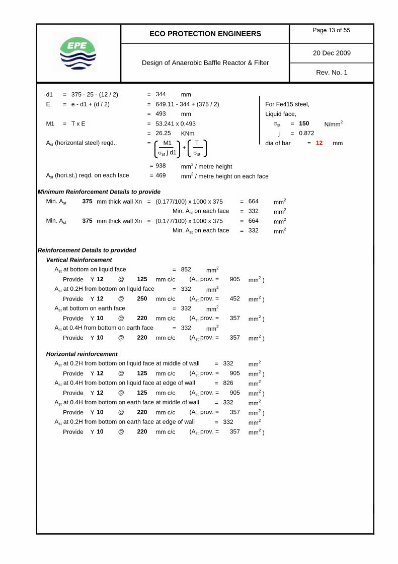
d1 = 375 - 25 - (12 / 2) = mmE = e - d1 + (d / 2) = 649.11 - 344 + (375 / 2) For Fe415 steel,
= mm Liquid face,M1 = T x E = 53.241 x 0.493 = N/mm2
= KNm j =Ast (horizontal steel) reqd., = dia of bar = mm
= mm2 / metre heightAst (hori.st.) reqd. on each face = mm2 / metre height on each face
Minimum Reinforcement Details to provideMin. Ast mm thick wall Xn = (0.177/100) x 1000 x 375 = mm2
Min. Ast on each face = mm2
Min. Ast mm thick wall Xn = (0.177/100) x 1000 x 375 = mm2
Min. Ast on each face = mm2
Reinforcement Details to provided
469
493150σst
σst
0.872M1 T
344
375
σst j d1
375
664
664332
938
332
26.2512
+
Vertical ReinforcementAst at bottom on liquid face = mm2
Provide Y mm c/c (Ast prov. = mm2 ) Ast at 0.2H from bottom on liquid face = mm2
Provide Y mm c/c (Ast prov. = mm2 ) Ast at bottom on earth face = mm2
Provide Y mm c/c (Ast prov. = mm2 ) Ast at 0.4H from bottom on earth face = mm2
Provide Y mm c/c (Ast prov. = mm2 )
Horizontal reinforcementAst at 0.2H from bottom on liquid face at middle of wall = mm2
Provide Y mm c/c (Ast prov. = mm2 ) Ast at 0.4H from bottom on liquid face at edge of wall = mm2
Provide Y mm c/c (Ast prov. = mm2 ) Ast at 0.4H from bottom on earth face at middle of wall = mm2
Provide Y mm c/c (Ast prov. = mm2 ) Ast at 0.2H from bottom on earth face at edge of wall = mm2
Provide Y mm c/c (Ast prov. = mm2 )
852
332
332
905
452
125
12 @ 250
10 @
10 @ 220
10 @ 220
125
12 @ 125826
905
10 @ 220 357
332
332
905
357
12
357
220
12 @
@332
357332
Page 13 of 55

4.0. DESIGN OF WALL PANEL (W4)Design Data
Width of wall panel = m Unit weight of RCC, = KN/m3
Ground Level = RL. Dry unit weight of Soil, = KN/m3
Invert level of sump = RL. Unit weight of Liquid, = KN/m3
Top of Wall level = RL. Grade of RCC = N/mm2
Founding Depth = RL. Grade of Reinf. Steel = N/mm2
Surcharge on Wall = KN/m2
Cover to r/f (liquid face) = mm Hinged TOC.Cover to r/f (earth face) = mmCoefficient of active earth pressure, =
Calculations m
Calculations done as per Moody's ChartHere, a = width / 2 = IL.
b = depth =Therefore, (a / b) = m
Case 1: (Water inside and no earth outside)Height of water = m
0
3 4
25189.81
ECO PROTECTION ENGINEERS
Design of Anaaerobic Baffle Reactor & Filter
25415
0.3
20 Dec 2009
Rev. No. 1
31.8
3.7
2540
10
0.33
3.7
3.5
1.53.5
0.43
Fixed
3
0.3
Height of water = mPressure due to water = (9.81x3.4) = KN/m2
Refer Figure 13 - Plate fixed along three edges - Hinged along one edge, Load IV of Moody's chart
Moment, M = coeff. p b2
Depth reqd., d = √ ( 6 M ) / (σcbt b)
Permissible stress, = 2 N/mm2
Vertical Moment ( My ) (For (x / a) =1, middle of panel)
3
KN/m2
Horizontal Moment ( Mx ) (For (x / a) = 0, edge of panel)
For (x / a) = 1, middle of panel& for (y / b) = ,Coeff.=Therefore, Max. BM (Mx) = KNm
33.35
225
(mm)
1668.29
3.5
My225
-4.3817
-2.47225
225
3.4
Depth reqd.
0.40.2
-0.00863
-0.00520
-3.530.6
1
Coeff.My
(mm)
σcbt
00.8
0.00000
-0.00283 -1.16
(KNm)0.00
y / b(mm)
Depth prov.
y / b Coeff.Mx
Depth reqd.
(KNm)
62
-2.12
91108
-0.00604 22533.354225
84 2250 0.02528 10.33 186
1 0.00000 0.00 0225
0.4 0.02343 9.57 179
0.8 0.01121 4.58 1240.6 0.02030
6.18 143 0.4 -0.01070 0.00000 0.00 0 225
225225225
(mm)
Depth prov.
0.2 0.01512
Provide depth = Provide mm225120.85365
Page 14 of 55

ECO PROTECTION ENGINEERS
Design of Anaaerobic Baffle Reactor & Filter20 Dec 2009
Rev. No. 1
Reinforcement Details for liquid pressureAst = M / (σst j d) For Fe415 steel,Ast vertical at bottom = 10329067 / (150 x 0.872 x 196) Liquid face,
on liquid face = mm2 = N/mm2
Ast vertical at 0.2 H from = 2124650 / (190 x 0.89 x 181) j =bottom on earth face = mm2 Earth face,
Ast horizontal at 0.4H from = 9572365 / (150 x 0.872 x 188) = N/mm2
bottom on liquid face = mm2 j =Ast horizontal at 0.4H from = 4381682 / (190 x 0.89 x 173)
bottom on earth face = mm2
Case 2: (Earth outside & Tank empty condition)Height of earth = ( 1.8 ) - ( 0 ) = mPressure due to earth = 0.33 x 18 x 1.8 = KN/m2
Pressure due to surcharge = 0.33 x 10 = KN/m2
Equivalent pressure triangular,1 8^2 / 6 ((10 692 1 8^2 / 6) + (3 3 1 8^2 / 2))
0.872
150
389σst
403
3.3
0.89
1.810.692
69190
σst 150
p x 1.8^2 / 6 = ((10.692 x 1.8^2 / 6) + (3.3 x 1.8^2 / 2))Therefore, p = KN/m2
Vertical Moment ( My ) (For (x / a) =1, middle of panel) Pressure from outside
Equivalent Pressure
Horizontal Moment ( Mx ) (For (x / a) = 0, edge of panel)
m
For (x / a) = 1, middle of panel& for (y / b) = ,Coeff.=Therefore, Max. BM (Mx) = KNmProvide depth = mm
75
72225225
0.02343
(KNm)
58
1.8
225
My225
0
Depth reqd.
225Provide of thicknesswall
0 0.00000 0.000.2 0.01512 1.01
225
0.8 0.01121 0.75 500.60.4 1.56
0.02030 1.35 67
0.00000 0.00(mm)
0
Depth prov.
0
y / b
1
10.692225
Coeff.Mx
3.3 My
-0.19
-0.58
25
84
m
225
0.6 -0.00604
0.02528 1.69
0.40.2 -0.03141 -2.10
-0.00283
225-0.40 37 225
-0.00863
1 0.00000
44
0.8
(mm)0.00 0 225 +
FGL
y / b Coeff.My
Depth reqd.
(KNm)
1.8
20.592
(mm)
FGL
0.4
48.836
-0.0107
20.592 KN/m2
Provide -0.7155
mm throughout
225
Depth prov.
(mm)225
225
Page 15 of 55

ECO PROTECTION ENGINEERS
Design of Anaaerobic Baffle Reactor & Filter20 Dec 2009
Rev. No. 1
Reinforcement Details for earth pressureFor Fe415 steel,Liquid face, = N/mm2 ; j =Earth face, = N/mm2 ; j =Ast = M / (σst j d) At 0.8H
Ast vertical at bottom = 1686633 / (190 x 0.89 x 181)on earth face = mm2 At 0.6H
Ast vertical at 0.2 H from = 2095481 / (150 x 0.872 x 196)bottom on liquid face = mm2
Ast horizontal at 0.4 H from = 1563071 / (190 x 0.89 x 173)bottom on earth face = mm2
Ast horizontal at 0.4 H from = 715485 / (150 x 0.872 x 188) At 0.2H
bottom on liquid face = mm2
Direct Tension & ShearFrom Moody's chart, Rx =
Ry at bottom = Ry at top =Direct Hori. Tension in Wall = Rx p b = 0.2265 x 20.592 x 3.5
55
σst
σst 0.890.872
190150
0.2901
225
At 0.4H82
225
225
225
WALL SECTION0.0619
29225
0.2265
53
Direct Hori. Tension in Wall = Rx p b = 0.2265 x 20.592 x 3.5= KN/m
Shear at base of Wall = Ry p b = 0.2901 x 20.592 x 3.5= KN/m
Shear at top of Wall = Ry p b = 0.0619 x 20.592 x 3.5= KN/m
Design of Wall for Direct Tension & BendingMaximum bending moment, M = KNm / m For M25 concrete,Horizontal Tension in Wall, T = KN / m = N//mm2
= N//mm2
Approximate depth of section, d = 2 =For Fe415 steel,
= N//mm2
= mm < mme = M / T = 9.572 / 21.122 = m
= mmHence line of action of force lies outside the effective depth
d1 = 225 - 25 - (10 / 2) = mmE = e - d1 + (d / 2) = 453.18 - 195 + (225 / 2) For Fe415 steel,
= mm Liquid face,M1 = T x E = 21.122 x 0.371 = N/mm2
= KNm j =Ast (horizontal steel) reqd., =
= mm2 / metre height
Reinforcement Details to provide
9.572
+σct b
150
m
371
2 σct bT
187
20.908
1500.872
0.4532
T
1.3
453.18
21.122
σst+
M1 T
+
σcbt
σct
1.8
σst j d1
σst
10.98
16.324
225
195
7.84
448
4.461
σst
6 M2 σct b
pMin. Ast for mm thick wall Xn = (0.211/100) x 1000 x 225 = mm2
Min. Ast on each face = mm2237.5225 475
Page 16 of 55

ECO PROTECTION ENGINEERS
Design of Anaaerobic Baffle Reactor & Filter20 Dec 2009
Rev. No. 1
Reinforcement Details to provideVertical Reinforcement
Ast at bottom on liquid face = mm2
Provide Y mm c/c (Ast prov. = mm2 ) Ast at 0.2H from bottom on liquid face = mm2
Provide Y mm c/c (Ast prov. = mm2 ) Ast at bottom on earth face = mm2
Provide Y mm c/c (Ast prov. = mm2 ) Ast at 0.2H from bottom on earth face = mm2
Provide Y mm c/c (Ast prov. = mm2 )
Horizontal reinforcementAst at 1 H from bottom on liquid face at middle of wall = mm2
Provide Y mm c/c (Ast prov. = mm2 ) Ast at 0.2H from bottom on liquid face at edge of wall = mm2
Y (Ast prov. = mm2 ) Ast at 0.4H from bottom on earth face at middle of wall = mm2
P id Y / (A prov = 2 )
10 @ 170448462@10
8 @
10 @ 170
8 @ 200
8 @
8 @ 200
200
237.5
403
237.5100
462
237.5251
462
237.5
237.5
170
503
251
251
Provide Y mm c/c (Ast prov. = mm2 ) Ast at 0.4H from bottom on earth face at edge of wall = mm2
Y (Ast prov. = mm2 ) 10 @ 170
10 @ 170448462
462
Page 17 of 55

5.0. DESIGN OF WALL PANEL (W5)Design Data
Width of wall panel = m Unit weight of RCC, = KN/m3
Ground Level = RL. Dry unit weight of Soil, = KN/m3
Invert level of sump = RL. Unit weight of Liquid, = KN/m3
Top of Wall level = RL. Grade of RCC = N/mm2
Founding Depth = RL. Grade of Reinf. Steel = N/mm2
Surcharge on Wall = KN/m2
Cover to r/f (liquid face) = mm Hinged TOC.Cover to r/f (earth face) = mmCoefficient of active earth pressure, =
Calculations m
Calculations done as per Moody's ChartHere, a = width / 2 = IL.
b = depth =Therefore, (a / b) = m
Case 1: (Water inside and no earth outside)Height of water = m
Fixed
4
0.3
0.57
3.5
23.5
3.7
40
10
0.33
25415
0.3
20 Dec 2009
Rev. No. 1
41.8
3.7
25
25189.81
ECO PROTECTION ENGINEERS
Design of Anaaerobic Baffle Reactor & Filter
3 4
0
Height of water = mPressure due to water = (9.81x3.4) = KN/m2
Refer Figure 13 - Plate fixed along three edges - Hinged along one edge, Load IV of Moody's chart
Moment, M = coeff. p b2
Depth reqd., d = √ ( 6 M ) / (σcbt b)
Permissible stress, = N/mm2
Vertical Moment ( My ) (For (x / a) =1, middle of panel)
3
KN/m2
Horizontal Moment ( Mx ) (For (x / a) = 0, edge of panel)
For (x / a) = 1, middle of panel& for (y / b) = ,Coeff.=Therefore, Max. BM (Mx) = KNm
250
250250250
2500 0.00000 0.00 00.2 0.01579 6.45 147 0.4 -0.0116
10.65 1880.4 0.02782 11.37 195
0.8 0.01508 6.16 1430.6 0.02607
1 0.00000 0.00 0(mm)
Depth prov.
77 2500 0.03718 15.19 225
25033.354250
y / b Coeff.Mx
Depth reqd.
(KNm)
93
-1.77
127138
-0.01190
(mm)
Depth prov.
0.80.00000
-0.00633 -2.59
(KNm)0.00
y / b
1
Coeff.My
(mm)
σcbt
0
0.40.2
-0.01390
-0.00433
-5.680.6 -4.86
250
250
3.4
Depth reqd.
33.35
3.5
My250
-4.7478
250
(mm)
1.8
Provide depth = Provide mm125.8011 250
Page 18 of 55

20 Dec 2009
Rev. No. 1
ECO PROTECTION ENGINEERS
Design of Anaaerobic Baffle Reactor & Filter
Reinforcement Details for liquid pressureAst = M / (σst j d) For Fe415 steel,Ast vertical at bottom = 15191246 / (150 x 0.872 x 221) Liquid face,
on liquid face = mm2 = N/mm2
Ast vertical at 0.2 H from = 1769997 / (190 x 0.89 x 206) j =bottom on earth face = mm2 Earth face,
Ast horizontal at 0.4H from = 11368511 / (150 x 0.872 x 213) = N/mm2
bottom on liquid face = mm2 j =Ast horizontal at 0.4H from = 4747775 / (190 x 0.89 x 198)
bottom on earth face = mm2
Case 2: (Earth outside & Tank empty condition)Height of earth = ( 1.8 ) - ( 0 ) = mPressure due to earth = 0.33 x 18 x 1.8 = KN/m2
Pressure due to surcharge = 0.33 x 10 = KN/m2
Equivalent pressure triangular,1 8^2 / 6 ((10 692 1 8^2 / 6) + (3 3 1 8^2 / 2))
51
3.3
0.89
1.810.692
σst
526
190
σst 1500.872
142
408
p x 1.8^2 / 6 = ((10.692 x 1.8^2 / 6) + (3.3 x 1.8^2 / 2))Therefore, p = KN/m2
Vertical Moment ( My ) (For (x / a) =1, middle of panel) Pressure from outside
Equivalent Pressure
Horizontal Moment ( Mx ) (For (x / a) = 0, edge of panel)
m
For (x / a) = 1, middle of panel& for (y / b) = ,Coeff.=Therefore, Max. BM (Mx) = KNmProvide depth = mm50.835 Provide
(mm)250
3.3
20.592
0.4
250
Depth prov.
250250 -0.0116
My
KN/m2
38
31
m
250FGL
250
1.8
20.592
(mm)+
FGL
y / b Coeff.My
Depth reqd.
(KNm)1 0.00000
56
0.8
(mm)0.00 0 250
-0.00633
250-0.79 51 250
-0.01390
-0.42
-0.930.6 -0.01190
0.03718 2.48
0.40.2 -0.00433 -0.290
y / b
1
10.692250
Coeff.Mx
0.00000 0.00(KNm)
Depth reqd.(mm)
0
Depth prov.
0.8 0.01508 1.01 580.6 0.02607 1.74 76
0.01579 1.05
250
My1.860.02782 79
Provide of thicknesswall
0.4
0 0.00000 0.000.2
0 250 -0.7753
mm throughout250
250
91
59
1.8
Page 19 of 55
20 Dec 2009
Rev. No. 1
ECO PROTECTION ENGINEERS
Design of Anaaerobic Baffle Reactor & Filter
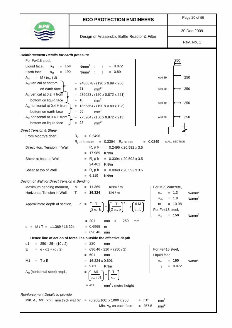
Reinforcement Details for earth pressureFor Fe415 steel,Liquid face, = N/mm2 ; j =Earth face, = N/mm2 ; j =Ast = M / (σst j d) At 0.8H
Ast vertical at bottom = 2480578 / (190 x 0.89 x 206)on earth face = mm2 At 0.6H
Ast vertical at 0.2 H from = 289023 / (150 x 0.872 x 221)bottom on liquid face = mm2
Ast horizontal at 0.4 H from = 1856364 / (190 x 0.89 x 198)bottom on earth face = mm2
Ast horizontal at 0.4 H from = 775264 / (150 x 0.872 x 213) At 0.2H
bottom on liquid face = mm2
Direct Tension & ShearFrom Moody's chart, Rx =
Ry at bottom = Ry at top =Direct Hori. Tension in Wall = Rx p b = 0.2496 x 20.592 x 3.5
55
250
250
250
WALL SECTION
28
0.2496
250
0.3394
250
0.0849
At 0.4H
σst 0.890.872
190150
10
71
σst
Direct Hori. Tension in Wall = Rx p b = 0.2496 x 20.592 x 3.5= KN/m
Shear at base of Wall = Ry p b = 0.3394 x 20.592 x 3.5= KN/m
Shear at top of Wall = Ry p b = 0.0849 x 20.592 x 3.5= KN/m
Design of Wall for Direct Tension & BendingMaximum bending moment, M = KNm / m For M25 concrete,Horizontal Tension in Wall, T = KN / m = N//mm2
= N//mm2
Approximate depth of section, d = 2 =For Fe415 steel,
= N//mm2
= mm < mme = M / T = 11.369 / 16.324 = m
= mmHence line of action of force lies outside the effective depth
d1 = 250 - 25 - (10 / 2) = mmE = e - d1 + (d / 2) = 696.46 - 220 + (250 / 2) For Fe415 steel,
= mm Liquid face,M1 = T x E = 16.324 x 0.601 = N/mm2
= KNm j =Ast (horizontal steel) reqd., =
= mm2 / metre height
Reinforcement Details to provide
σst
6 M2 σct b
9.81
10.98+
σcbt
17.989
σst j d1
450
σst+
M1 T
1500.872
0.6965
T
1.3
696.46
16.324
σst
220
601
2 σct bT
201
m
24.461
6.119
σct
σct b
1.8
11.369
+
250150
pMin. Ast for mm thick wall Xn = (0.206/100) x 1000 x 250 = mm2
Min. Ast on each face = mm2
250257.5515
Page 20 of 55

20 Dec 2009
Rev. No. 1
ECO PROTECTION ENGINEERS
Design of Anaaerobic Baffle Reactor & Filter
Reinforcement Details to provideVertical Reinforcement
Ast at bottom on liquid face = mm2
Provide Y mm c/c (Ast prov. = mm2 ) Ast at 0.2H from bottom on liquid face = mm2
Provide Y mm c/c (Ast prov. = mm2 ) Ast at bottom on earth face = mm2
Provide Y mm c/c (Ast prov. = mm2 ) Ast at 0.2H from bottom on earth face = mm2
Provide Y mm c/c (Ast prov. = mm2 )
Horizontal reinforcementAst at 1 H from bottom on liquid face at middle of wall = mm2
Provide Y mm c/c (Ast prov. = mm2 ) Ast at 0.2H from bottom on liquid face at edge of wall = mm2
Y mm c/c (Ast prov. = mm2 ) Ast at 0.4H from bottom on earth face at middle of wall = mm2
P id Y / (A prov = 2 )
257.5
628
314
524
257.5280
524
257.5
257.5
280
257.5
@ 250
10 @ 280
10 @
10
10 @ 150
280
150
526
10
125
10 @ 150450524@
10 @
Provide Y mm c/c (Ast prov. = mm2 ) Ast at 0.4H from bottom on earth face at edge of wall = mm2
Y mm c/c (Ast prov. = mm2 ) 524450524
10 @ 150
10 @ 150
Page 21 of 55
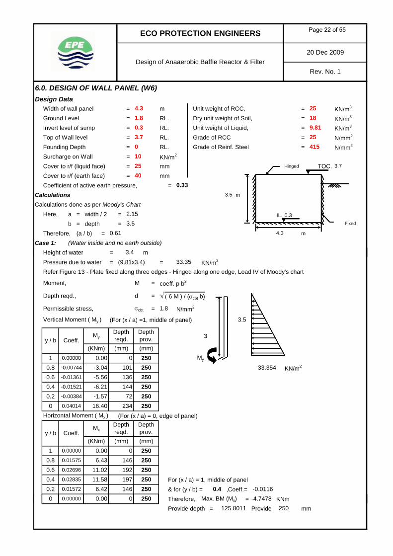
6.0. DESIGN OF WALL PANEL (W6)Design Data
Width of wall panel = m Unit weight of RCC, = KN/m3
Ground Level = RL. Dry unit weight of Soil, = KN/m3
Invert level of sump = RL. Unit weight of Liquid, = KN/m3
Top of Wall level = RL. Grade of RCC = N/mm2
Founding Depth = RL. Grade of Reinf. Steel = N/mm2
Surcharge on Wall = KN/m2
Cover to r/f (liquid face) = mm Hinged TOC.Cover to r/f (earth face) = mmCoefficient of active earth pressure, =
Calculations m
Calculations done as per Moody's ChartHere, a = width / 2 = IL.
b = depth =Therefore, (a / b) = m
Case 1: (Water inside and no earth outside)Height of water = m
0
3 4
25189.81
ECO PROTECTION ENGINEERS
Design of Anaaerobic Baffle Reactor & Filter
25415
0.3
20 Dec 2009
Rev. No. 1
4.31.8
3.7
2540
10
0.33
3.7
3.5
3.5
2.15
0.61
Fixed
4.3
0.3
Height of water = mPressure due to water = (9.81x3.4) = KN/m2
Refer Figure 13 - Plate fixed along three edges - Hinged along one edge, Load IV of Moody's chart
Moment, M = coeff. p b2
Depth reqd., d = √ ( 6 M ) / (σcbt b)
Permissible stress, = N/mm2
Vertical Moment ( My ) (For (x / a) =1, middle of panel)
3
KN/m2
Horizontal Moment ( Mx ) (For (x / a) = 0, edge of panel)
For (x / a) = 1, middle of panel& for (y / b) = ,Coeff.=Therefore, Max. BM (Mx) = KNm
1.8
250
(mm)
3.5
My250
-4.7478
-5.56250
250
3.4
Depth reqd.
33.35
0.40.2
-0.01521
-0.00384
-6.210.6
1
Coeff.My
(mm)
σcbt
00.8
0.00000
-0.00744 -3.04
(KNm)0.00
y / b(mm)
Depth prov.
y / b Coeff.Mx
Depth reqd.
(KNm)
101
-1.57
136144
-0.01361 25033.354250
72 2500 0.04014 16.40 234
(mm)
Depth prov.
0.6 0.02696
1 0.00000 0.00 0
0.4 0.02835 11.58 197
0.8 0.01575 6.43 146
-0.0116
11.02 192
0.2 0.01572 6.42 146 0.40 0.00000 0.00 0
250250250
250
250
Provide depth = Provide mm125.8011 250
Page 22 of 55

ECO PROTECTION ENGINEERS
Design of Anaaerobic Baffle Reactor & Filter20 Dec 2009
Rev. No. 1
Reinforcement Details for liquid pressureAst = M / (σst j d) For Fe415 steel,Ast vertical at bottom = 16400662 / (150 x 0.872 x 221) Liquid face,
on liquid face = mm2 = N/mm2
Ast vertical at 0.2 H from = 1567338 / (190 x 0.89 x 206) j =bottom on earth face = mm2 Earth face,
Ast horizontal at 0.4H from = 11584244 / (150 x 0.872 x 213) = N/mm2
bottom on liquid face = mm2 j =Ast horizontal at 0.4H from = 4747775 / (190 x 0.89 x 198)
bottom on earth face = mm2
Case 2: (Earth outside & Tank empty condition)Height of earth = ( 1.8 ) - ( 0 ) = mPressure due to earth = 0.33 x 18 x 1.8 = KN/m2
Pressure due to surcharge = 0.33 x 10 = KN/m2
Equivalent pressure triangular,1 8^2 / 6 ((10 692 1 8^2 / 6) + (3 3 1 8^2 / 2))
σst 1500.872
142
416σst
567
190
1.810.692
3.3
0.89
45
p x 1.8^2 / 6 = ((10.692 x 1.8^2 / 6) + (3.3 x 1.8^2 / 2))Therefore, p = KN/m2
Vertical Moment ( My ) (For (x / a) =1, middle of panel) Pressure from outside
Equivalent Pressure
Horizontal Moment ( Mx ) (For (x / a) = 0, edge of panel)
m
For (x / a) = 1, middle of panel& for (y / b) = ,Coeff.=Therefore, Max. BM (Mx) = KNmProvide depth = mm
94
59
1.8
250
0 250 -0.7753
mm throughout250
79
Provide of thicknesswall
0.4
0 0.00000 0.000.2 0.01572 1.05
250
My1.890.02835
0.8 0.01575 1.05 590.6 0.02696 1.80 77
0.00000 0.00(KNm)
Depth reqd.(mm)
0
Depth prov.
0
y / b
1
10.692250
Coeff.Mx
-0.50
-1.010.6 -0.01361
0.04014 2.68
0.40.2 -0.00384 -0.26
-0.00744
250-0.91 55 250
-0.01521
1 0.00000
58
0.8
(mm)0.00 0 250 +
FGL
y / b Coeff.My
Depth reqd.
(KNm)
1.8
20.592
(mm)
41
29
m
250FGL
250
My
250250 -0.0116
250
Depth prov.
KN/m2
3.3
20.592
0.4
(mm)250
50.835 Provide
Page 23 of 55

ECO PROTECTION ENGINEERS
Design of Anaaerobic Baffle Reactor & Filter20 Dec 2009
Rev. No. 1
Reinforcement Details for earth pressureFor Fe415 steel,Liquid face, = N/mm2 ; j =Earth face, = N/mm2 ; j =Ast = M / (σst j d) At 0.8H
Ast vertical at bottom = 2678064 / (190 x 0.89 x 206)on earth face = mm2 At 0.6H
Ast vertical at 0.2 H from = 255931 / (150 x 0.872 x 221)bottom on liquid face = mm2
Ast horizontal at 0.4 H from = 1891591 / (190 x 0.89 x 198)bottom on earth face = mm2
Ast horizontal at 0.4 H from = 775264 / (150 x 0.872 x 213) At 0.2H
bottom on liquid face = mm2
Direct Tension & ShearFrom Moody's chart, Rx =
Ry at bottom = Ry at top =Direct Hori. Tension in Wall = Rx p b = 0.2523 x 20.592 x 3.5
77
σst
9
σst 0.890.872
190150
0.0896
At 0.4H
250
0.349
250
WALL SECTION
28
250
250
250
0.2523
56
Direct Hori. Tension in Wall = Rx p b = 0.2523 x 20.592 x 3.5= KN/m
Shear at base of Wall = Ry p b = 0.349 x 20.592 x 3.5= KN/m
Shear at top of Wall = Ry p b = 0.0896 x 20.592 x 3.5= KN/m
Design of Wall for Direct Tension & BendingMaximum bending moment, M = KNm / m For M25 concrete,Horizontal Tension in Wall, T = KN / m = N//mm2
= N//mm2
Approximate depth of section, d = 2 =For Fe415 steel,
= N//mm2
= mm < mme = M / T = 11.584 / 16.324 = m
= mmHence line of action of force lies outside the effective depth
d1 = 250 - 25 - (10 / 2) = mmE = e - d1 + (d / 2) = 709.63 - 220 + (250 / 2) For Fe415 steel,
= mm Liquid face,M1 = T x E = 16.324 x 0.615 = N/mm2
= KNm j =Ast (horizontal steel) reqd., =
= mm2 / metre height
Reinforcement Details to provide
11.584
+
250
σct bm
25.153
6.458
220
615
2 σct bT
203
1500.872
0.7096
T
1.3
709.63
16.324
σst
σst j d1
458
σst+
M1 T
18.184
σct
1.8
+
σcbt
10.04
10.98
150σst
6 M2 σct b
pMin. Ast for mm thick wall Xn = (0.206/100) x 1000 x 250 = mm2
Min. Ast on each face = mm2
515257.5
250
Page 24 of 55

ECO PROTECTION ENGINEERS
Design of Anaaerobic Baffle Reactor & Filter20 Dec 2009
Rev. No. 1
Reinforcement Details to provideVertical Reinforcement
Ast at bottom on liquid face = mm2
Provide Y mm c/c (Ast prov. = mm2 ) Ast at 0.2H from bottom on liquid face = mm2
Provide Y mm c/c (Ast prov. = mm2 ) Ast at bottom on earth face = mm2
Provide Y mm c/c (Ast prov. = mm2 ) Ast at 0.2H from bottom on earth face = mm2
Provide Y mm c/c (Ast prov. = mm2 )
Horizontal reinforcementAst at 1 H from bottom on liquid face at middle of wall = mm2
Provide Y mm c/c (Ast prov. = mm2 ) Ast at 0.2H from bottom on liquid face at edge of wall = mm2
Y (Ast prov. = mm2 ) Ast at 0.4H from bottom on earth face at middle of wall = mm2
P id Y / (A prov = 2 )
10 @
10 @ 150458524@
280
150
567
10
125
10 @ 150
10 @ 280
10 @
10 @ 250
524
257.5280
524
257.5
257.5
280
257.5
257.5
628
314
Provide Y mm c/c (Ast prov. = mm2 ) Ast at 0.4H from bottom on earth face at edge of wall = mm2
Y (Ast prov. = mm2 ) 10 @ 150
10 @ 150 524
524458
Page 25 of 55
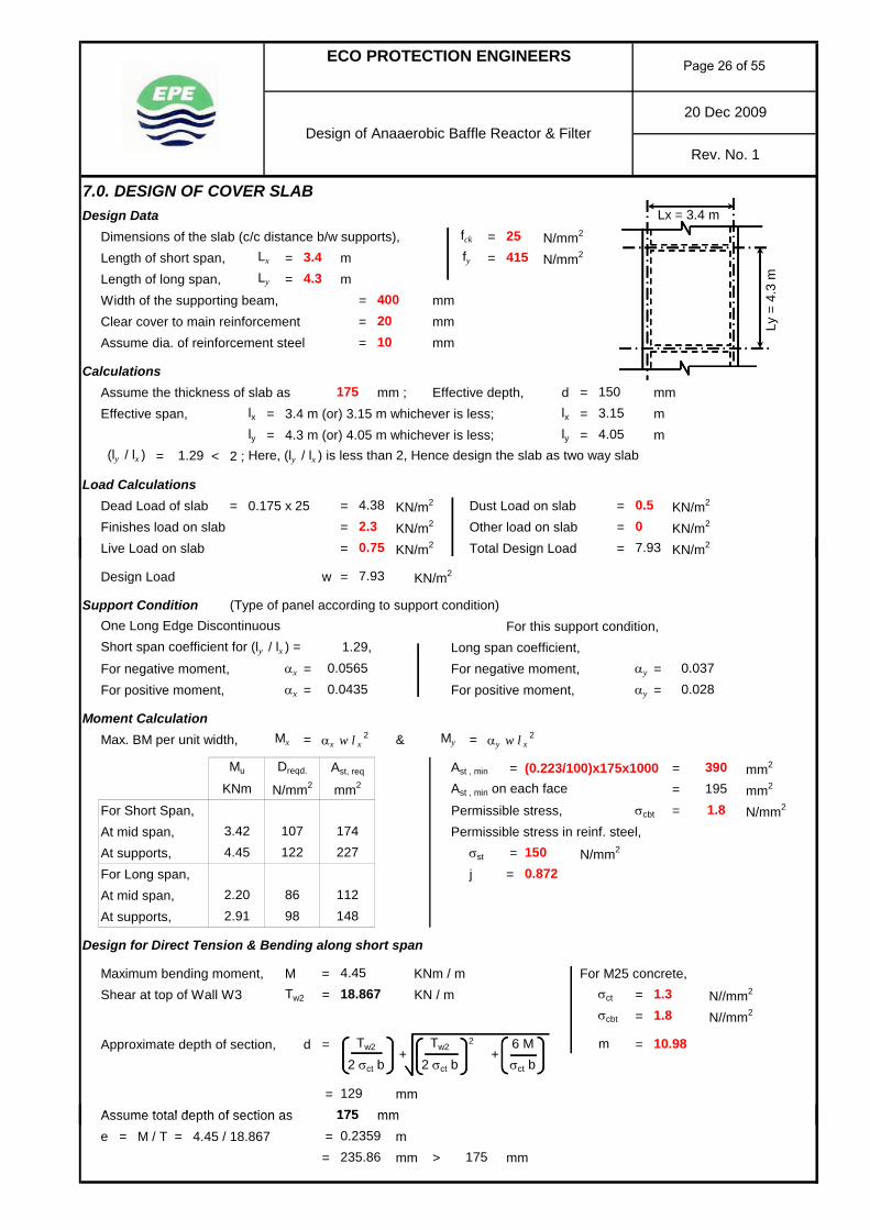
7.0. DESIGN OF COVER SLABDesign Data
Dimensions of the slab (c/c distance b/w supports), = N/mm2
Length of short span, = m = N/mm2
Length of long span, = mWidth of the supporting beam, = mmClear cover to main reinforcement = mmAssume dia. of reinforcement steel = mm
CalculationsAssume the thickness of slab as mm ; Effective depth, d = mmEffective span, lx = 3.4 m (or) 3.15 m whichever is less; lx = m
ly = 4.3 m (or) 4.05 m whichever is less; ly = m= < 2 ; Here, (ly / lx ) is less than 2, Hence design the slab as two way slab
Load CalculationsDead Load of slab = 0.175 x 25 = KN/m2 Dust Load on slab = KN/m2
Finishes load on slab = KN/m2 Other load on slab = KN/m2
Live Load on slab = KN/m2 Total Design Load = KN/m2
1.29(ly / lx )
4.382.30.75
0.507.93
Design of Anaaerobic Baffle Reactor & FilterRev. No. 1
3.154.05
Ly =
4.3
mLy 4.3Lx
25fck
Lx = 3.4 m
20 Dec 2009
ECO PROTECTION ENGINEERS
150175
10
415fy3.4
40020
g
Design Load w = KN/m2
Support Condition (Type of panel according to support condition)For this support condition,
Short span coefficient for (ly / lx ) = Long span coefficient,For negative moment, αx = For negative moment, αy =For positive moment, αx = For positive moment, αy =
Moment CalculationMax. BM per unit width, = αx w l x
2 & = αy w l x2
Ast, req Ast , min = (0.223/100)x175x1000 = mm2
Ast , min on each face = mm2
For Short Span, Permissible stress, σcbt = N/mm2
At mid span, Permissible stress in reinf. steel,At supports, σst = N/mm2
For Long span, j =At mid span,At supports,
Design for Direct Tension & Bending along short span
Maximum bending moment, M = KNm / m For M25 concrete,Shear at top of Wall W3 Tw2 = KN / m = N//mm2
= N//mm2
Approximate depth of section, d = 2 =
= mmAssume total depth of section as mm
One Long Edge Discontinuous
7.93
Mx My
1.29,0.05650.0435
0.0370.028
3901951.8
Mu
3.42 174227
Dreqd.
107122
1.8
Tw2+
Tw2+
6 M m 10.98
2.20 86 112
σcbt
129
KNm N/mm2 mm2
1.3
4.45
2.91 98 148
σct
1500.872
4.4518.867
2 σct b 2 σct b σct b
175Assume total depth of section as mme = M / T = 4.45 / 18.867 = m
= mm > mm235.86
1750.2359
175
Page 26 of 55

Design of Anaaerobic Baffle Reactor & FilterRev. No. 1
20 Dec 2009
ECO PROTECTION ENGINEERS
The line of action of force lies outside the effective depthd1 = 175 - 20 - (10 / 2) = mmE = e - d1 + (d / 2) = 235.86 - 150 + (175 / 2) For Fe415 steel,
= mm Liquid face,M1 = T x E = 18.867 x 0.173 = N/mm2
= KNm j =Ast reqd., =
= mm2 / metre length
Design for Direct Tension along long spanMaximum bending moment, M = KNm / m For M25 concrete,Shear at top of Wall W1 Tw1 = KN / m = N//mm2
= N//mm2
Approximate depth of section, d = 2 =
= mmAssume total depth of section as mm
103
150
173σst 150
3.26 0.872
292
M1+
Tσst j d1 σst
σct 1.3σcbt 1.8
2.9111.084
Tw2+
10.982 σct b 2 σct b σct b
Tw2+
6 M m
175Assume total depth of section as mme = M / T = 2.91 / 11.084 = m
= mm > mmThe line of action of force lies outside the effective depthd1 = 175 - 20 - (10 / 2) = mmE = e - d1 + (d / 2) = 262.54 - 150 + (175 / 2) For Fe415 steel,
= mm Liquid face,M1 = T x E = 11.084 x 0.2 = N/mm2
= KNm j =Ast reqd., =
= mm2 / metre length
Reinforcement detailsProvide Y @ mm C/C, (T&B) along short span (Ast pro. = mm2 )Provide Y @ mm C/C, (T&B) along long span (Ast pro. = mm2 )
1508251
1750.2625
175
150
σst 150
262.54
200
187
8
0.872M1
+T
σst j d1 σst
2.22
335200
Page 27 of 55

8.0. DESIGN OF SLAB SUPPORTING FILTER MEDIADesign Data
Dimensions of the slab (c/c distance b/w supports), = N/mm2
Length of short span, = m = N/mm2
Length of long span, = mWidth of end support = mmWidth of support near to end support = mmClear cover to main reinforcement = mmAssume dia. of reinforcement steel = mm
CalculationsAssume the thickness of slab as mm ; Effective depth of slab = mmEffective span of slab, lx = clear span lx = m
ly = clear span ly = m= > 2
Here, (ly / lx) is greater than 2, Hence design the slab as one way slab
Load CalculationsDead Load of slab = 0.125 x 25 = kN/m2 BM Coeff. In mid-span = 1 /
2
375
25
ECO PROTECTION ENGINEERS
Design of Anaerobic Baffle Reactor & Filter
415fy
375
20
3(ly / lx)
8
101
2
8
125
8
3.375
3.1250
1.5
Lx=3
.375
m
Ly = 1.875m
Rev. No. 1
20 Dec 2009
fck
Lx
Ly
1.875
Finishes load on slab = kN/m2 Design BM, M = W l / KN mLive Load on slab = kN/m2 = (18.235 x 1.5) /Other load on slab = kN/m2 = KN mDesign Load = kN/m2
Total Design load per m width = kN/m For M25 concrete,Depth reqd., d = √ ( 6 M ) / (σcbt b) = N//mm2
= mmTherefore, thickness of slab = mm
Reinforcement Details For Fe415 steel,Liquid face,
= N/mm2
= mm2 / metre length j =
Reinforcement Details to provideAst at span = 3420000 / (150 x 0.872 x 101) Ast min. = (0.2343/100) b D
= mm2 = mm2
Ast (along short dir.) = mm2
Ast (along long dir.) = mm2
Provide Y @ mm C/C along short dir. (Ast pro. = mm2 )Provide Y @ mm C/C along long dir. (Ast pro. = mm2 )
293
0.872
1.8σcbt
18.235
150σstσst j dM
15.11
88
335335
15088 150
293
=Area of Reinf. Steel, Ast reqd.,
107125
259
259
293
18.2353.42
00
Page 28 of 55

9.0. DESIGN OF WALL FOOTING FOR WALL (W1)Design Data
Founding depth of wall footing = m RL.FGL = m RL.Top of wall level = m RL.IL. of tank = m RL.
CalculationsThickness of wall above base slab = mThickness of wall below base slab = mThickness of base slab = mThickness of cover slab = mWidth of footing = mOutside projection of footing = mInside projection of footing = mThickness of footing = m
EL. 3.875
0.175
0.3
0.3
0.43750.3
-1.5
3.8751.8
0.3
1.1750.4375
20 Dec 2009
ECO PROTECTION ENGINEERS
Design of Anaerobic Baffle Reactor & FilterRev. No. 1
0.15
EL. 1.8
EL. 0.3
Point O
C/S OF WALL FOOTING
300
EL. -1.5437.5
1175
150
300
300
Page 29 of 55

20 Dec 2009
ECO PROTECTION ENGINEERS
Design of Anaerobic Baffle Reactor & FilterRev. No. 1
1.8263 Weight of cover slab 0.4375 x 0.175 x 25 =
15.7510.588
1.5681.64
26.81
6.609
0.219
5.177
5.169
11.2931.5 x 0.4375 x 18 =
1.91
0.588
0.588
11.25
0.956
23.63
11.81
8.81
6
Footing
0.956
Weight of water
Weight of earth inside footing projection
3 x 0.4375 x 18 =
Load in kN/mS.No. Component
5
7Weight of earth outside footing projection
Weight of base slab
Main wall above base slab
Main wall below base slab
1
2
4
Leverarm in m Moment in kNm/m about O
0.4375 x 0.15 x 25 =
1.5 x 0.3 x 25 =
0.956
3.58 x 0.3 x 25 =
1.175 x 0.3 x 25 =
Case 1 No earth outside and water inside condition
Vertical load, P = 26.81+1.64+1.91+11.25+8.8125+11.81+15.34= kN
Moment due to above load, M = 15.75+1.57+1.83+6.61+5.18+11.29 + 14.67-21.9= kNm
Width of the footing, L = mDistance of resultant, x = M / P = 34.99 / 77.57 = mEccentricity, e = | (L / 2) - x | = m
e = mm < (L/6) = 196 mm ; No Tension
Soil pressure, p = (P/L)(1 ± (6e/L))
Max. soil pressure, pmax = (P/L)(1 + (6e/L)) Min. soil pressure, pmin = (P/L)(1 - (6e/L))= kN/m2 = kN/m2
kN/m2 kN/m2
10Moment due to earth outside the tank
0.13650.45
-21.9
0.25
14.669
20
3.58 x 0.4375 x 9.81 = 0.95615.34Weight of water inside the tank
112.03
1.18
136.5
9Moment due to water inside the tank
77.57
8
20 112.03
34.99
kN/m kN/m
kN/m2 kN/m2
77.76454.266
Page 30 of 55
20 Dec 2009
ECO PROTECTION ENGINEERS
Design of Anaerobic Baffle Reactor & FilterRev. No. 1
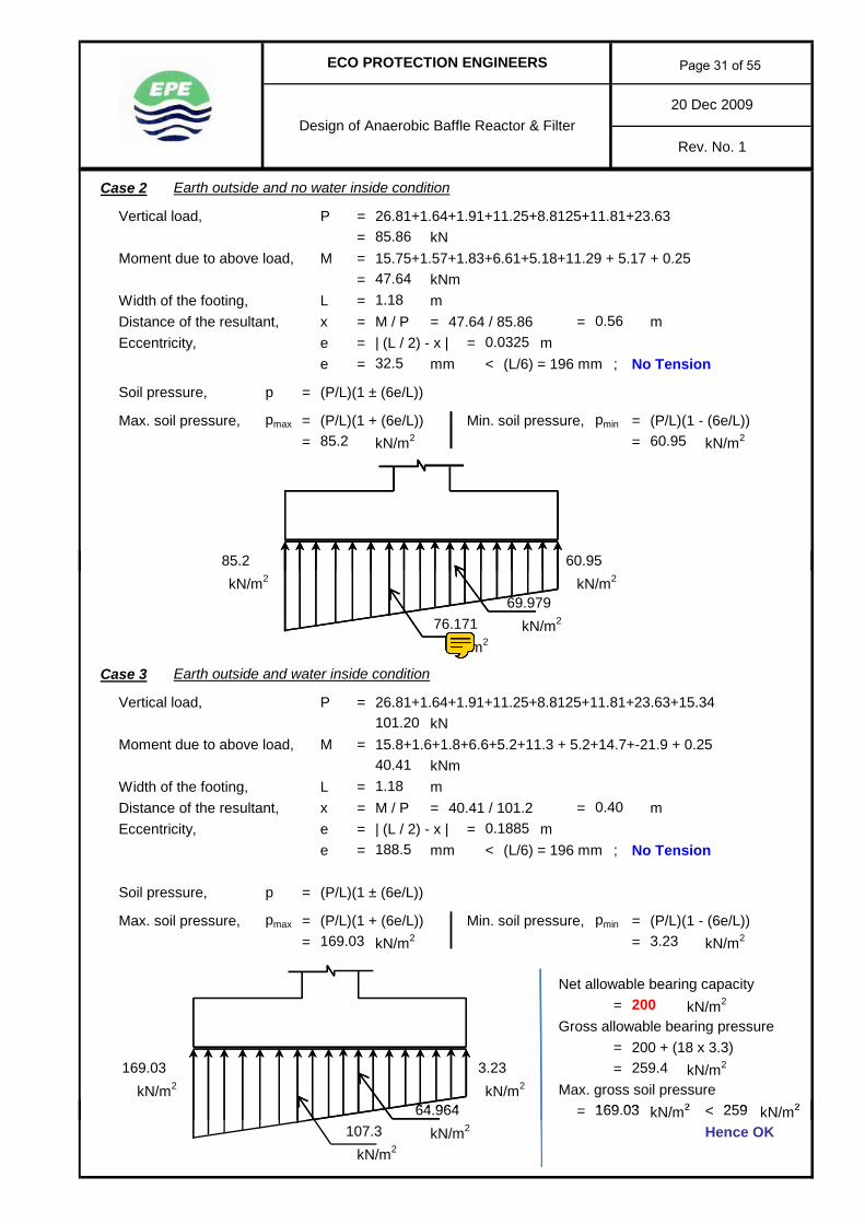
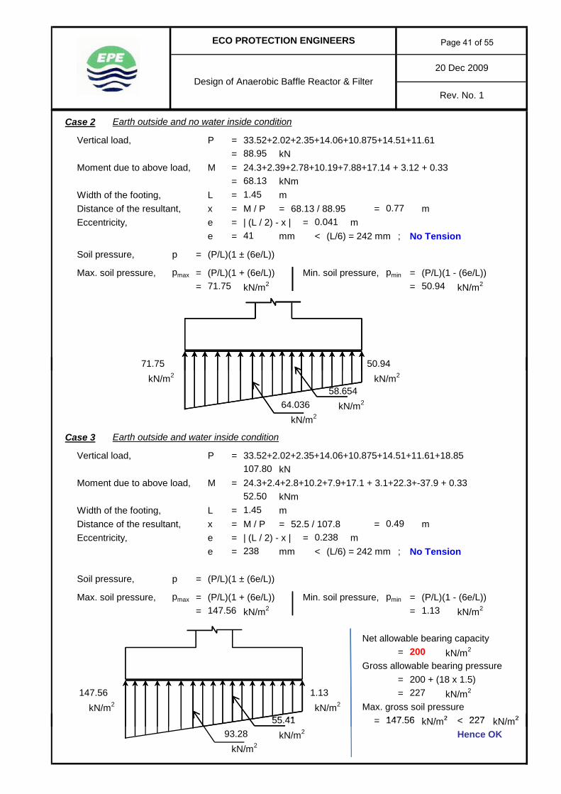
Case 2 Earth outside and no water inside condition
Vertical load, P = 26.81+1.64+1.91+11.25+8.8125+11.81+23.63= kN
Moment due to above load, M = 15.75+1.57+1.83+6.61+5.18+11.29 + 5.17 + 0.25= kNm
Width of the footing, L = mDistance of the resultant, x = M / P = 47.64 / 85.86 = mEccentricity, e = | (L / 2) - x | = m
e = mm < (L/6) = 196 mm ; No Tension
Soil pressure, p = (P/L)(1 ± (6e/L))
Max. soil pressure, pmax = (P/L)(1 + (6e/L)) Min. soil pressure, pmin = (P/L)(1 - (6e/L))= kN/m2 = kN/m2
47.64
85.86
1.18
60.95
32.5
85.2
0.560.0325
kN/m2 kN/m2
kN/m2
kN/m2
Case 3 Earth outside and water inside condition
Vertical load, P = 26.81+1.64+1.91+11.25+8.8125+11.81+23.63+15.34kN
Moment due to above load, M = 15.8+1.6+1.8+6.6+5.2+11.3 + 5.2+14.7+-21.9 + 0.25kNm
Width of the footing, L = mDistance of the resultant, x = M / P = 40.41 / 101.2 = mEccentricity, e = | (L / 2) - x | = m
e = mm < (L/6) = 196 mm ; No Tension
Soil pressure, p = (P/L)(1 ± (6e/L))
Max. soil pressure, pmax = (P/L)(1 + (6e/L)) Min. soil pressure, pmin = (P/L)(1 - (6e/L))= kN/m2 = kN/m2
Net allowable bearing capacity= kN/m2
Gross allowable bearing pressure= 200 + (18 x 3.3)= kN/m2
kN/m2 kN/m2 Max. gross soil pressurekN/ 2 < kN/ 2259169 03
200
259.4
101.20
40.411.18
188.5
64 964
3.23
85.2
76.17169.979
0.40
169.03 3.23
169.03
0.1885
60.95
= kN/m2 < kN/m2
kN/m2 Hence OKkN/m2
259169.0364.964107.3
Page 31 of 55

20 Dec 2009
ECO PROTECTION ENGINEERS
Design of Anaerobic Baffle Reactor & FilterRev. No. 1
Design of cantilever projection of footing Characteristic strength of materialDesign Data Grade of Concrete, fck = N/mm2
Thickness of footing, D = m Grade of Reinf.steel, fy = N/mm2
Projection of footing, l = m Cover to Reinf. steelThickness of soil over footing proj. = m Earth face = mmPartial safety factor (Long Term) =
CalculationsCase 1
Gross soil pressure at face of footing = kN/m2
Gross soil pressure at edge of footing = kN/m2
Net soil pressure for design = {1.5 x (77.7635106382979 - (25 x 0.3) - (18 x 3))}at the face of the footing w 1 = kN/m2
Net soil pressure for design = {1.5 x (112.03 - (25 x 0.3) - (18 x 3))}at the edge of the footing w 2 = kN/m2
(w 2 - w 1) l2
= kNm kN/m2 kN/m2
50
0.3
24.4
25415
1.5
112.03
75.8
0.4375
77.764
3
BM at the face of wall,3
M2
w 1 l2
= +24.475.8
0.4375
5 61= kNm kN/m2 kN/m2
Case 2Gross soil pressure at face of footing = kN/m2
Gross soil pressure at edge of footing = kN/m2
Net soil pressure for design = {1.5 x (76.1707446808511 - (25 x 0.3) - (18 x 3))}at the face of the footing w 1 = kN/m2
Net soil pressure for design = {1.5 x (85.2 - (25 x 0.3) - (18 x 3))}at the edge of the footing w 2 = kN/m2
(w 2 - w 1) l2
= kNm kN/m2 kN/m2
Case 3Gross soil pressure at face of footing = kN/m2
Gross soil pressure at edge of footing = kN/m2
Net soil pressure for design = {1.5 x (107.3 - (25 x 0.3) - (18 x 3))}at the face of the footing w 1 = kN/m2
Net soil pressure for design = {1.5 x (169.03 - (25 x 0.3) - (18 x 3))}at the edge of the footing w 2 = kN/m2
(w 2 - w 1) l2
= kNm kN/m2 kN/m2
Design Bending Moment, Mu = kNmlet diameter of reinf.steel be = mm ; Eff. Depth, d = mmM / bd2 ; p %
0.4375
BM at the face of wall, M =2
76.171
22.01
5.61
68.7
2.97
85.2
22.01
35.55
+0.4375
3 35.55w 1 l
2
245
107.3169.03
68.7
161.3
2 3 161.3w 1 l
2
+BM at the face of wall, M =
0 0488
12.48
12.4810
0 21Mu / bd2 = ; pt = %pt, min = % of overall c/s area i.e. bD0.12
0.04880.21
Page 32 of 55

20 Dec 2009
ECO PROTECTION ENGINEERS
Design of Anaerobic Baffle Reactor & FilterRev. No. 1
Reinforcement detailsAst = mm2 at bottomAst = mm2 at top face
@ mm c/c radially at bottom (Ast pro. = mm2 )
@ mm c/c radially at top (Ast pro. = mm2 )
@ mm c/c circumf. (T & B) (Ast pro. = mm2 )
Check for ShearCritical section for shear is at a distance of d from the face of wallDistance, l 1 = l - d = m X1
Case 1Pressure, w 1 = kN/m2 ; w 2 = kN/m2
Total shear at section X1-X1 = + (1/2) (w 2 - w 1) l 1
= kN / metre lengthkN/m2 kN/m2
X1Case 2
53.1875.8
0.1925
0.1925
393
393
393
53.18 75.8w 1 l 1
12.41
Provide Y 10 200
360360
Provide Y 10 200
Provide Y 10 200
0.1925
Case 2Pressure, w 1 = kN/m2 ; w 2 = kN/m2
Total shear at section X1-X1 = + (1/2) (w 2 - w 1) l 1
= kN / metre lengthkN/m2 kN/m2
X1Case 3
Pressure, w 1 = kN/m2 ; w 2 = kN/m2
Total shear at section X1-X1 = + (1/2) (w 2 - w 1) l 1
= kN / metre lengthDesign shear, Vu = kN / metre length kN/m2 kN/m2
Percentage of reinf.steel prov. pt = %Shear strength of concrete, τc = N/mm2
Shear stress developed, τv = Vu / bd= N/mm2 < N/mm2 ; Hence OK
Sketch showing reinforcement in footing
Y10 @ 200 mm c/c
Y10 @ 200 mm c/cY10 @ 200 mm c/c (T&B)
27.13 161.3 120.56
35.55 29.59
0.297
27.13
0.11 0.297
0.16
300
0.1925
120.56 161.3w 1 l 1
w 1 l 1
6.27
29.59 35.55
1175
Page 33 of 55
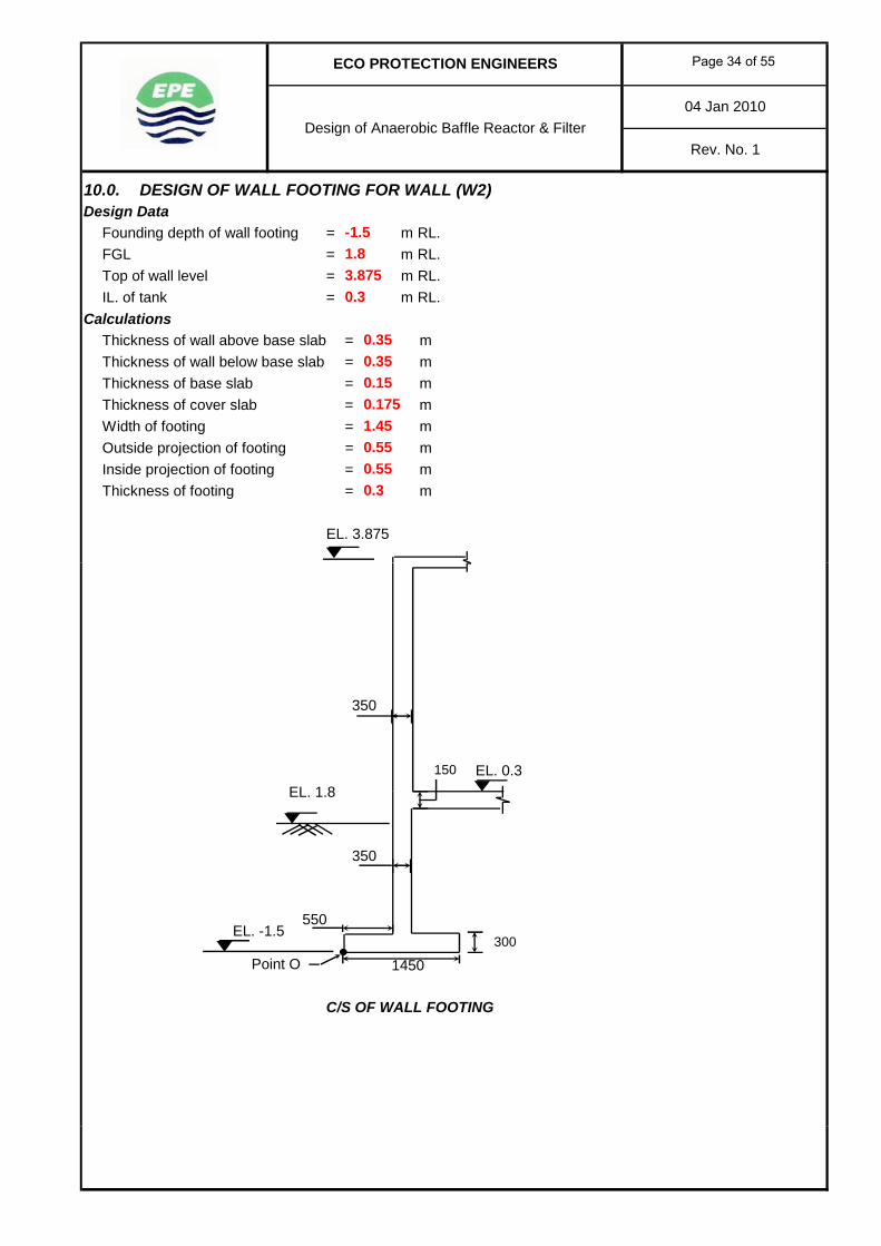
10.0. DESIGN OF WALL FOOTING FOR WALL (W2)Design Data
Founding depth of wall footing = m RL.FGL = m RL.Top of wall level = m RL.IL. of tank = m RL.
CalculationsThickness of wall above base slab = mThickness of wall below base slab = mThickness of base slab = mThickness of cover slab = mWidth of footing = mOutside projection of footing = mInside projection of footing = mThickness of footing = m
EL. 3.875
04 Jan 2010
ECO PROTECTION ENGINEERS
Design of Anaerobic Baffle Reactor & FilterRev. No. 1
0.15
-1.5
3.8751.8
0.35
1.450.55
0.3
0.35
0.550.3
0.175
EL. 0.3EL. 1.8
Point O
C/S OF WALL FOOTING
1450
150
300
350
550EL. -1.5
350
Page 34 of 55

04 Jan 2010
ECO PROTECTION ENGINEERS
Design of Anaerobic Baffle Reactor & FilterRev. No. 1
1.175
3.58 x 0.35 x 25 =
1.45 x 0.3 x 25 =
Leverarm in m Moment in kNm/m about O
0.55 x 0.15 x 25 =
1.5 x 0.35 x 25 =
Weight of base slab
Main wall above base slab
Main wall below base slab
1
2
4
Weight of earth outside footing projection
3 x 0.55 x 18 =
Load in kN/mS.No. Component
5
7
6
Footing
1.175
Weight of water
Weight of earth inside footing projection
2.41
0.725
0.725
13.13
1.175
29.70
14.85
10.88
9.519
0.275
7.884
8.168
17.4491.5 x 0.55 x 18 =
0.725
2.4212.06
31.28
2.8323 Weight of cover slab 0.55 x 0.175 x 25 =
22.678
Case 1 No earth outside and water inside condition
Vertical load, P = 31.28+2.06+2.41+13.13+10.875+14.85+19.29= kN
Moment due to above load, M = 22.68+2.42+2.83+9.52+7.88+17.45 + 22.67-33.74= kNm
Width of the footing, L = mDistance of resultant, x = M / P = 51.71 / 93.9 = mEccentricity, e = | (L / 2) - x | = m
e = mm < (L/6) = 242 mm ; No Tension
Soil pressure, p = (P/L)(1 ± (6e/L))
Max. soil pressure, pmax = (P/L)(1 + (6e/L)) Min. soil pressure, pmin = (P/L)(1 - (6e/L))= kN/m2 = kN/m2
kN/m2 kN/m2
51.71
18.13 111.38
9Moment due to water inside the tank
93.90
8
111.38
1.45
174
Weight of water inside the tank 3.58 x 0.55 x 9.81 = 1.17519.29 22.666
18.13
0.1740.55
-33.74
0.3110Moment due to earth outside the tank
kN/m kN/m
kN/m2 kN/m2
76.00953.501
Page 35 of 55
04 Jan 2010
ECO PROTECTION ENGINEERS
Design of Anaerobic Baffle Reactor & FilterRev. No. 1
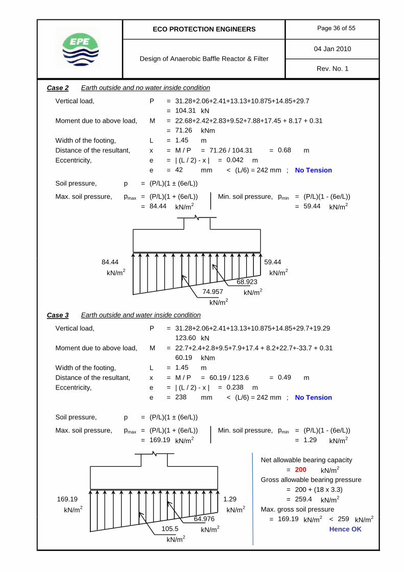
Case 2 Earth outside and no water inside condition
Vertical load, P = 31.28+2.06+2.41+13.13+10.875+14.85+29.7= kN
Moment due to above load, M = 22.68+2.42+2.83+9.52+7.88+17.45 + 8.17 + 0.31= kNm
Width of the footing, L = mDistance of the resultant, x = M / P = 71.26 / 104.31 = mEccentricity, e = | (L / 2) - x | = m
e = mm < (L/6) = 242 mm ; No Tension
Soil pressure, p = (P/L)(1 ± (6e/L))
Max. soil pressure, pmax = (P/L)(1 + (6e/L)) Min. soil pressure, pmin = (P/L)(1 - (6e/L))= kN/m2 = kN/m2
0.0420.68
84.44
42
104.31
1.45
59.44
71.26
kN/m2 kN/m2
kN/m2
kN/m2
Case 3 Earth outside and water inside condition
Vertical load, P = 31.28+2.06+2.41+13.13+10.875+14.85+29.7+19.29kN
Moment due to above load, M = 22.7+2.4+2.8+9.5+7.9+17.4 + 8.2+22.7+-33.7 + 0.31kNm
Width of the footing, L = mDistance of the resultant, x = M / P = 60.19 / 123.6 = mEccentricity, e = | (L / 2) - x | = m
e = mm < (L/6) = 242 mm ; No Tension
Soil pressure, p = (P/L)(1 ± (6e/L))
Max. soil pressure, pmax = (P/L)(1 + (6e/L)) Min. soil pressure, pmin = (P/L)(1 - (6e/L))= kN/m2 = kN/m2
Net allowable bearing capacity= kN/m2
Gross allowable bearing pressure= 200 + (18 x 3.3)= kN/m2
kN/m2 kN/m2 Max. gross soil pressure2 2
0.49
169.19 1.29
169.19
0.238
59.44
74.95768.923
84.44
1.29
1.45
238
64 976
123.60
60.19
169 19
200
259.4
259= kN/m2 < kN/m2
kN/m2 Hence OKkN/m2
105.564.976 169.19 259
Page 36 of 55
04 Jan 2010
ECO PROTECTION ENGINEERS
Design of Anaerobic Baffle Reactor & FilterRev. No. 1
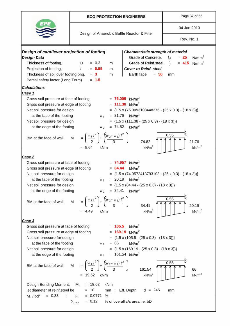
Design of cantilever projection of footing Characteristic strength of materialDesign Data Grade of Concrete, fck = N/mm2
Thickness of footing, D = m Grade of Reinf.steel, fy = N/mm2
Projection of footing, l = m Cover to Reinf. steelThickness of soil over footing proj. = m Earth face = mmPartial safety factor (Long Term) =
CalculationsCase 1
Gross soil pressure at face of footing = kN/m2
Gross soil pressure at edge of footing = kN/m2
Net soil pressure for design = {1.5 x (76.0093103448276 - (25 x 0.3) - (18 x 3))}at the face of the footing w 1 = kN/m2
Net soil pressure for design = {1.5 x (111.38 - (25 x 0.3) - (18 x 3))}at the edge of the footing w 2 = kN/m2
(w 2 - w 1) l2
= kNm kN/m2 kN/m2
2w 1 l
2
= +21.7674.82
0.55
8 64
BM at the face of wall,3
M
3
21.76
25415
1.5
111.38
74.82
0.55
76.009
0.3
50
= kNm kN/m kN/m
Case 2Gross soil pressure at face of footing = kN/m2
Gross soil pressure at edge of footing = kN/m2
Net soil pressure for design = {1.5 x (74.9572413793103 - (25 x 0.3) - (18 x 3))}at the face of the footing w 1 = kN/m2
Net soil pressure for design = {1.5 x (84.44 - (25 x 0.3) - (18 x 3))}at the edge of the footing w 2 = kN/m2
(w 2 - w 1) l2
= kNm kN/m2 kN/m2
Case 3Gross soil pressure at face of footing = kN/m2
Gross soil pressure at edge of footing = kN/m2
Net soil pressure for design = {1.5 x (105.5 - (25 x 0.3) - (18 x 3))}at the face of the footing w 1 = kN/m2
Net soil pressure for design = {1.5 x (169.19 - (25 x 0.3) - (18 x 3))}at the edge of the footing w 2 = kN/m2
(w 2 - w 1) l2
= kNm kN/m2 kN/m2
Design Bending Moment, Mu = kNmlet diameter of reinf.steel be = mm ; Eff. Depth, d = mm
/ 2 %
BM at the face of wall, M =
0 0771
19.62
19.6210
0 33245
105.5169.19
66
161.54
2 3 161.54w 1 l
2
+66
4.49
84.44
20.19
34.41
+0.55
3 34.41w 1 l
2
74.957
20.19
8.64
BM at the face of wall, M =2
0.55
Mu / bd2 = ; pt = %pt, min = % of overall c/s area i.e. bD
0.07710.330.12
Page 37 of 55
04 Jan 2010
ECO PROTECTION ENGINEERS
Design of Anaerobic Baffle Reactor & FilterRev. No. 1
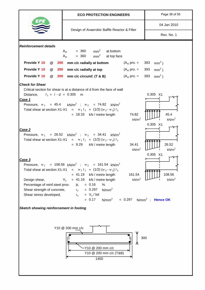
Reinforcement detailsAst = mm2 at bottomAst = mm2 at top face
@ mm c/c radially at bottom (Ast pro. = mm2 )
@ mm c/c radially at top (Ast pro. = mm2 )
@ mm c/c circumf. (T & B) (Ast pro. = mm2 )
Check for ShearCritical section for shear is at a distance of d from the face of wallDistance, l 1 = l - d = m X1
Case 1Pressure, w 1 = kN/m2 ; w 2 = kN/m2
Total shear at section X1-X1 = + (1/2) (w 2 - w 1) l 1
= kN / metre lengthkN/m2 kN/m2
X1Case 2
Provide Y 10 200
0.305
Provide Y 10 200
360360
w 1 l 1
18.33
Provide Y 10 200 393
45.4 74.82
0.305
0.305
393
393
45.474.82
Pressure, w 1 = kN/m2 ; w 2 = kN/m2
Total shear at section X1-X1 = + (1/2) (w 2 - w 1) l 1
= kN / metre lengthkN/m2 kN/m2
X1Case 3
Pressure, w 1 = kN/m2 ; w 2 = kN/m2
Total shear at section X1-X1 = + (1/2) (w 2 - w 1) l 1
= kN / metre lengthDesign shear, Vu = kN / metre length kN/m2 kN/m2
Percentage of reinf.steel prov. pt = %Shear strength of concrete, τc = N/mm2
Shear stress developed, τv = Vu / bd= N/mm2 < N/mm2 ; Hence OK
Sketch showing reinforcement in footing
Y10 @ 200 mm c/c
Y10 @ 200 mm c/cY10 @ 200 mm c/c (T&B)
1450
108.56 161.54w 1 l 1
w 1 l 1
9.29
26.52 34.41
0.305
0.297
41.19
0.17 0.297
0.16
300
41.19 161.54 108.56
34.41 26.52
Page 38 of 55
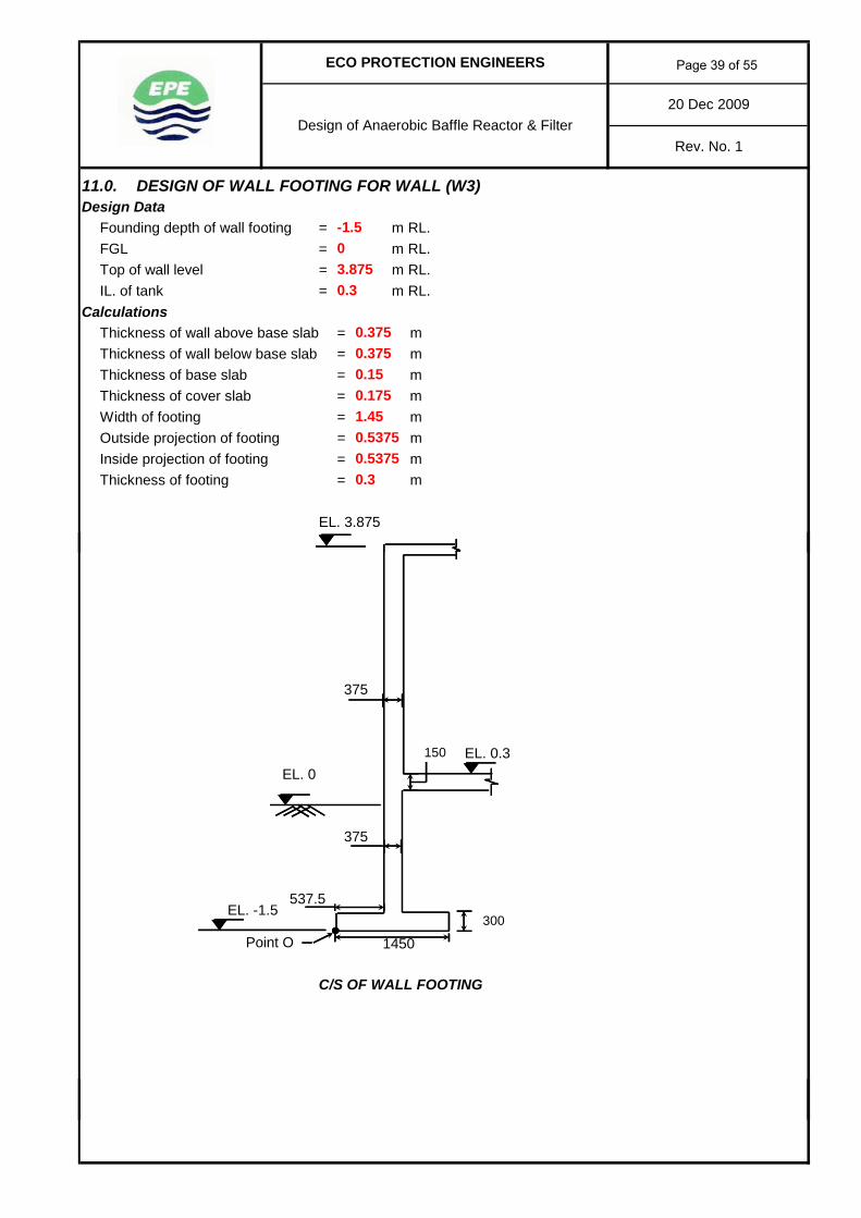
11.0. DESIGN OF WALL FOOTING FOR WALL (W3)Design Data
Founding depth of wall footing = m RL.FGL = m RL.Top of wall level = m RL.IL. of tank = m RL.
CalculationsThickness of wall above base slab = mThickness of wall below base slab = mThickness of base slab = mThickness of cover slab = mWidth of footing = mOutside projection of footing = mInside projection of footing = mThickness of footing = m
EL. 3.875
0.175
0.3
0.375
1.45
-1.5
3.8750
0.53750.53750.3
20 Dec 2009
ECO PROTECTION ENGINEERS
Design of Anaerobic Baffle Reactor & FilterRev. No. 1
0.3750.15
EL. 0.3EL. 0
Point O
C/S OF WALL FOOTING
375
375
EL. -1.5537.5
1450
150
300
Page 39 of 55
20 Dec 2009
ECO PROTECTION ENGINEERS
Design of Anaerobic Baffle Reactor & FilterRev. No. 1
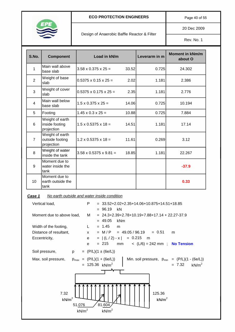
3 Weight of cover slab 0.5375 x 0.175 x 25 =
11.61
1.5 x 0.5375 x 18 =
33.52
1.181 17.14
10.88
24.3020.725
2.386
2.776
10.194
0.269
7.884
3.121.2 x 0.5375 x 18 =
14.51
2.35
0.725
0.725
14.06
1.181
2.02
S.No. Component
5
7Weight of earth outside footing projection
6
Footing
Weight of water
Weight of earth inside footing projection
Weight of base slab
Main wall above base slab
Main wall below base slab
1
2
4
Leverarm in m Moment in kNm/m about O
0.5375 x 0.15 x 25 =
1.5 x 0.375 x 25 =
Load in kN/m
1.181
3.58 x 0.375 x 25 =
1.45 x 0.3 x 25 =
Case 1 No earth outside and water inside condition
Vertical load, P = 33.52+2.02+2.35+14.06+10.875+14.51+18.85= kN
Moment due to above load, M = 24.3+2.39+2.78+10.19+7.88+17.14 + 22.27-37.9= kNm
Width of the footing, L = mDistance of resultant, x = M / P = 49.05 / 96.19 = mEccentricity, e = | (L / 2) - x | = m
e = mm < (L/6) = 242 mm ; No Tension
Soil pressure, p = (P/L)(1 ± (6e/L))
Max. soil pressure, pmax = (P/L)(1 + (6e/L)) Min. soil pressure, pmin = (P/L)(1 - (6e/L))= kN/m2 = kN/m2
kN/m2 kN/m2
10Moment due to earth outside the tank
0.51
-37.9
0.33
22.267
0.215
7.32125.36
1.18118.853.58 x 0.5375 x 9.81 =
9Moment due to water inside the tank
96.19
7.32
8 Weight of water inside the tank
125.36
1.45
215
49.05
kN/m kN/m
kN/m2 kN/m2
81.60451.076
Page 40 of 55
20 Dec 2009
ECO PROTECTION ENGINEERS
Design of Anaerobic Baffle Reactor & FilterRev. No. 1
Case 2 Earth outside and no water inside condition
Vertical load, P = 33.52+2.02+2.35+14.06+10.875+14.51+11.61= kN
Moment due to above load, M = 24.3+2.39+2.78+10.19+7.88+17.14 + 3.12 + 0.33= kNm
Width of the footing, L = mDistance of the resultant, x = M / P = 68.13 / 88.95 = mEccentricity, e = | (L / 2) - x | = m
e = mm < (L/6) = 242 mm ; No Tension
Soil pressure, p = (P/L)(1 ± (6e/L))
Max. soil pressure, pmax = (P/L)(1 + (6e/L)) Min. soil pressure, pmin = (P/L)(1 - (6e/L))= kN/m2 = kN/m2
68.13
88.95
1.45
50.94
41
71.75
0.770.041
kN/m2 kN/m2
kN/m2
kN/m2
Case 3 Earth outside and water inside condition
Vertical load, P = 33.52+2.02+2.35+14.06+10.875+14.51+11.61+18.85kN
Moment due to above load, M = 24.3+2.4+2.8+10.2+7.9+17.1 + 3.1+22.3+-37.9 + 0.33kNm
Width of the footing, L = mDistance of the resultant, x = M / P = 52.5 / 107.8 = mEccentricity, e = | (L / 2) - x | = m
e = mm < (L/6) = 242 mm ; No Tension
Soil pressure, p = (P/L)(1 ± (6e/L))
Max. soil pressure, pmax = (P/L)(1 + (6e/L)) Min. soil pressure, pmin = (P/L)(1 - (6e/L))= kN/m2 = kN/m2
Net allowable bearing capacity= kN/m2
Gross allowable bearing pressure= 200 + (18 x 1.5)= kN/m2
kN/m2 kN/m2 Max. gross soil pressurekN/ 2 < kN/ 2227147 56
200
227
107.80
52.50
1.13
1.45
238
55 41
71.75 50.94
64.03658.654
0.49
147.56 1.13
147.56
0.238
= kN/m2 < kN/m2
kN/m2 Hence OKkN/m2
227147.5655.4193.28
Page 41 of 55
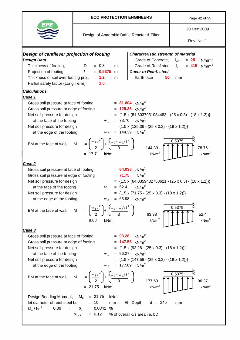
20 Dec 2009
ECO PROTECTION ENGINEERS
Design of Anaerobic Baffle Reactor & FilterRev. No. 1
Design of cantilever projection of footing Characteristic strength of materialDesign Data Grade of Concrete, fck = N/mm2
Thickness of footing, D = m Grade of Reinf.steel, fy = N/mm2
Projection of footing, l = m Cover to Reinf. steelThickness of soil over footing proj. = m Earth face = mmPartial safety factor (Long Term) =
CalculationsCase 1
Gross soil pressure at face of footing = kN/m2
Gross soil pressure at edge of footing = kN/m2
Net soil pressure for design = {1.5 x (81.6037931034483 - (25 x 0.3) - (18 x 1.2))}at the face of the footing w 1 = kN/m2
Net soil pressure for design = {1.5 x (125.36 - (25 x 0.3) - (18 x 1.2))}at the edge of the footing w 2 = kN/m2
(w 2 - w 1) l2
= kNm kN/m2 kN/m2
25415
501.5
125.36
144.39
0.53750.3
78.76
1.2
81.604
BM at the face of wall,3
M2
w 1 l2
= +78.76144.39
0.5375
17 7= kNm kN/m2 kN/m2
Case 2Gross soil pressure at face of footing = kN/m2
Gross soil pressure at edge of footing = kN/m2
Net soil pressure for design = {1.5 x (64.0359482758621 - (25 x 0.3) - (18 x 1.2))}at the face of the footing w 1 = kN/m2
Net soil pressure for design = {1.5 x (71.75 - (25 x 0.3) - (18 x 1.2))}at the edge of the footing w 2 = kN/m2
(w 2 - w 1) l2
= kNm kN/m2 kN/m2
Case 3Gross soil pressure at face of footing = kN/m2
Gross soil pressure at edge of footing = kN/m2
Net soil pressure for design = {1.5 x (93.28 - (25 x 0.3) - (18 x 1.2))}at the face of the footing w 1 = kN/m2
Net soil pressure for design = {1.5 x (147.56 - (25 x 0.3) - (18 x 1.2))}at the edge of the footing w 2 = kN/m2
(w 2 - w 1) l2
= kNm kN/m2 kN/m2
Design Bending Moment, Mu = kNmlet diameter of reinf.steel be = mm ; Eff. Depth, d = mmM / bd2 ; p %
2
0 36
BM at the face of wall, M =
BM at the face of wall,
64.036
17.7
52.48.68
71.75
52.4
63.98
+0.5375
3 63.98w 1 l
2
96.2721.75
21.7510 245
0.5375
2 3 177.69w 1 l
2
M =
0 0842
93.28147.56
96.27
177.69
+
Mu / bd2 = ; pt = %pt, min = % of overall c/s area i.e. bD0.12
0.36 0.0842
Page 42 of 55

20 Dec 2009
ECO PROTECTION ENGINEERS
Design of Anaerobic Baffle Reactor & FilterRev. No. 1
Reinforcement detailsAst = mm2 at bottomAst = mm2 at top face
@ mm c/c radially at bottom (Ast pro. = mm2 )
@ mm c/c radially at top (Ast pro. = mm2 )
@ mm c/c circumf. (T & B) (Ast pro. = mm2 )
Check for ShearCritical section for shear is at a distance of d from the face of wallDistance, l 1 = l - d = m X1
Case 1Pressure, w 1 = kN/m2 ; w 2 = kN/m2
Total shear at section X1-X1 = + (1/2) (w 2 - w 1) l 1
= kN / metre lengthkN/m2 kN/m2
X1Case 2
108.68144.39
393
0.2925
0.2925
w 1 l 1
37.01
393
108.68 144.39
393
360360
Provide Y 10 200
Provide Y 10 200
Provide Y 10 200
0.2925
Case 2Pressure, w 1 = kN/m2 ; w 2 = kN/m2
Total shear at section X1-X1 = + (1/2) (w 2 - w 1) l 1
= kN / metre lengthkN/m2 kN/m2
X1Case 3
Pressure, w 1 = kN/m2 ; w 2 = kN/m2
Total shear at section X1-X1 = + (1/2) (w 2 - w 1) l 1
= kN / metre lengthDesign shear, Vu = kN / metre length kN/m2 kN/m2
Percentage of reinf.steel prov. pt = %Shear strength of concrete, τc = N/mm2
Shear stress developed, τv = Vu / bd= N/mm2 < N/mm2 ; Hence OK
Sketch showing reinforcement in footing
Y10 @ 200 mm c/c
Y10 @ 200 mm c/cY10 @ 200 mm c/c (T&B)
133.38
63.98 57.68
0.19 0.297
0.16
45.49w 1 l 1
177.69
0.297
45.49
300
0.2925
57.68 63.98
133.38 177.69
w 1 l 1
17.79
1450
Page 43 of 55
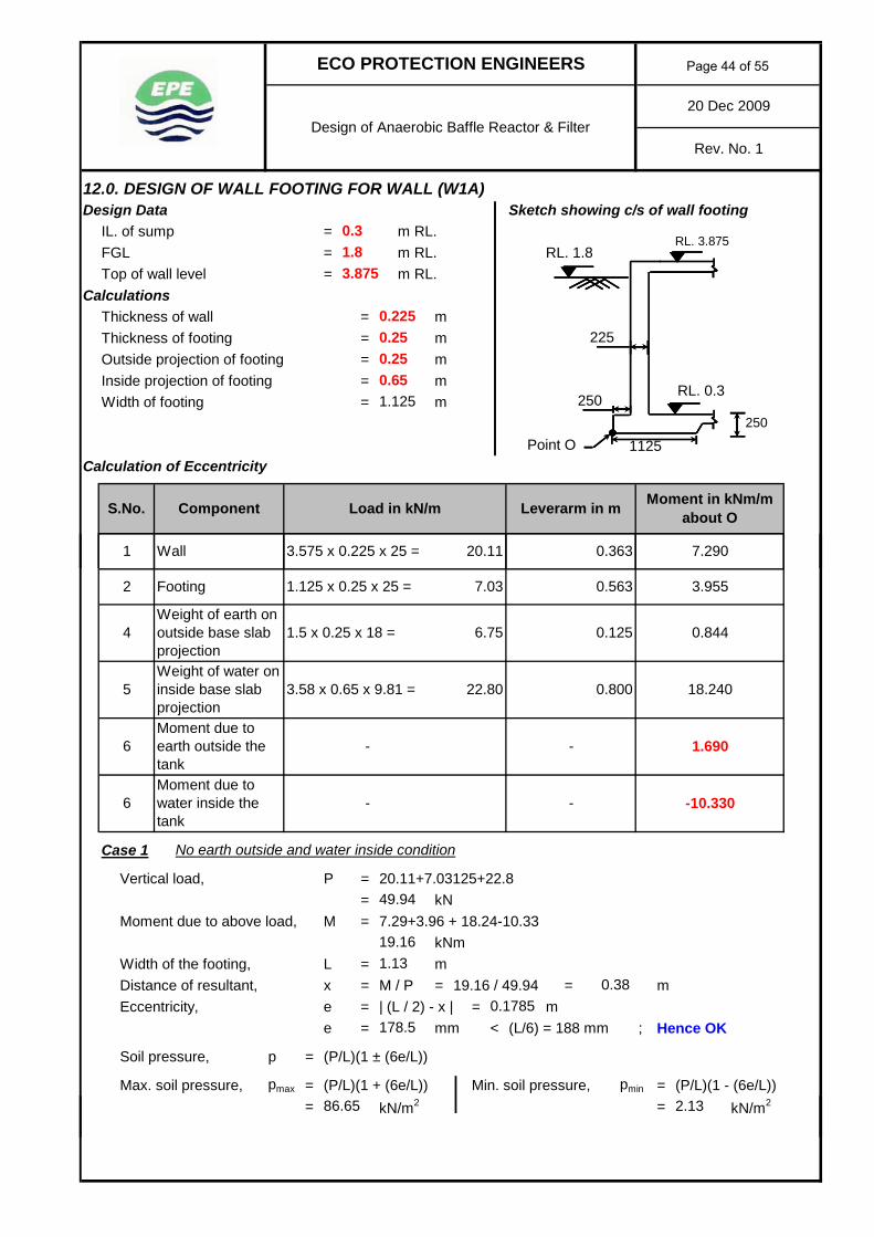
12.0. DESIGN OF WALL FOOTING FOR WALL (W1A)Design Data Sketch showing c/s of wall footing
IL. of sump = m RL.FGL = m RL. RL. 1.8Top of wall level = m RL.
CalculationsThickness of wall = mThickness of footing = mOutside projection of footing = mInside projection of footing = mWidth of footing = m
Point OCalculation of Eccentricity
20 Dec 2009
Rev. No. 1Design of Anaerobic Baffle Reactor & Filter
ECO PROTECTION ENGINEERS
RL. 3.875
0.65
Leverarm in m Moment in kNm/m about O
20.11
0.3
RL. 0.3
Load in kN/m
1.8
0.25
3.875
0.225
1.125
0.25
250250
1125
225
3.575 x 0.225 x 25 = 7.2900.3631 Wall
S.No. Component
Case 1 No earth outside and water inside condition
Vertical load, P = 20.11+7.03125+22.8= kN
Moment due to above load, M = 7.29+3.96 + 18.24-10.33kNm
Width of the footing, L = mDistance of resultant, x = M / P = 19.16 / 49.94 = mEccentricity, e = | (L / 2) - x | = m
e = mm < (L/6) = 188 mm ; Hence OK
Soil pressure, p = (P/L)(1 ± (6e/L))
Max. soil pressure, pmax = (P/L)(1 + (6e/L)) Min. soil pressure, pmin = (P/L)(1 - (6e/L))= kN/m2 = kN/m2
- 1.690
1.5 x 0.25 x 18 =
1.125 x 0.25 x 25 =
49.94
3.955
0.8446.75
0.563
-
3.58 x 0.65 x 9.81 =
-
0.1785
0.125
7.03
0.80022.80 18.240
86.65
1.13
178.5
19.16
Footing
Weight of water on inside base slab projectionMoment due to earth outside the tank
6
5
Weight of earth on outside base slab projection
6Moment due to water inside the tank
2
4
2.13
0.38
-10.330-
Page 44 of 55

20 Dec 2009
Rev. No. 1Design of Anaerobic Baffle Reactor & Filter
ECO PROTECTION ENGINEERS
kN/m2 kN/m2
kN/m2 kN/m2
Case 2 Earth outside and no water inside condition
Vertical load, P = 20.11+7.03125+6.75= kN
Moment due to above load, M = 7.29+3.96 + 0.84--1.69= kNm
Width of the footing, L = mDistance of the resultant, x = M / P = 13.78 / 33.89 = m
86.65
67.868
2.13
50.964
33.89
1.1313.78
0.41Eccentricity, e = | (L / 2) - x | = m
e = mm < (L/6) = 188 mm ; Hence OK
Soil pressure, p = (P/L)(1 ± (6e/L))
Max. soil pressure, pmax = (P/L)(1 + (6e/L)) Min. soil pressure, pmin = (P/L)(1 - (6e/L))= kN/m2 = kN/m2
kN/m2 kN/m2
kN/m2 kN/m2
Case 3 Earth outside and water inside condition
Vertical load, P = 20.11+7.03125+6.75+22.8kN
Moment due to above load, M = 7.29+3.96+0.84+18.24+1.69-10.33= kNm
Width of the footing, L = mDistance of the resultant, x = M / P = 21.69 / 56.69 = mEccentricity, e = | (L / 2) - x | = m
e = mm < (L/6) = 188 mm ; Hence OK
Soil pressure, p = (P/L)(1 ± (6e/L))
55.11
1.130.38
0.1795179.5
5.14
155.5
55.11
34.012
21.69
44.006
56.69
5.14
0.1555
Max. soil pressure, pmax = (P/L)(1 + (6e/L)) Min. soil pressure, pmin = (P/L)(1 - (6e/L))= kN/m2 = kN/m22.1598.63
Page 45 of 55

20 Dec 2009
Rev. No. 1Design of Anaerobic Baffle Reactor & Filter
ECO PROTECTION ENGINEERS
Net allowable bearing capacity= kN/m2
Gross allowable bearing pressure= 200 + (18 x 1.5)= kN/m2
kN/m2 kN/m2 Max. gross soil pressure= kN/m2 < kN/m2
; Hence OKkN/m2 kN/m2
Design of cantilever projection of footing Characteristic strength of materialDesign Data Grade of Concrete, fck = N/mm2
Thickness of footing, D = m Grade of Reinf.steel, fy = N/mm2
Projection of footing, l = m Cover to Reinf. steelEarth face = mm
CalculationsCase 1
Gross soil pressure at face of footing w 2 = kN/m2 w = 25 x 0 25 = kN/m250 964
227
40
2.15
57.894
0.65
98.63
0.25
77.19
25
6 25
415
98.63
200
227
Gross soil pressure at face of footing, w 2 = kN/m2 w = 25 x 0.25 = kN/m2
Gross soil pressure at edge of footing, w 1 = kN/m2
(w 2 - w 1) l2
= kNm kN/m2 kN/m2
Net BM for Design Mu = 3.89 - 1.32 = kNm
Case 2Gross soil pressure at face of footing, w 2 = kN/m2 w = 25 x 0.25 = kN/m2
Gross soil pressure at edge of footing, w 1 = kN/m2
(w 2 - w 1) l2
= kNm kN/m2 kN/m2
Net BM for Design Mu = 3.12 - 1.32 = kNm
Case 3Gross soil pressure at face of footing, w 2 = kN/m2 w = 25 x 0.25 = kN/m2
Gross soil pressure at edge of footing, w 1 = kN/m2
(w 2 - w 1) l2
= kNm kN/m2 kN/m2
1.8
4.38
2.15
+62
=w l 2
1.32
5.14
M2
w 1 l2
=
w 1 l2
34.012
kNm=
50.964
+6 2.1350.964
0.65
1.32=
2.13
3.12w l 2
6
2.57
6.25
5.142
=
M =BM at face of wall due to gross soil pressure,
= +
BM at face of wall due to gross soil pressure, M w l 2
2=
M
BM at face of wall due to gross soil pressure,
BM at face of wall due to gross soil pressure, M
BM at face of wall due to gross soil pressure,
2
w 1 l2
3.89
BM at face of wall due to gross soil pressure, M =
21.32 kNm
0.65
0.6557.894
57.894
34.012
kNm
2.15
6.25
6.25
Net BM for Design Mu = 4.38 - 1.32 = kNmDesign Bending Moment, Mu = kNmDepth required, dreq. = ((6 M)/(b σcbt)) where, σcbt = N/mm2
3.06
1.83.06
Page 46 of 55

20 Dec 2009
Rev. No. 1Design of Anaerobic Baffle Reactor & Filter
ECO PROTECTION ENGINEERS
= mm < mm ; Hence OK
let bar diameter = mm For Earth face, = N/mm2
Eff. Depth, d = mm j =Ast, req = M / (σst j d) = mm2 pt, min = % on both faceAst, min = mm2 = % on each face
Reinforcement detailsAst = mm2 at bottom ; Ast = mm2 at top
@ mm c/c at bottom transverse (Ast pro. = mm2 )
@ mm c/c at top transverse (Ast pro. = mm2 )
@ mm c/c (T & B) longitudinally (Ast pro. = mm2 ) Check for Shear
Critical section for shear is at a distance of d from the face of wallDistance, l 1 = l - d = m
Case 1 X1Pressure, w 1 = kN/m2 ; w 2 = kN/m2
Total shear at section X1-X1 = + (1/2) (w 2 - w 1) l 1
= kN / metre length
257.5 0.103
206σst 190
0.898
88
d
302
0.444
257.5
175
0.444
2.13 35.49
8 35
257.5
Provide Y 8 175
Provide Y 8 302
0.206
101 250
Provide Y 8 175
w 1 l 1
302
= kN / metre length
kN/m2 kN/m2
Case 2 X1Pressure, w 1 = kN/m2 ; w 2 = kN/m2
Total shear at section X1-X1 = + (1/2) (w 2 - w 1) l 1
= kN / metre length
kN/m2 kN/m2
Case 3 X1Pressure, w 1 = kN/m2 ; w 2 = kN/m2
Total shear at section X1-X1 = + (1/2) (w 2 - w 1) l 1
= kN / metre length
kN/m2 kN/m2
Design shear, Vu = kN / metre lengthShear strength of concrete, τc = N/mm2
Shear stress developed, τv = Vu / bd= N/mm2 < N/mm2 ; Hence OK
24.86 5.14
d 0.444
2.1335.49
2.15 40.23
w 1 l 1
6.66
5.14
8.35
24.86
2.15
0.444d
1.86390.05
w 1 l 1
9.4140.23
1.86399.41
Page 47 of 55
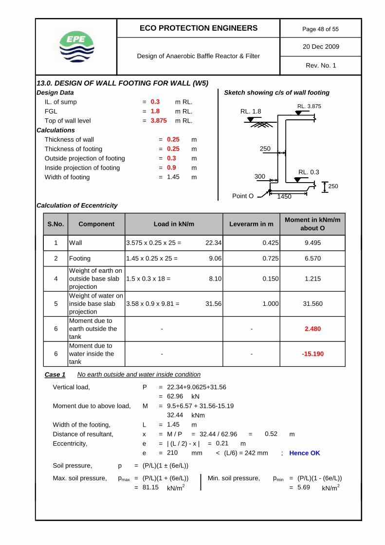
13.0. DESIGN OF WALL FOOTING FOR WALL (W5)Design Data Sketch showing c/s of wall footing
IL. of sump = m RL.FGL = m RL. RL. 1.8Top of wall level = m RL.
CalculationsThickness of wall = mThickness of footing = mOutside projection of footing = mInside projection of footing = mWidth of footing = m
Point OCalculation of Eccentricity
S.No. Component
1 Wall
250
3.575 x 0.25 x 25 = 9.4950.425
3.875
0.25
1.45
0.3
250300
1450
1.8
0.25
RL. 0.3
Load in kN/m
RL. 3.875
0.9
Leverarm in m Moment in kNm/m about O
22.34
0.3
20 Dec 2009
Rev. No. 1Design of Anaerobic Baffle Reactor & Filter
ECO PROTECTION ENGINEERS
Case 1 No earth outside and water inside condition
Vertical load, P = 22.34+9.0625+31.56= kN
Moment due to above load, M = 9.5+6.57 + 31.56-15.19kNm
Width of the footing, L = mDistance of resultant, x = M / P = 32.44 / 62.96 = mEccentricity, e = | (L / 2) - x | = m
e = mm < (L/6) = 242 mm ; Hence OK
Soil pressure, p = (P/L)(1 ± (6e/L))
Max. soil pressure, pmax = (P/L)(1 + (6e/L)) Min. soil pressure, pmin = (P/L)(1 - (6e/L))= kN/m2 = kN/m2
0.52
-15.190-
5.69
6Moment due to water inside the tank
2
4
6
5
Weight of earth on outside base slab projection
81.15
1.45
210
32.44
Footing
Weight of water on inside base slab projectionMoment due to earth outside the tank
9.06
1.00031.56 31.560
-
3.58 x 0.9 x 9.81 =
-
0.21
0.150
62.96
6.570
1.2158.10
0.725
- 2.480
1.5 x 0.3 x 18 =
1.45 x 0.25 x 25 =
Page 48 of 55

20 Dec 2009
Rev. No. 1Design of Anaerobic Baffle Reactor & Filter
ECO PROTECTION ENGINEERS
kN/m2 kN/m2
kN/m2 kN/m2
Case 2 Earth outside and no water inside condition
Vertical load, P = 22.34+9.0625+8.1= kN
Moment due to above load, M = 9.5+6.57 + 1.22--2.48= kNm
Width of the footing, L = mDistance of the resultant, x = M / P = 19.76 / 39.5 = m0.50
39.50
1.4519.76
52.527
81.15
65.538
5.69
Eccentricity, e = | (L / 2) - x | = me = mm < (L/6) = 242 mm ; Hence OK
Soil pressure, p = (P/L)(1 ± (6e/L))
Max. soil pressure, pmax = (P/L)(1 + (6e/L)) Min. soil pressure, pmin = (P/L)(1 - (6e/L))= kN/m2 = kN/m2
kN/m2 kN/m2
kN/m2 kN/m2
Case 3 Earth outside and water inside condition
Vertical load, P = 22.34+9.0625+8.1+31.56kN
Moment due to above load, M = 9.5+6.57+1.22+31.56+2.48-15.19= kNm
Width of the footing, L = mDistance of the resultant, x = M / P = 36.13 / 71.06 = mEccentricity, e = | (L / 2) - x | = m
e = mm < (L/6) = 242 mm ; Hence OK
Soil pressure, p = (P/L)(1 ± (6e/L))
1.88
0.225
36.13
42.106
71.06
225
52.6
33.361
1.8852.6
1.450.51
0.217217
Max. soil pressure, pmax = (P/L)(1 + (6e/L)) Min. soil pressure, pmin = (P/L)(1 - (6e/L))= kN/m2 = kN/m293.01 5
Page 49 of 55

20 Dec 2009
Rev. No. 1Design of Anaerobic Baffle Reactor & Filter
ECO PROTECTION ENGINEERS
Net allowable bearing capacity= kN/m2
Gross allowable bearing pressure= 200 + (18 x 1.5)= kN/m2
kN/m2 kN/m2 Max. gross soil pressure= kN/m2 < kN/m2
; Hence OKkN/m2 kN/m2
Design of cantilever projection of footing Characteristic strength of materialDesign Data Grade of Concrete, fck = N/mm2
Thickness of footing, D = m Grade of Reinf.steel, fy = N/mm2
Projection of footing, l = m Cover to Reinf. steelEarth face = mm
CalculationsCase 1
Gross soil pressure at face of footing w 2 = kN/m2 w = 25 x 0 25 = kN/m2
93.01
200
227
25
6 25
415
93.01
0.25
74.801
5
59.627
0.9
52 527
227
40
Gross soil pressure at face of footing, w 2 = kN/m2 w = 25 x 0.25 = kN/m2
Gross soil pressure at edge of footing, w 1 = kN/m2
(w 2 - w 1) l2
= kNm kN/m2 kN/m2
Net BM for Design Mu = 8.63 - 2.53 = kNm
Case 2Gross soil pressure at face of footing, w 2 = kN/m2 w = 25 x 0.25 = kN/m2
Gross soil pressure at edge of footing, w 1 = kN/m2
(w 2 - w 1) l2
= kNm kN/m2 kN/m2
Net BM for Design Mu = 5.01 - 2.53 = kNm
Case 3Gross soil pressure at face of footing, w 2 = kN/m2 w = 25 x 0.25 = kN/m2
Gross soil pressure at edge of footing, w 1 = kN/m2
(w 2 - w 1) l2
= kNm kN/m2 kN/m2
33.361
kNm
5
6.25
6.25
kNm
0.9
0.959.627
59.627
2.53
2
w 1 l2
8.63
BM at face of wall due to gross soil pressure, M =
2
BM at face of wall due to gross soil pressure,
BM at face of wall due to gross soil pressure, M
BM at face of wall due to gross soil pressure, +
BM at face of wall due to gross soil pressure, M w l 2
2=
M
=
M =BM at face of wall due to gross soil pressure,
=1.882
6.1
6.25
2.53=
5.69
5.01w l 2
6
52.527
+6 5.6952.527
0.9
1.88
M2
w 1 l2
=
w 1 l2
33.361
kNm= 2.53
2.48
9.4
5
+62
=w l 2
Net BM for Design Mu = 9.4 - 2.53 = kNmDesign Bending Moment, Mu = kNmDepth required, dreq. = ((6 M)/(b σcbt)) where, σcbt = N/mm21.8
6.876.87
Page 50 of 55

20 Dec 2009
Rev. No. 1Design of Anaerobic Baffle Reactor & Filter
ECO PROTECTION ENGINEERS
= mm < mm ; Hence OK
let bar diameter = mm For Earth face, = N/mm2
Eff. Depth, d = mm j =Ast, req = M / (σst j d) = mm2 pt, min = % on both faceAst, min = mm2 = % on each face
Reinforcement detailsAst = mm2 at bottom ; Ast = mm2 at top
@ mm c/c at bottom transverse (Ast pro. = mm2 )
@ mm c/c at top transverse (Ast pro. = mm2 )
@ mm c/c (T & B) longitudinally (Ast pro. = mm2 ) Check for Shear
Critical section for shear is at a distance of d from the face of wallDistance, l 1 = l - d = m
Case 1 X1Pressure, w 1 = kN/m2 ; w 2 = kN/m2
Total shear at section X1-X1 = + (1/2) (w 2 - w 1) l 1
= kN / metre length
Provide Y 8 175
w 1 l 1
302
302
0.206
151 250
257.5
Provide Y 8 175
Provide Y 8
0.694
5.69 41.81
16 48
175
d
302
0.694
257.5
257.5 0.103
206σst 190
0.898
197
= kN / metre length
kN/m2 kN/m2
Case 2 X1Pressure, w 1 = kN/m2 ; w 2 = kN/m2
Total shear at section X1-X1 = + (1/2) (w 2 - w 1) l 1
= kN / metre length
kN/m2 kN/m2
Case 3 X1Pressure, w 1 = kN/m2 ; w 2 = kN/m2
Total shear at section X1-X1 = + (1/2) (w 2 - w 1) l 1
= kN / metre length
kN/m2 kN/m2
Design shear, Vu = kN / metre lengthShear strength of concrete, τc = N/mm2
Shear stress developed, τv = Vu / bd= N/mm2 < N/mm2 ; Hence OK0.09
w 1 l 1
18.0947.12
1.863918.09
1.8639
5
0.694d47.12
w 1 l 1
9.73
1.88
16.48
26.16
5
1.88
d 0.694
5.6941.81
26.16
Page 51 of 55

14.0. DESIGN OF WALL FOOTING FOR WALL (W6)Design Data Sketch showing c/s of wall footing
IL. of sump = m RL.FGL = m RL. RL. 1.8Top of wall level = m RL.
CalculationsThickness of wall = mThickness of footing = mOutside projection of footing = mInside projection of footing = mWidth of footing = m
Point OCalculation of Eccentricity
S.No. Component
1 Wall
250
3.575 x 0.25 x 25 = 9.4950.425
3.875
0.25
1.45
0.3
250300
1450
1.8
0.25
RL. 0.3
Load in kN/m
RL. 3.875
0.9
Leverarm in m Moment in kNm/m about O
22.34
0.3
20 Dec 2009
Rev. No. 1Design of Anaerobic Baffle Reactor & Filter
ECO PROTECTION ENGINEERS
Case 1 No earth outside and water inside condition
Vertical load, P = 22.34+9.0625+31.56= kN
Moment due to above load, M = 9.5+6.57 + 31.56-16.4kNm
Width of the footing, L = mDistance of resultant, x = M / P = 31.23 / 62.96 = mEccentricity, e = | (L / 2) - x | = m
e = mm < (L/6) = 242 mm ; Hence OK
Soil pressure, p = (P/L)(1 ± (6e/L))
Max. soil pressure, pmax = (P/L)(1 + (6e/L)) Min. soil pressure, pmin = (P/L)(1 - (6e/L))= kN/m2 = kN/m2
0.50
-16.400-
2.28
6Moment due to water inside the tank
2
4
6
5
Weight of earth on outside base slab projection
84.57
1.45
229
31.23
Footing
Weight of water on inside base slab projectionMoment due to earth outside the tank
9.06
1.00031.56 31.560
-
3.58 x 0.9 x 9.81 =
-
0.229
0.150
62.96
6.570
1.2158.10
0.725
- 2.680
1.5 x 0.3 x 18 =
1.45 x 0.25 x 25 =
Page 52 of 55

20 Dec 2009
Rev. No. 1Design of Anaerobic Baffle Reactor & Filter
ECO PROTECTION ENGINEERS
kN/m2 kN/m2
kN/m2 kN/m2
Case 2 Earth outside and no water inside condition
Vertical load, P = 22.34+9.0625+8.1= kN
Moment due to above load, M = 9.5+6.57 + 1.22--2.68= kNm
Width of the footing, L = mDistance of the resultant, x = M / P = 19.96 / 39.5 = m0.51
39.50
1.4519.96
53.357
84.57
67.544
2.28
Eccentricity, e = | (L / 2) - x | = me = mm < (L/6) = 242 mm ; Hence OK
Soil pressure, p = (P/L)(1 ± (6e/L))
Max. soil pressure, pmax = (P/L)(1 + (6e/L)) Min. soil pressure, pmin = (P/L)(1 - (6e/L))= kN/m2 = kN/m2
kN/m2 kN/m2
kN/m2 kN/m2
Case 3 Earth outside and water inside condition
Vertical load, P = 22.34+9.0625+8.1+31.56kN
Moment due to above load, M = 9.5+6.57+1.22+31.56+2.68-16.4= kNm
Width of the footing, L = mDistance of the resultant, x = M / P = 35.12 / 71.06 = mEccentricity, e = | (L / 2) - x | = m
e = mm < (L/6) = 242 mm ; Hence OK
Soil pressure, p = (P/L)(1 ± (6e/L))
2.44
0.22
35.12
41.778
71.06
220
52.04
33.226
2.4452.04
1.450.49
0.231231
Max. soil pressure, pmax = (P/L)(1 + (6e/L)) Min. soil pressure, pmin = (P/L)(1 - (6e/L))= kN/m2 = kN/m295.85 2.16
Page 53 of 55

20 Dec 2009
Rev. No. 1Design of Anaerobic Baffle Reactor & Filter
ECO PROTECTION ENGINEERS
Net allowable bearing capacity= kN/m2
Gross allowable bearing pressure= 200 + (18 x 1.5)= kN/m2
kN/m2 kN/m2 Max. gross soil pressure= kN/m2 < kN/m2
; Hence OKkN/m2 kN/m2
Design of cantilever projection of footing Characteristic strength of materialDesign Data Grade of Concrete, fck = N/mm2
Thickness of footing, D = m Grade of Reinf.steel, fy = N/mm2
Projection of footing, l = m Cover to Reinf. steelEarth face = mm
CalculationsCase 1
Gross soil pressure at face of footing w 2 = kN/m2 w = 25 x 0 25 = kN/m2
95.85
200
227
25
6 25
415
95.85
0.25
76.466
2.16
60.312
0.9
53 357
227
40
Gross soil pressure at face of footing, w 2 = kN/m2 w = 25 x 0.25 = kN/m2
Gross soil pressure at edge of footing, w 1 = kN/m2
(w 2 - w 1) l2
= kNm kN/m2 kN/m2
Net BM for Design Mu = 7.82 - 2.53 = kNm
Case 2Gross soil pressure at face of footing, w 2 = kN/m2 w = 25 x 0.25 = kN/m2
Gross soil pressure at edge of footing, w 1 = kN/m2
(w 2 - w 1) l2
= kNm kN/m2 kN/m2
Net BM for Design Mu = 5.14 - 2.53 = kNm
Case 3Gross soil pressure at face of footing, w 2 = kN/m2 w = 25 x 0.25 = kN/m2
Gross soil pressure at edge of footing, w 1 = kN/m2
(w 2 - w 1) l2
= kNm kN/m2 kN/m2
33.226
kNm
2.16
6.25
6.25
kNm
0.9
0.960.312
60.312
2.53
2
w 1 l2
7.82
BM at face of wall due to gross soil pressure, M =
2
BM at face of wall due to gross soil pressure,
BM at face of wall due to gross soil pressure, M
BM at face of wall due to gross soil pressure, +
BM at face of wall due to gross soil pressure, M w l 2
2=
M
=
M =BM at face of wall due to gross soil pressure,
=2.442
5.29
6.25
2.53=
2.28
5.14w l 2
6
53.357
+6 2.2853.357
0.9
2.44
M2
w 1 l2
=
w 1 l2
33.226
kNm= 2.53
2.61
8.73
2.16
+62
=w l 2
Net BM for Design Mu = 8.73 - 2.53 = kNmDesign Bending Moment, Mu = kNmDepth required, dreq. = ((6 M)/(b σcbt)) where, σcbt = N/mm21.8
6.26.2
Page 54 of 55

20 Dec 2009
Rev. No. 1Design of Anaerobic Baffle Reactor & Filter
ECO PROTECTION ENGINEERS
= mm < mm ; Hence OK
let bar diameter = mm For Earth face, = N/mm2
Eff. Depth, d = mm j =Ast, req = M / (σst j d) = mm2 pt, min = % on both faceAst, min = mm2 = % on each face
Reinforcement detailsAst = mm2 at bottom ; Ast = mm2 at top
@ mm c/c at bottom transverse (Ast pro. = mm2 )
@ mm c/c at top transverse (Ast pro. = mm2 )
@ mm c/c (T & B) longitudinally (Ast pro. = mm2 ) Check for Shear
Critical section for shear is at a distance of d from the face of wallDistance, l 1 = l - d = m
Case 1 X1Pressure, w 1 = kN/m2 ; w 2 = kN/m2
Total shear at section X1-X1 = + (1/2) (w 2 - w 1) l 1
= kN / metre length
Provide Y 8 175
w 1 l 1
302
302
0.206
144 250
257.5
Provide Y 8 175
Provide Y 8
0.694
2.28 41.67
15 25
175
d
302
0.694
257.5
257.5 0.103
206σst 190
0.898
178
= kN / metre length
kN/m2 kN/m2
Case 2 X1Pressure, w 1 = kN/m2 ; w 2 = kN/m2
Total shear at section X1-X1 = + (1/2) (w 2 - w 1) l 1
= kN / metre length
kN/m2 kN/m2
Case 3 X1Pressure, w 1 = kN/m2 ; w 2 = kN/m2
Total shear at section X1-X1 = + (1/2) (w 2 - w 1) l 1
= kN / metre length
kN/m2 kN/m2
Design shear, Vu = kN / metre lengthShear strength of concrete, τc = N/mm2
Shear stress developed, τv = Vu / bd= N/mm2 < N/mm2 ; Hence OK0.08
w 1 l 1
17.0647
1.863917.06
1.8639
2.16
0.694d47
w 1 l 1
9.93
2.44
15.25
26.18
2.16
2.44
d 0.694
2.2841.67
26.18
Page 55 of 55


![NovoNail PPT1 [Autosaved] [Autosaved]](https://cdn.vdocuments.us/doc/165x107/587df8121a28abab7e8b62bb/novonail-ppt1-autosaved-autosaved.jpg)


![Mathematics of nyquist plot [autosaved] [autosaved]](https://cdn.vdocuments.us/doc/165x107/55a6a9751a28ab056b8b468d/mathematics-of-nyquist-plot-autosaved-autosaved.jpg)