DESIGN, MANUFACTURING AND TESTING OFINDUCTION FURNACE
A PROJECT REPORT
Submitted by
FRANCIS. T (103378044)
GIPSON PEREIRA (103378049)
MOHAMED ASHIQ.M (103378086)
MANIVANNAN.N (103378077)
in partial fulfillment for the award of the degree
of
BACHELOR OF TECHNOLOGY
In
MECHANICAL ENGINEERING
BHARATHIYAR COLLEGE OF ENGINEERING ANDTECHNOLOGY KARAIKAL
PONDICHERRY UNIVERSITY: PUDUCHERRY 605014
APRIL 2013
1
BHARATHIYAR COLLEGE OF ENGINEERING AND TECHNOLOGY
KARAIKAL
DEPARTMENT OF MECHANICAL ENGINEERING
BONAFIDE CERTIFICATE
Certified that this project report “DESIGN, MANUFACTURING AND TESTING OF INDUCTION FURNACE” is the bonafide work of
FRANCIS. T (103378044)GIPSON PEREIRA (103378049)MOHAMED ASHIQ.M (103378086)MANIVANNAN.N (103378077)
who carried out the project work under my supervision.
SIGNATURE SIGNATURE Prof .S.RAVICHANDRAN Mr. S . GUNABALAN HEAD OF THE DEPARTMENT SUPERVISOR
Mechanical DepartmentBharathiyar College of EngineeringAnd Technology, Karaikal
Submitted for the university examination held on..........................................
INTERNAL EXAMINER EXTERNAL EXAMINER
PONDICHERRY UNIVERSITY: PUDHUCHERRY APRIL 2013
2
Associate professor Mechanical DepartmentBharathiyar College of EngineeringAnd Technology, Karaikal
ACKNOWLEDGEMENT
We would like to acknowledge all the people who have contributed to a great extent towards the initialization, the development and success of our project.
Our sincere thanks go to Dr. Jayaraman, Principal, Bharathiyar College of Engineering & Technology, Karaikal for extending the college facilities for the successful completion of our project and for his kind patronage.
We also thank Prof .S.Ravichandran, Professor & Head of the Department, Department of Mechanical Engineering, Bharathiyar College of Engineering & Technology, Karaikal for extending the excellent laboratory facilities, ideas and encouragement towards our project.
We cordially thank Mr. S. Gunabalan, Associat Professor of Mechanical Department, Department of Mechanical Engineering, Bharathiyar College of Engineering & Technology for providing innovative ideas and expert guidance for the successful completion of our project.
3

4

5
ABSTRACT
Aluminum are the important structural material in aerospace and car industries, as
well as in some other areas. Their main characteristics are small specific weight, good
mechanical properties, good processing and resistance to corrosion. Based on great marketing
interest of Aluminum, the investigation of technological parameters of workout of Aluminum
on a laboratory and pilot-plant scale is carried out. In this project a part of results on design
and definition of melting, alloying and casting conditions of aluminum are presented. These
investigations involve alloying temperature, alloying time, amount of alloying elements, and
sequence of their adding and casting temperature on the chemical composition,
microstructure and mechanical properties are investigated.
6
INTRODUCTON
Metal melting is the process of producing a liquid metal of the required composition
at the required rate, and with required amount of superheat while incurring the minimal cost.
It is one of the most important foundry practices, as it decides the quality of the casting.
There are number of methods available for melting foundry alloys such as pit furnace, open
hearth furnace, rotary furnace, cupola furnace, etc. The choice of the furnace depends on
several factors, primary among them are the compositional range of the material to be melted,
the fuel or energy used to melt the charge, the degree of refining and control over the process
and type and size of the melting unit.
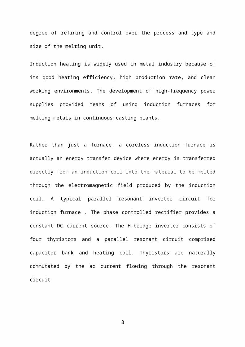
Induction heating is widely used in metal industry because of its good heating efficiency,
high production rate, and clean working environments. The development of high-frequency
power supplies provided means of using induction furnaces for melting metals in continuous
casting plants.
Rather than just a furnace, a coreless induction furnace is actually an energy transfer device
where energy is transferred directly from an induction coil into the material to be melted
through the electromagnetic field produced by the induction coil. A typical parallel resonant
inverter circuit for induction furnace . The phase controlled rectifier provides a constant DC
current source. The H-bridge inverter consists of four thyristors and a parallel resonant circuit
comprised capacitor bank and heating coil. Thyristors are naturally commutated by the ac
current flowing through the resonant circuit
7
FURNACE
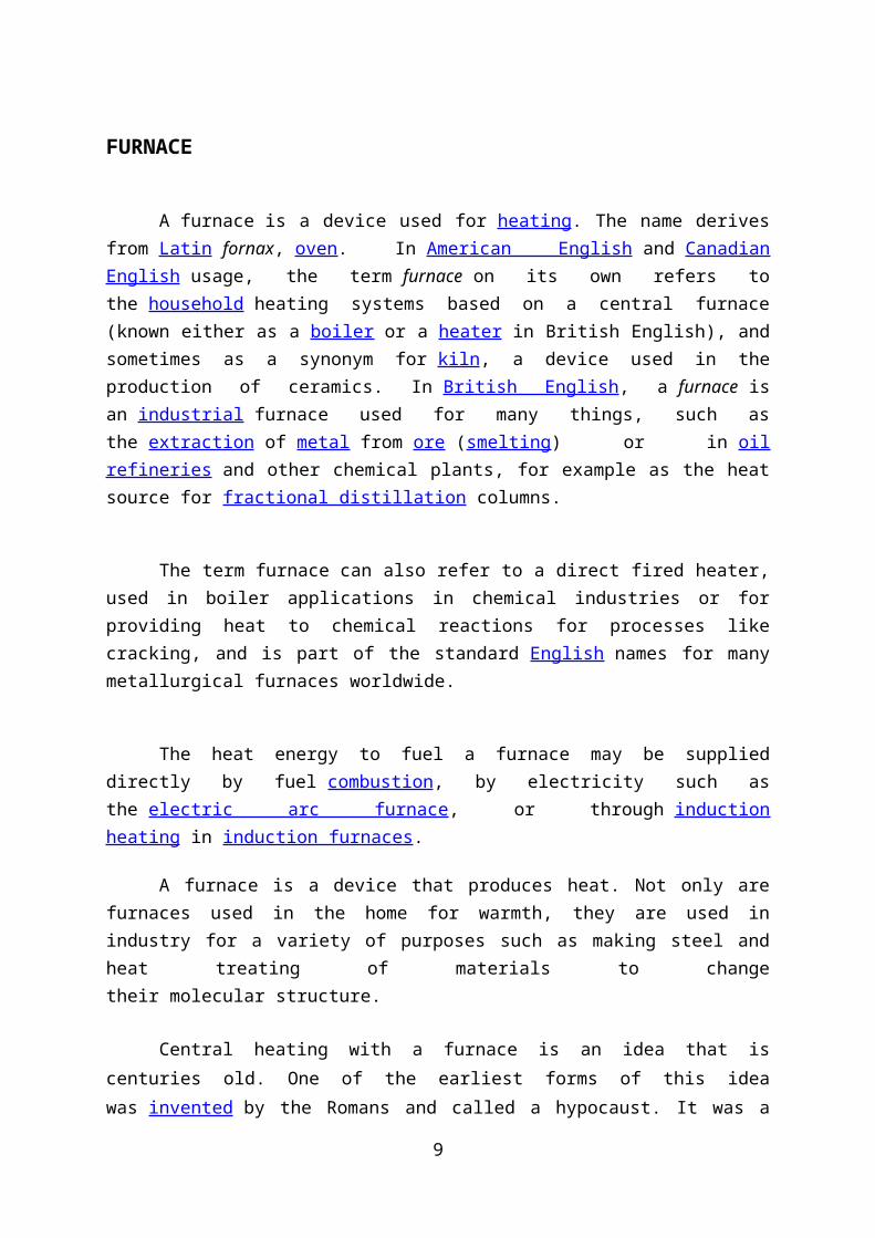
A furnace is a device used for heating. The name derives from Latin fornax, oven. In American English and Canadian English usage, the term furnace on its own refers to the household heating systems based on a central furnace (known either as a boiler or a heater in British English), and sometimes as a synonym for kiln, a device used in the production of ceramics. In British English, a furnace is an industrial furnace used for many things, such as the extraction of metal from ore (smelting) or in oil refineries and other chemical plants, for example as the heat source for fractional distillation columns.
The term furnace can also refer to a direct fired heater, used in boiler applications in chemical industries or for providing heat to chemical reactions for processes like cracking, and is part of the standard English names for many metallurgical furnaces worldwide.
The heat energy to fuel a furnace may be supplied directly by fuel combustion, by electricity such as the electric arc furnace, or through induction heating in induction furnaces.
A furnace is a device that produces heat. Not only are furnaces used in the home for warmth, they are used in industry for a variety of purposes such as making steel and heat treating of materials to change their molecular structure.
Central heating with a furnace is an idea that is centuries old. One of the earliest
forms of this idea was invented by the Romans and called a hypocaust. It was a form of
under-floor heating using a fire in one corner of a basement with the exhaust vented through
flues in the walls to chimneys. This form of heating could only be used in stone or brick
homes. It was also very dangerous because of the possibility of fire and suffocation.
Furnaces generate heat by burning fuel, but early furnaces burned wood. In the
seventeenth century, coal began to replace wood as a primary fuel. Coal was used until the
early 1940s when gas became the primary fuel. In the 1970s, electric furnaces started to
replace gas furnaces because of the energy crisis. Today, the gas furnace is still the most
popular form of home heating equipment.
Wood and coal burning furnaces required constant feeding to maintain warmth in the
home. From early morning to late at night, usually three to five times a day, fuel needed to be
put in the furnace. In addition, the waste from the ashes from the burnt wood or coal must be
removed and disposed.
8
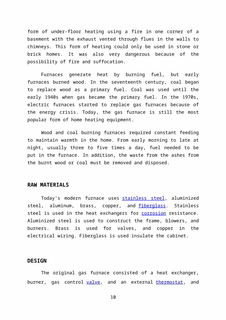
RAW MATERIALS
Today's modern furnace uses stainless steel, aluminized steel, aluminum, brass,
copper, and fiberglass. Stainless steel is used in the heat exchangers for corrosion resistance.
Aluminized steel is used to construct the frame, blowers, and burners. Brass is used for
valves, and copper in the electrical wiring. Fiberglass is used insulate the cabinet.
DESIGN
The original gas furnace consisted of a heat exchanger, burner, gas control valve, and
an external thermostat, and there was no blower. Natural convection or forced air flow was
used to circulate the air through large heating ducts and cold air returns to and from each
room. This system was very inefficient—allowing over half of the heated air to escape up the
chimney.
Today's gas furnace consists of a heat exchanger, secondary heat exchanger
(depending on efficiency rating), air circulation blower, flue draft blower, gas control valve,
burners, pilot light or spark ignition, electronic control circuitry, and an external thermostat.
The modern furnace is highly efficient—80-90%, allowing only 10-20% of the heated air to
escape up the chimney.
When heat is requested from the thermostat, the burners light and throws heat into the
primary heat exchanger. The heated air then flows through the secondary heat exchanger
(90% efficient furnace only) to the exhaust flue and chimney. The average furnace has three
heat exchangers each producing 25,000 BTUs for a total of 75,000 BTUs. A flue draft blower
is placed in the exhaust flue to supercharge the burners and increase efficiency. The heat
exchangers perform two functions: transfer heated air from the burners to the home and allow
dangerous exhaust
9
THE MANUFACTURING PROCESS1. The primary heat exchanger is formed from two separate pieces of 409
stainless steel sheet. Each half is formed into shape by a 400 ton hydraulic press. The two halves are then fused together by a 25 ton hydraulic press.
2. The secondary heat exchanger is formed from 29-4°C stainless steel tubing and fins. The fins are welded to the tubing to form a radiator type configuration.
3. The primary heat exchanger is crimped to the secondary heat exchanger through a transition box. The flue draft blower is attached to the secondary heat exchanger.
4. The burners are constructed of aluminized steel and arrive at the plant preformed. They are then attached to a plate on the input side of the primary heat exchanger. There is one burner for each heat exchanger in the furnace.
5. The vendor supplied gas control valve is mounted to the heat exchanger and burner assembly. It is connected to the burner through a pipe.
6. The air circulation blower housing is formed through the same hydraulic press formation as the primary heat exchanger. The vendor supplied motor and squirrel cage rotor are connected and attached to the blower housing with brackets.
7. A plate is then attached for mounting the blower assembly to the heat exchanger assembly. Another mounting plate containing the vendor supplied furnace control circuitry and transformer are attached to the blower housing.
8. The air circulation blower assembly is then mounted to the heat exchanger assembly with screws and nuts.
9. The cabinet consists of two doors and the cabinet housing. The cabinet housing is supplied as a flat pre-painted sheet of steel and placed in a hydraulic press to form a three sided configuration. Sheets of fiberglass insulation are glued to the sides of the cabinet.
10. The cabinet is installed around the furnace assembly and secured with screws and nuts. The doors are installed on the front of the cabinet assembly. The completed assembly is boxed and prepared for shipment.
10
QUALITY CONTROL
Each completed furnace undergoes an extensive series of tests. Checks for proper
operation of the flue draft and air circulation blowers are performed. The gas valve is checked
for proper operation. The heat output of the furnace in BTUs is measured. A dielectric test is
performed for shorts.
By products/Waste
Scrap metal from cutting and forming operations are collected and sent to recycling
plants for reclamation. Any excess piping is either reused or discarded. Defective steel sheets
can be sent back tot he manufacturer and reformed, depending on the extent of the damage.
The majority of the components of the furnace are able to be recycled.
Furnaces can also be classified according to the molten metal ;
1. Gray Cast Iron
Cupola
Air furnace
Rotary furnace
Electric arc furnace
2. Steel
Open hearth furnace.
Electric furnace.
Arc furnace
High frequency induction furnace
Converter
3. Non-ferrous metals
11
Crucible furnaces (Al ,Cu)
Pit type
Tilting type
Non-tilting or bale out type
Electric resistance type (CU)
Pot furnaces (fuel fired) (Mg & Al)
Stationary
Tilting
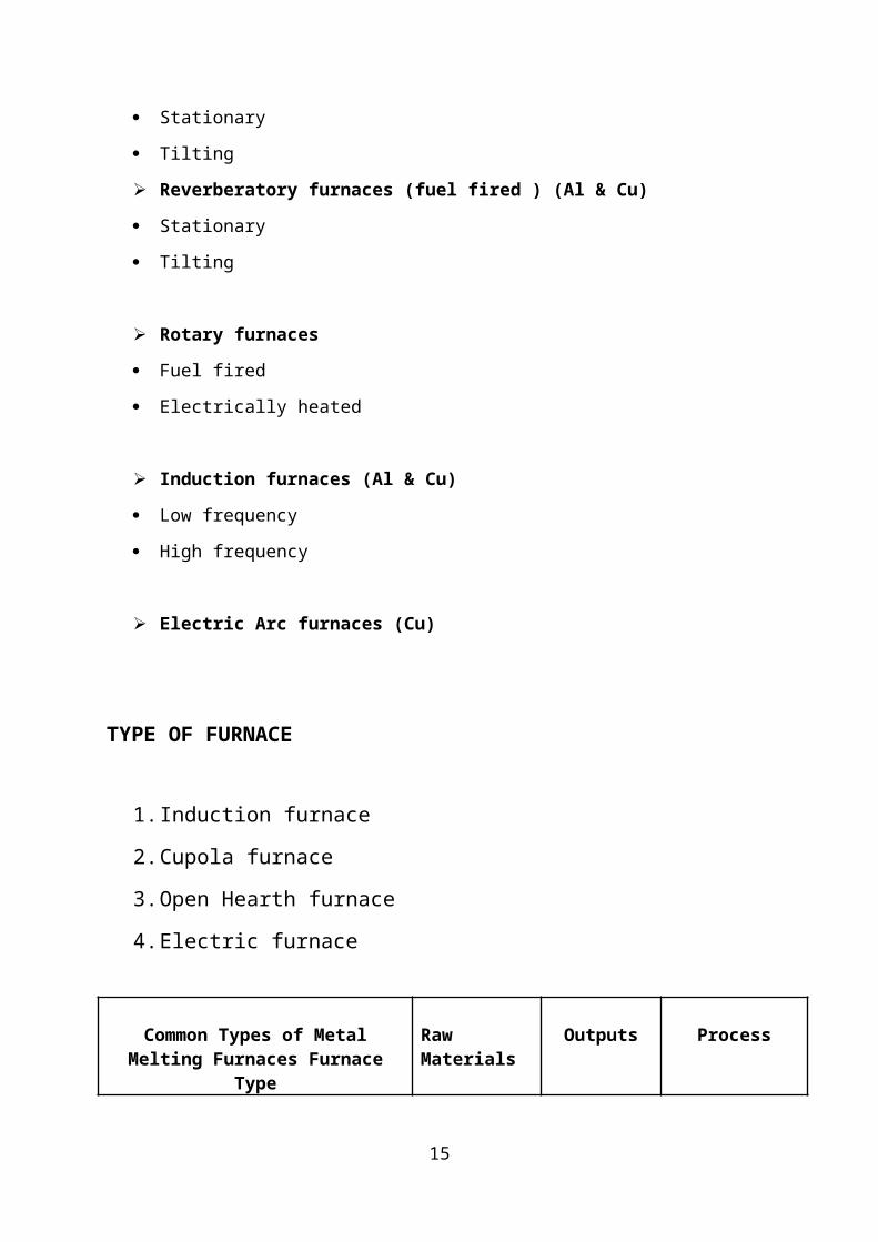
Reverberatory furnaces (fuel fired ) (Al & Cu)
Stationary
Tilting
Rotary furnaces
Fuel fired
Electrically heated
Induction furnaces (Al & Cu)
Low frequency
High frequency
Electric Arc furnaces (Cu)
TYPE OF FURNACE
1. Induction furnace
2. Cupola furnace
3. Open Hearth furnace
4. Electric furnace
12
Common Types of Metal Melting Furnaces Furnace Type
Raw Materials Outputs Process
Induction Furnace Scrap iron or non-ferrous metals
Molten iron or non-ferrous metals
Induction furnaces are the most common type used by both ferrous and non-ferrous foundries. Copper coils heat the metal using alternating currents. The flux reacts with impurities.
Cupola FurnaceIron ore, scrap iron, lime, coke
Molten iron
Alternative layers of metal and coke are fed into the top of the furnace. The metal is melted by the hot gases from the coke combustion. Impurities react with the lime and are separated.
Open Hearth Non-ferrous metals, flux
Molten non-ferrous metals
Reverberatory furnaces melt
metals in batches using a pot-shaped crucible that holds the metal over an electric heater or fuel-free burner.
The flux reacts with impurities
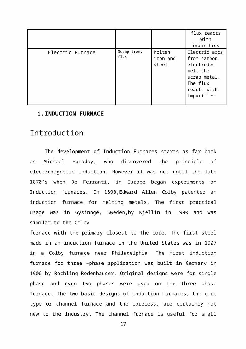
Electric Furnace Scrap iron, flux Molten iron and steel
Electric arcs from carbon electrodes melt the scrap metal. The flux reacts with impurities.
13

1. INDUCTION FURNACE
Introduction
The development of Induction Furnaces starts as far back as Michael Faraday, who
discovered the principle of electromagnetic induction. However it was not until the late
1870’s when De Ferranti, in Europe began experiments on Induction furnaces. In
1890,Edward Allen Colby patented an induction furnace for melting metals. The first
practical usage was in Gysinnge, Sweden,by Kjellin in 1900 and was similar to the Colby
furnace with the primary closest to the core. The first steel made in an induction furnace in
the United States was in 1907 in a Colby furnace near Philadelphia. The first induction
furnace for three –phase application was built in Germany in 1906 by Rochling-Rodenhauser.
Original designs were for single phase and even two phases were used on the three phase
furnace. The two basic designs of induction furnaces, the core type or channel furnace and
the coreless, are certainly not new to the industry. The channel furnace is useful for small
foundries with special requirements for large castings, especially if off-shift melting is
practiced. It is widely used for duplexing operations and installations where production
requirements demand a safe cushion of readily available molten metal. The coreless induction
furnace is used when a quick melt of one alloy is desirable, or it is necessary to vary alloys
frequently. The coreless furnace may be completely emptied and restarted easily, makes it
perfect for one-shift operations. Induction furnaces have increased in capacity to where
modern high-power-density induction furnaces are competing successfully with cupola
melting. There are fewer chemical reactions to manage in induction furnaces than in cupola
furnaces, making it easier to achieve melt composition. However, induction melting is
more sensitive to quality of charge materials when compared to cupola or electric arc furnace,
limiting the types of scrap that can be melted. The inherent induction stirring provides
excellent metal homogeneity. Induction melting produces a fraction of the fumes that result
from melting in an electric arc furnace (heavy metal fumes and particulate emissions) or
cupola (wide range of undesirable gaseous and particulate emissions as a result of
the less restrictive charge materials).
A new generation of industrial induction melting furnaces has been developed during the last
25 years. The development of flexible, constant power-tracking, medium-frequency induction
power supplies has resulted in the widespread use of the batch melting methods in modern
14
foundries. These power units incorporate heavy duty silicon-controlled rectifiers that are able
to generate both the frequency and the amperage needed for batch melting and are able to
achieve electrical efficiency levels exceeding 97%, a substantial improvement over the
85% efficiency typical of induction power supplies of the 1970s. The new designs allow
maximum utilization of furnace power throughout the melting cycle with good control of
stirring .Some of the largest commercial units are capable of melting at nearly 60 tons per
hour and small furnaces with very high power densities of 700 to 1,000 kWh/ton can now
melt a cold charge in 30 to 35 minutes.
INDUCTION HEATING:
Induction heating is a form of non-contact heating for conductive materials.
The principle of induction heating is mainly based on two well-known physical phenomena:
1. Electromagnetic induction
2. The Joule effect
1) ELECTROMAGNETIC INDUCTION
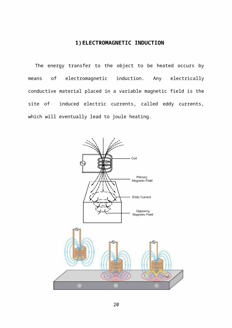
The energy transfer to the object to be heated occurs by means of electromagnetic
induction. Any electrically conductive material placed in a variable magnetic field is the site
of induced electric currents, called eddy currents, which will eventually lead to joule heating.
15

16
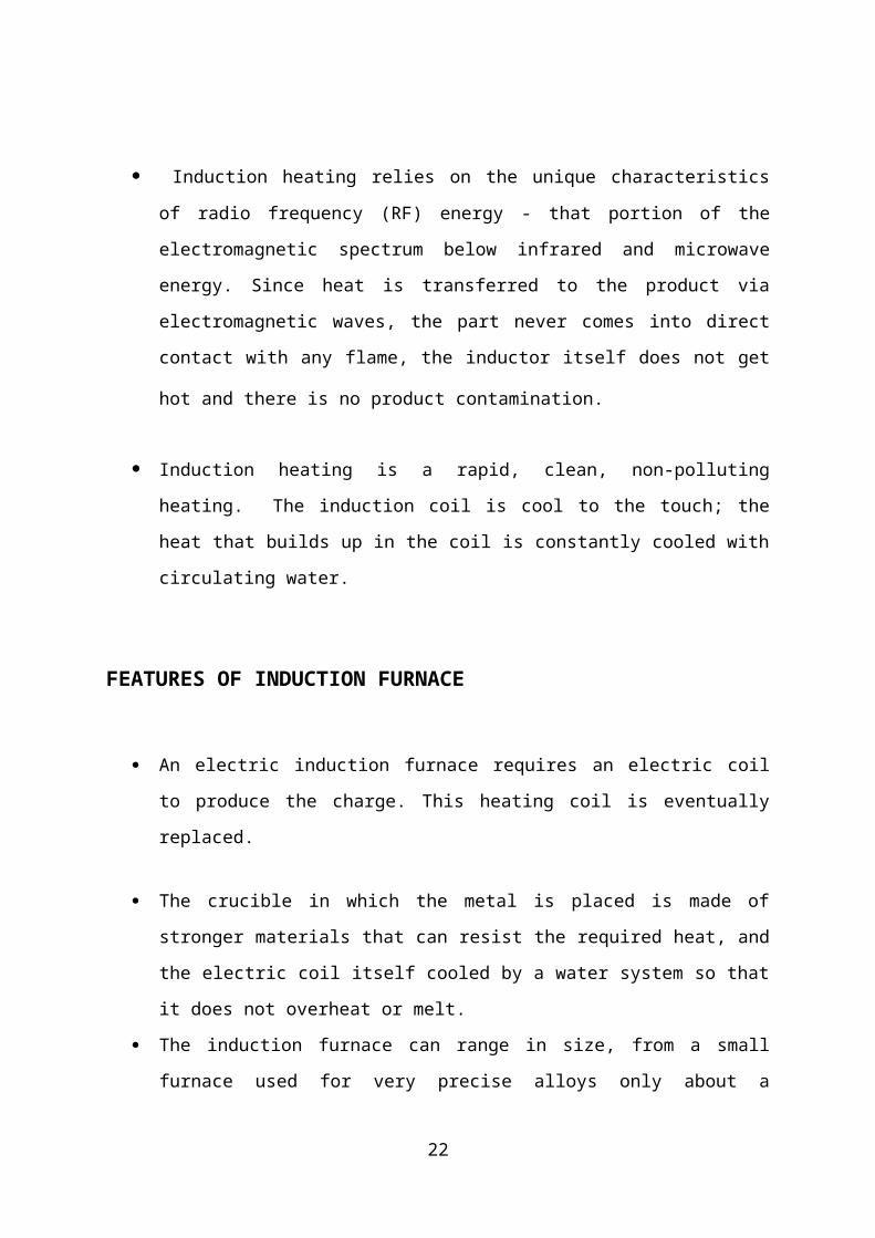
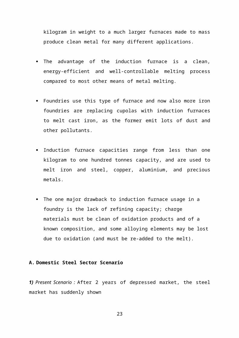
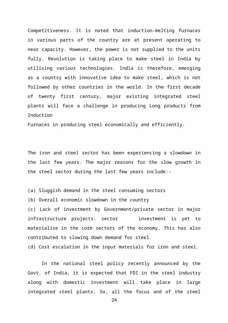
2) JOULE HEATING
Joule heating, also known as osmic heating and resistive heating, is the process by which the
passage of an electric current through a conductor releases heat.
The heat produced is proportional to the square of the current multiplied by the electrical
resistance of the wire.
Induction heating relies on the unique characteristics of radio frequency (RF) energy
- that portion of the electromagnetic spectrum below infrared and microwave energy.
Since heat is transferred to the product via electromagnetic waves, the part never
comes into direct contact with any flame, the inductor itself does not get hot and there
is no product contamination.
Induction heating is a rapid, clean, non-polluting heating. The induction coil is cool
to the touch; the heat that builds up in the coil is constantly cooled with circulating
water.
FEATURES OF INDUCTION FURNACE
An electric induction furnace requires an electric coil to produce the charge. This
heating coil is eventually replaced.
The crucible in which the metal is placed is made of stronger materials that can resist
the required heat, and the electric coil itself cooled by a water system so that it does
not overheat or melt.
17
The induction furnace can range in size, from a small furnace used for very precise
alloys only about a kilogram in weight to a much larger furnaces made to mass
produce clean metal for many different applications.
The advantage of the induction furnace is a clean, energy-efficient and well-
controllable melting process compared to most other means of metal melting.
Foundries use this type of furnace and now also more iron foundries are replacing
cupolas with induction furnaces to melt cast iron, as the former emit lots of dust and
other pollutants.
Induction furnace capacities range from less than one kilogram to one hundred tonnes
capacity, and are used to melt iron and steel, copper, aluminium, and precious metals.
The one major drawback to induction furnace usage in a foundry is the lack of
refining capacity; charge materials must be clean of oxidation products and of a
known composition, and some alloying elements may be lost due to oxidation (and
must be re-added to the melt).
A. Domestic Steel Sector Scenario
1) Present Scenario : After 2 years of depressed market, the steel market has suddenly shown
Competitiveness. It is noted that induction-melting furnaces in various parts of the country
are at present operating to near capacity. However, the power is not supplied to the units
fully. Revolution is taking place to make steel in India by utilising various technologies. India
is therefore, emerging as a country with innovative idea to make steel, which is not followed
by other countries in the world. In the first decade of twenty first century, major existing
integrated steel plants will face a challenge in producing Long products from Induction
Furnaces in producing steel economically and efficiently.
The iron and steel sector has been experiencing a slowdown in the last few years. The major
reasons for the slow growth in the steel sector during the last few years include:-
18
(a) Sluggish demand in the steel consuming sectors
(b) Overall economic slowdown in the country
(c) Lack of investment by Government/private sector in major infrastructure projects. sector
investment is yet to materialise in the core sectors of the economy. This has also contributed
to slowing down demand for steel.
(d) Cost escalation in the input materials for iron and steel.
In the national steel policy recently announced by the Govt. of India, it is expected
that FDI in the steel industry along with domestic investment will take place in large
integrated steel plants. So, all the focus and of the steel policy is on the Primary Steel Sector
while completely ignoring the Secondary Steel Sector.
Induction melting furnaces in India were first installed to make stainless steel from
imported SS Scrap. Butin years 81-82 some entrepreneurs, who were having small size
induction furnaces making stainless steel, experimented in making mild steel from steel
melting scrap, they succeeded. More firms in northern India produced steel (Pencil Ingots) by
using 500 kg to 1 tonne induction furnaces. The power consumption was found to be about
700 kWh/tonne, which was nearly 100 units less than EAFs. Bigger size Induction furnaces
were then installed first in North India and then in other states of India. By 1985-86, the
technology of making mild steel by Induction Furnace route was mastered by Indian
Technicians. Induction furnace manufacturers saw the potential and started manufacturing
bigger size/capacity furnaces. By 1988-89 period 3 tonne per charge induction furnaces were
installed (became standard) all over India. The chemistry of melt was adjusted by adding mill
scale, if opening carbon of bath was more. Good quality of steel melting scrap was used. In
1991-92, the Government license and control on steel making and rolling was removed. Then
more induction furnaces were installed all over India. The use of sponge iron made it possible
to adjust chemistry of melt. Thus good quality of Mild Steel pencil ingots are being produced
with no tramp elements.
2) Ferrous Scrap: The word “Ferrous” comes from the Latin word “Ferrum”. Most people
associate scrap with waste or rubbish. However, our Industry prefers to refer to ourselves as
“Recyclers”, who play a very important role, in not only feeding the Steel Industry but also
protecting the environment by converting waste into wealth for society.
19
Indian Steel Mills mainly import Shredded or Heavy Melting grades only. HMS is nearly
65% of the imports.
3) Global Requirement For Scrap: With global steel production at 1 billion tonne mark,
merchant scrap requirement is estimated in the current year at 318 million tonnes. By the year
2010, requirement for merchant scrap is likely to go up to 388 million tonnes. As the GDP
grows in developing countries, the generation of merchant scrap will increase and additional
processing capacities and scrap yards will have to be installed to meet the demand for quality
scrap needed for the increasing steel demand.
INDUCTION ELECTRICAL SYSTEM CONFIGURATION:
Induction furnaces require two separate electrical systems: one for the cooling system,
furnace tilting and instrumentation, and the other for the induction coil power. A line to the
plant’s power distribution panel typically furnishes power for the pumps in the induction coil
cooling system, the hydraulic furnace tilting mechanism, and instrumentation and control
systems. Electricity for the induction coils is furnished from a three-phase, high voltage, high
amperage utility line. The complexity of the power supply connected to the induction coils
varies with the type of furnace and its use.
A channel furnace that holds and pours liquefied metal can operate efficiently using
mains frequency provided by the local utility. By contrast, most coreless furnaces for melting
require a medium to high frequency power supply. Raising the frequency of the alternating
current flowing through the induction coils increases the amount of power that can be applied
to a given size furnace. This, in turn, means faster melting. A 10 ton coreless furnace
operating at 60 Hz can melt its capacity in two hours. At 275 Hz, the same furnace can melt
the full 10 ton charge in 26 minutes, or four times faster. An added advantage of higher
frequency operation is that furnaces can be started using less bulky scrap and can be emptied
completely between heats. The transformers, inverters and capacitors needed to “tune” the
frequency required for high-efficiency induction furnaces can pose a serious electrical hazard.
For this reason, furnace power supplies are housed in key-locked steel enclosures, equipped
with safety interlocks.
20
CONSTRUCTION AND WORKING
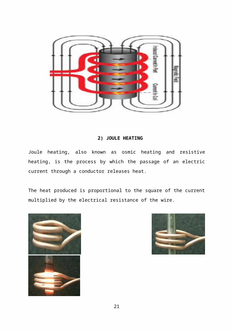
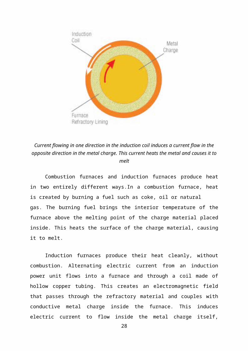
Current flowing in one direction in the induction coil induces a current flow in the opposite direction in the metal charge. This current heats the metal and causes it to melt
Combustion furnaces and induction furnaces produce heat in two entirely different
ways.In a combustion furnace, heat is created by burning a fuel such as coke, oil or natural
gas. The burning fuel brings the interior temperature of the furnace above the melting point of
the charge material placed inside. This heats the surface of the charge material, causing it to
melt.
Induction furnaces produce their heat cleanly, without combustion. Alternating
electric current from an induction power unit flows into a furnace and through a coil made of
hollow copper tubing. This creates an electromagnetic field that passes through the refractory
material and couples with conductive metal charge inside the furnace. This induces electric
current to flow inside the metal charge itself, producing heat that rapidly causes the metal to
melt. Although some furnace surfaces may become hot enough to present a burn hazard, with
induction, you heat the charge directly, not the furnace.
21
Induction Electrical System Configurations:
Induction furnaces require two separate electrical systems: one for the cooling system,
furnace tilting and instrumentation, and the other for the induction coil power. A line to the
plant’s power distribution panel typically furnishes power for the pumps in the induction coil
cooling system, the hydraulic furnace tilting mechanism, and instrumentation and control
systems. Electricity for the induction coils is furnished from a three-phase, high voltage, high
amperage utility line. The complexity of the power supply connected to the induction coils
varies with the type of furnace and its use.
A channel furnace that holds and pours liquefied metal can operate efficiently using
mains frequency provided by the local utility. By contrast, most coreless furnaces for melting
require a medium to high frequency power supply. Raising the frequency of the alternating
current flowing through the induction coils increases the amount of power that can be applied
to a given size furnace. This, in turn, means faster melting. A 10 ton coreless furnace
operating at 60 Hz can melt its capacity in two hours. At 275 Hz, the same furnace can melt
the full 10 ton charge in 26 minutes, or four times faster. An added advantage of higher
frequency operation is that furnaces can be started using less bulky scrap and can be emptied
completely between heats. The transformers, inverters and capacitors needed to “tune” the
frequency required for high-efficiency induction furnaces can pose a serious electrical hazard.
For this reason, furnace power supplies are housed in key-locked steel enclosures, equipped
with safety interlocks.
A. Safety Implications:
Typically, the induction coil power supply and the other furnace systems are energized
from multiple electric services. This means that foundry workers cannot assume that the
power to the furnace coil has stopped because service has been interrupted to the furnace’s
cooling system or hydraulic pumps. Review the lock out/tag out section provided in this
safety guide.
B. Input And Output Parameters Of The Induction Furnaces:
In order to study the prevailing practices in steel plants using Induction Furnaces, the
following parameters have been identified as
22
1) Raw Material: Induction Furnaces are using Steel melting scrap, Sponge Iron & Pig
Iron/Cast Irons. On an average the ratio of these items is 40% sponge Iron + 10% Cast Irons
or Pig Iron. The technology of melting these input materials varies according to the
availability of raw materials and location of the plant and inputs of sponge iron consumed is
as high as 85 % as charge mix on bigger furnaces.
2) Power Supply: An A.C.current from the transformer is fed to the rectifier of the furnaces
electronic circuit. This converts A.C. to D.C, voltage is smoothed out by a D.C. choke, and
then fed to the inverted section of the furnace. Here the D.C is converted to a high frequency
A.C. current and this is fed to the coil.
3) Refractory Lining: The material used for lining is crushed quarts. This is a high purity
silica material. The linings are of two types, acidic lining and basic lining.
4) Water: The cooling system is a through-one-way- flow system with the tubular copper
coils connected to water source through flexible rubber hoses. The inlet is from the top while
the outlet is at the bottom. The cooling process is important because the circuit of the furnace
appears resistive, and the real power is not only consumed in the charged material but also in
the resistance of the coil. This coil loss as well as the loss of heat conducted from the charge
through the refractory crucible requires the coil to be cooled with water as the cooling
medium to prevent undue temperature rise of the copper coils.
5) Molten Metal : The molten metal is the desired output of the Induction furnace. The
quantity depends upon the capacity of the furnace, and the quality depends upon the raw
material and alloy composition. The tapping temperature depends upon the type of steel, as
well as the distance of end use of the molten metal.
6) Waste Heat: The surface of the molten metal bath is exposed to atmosphere. This results in
the major thermal energy loss through radiation. The Coils of furnace are water cooled this
also results in heat loss.
23
7) Slag : During the operation of electric induction melting furnaces, non metallics are
produced from the various sources described earlier. Depending on the specific process being
used and the type of iron or steel being melted, the composition of the slag will vary.
8) Slag Composition: The composition of furnace and ladle slags is often very complex. The
slags that form in electric furnace melting are the results of complex reactions between silica
(adhering sand on casting returns or dirt), iron oxide from steel scrap, other oxidation by
products from melting, and reactions with refractory linings. The resulting slag will thus
consist of a complex liquid phase of oxides of iron, manganese, magnesium and silicon,
silicates and sulphides plus a host of other compounds, which may include alumina, calcium
oxides and sulphides, rare earth oxides and sulphides and spinel’s and fosterites.
ADVANTAGES OF INDUCTION FURNACE:
Induction furnaces offer certain advantages over other furnace systems. They include:
Higher Yield. The absence of combustion sources reduces oxidation losses that can be
significant in production economics.
Faster Start-up. Full power from the power supply is available, instantaneously, thus
reducing the time to reach working temperature. Cold charge-to-tap times of one to two hours
are common.
Flexibility. No molten metal is necessary to start medium frequency coreless induction
melting equipment. This facilitates repeated cold starting and frequent alloy changes.
Natural Stirring. Medium frequency units can give a strong stirring action resulting in a
homogeneous melt.
Cleaner Melting. No by-products of combustion means a cleaner melting environment and
no associated products of combustion pollution control systems.
Compact Installation. High melting rates can be obtained from small furnaces.
24
Reduced Refractory. The compact size in relation to melting rate means induction furnaces
require much less refractory than fuel-fired units
Better Working Environment. Induction furnaces are much quieter than gas furnaces, arc
furnaces, or cupolas. No combustion gas is present and waste heat is minimized.
Energy Conservation. Overall energy efficiency in induction melting ranges
from 55 to 75 percent, and is significantly better than combustion processes.
DISADVANTAGES OF INDUCTION FURNACE
1. Refining in Induction Furnace is not as intensive or effective as in Electric Arc Furnace
(EAF).
2. Life of Refractory lining is low as compared to EAF.
3. Removal of S & P is limited, so selection of charges with less impurity is required.
TYPES OF INDUCTION FURNACE
CORELESS INDUCTION FURNACE
CHANNEL INDUCTION FURNACE
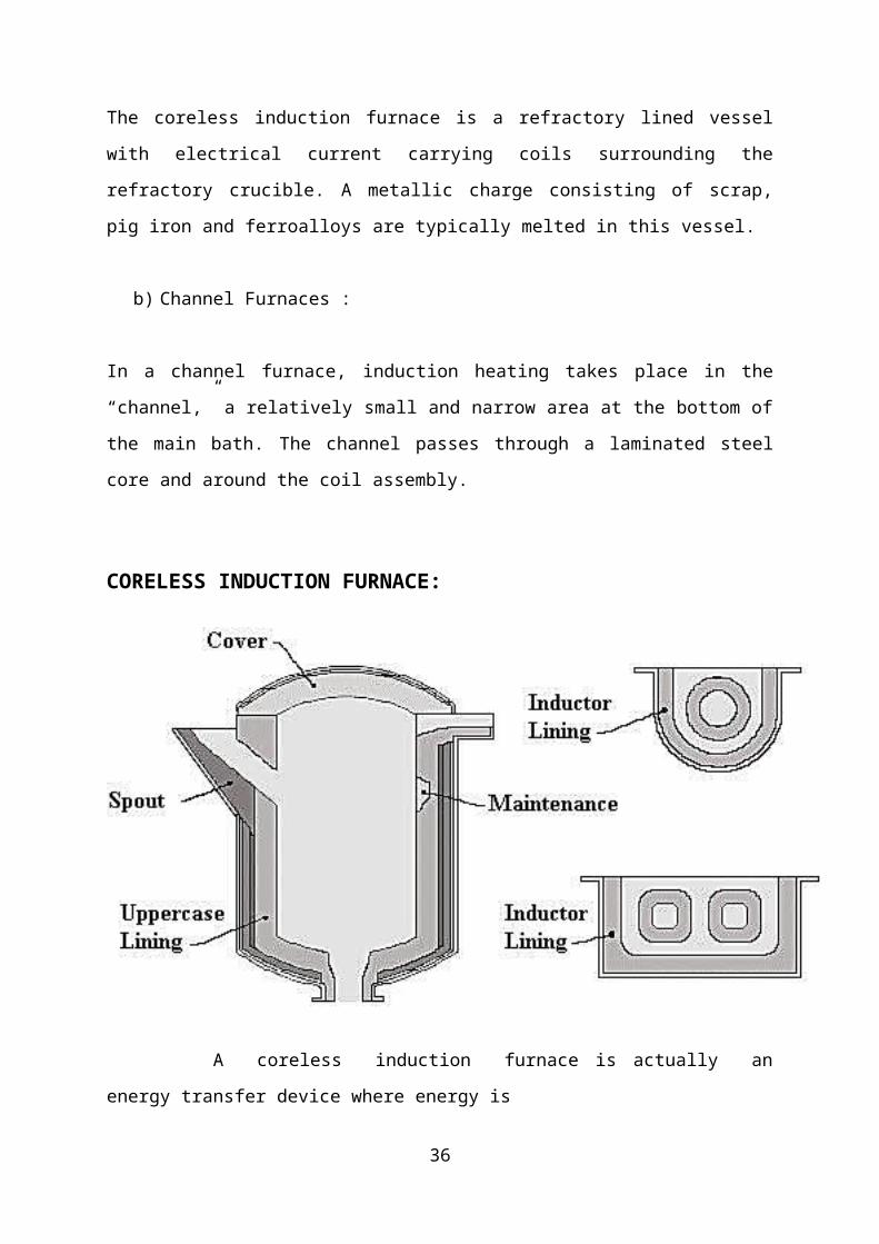
a) Coreless Induction Furnaces:
The coreless induction furnace is a refractory lined vessel with electrical current carrying
coils surrounding the refractory crucible. A metallic charge consisting of scrap, pig iron and
ferroalloys are typically melted in this vessel.
b) Channel Furnaces :
25

In a channel furnace, induction heating takes place in the “channel,” a relatively small and
narrow area at the bottom of the main bath. The channel passes through a laminated steel core
and around the coil assembly.
CORELESS INDUCTION FURNACE:
A coreless induction furnace is actually an energy transfer device where energy is
transferred directly from an induction coil into the material to be melted through the
electromagnetic field produced by the induction coil.
The coreless induction furnace consists basically of a crucible, inductor coil, shell,
cooling system and tilting mechanism. The crucible is formed from refractory material,
which the furnace coil is lined with. This crucible holds the charge material and subsequently
the melt. The choice of refractory material depends on the type of charge, i.e. acidic, basic or
neutral. The durability of the crucible depends on the grain size, ramming technique, charge
analysis and rate of heating and cooling the furnace .
Principles are:
26
The principle of induction heating is based on the following two laws:
1. Electromagnetic induction
2. The joule effect
The high frequency induction furnaces use the heat produced by eddy currents generated
by a high frequency alternating field. The inductor is usually made of copper in order to limit
the electric losses. Nevertheless, the inductor is in almost all cases internally water-cooled.
The furnace consists of a crucible made of a suitable refractory material surrounded by a
water cooled copper coil. In this furnace type, the charge is melted by heat generated from an
electric arc. The coil carries the high frequency current of 500 to 2000 Hz.
The alternating magnetic field produced by the high frequency current induces powerful
eddy currents in the charge resulting in very fast heating. Various configurations are
available, with two or three electrodes high melting capacity (25 to 50 tons/hr) and they are
used primarily for casting steel.
These currents also provide certain amount of agitation to the melting charge resulting in
efficient mixing. Molten metal can be poured by tilting the furnace.
Advantages:
• Induction furnace does not need electrodes like electric arc furnace.
• Better control of temperature
• Better control of composition of the melt
Disadvantages:
• An induction installation usually implies a big investment that must be considered and
compared to alternative heating techniques.
• Induction heating is preferably used for heating relatively simple shapes.
27
Materials to be casted:
• Steel
• Steel alloys
CHANNEL INDUCTION FURNACE;
The channel induction furnace consists of a refractory lined steel shell which contains
the molten metal. Attached to the steel shell and connected by a throat is an induction
unit which forms the melting component of the furnace.
The induction unit consists of an iron core in the form of a ring around which a
primary induction coil is wound.
This assembly forms a simple transformer in which the molten metal loops comprises
the secondary component.
The heat generated within the loop causes the metal to circulate into the main well of
the furnace.
The circulation of the molten metal effects a useful stirring action in the melt.
Channel induction furnaces are commonly used for melting low melting point alloys
and or as a holding and superheating unit for higher melting point alloys such as cast
iron.
2.CUPOLA FURNACE
28

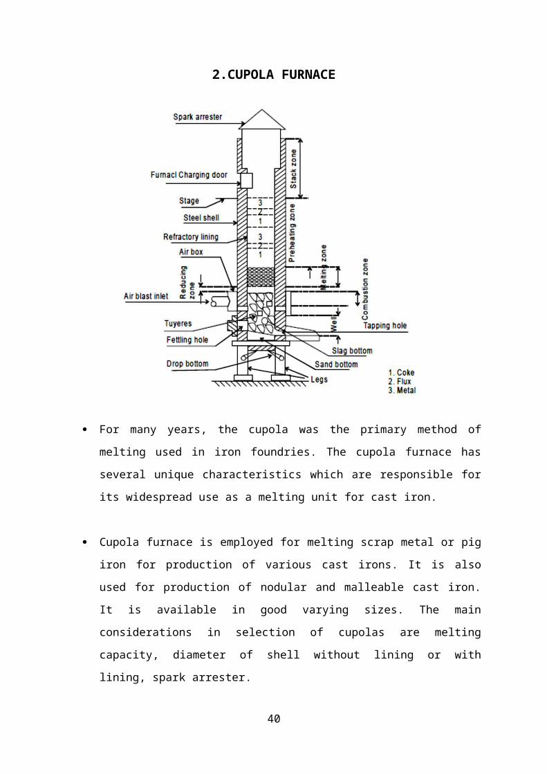
For many years, the cupola was the primary method of melting used in iron foundries.
The cupola furnace has several unique characteristics which are responsible for its
widespread use as a melting unit for cast iron.
Cupola furnace is employed for melting scrap metal or pig iron for production of
various cast irons. It is also used for production of nodular and malleable cast iron. It
is available in good varying sizes. The main considerations in selection of cupolas are
melting capacity, diameter of shell without lining or with lining, spark arrester.
Shape
A typical cupola melting furnace consists of a water-cooled vertical cylinder which is lined
with refractory material.
Construction
29
The construction of a conventional cupola consists of a vertical steel shell which is
lined with a refractory brick.
The charge is introduced into the furnace body by means of an opening approximately
half way up the vertical shaft.
The charge consists of alternate layers of the metal to be melted, coke fuel and
limestone flux.
The fuel is burnt in air which is introduced through tuyeres positioned above the
hearth. The hot gases generated in the lower part of the shaft ascend and preheat the
descending charge.
Various Zones of Cupola Furnace
Various numbers of chemical reactions take place in different zones of cupola. The
construction and different zones of cupola are :
1. Well
The space between the bottom of the tuyeres and the sand bed inside the cylindrical shell
of the cupola is called as well of the cupola. As the melting occurs, the molten metal is get
collected in this portion before tapping out.
2. Combustion zone
The combustion zone of Cupola is also called as oxidizing zone. It is located between the
upper of the tuyeres and a theoretical level above it. The total height of this zone is normally
from 15 cm. to 30 cm. The combustion actually takes place in this zone by consuming the
free oxygen completely from the air blast and generating tremendous heat. The heat
generated in this zone is sufficient enough to meet the requirements of other zones of cupola.
The heat is further evolved also due to oxidation of silicon and manganese. A temperature of
about 1540°C to 1870°C is achieved in this zone. Few exothermic reactions takes place in
this zone these are represented as:
C + O2 → CO2 + Heat
30
Si + O2 → SiO2 + Heat
2Mn + O2 → 2MnO + Heat
3. Reducing zone
Reducing zone of Cupola is also known as the protective zone which is located between
the upper level of the combustion zone and the upper level of the coke bed. In this zone, CO2
is changed to CO through an endothermic reaction, as a result of which the temperature falls
from combustion zone temperature to about 1200°C at the top of this zone. The important
chemical reaction takes place in this zone which is given as under.
CO2 + C (coke) → 2CO + Heat
Nitrogen does not participate in the chemical reaction occurring in his zone as it is also the
other main constituent of the upward moving hot gases. Because of the reducing atmosphere
in this zone, the charge is protected against oxidation.
4. Melting zone
The lower layer of metal charge above the lower layer of coke bed is termed as melting
zone of Cupola. The metal charge starts melting in this zone and trickles down through coke
bed and gets collected in the well. Sufficient carbon content picked by the molten metal in
this zone is represented by the chemical reaction given as under.
3Fe + 2CO → Fe3C + CO2
5. Preheating zone
Preheating zone starts from the upper end of the melting zone and continues
up to the bottom level of the charging door. This zone contains a number of alternate
layers of coke bed, flux and metal charge. The main objective of this zone is to
preheat the charges from room temperature to about 1090°C before entering the metal
31
charge to the melting zone. The preheating takes place in this zone due to the upward
movement of hot gases. During the preheating process, the metal charge in solid form
picks up some sulphur content in this zone.
6. Stack
The empty portion of cupola above the preheating zone is called as stack. It provides the
passage to hot gases to go to atmosphere from the cupola furnace.
Charging of Cupola Furnace
Before the blower is started, the furnace is uniformly pre-heated and the metal and
coke charges, lying in alternate layers, are sufficiently heated up.
The cover plates are positioned suitably and the blower is started.
The height of coke charge in the cupola in each layer varies generally from 10 to 15
cms. The requirement of flux to the metal charge depends upon the quality of the
charged metal and scarp, the composition of the coke and the amount of ash content
present in the coke.
Working of Cupola Furnace
32
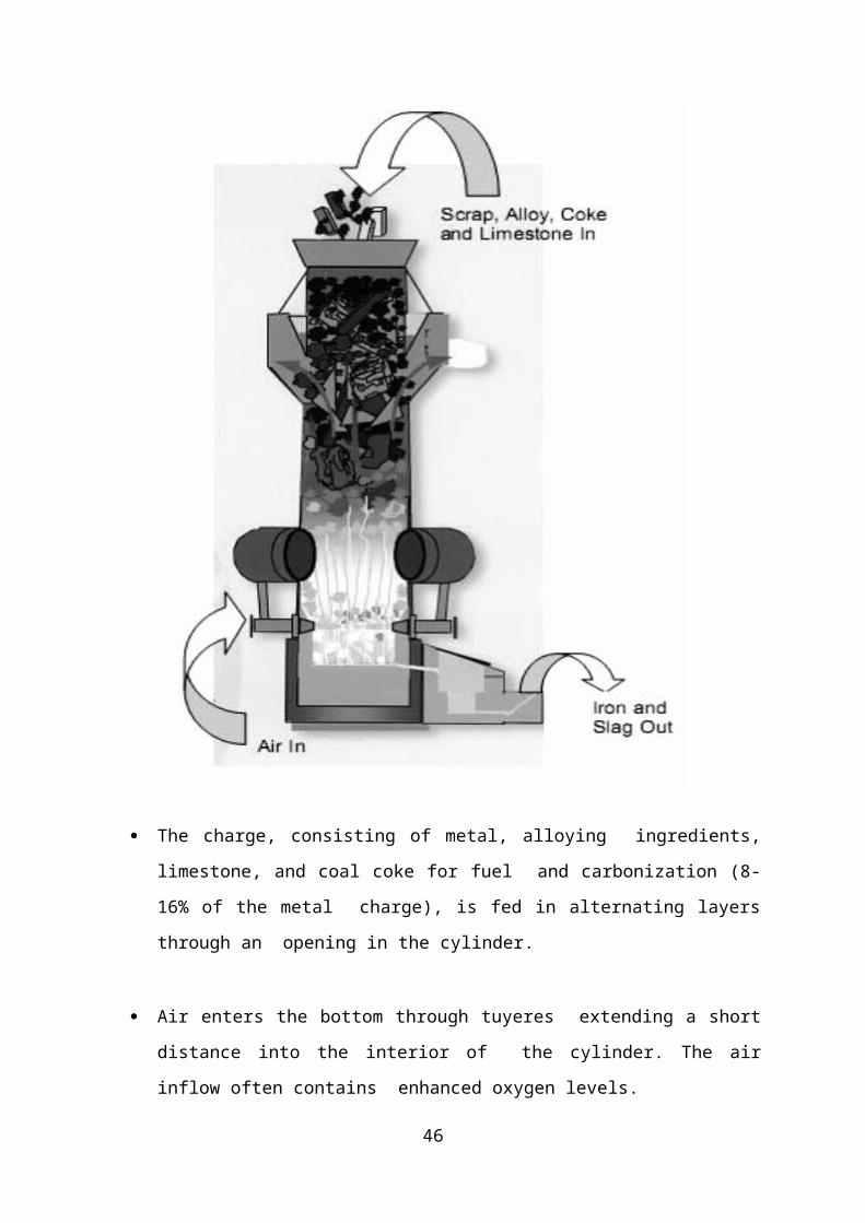
The charge, consisting of metal, alloying ingredients, limestone, and coal coke for
fuel and carbonization (8-16% of the metal charge), is fed in alternating layers
through an opening in the cylinder.
Air enters the bottom through tuyeres extending a short distance into the interior of
the cylinder. The air inflow often contains enhanced oxygen levels.
Coke is consumed. The hot exhaust gases rise up through the charge, preheating it.
This increases the energy efficiency of the furnace. The charge drops and is melted.
33
Although air is fed into the furnace, the environment is a reducing one. Burning of
coke under reducing conditions raises the carbon content of the metal charge to the
casting specifications.
As the material is consumed, additional charges can be added to the furnace.
A continuous flow of iron emerges from the bottom of the furnace.
Depending on the size of the furnace, the flow rate can be as high as 100 tones per
hour. At the metal melts it is refined to some extent, which removes contaminants.
This makes this process more suitable than electric furnaces for dirty charges.
A hole higher than the tap allows slag to be drawn off.
The exhaust gases emerge from the top of the cupola. Emission control technology is
used to treat the emissions to meet environmental standards.
Hinged doors at the bottom allow the furnace to be emptied when not in use.
Type of Molten Metal
Cupola is employed for melting scrap metals or (over 90 %) of the pig iron used in the
production of iron castings.
Gray Cast iron, nodular cast iron, some malleable iron castings and some copper base
alloys can be produced by Cupola Furnace.
Heat Energy Source
34

The cupola is a tubular furnace which produces cast iron by melting scrap and alloys
using the energy generated from the oxidation (combustion) of coke, a coal derivative.
Advantages
It is simple and economical to operate.
A cupola is capable of accepting a wide range of materials without reducing melt
quality. Dirty, oily scrap can be melted as well as a wide range of steel and iron. They
therefore play an important role in the metal recycling industry
Cupolas can refine the metal charge, removing impurities out of the slag.
From a life-cycle perspective, cupolas are more efficient and less harmful to the
environment than electric furnaces. This is because they derive energy directly from
coke rather than from electricity that first has to be generated.
The continuous rather than batch process suits the demands of a repetition foundry.
Cupolas can be used to reuse foundry by-products and to destroy other pollutants such
as VOC from the core-making area.
High melt rates
Ease of operation
Adequate temperature control
Chemical composition control
Efficiency of cupola varies from 30 to 50%.
Less floor space requirements comparing with those furnaces with same capacity.
Limitations
Since molten iron and coke are in contact with each other, certain elements like si, Mn
are lost and others like sulphur are picked up. This changes the final analysis of
molten metal.
Close temperature control is difficult to maintain
35
3. OPEN HEARTH FURNACE
Open hearth furnaces are one of a number of kinds of furnace where excess carbon
and other impurities are burnt out of pig iron to produce steel. Since steel is difficult to
manufacture owing to its high melting point, normal fuels and furnaces were insufficient and
the open hearth furnace was developed to overcome this difficulty.
In 1865, the French engineer Pierre-Émile Martin took out a license from Siemens and first
applied his regenerative furnace for making steel. Their process was known as the Siemens-
Martin process, and the furnace as an "open-hearth" furnace. Most open hearth furnaces were
closed by the early 1990s, not least because of their slow operation, being replaced by
the basic oxygen furnace or electric arc furnace.
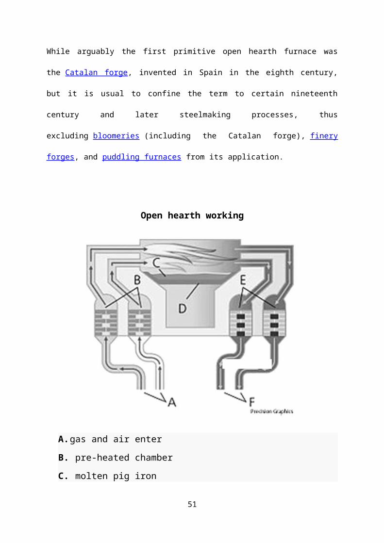
While arguably the first primitive open hearth furnace was the Catalan forge, invented in
Spain in the eighth century, but it is usual to confine the term to certain nineteenth century
and later steelmaking processes, thus excluding bloomeries (including the Catalan
forge), finery forges, and puddling furnaces from its application.
Open hearth working
36
A. gas and air enter
B. pre-heated chamber
C. molten pig iron
D. Hearth
E. heating chamber (cold)
F. gas and air exit.
The open hearth process is batch process and a batch is called a "heat". The furnace is
first inspected for possible damage. Once it is ready or repaired, it is charged with light scrap,
such as sheet metal, shredded vehicles or waste metal. Once it has melted, heavy scrap, such
as building, construction or steel milling scrap is added, together with pig iron from blast
furnaces. Once all steel has melted, slag forming agents, such as limestone, are added. The
oxygen in iron oxide and other impurities decarburize the pig iron by burning the carbon
away, forming steel. To increase the oxygen contents of the heat, iron ore can be added to the
heat.
The process is far slower than that of Bessemer converter and thus easier to control and take
samples for quality control. Preparing a heat usually takes 8 h to 8 h 30 min to complete into
steel. As the process is slow, it is not necessary to burn all the carbon away as in Bessemer
37
process, but the process can be terminated at given point when desired carbon contents has
been achieved
The furnace is tapped the same way a blast furnace is tapped; a hole is drilled on the side of
the hearth and the raw steel is let to flow out. Once all the steel has been tapped, the slag is
skimmed away. The raw steel may be cast into ingots; this process is called teeming, or it
may be used on continuous casting for the rolling mill.
The regenerators are the distinctive feature of the furnace and consist of fire-brick flues filled
with bricks set on edge and arranged in such a way as to have a great number of small
passages between them. The bricks absorb most of the heat from the outgoing waste gases
and return it later to the incoming cold gases for combustion.
4. ELECTRICAL FURNACE
Electric arc furnaces (EAF) are often used in large steel foundries and steel mills. The metal is
charged into the furnace, with additives to make recovery of slag easier, and heat to melt the metal is
produced with an electric arc from three carbon or graphite electrodes. The electric arc furnace is
lined with refractories which slowly decompose and are removed with slag. Electric arc furnaces also
usually employ air emissions equipment to capture most air pollution . Furnace operations are
discussed in detail below.
Furnace Operations
The electric arc furnace operates as a batch melting process producing batches of molten steel known
as "heats". The electric arc furnace operating cycle is called the tap-to-tap cycle and is made up of the
following operations:
Furnace Charging
The first step in the production of any heat is to select the grade of steel to be made. Preparation of the
charge bucket is an important operation, not only to ensure proper melt-in chemistry but also to ensure
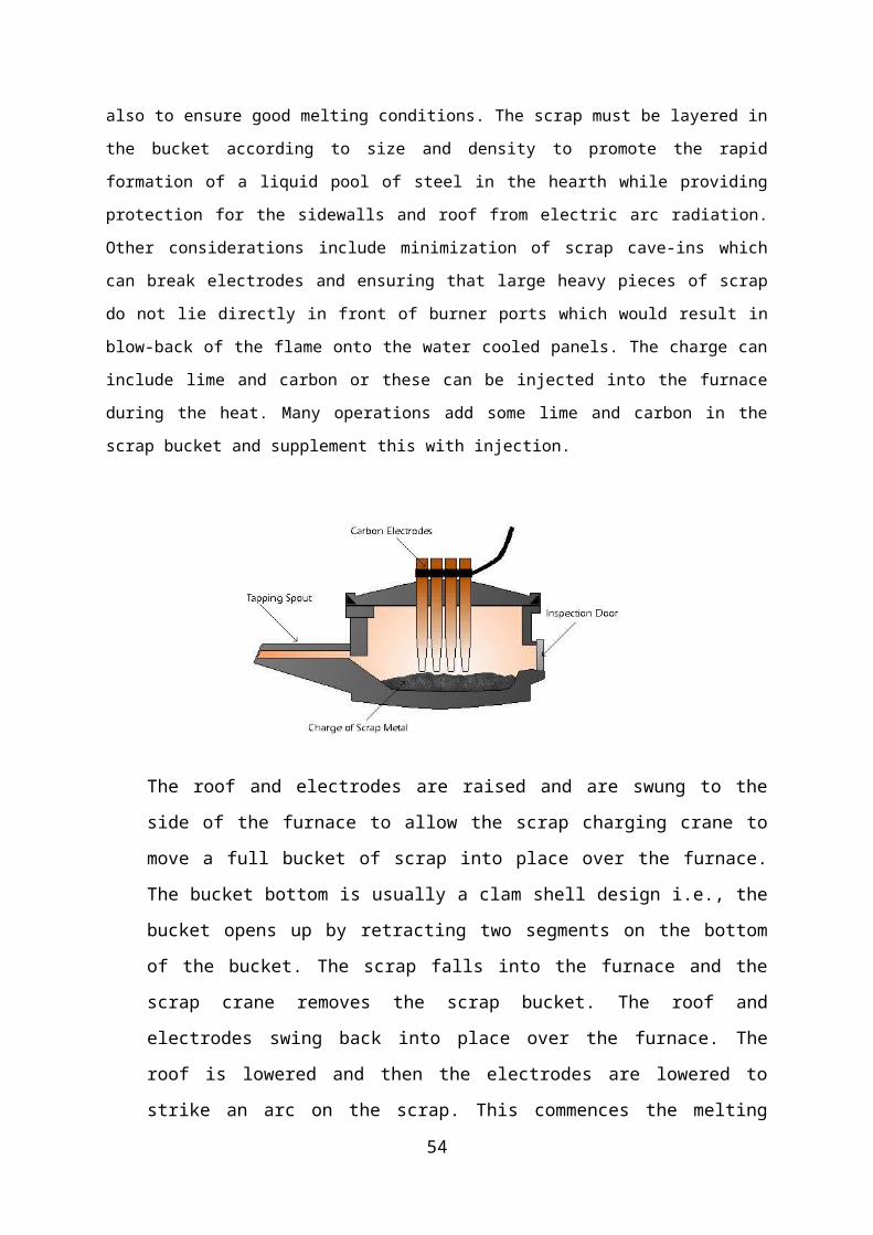
good melting conditions. The scrap must be layered in the bucket according to size and density to
promote the rapid formation of a liquid pool of steel in the hearth while providing protection for the
sidewalls and roof from electric arc radiation. Other considerations include minimization of scrap
cave-ins which can break electrodes and ensuring that large heavy pieces of scrap do not lie directly in
front of burner ports which would result in blow-back of the flame onto the water cooled panels. The
charge can include lime and carbon or these can be injected into the furnace during the heat. Many
operations add some lime and carbon in the scrap bucket and supplement this with injection.
38
The roof and electrodes are raised and are swung to the side of the furnace to allow the
scrap charging crane to move a full bucket of scrap into place over the furnace. The
bucket bottom is usually a clam shell design i.e., the bucket opens up by retracting two
segments on the bottom of the bucket. The scrap falls into the furnace and the scrap
crane removes the scrap bucket. The roof and electrodes swing back into place over the
furnace. The roof is lowered and then the electrodes are lowered to strike an arc on the
scrap. This commences the melting portion of the cycle. The number of charge buckets
of scrap required to produce a heat of steel is dependent primarily on the volume of the
furnace and the scrap density. Most modern furnaces are designed to operate with a
minimum of back-charges. This is advantageous because charging is a dead-time where
the furnace does not have power on and therefore is not melting. Minimizing these
dead-times helps to maximize the productivity of the furnace. In addition, energy is lost
every time the furnace roof is opened.
Melting
The melting period is the heart of EAF operations. Melting is accomplished by
supplying energy to the furnace interior. This energy can be electrical or chemical. Electrical
energy is supplied via the graphite electrodes and is usually the largest contributor in melting
operations. Initially, an intermediate voltage tap is selected until the electrodes bore into the
scrap. Usually, light scrap is placed on top of the
Principle of Metal Casting
39
charge to accelerate bore-in. Approximately 15 % of the scrap is melted during the
initial bore-in period. After a few minutes, the electrodes will have penetrated the scrap
sufficiently so that a long arc (high voltage) tap can be used without fear of radiation
damage to the roof. The long arc maximizes the transfer of power to the scrap and a
liquid pool of metal will form in the furnace hearth. At the start of melting the arc is
erratic and unstable. Wide swings in current are observed accompanied by rapid
movement of the electrodes. As the furnace atmosphere heats up the arc stabilizes and
once the molten pool is formed, the arc becomes quite stable and the average power
input increases.
Chemical energy is supplied via several sources including oxy-fuel burners and oxygen
lances. Oxy-fuel burners burn natural gas using oxygen or a blend of oxygen and air.
Heat is transferred to the scrap by flame radiation and convection by the hot products of
combustion. Heat is transferred within the scrap by conduction. Large pieces of scrap
take longer to melt into the bath than smaller pieces. In some operations, oxygen is
injected via a consumable pipe lance to “cut” the scrap. The oxygen reacts with the hot
scrap and burns iron to produce intense heat for cutting the scrap. Once a molten pool
of steel is generated in the furnace, oxygen can be lanced directly into the bath. This
oxygen will react with several components in the bath including, aluminum, silicon,
manganese, phosphorus, carbon and iron. All of these reactions are exothermic (i.e.,
they generate heat) and supply additional energy to aid in the melting of the scrap. The
metallic oxides that are formed will end up in the slag. The reaction of oxygen with
carbon in the bath produces carbon monoxide, which either burns in the furnace if there
is sufficient oxygen, and/or is exhausted through the direct evacuation system where it
is burned and conveyed to the pollution control system.
Refining
Refining operations in the electric arc furnace have traditionally involved the removal
of phosphorus, sulphur, aluminum, silicon, manganese and carbon from the steel. In
recent times, dissolved gases, especially hydrogen and nitrogen, have been recognized
as a concern. Traditionally, refining operations were carried out following meltdown
i.e., once a flat bath was achieved. These refining reactions are all dependent on the
availability of oxygen. Oxygen was lanced at the end of meltdown to lower the bath
carbon content to the desired level for tapping. Most of the compounds which are to be
removed during refining have a higher affinity for oxygen than the carbon. Thus the
40
oxygen will preferentially react with these elements to form oxides which float out of
the steel and into the slag.
In modern EAF operations, especially those operating with a "hot heel" of molten steel
and slag retained from the prior heat, oxygen may be blown into the bath throughout
most of the heat. As a result, some of the melting and refining operations occur
simultaneously.
Phosphorus and sulphur occur normally in the furnace charge in higher concentrations than
are generally permitted in steel and must be removed. Unfortunately the conditions
favourable for removing phosphorus are the opposite of those promoting the removal of
sulphur. Phosphorus removal is usually carried out as early as possible in the heat. Hot heel
practice is very beneficial for phosphorus removal because oxygen can be lanced into the
bath while its temperature is quite low. Early in the heat the slag will contain high FeO levels
carried over from the previous heat thus aiding in phosphorus removal. High slag basicity
(i.e., high lime content) is also beneficial for phosphorus removal but care must be taken not
to saturate the slag with lime. This will lead to an increase in slag viscosity, which will make
the slag less effective. Sometimes fluorspar is added to help fluidize the slag. Stirring the bath
with inert gas like argon is also beneficial because it renews the slag/metal interface thus
improving the reaction kinetics.
FURNACE ATMOSPHERE
The surrounding in the thermal enclosure (furnace) is termed atmosphere. The atmosphere
consists of gases and is usually air. However, in some heat treatment, thermo‐mechanical
processing, sintering etc special type of atmosphere is required to
Prevent oxide formation, if the heating material is prone to oxidation.
Decarburize steel.
Control the surface chemistry of steel which means the elements must not be oxidized
or reduced during heating.
Produce “blueing” effect in steel. The blueing effect imparts a wear‐resistant and
oxidation‐ resistant surface finish.
41
reduce oxides formed on the surface.
Make the surface hard by allowing carburizing or nitriding.
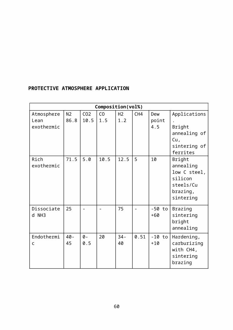
PROTECTIVE ATMOSPHERE APPLICATION
Composition(vol%)
42
Atmosphere Lean exothermic
N2 86.8
CO2 10.5
CO 1.5
H2 1.2
CH4 Dew point 4.5
Applications. Bright annealing of Cu, sintering of ferrites
Rich exothermic
71.5 5.0 10.5 12.5 5 10 Bright annealing low C steel, silicon steels/Cu brazing, sintering
Dissociated NH3
25 ‐ ‐ 75 ‐ 50 to ‐+60
Brazing sintering bright annealing
Endothermic 40 45‐ 0 0.5 ‐ 20 34 40‐ 0.51 10 to ‐+10
Hardening, carburizing with CH4, sintering brazing
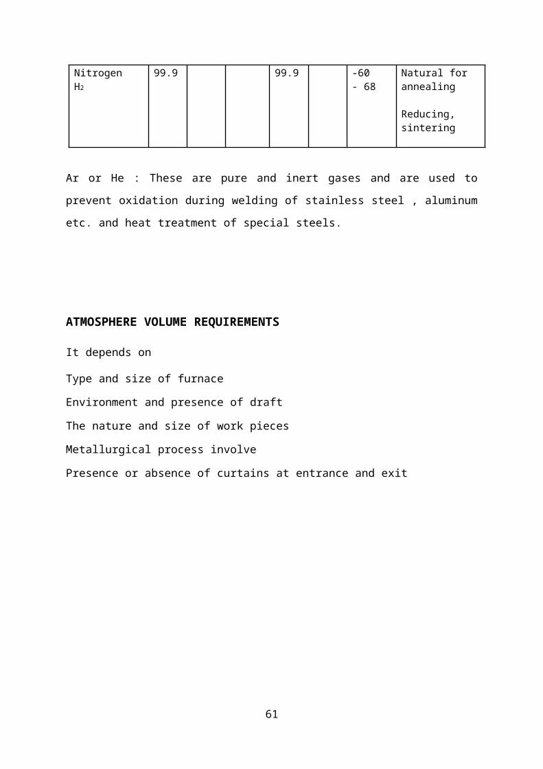
Nitrogen H2
99.9 99.9 ‐60 ‐ 68 Natural for annealing
Reducing, sintering
Ar or He : These are pure and inert gases and are used to prevent oxidation during welding
of stainless steel , aluminum etc. and heat treatment of special steels.
ATMOSPHERE VOLUME REQUIREMENTS It depends on
43
Type and size of furnace
Environment and presence of draft
The nature and size of work pieces
Metallurgical process involve
Presence or absence of curtains at entrance and exit
44
APPLICATION FOR INDUCTION FURNACE
Induction heating is used for an ever-widening range of industrial and scientific
applications: material joining processes such as brazing, soldering and curing; material
processes applications including hardening, forging, annealing and melting; and component
assembly applications such as epoxy bonding and heat staking metal into plastic. Our
engineers have also applied the technology for catheter tipping, hot heading and other
component manufacturing processes.
1. Annealing
Annealing and tempering are used to soften metal for improved ductility and
machinability, as well as to relieve residual stress. In contrast to hardening, annealing
involves a much slower heating step followed by gradual cooling of the metal. Tempering
refers to a reheating and slow cooling of metal which has become too brittle as a result of a
hardening process.
2. Bonding
Flexible, epoxy-based gaskets can be bonded to metal or other conductive material
without a third bonding agent. Our Epoxy Bonding Systems are ideal for this application.
Induction heating has been used for bonding gaskets to metal automotive parts, thermoplastic
composite bonding, and rubber washer/bumper assemblies.
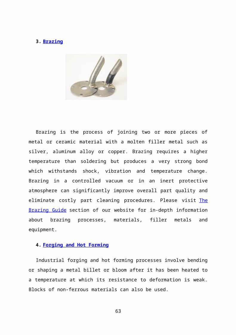
3. Brazing
45
Brazing is the process of joining two or more pieces of metal or ceramic material with a
molten filler metal such as silver, aluminum alloy or copper. Brazing requires a higher
temperature than soldering but produces a very strong bond which withstands shock,
vibration and temperature change. Brazing in a controlled vacuum or in an inert protective
atmosphere can significantly improve overall part quality and eliminate costly part cleaning
procedures. Please visit The Brazing Guide section of our website for in-depth information
about brazing processes, materials, filler metals and equipment.
4. Forging and Hot Forming
Industrial forging and hot forming processes involve bending or shaping a metal billet or
bloom after it has been heated to a temperature at which its resistance to deformation is weak.
Blocks of non-ferrous materials can also be used.
5. Fusing Nickel-Based Alloys to Steel
This application involves heating a steel boiler tube assembly to fuse a nickel-based, hard-
surfacing alloy which has been applied as a spray. The tube is coated with the alloy to
provide corrosion resistance during use; wear-resistant nickel alloys are applied to new parts
where wear or corrosion is anticipated, or to worn parts to replace metal lost through wear.
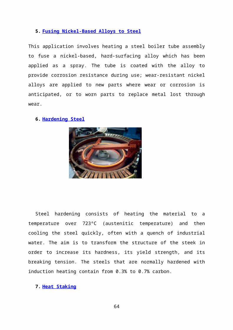
6. Hardening Steel
Steel hardening consists of heating the material to a temperature over 723ºC (austenitic
temperature) and then cooling the steel quickly, often with a quench of industrial water. The
aim is to transform the structure of the steek in order to increase its hardness, its yield
46
strength, and its breaking tension. The steels that are normally hardened with induction
heating contain from 0.3% to 0.7% carbon.
7. Heat Staking
When one piece of metal is designed to be inserted into a second piece, induction heating
can be used to "shrink fit" the two pieces together. The first or larger piece containing the
opening is heated to expand the size of the hole. The second piece is then inserted into the
opening, and as the first piece cools and shrinks back to its original size, the resulting
pressure holds the two pieces together in a strong bond.
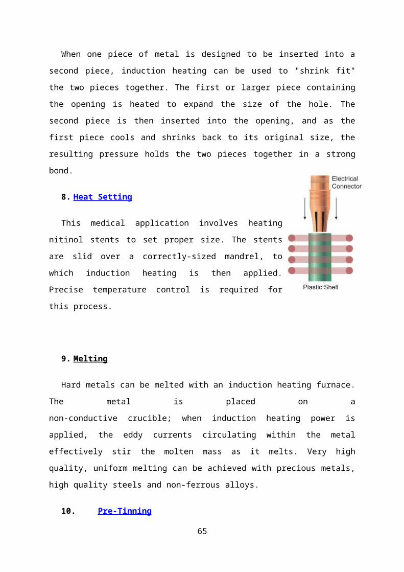
8. Heat Setting
This medical application involves heating nitinol stents to set
proper size. The stents are slid over a correctly-sized mandrel, to which
induction heating is then applied. Precise temperature control is
required for this process.
9. Melting
Hard metals can be melted with an induction heating furnace. The metal is placed on a
non-conductive crucible; when induction heating power is applied, the eddy currents
circulating within the metal effectively stir the molten mass as it melts. Very high quality,
uniform melting can be achieved with precious metals, high quality steels and non-ferrous
alloys.
10. Pre-Tinning
Induction heating can be used to quickly pre-tin solder paste in a copper electrical
connector. With the right combination of induction coil and temperature, the solder paste can
be melted within 10 seconds.
47

11. Soldering/Desoldering
Induction soldering is similar to induction brazing, but soldering is done at a lower
temperature and the bond strength is not quite as high. One unusual application involves
desoldering and removing a stainless steel lid which had previously been soldered to a
stainless steel box.
12. Susceptor Heating
A susceptor is a conductive metal material that is used to transfer heat to another
piece of metal or non-conductive material. Susceptors are often made from graphite
because it is highly resistive and very machinable, or alternatively from stainless steel,
aluminum, or other materials.
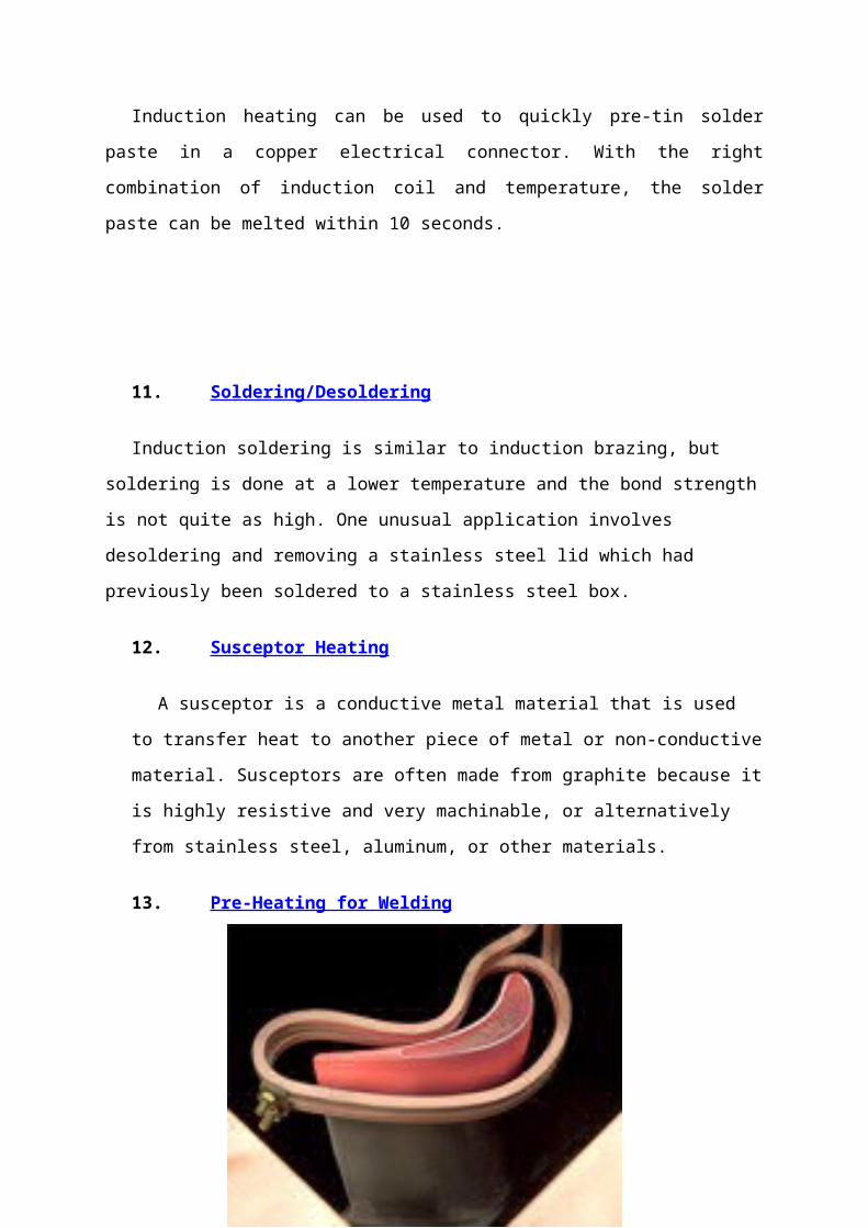
13. Pre-Heating for Welding
Induction heating can be used very effectively to preheat conductive materials for
forging, welding, hot forming and hot heading. For example, the tips of turbine engine blades
can be placed in a specially designed induction coil and heated to the desired temperature for
welding repairs. The induction preheating step improves cycle time and reduces stress on
the rest of the blade.
48
DESIGN ANALYSIS
49

LOAD APPLIED
DISPLACEMENT
50
MESHING
RESULT OF APPLIED LOAD
51
ELECTROMAGNETIC & THERMAL ANALYSIS
MESHEING
52
ELECTROMAGNETISATION
HEAT GENERATION
53
JOULE HEAT GENERATION
MAGNETIC FLUX GENERATION
54
55

PRODUCTION DRAWING
56
57
58
59
60
61
PHOTOGRAPHY
62
Assembly
Crucible
63
CONCLUSIONS
Transient Thermal analysis of mock-up induction furnace is
being carried out in this study which is highly important for
operation and control of the process.
Preliminary model : it will aid in improving the design.
The studies reveal that Aluminium -liner is effective in reducing
the electromagnetic coupling between the coil and the vessel
and thus prevents vessel from getting heated up by this effect.
The coil temperatures are above the acceptable temperature of
copper material, hence different cooling technique is to be
adopted.
These results will be compared with the experimental results
which will be obtained during the operation of mock up facility.
64
REFERENCES
[1] E. J. Davies and P. G. Simpson, Induction Heating Handbook. Maidenhead, U.K.:
McGraw-Hill, 1979.
[2] D. A. Lazor, "Induction Related Considerations in Investment Casting", Modern
Investment Casting Technical Seminar, pp 1-14, Pittsburg USA, March 27-29, 2001.
[3] K.C. Bala, "Design Analysis of an Electric Induction Furnace for Melting Aluminum
Scrap", AU Journal of Technology, vol(9), No(2):, pp83-88, Oct. 2005.
[4] P. Dorland, J.D. Wyk, and O.H. Stielau, "On the Influence of Coil Design and
Electromagnetic Configuration on the Efficiency of an Induction Melting Furnace", IEEE
Trans on IA, Vol. 36, No. 4, July/Aug. 2000.
[5] J. Lee, S. K. Lim, K. Nam and D. Choi, "Design Method of an Optimal Induction Heater
Capacitance for Maximum Power Dissipation and Minimum Power Loss Caused by
ESR", 11th IFAC Symposium on automation in Mining, Mineral and Metal processing,
Nancy, France, September 2004.
[6] A. K. Sawheny, A Course in Electrical Machine Design, J.C. Kapoor, 1981.
[7] Lloyed H. Dixon, Jr. "Eddy Current Losses in Transformer Winding and Circuit Wiring",
Texas Instruments Incorporated, 2003.
65
66


