Design Considerations and Structural Analysis of the Narrow ChannelFacility
M.P. Grunthaner and J.M. Austin
Graduate Aeronautical Laboratories,California Institute of Technology
Pasadena, California 91125
GALCIT Technical Report FM2003-003October 7, 2003
Contents
1 Original Design Considerations 61.1 Design Loading . . . . . . . . . . . . . . . . . . . . . . . . . . . . . . . . . . . . . 61.2 Sealing . . . . . . . . . . . . . . . . . . . . . . . . . . . . . . . . . . . . . . . . . . 61.3 Supports . . . . . . . . . . . . . . . . . . . . . . . . . . . . . . . . . . . . . . . . . 7
2 Detailed Structural Analysis 82.1 Introduction . . . . . . . . . . . . . . . . . . . . . . . . . . . . . . . . . . . . . . . 82.2 Narrow Channel Support Structure . . . . . . . . . . . . . . . . . . . . . . . . . . 82.3 Narrow Channel Detonation Tube . . . . . . . . . . . . . . . . . . . . . . . . . . 172.4 Narrow Channel Planar Detonation Initiator . . . . . . . . . . . . . . . . . . . . 21
3 Summary of Results 26
A Narrow Channel Support Structure Drawings 27A.1 Main Assembly (for reference), Dwg No. 1 . . . . . . . . . . . . . . . . . . . . . . 28A.2 Long Flat Plate, Dwg No. 2 . . . . . . . . . . . . . . . . . . . . . . . . . . . . . . 29A.3 Long W6 Section, Dwg No. 3 . . . . . . . . . . . . . . . . . . . . . . . . . . . . . 30A.4 Pillar Assembly, Dwg No. 4 . . . . . . . . . . . . . . . . . . . . . . . . . . . . . . 31A.5 W6 Section, Dwg No. 5 . . . . . . . . . . . . . . . . . . . . . . . . . . . . . . . . 32A.6 Upper Flat Plate, Dwg No. 6 . . . . . . . . . . . . . . . . . . . . . . . . . . . . . 33A.7 Lower Flat Plate, Dwg No. 7 . . . . . . . . . . . . . . . . . . . . . . . . . . . . . 34A.8 L Angle 1, Dwg No. 8 . . . . . . . . . . . . . . . . . . . . . . . . . . . . . . . . . 35A.9 L Angle 2, Dwg No. 9 . . . . . . . . . . . . . . . . . . . . . . . . . . . . . . . . . 36
B Narrow Channel Detonation Tube Drawings 37B.1 Notes . . . . . . . . . . . . . . . . . . . . . . . . . . . . . . . . . . . . . . . . . . 37B.2 Side Plate A (sheet 1 of 3), Dwg No. 1 . . . . . . . . . . . . . . . . . . . . . . . . 38B.3 Side Plate A (sheet 2 of 3), Dwg No. 2 . . . . . . . . . . . . . . . . . . . . . . . . 39B.4 Side Plate A (sheet 3 of 3), Dwg No. 3 . . . . . . . . . . . . . . . . . . . . . . . . 40B.5 Side Plate B (sheet 1 of 3), Dwg No. 4 . . . . . . . . . . . . . . . . . . . . . . . . 41B.6 Side Plate B (sheet 2 of 3), Dwg No. 5 . . . . . . . . . . . . . . . . . . . . . . . . 42B.7 Side Plate B (sheet 3 of 3), Dwg No. 6 . . . . . . . . . . . . . . . . . . . . . . . . 43B.8 Top Plate (sheet 1 of 2), Dwg No. 7 . . . . . . . . . . . . . . . . . . . . . . . . . 44B.9 Top Plate (sheet 2 of 2), Dwg No. 8 . . . . . . . . . . . . . . . . . . . . . . . . . 45B.10 Bottom Plate (sheet 1 of 3), Dwg No. 9 . . . . . . . . . . . . . . . . . . . . . . . 46B.11 Bottom Plate (sheet 2 of 3), Dwg No. 10 . . . . . . . . . . . . . . . . . . . . . . 47B.12 Bottom Plate (sheet 3 of 3), Dwg No. 11 . . . . . . . . . . . . . . . . . . . . . . 48B.13 End Flange, Bottom Half, Dwg No. 12 . . . . . . . . . . . . . . . . . . . . . . . . 49B.14 End Flange, Top Half, Dwg No. 13 . . . . . . . . . . . . . . . . . . . . . . . . . . 50B.15 Assembly (sheet 1 of 3), Dwg No. 14 . . . . . . . . . . . . . . . . . . . . . . . . . 51B.16 Assembly (sheet 2 of 3), Dwg No. 15 . . . . . . . . . . . . . . . . . . . . . . . . . 52B.17 Assembly (sheet 3 of 3), Dwg No. 16 . . . . . . . . . . . . . . . . . . . . . . . . . 53B.18 End Plate, Dwg No. 17 . . . . . . . . . . . . . . . . . . . . . . . . . . . . . . . . 54B.19 End Sealing Plate, Dwg No. 20 . . . . . . . . . . . . . . . . . . . . . . . . . . . . 55B.20 Window Sealing Plate, Dwg No. 21 . . . . . . . . . . . . . . . . . . . . . . . . . . 56
1
C Narrow Channel Planar Detonation Initiator Drawings 57C.1 Planar Initiator Assembly, Dwg No. 1 . . . . . . . . . . . . . . . . . . . . . . . . 58C.2 Planar Initiator - Isometric, Dwg No. 2 . . . . . . . . . . . . . . . . . . . . . . . 59C.3 Planar Initiator - Outer Dimensions, Dwg No. 3 . . . . . . . . . . . . . . . . . . 60C.4 Planar Initiator - Outer Bolts, Dwg No. 4 . . . . . . . . . . . . . . . . . . . . . . 61C.5 Planar Initiator - Outer O-Ring, Dwg No. 5 . . . . . . . . . . . . . . . . . . . . . 62C.6 Planar Initiator - Bath Tub, Dwg No. 6 . . . . . . . . . . . . . . . . . . . . . . . 63C.7 Planar Initiator - Inner Bolts, Dwg No. 7 . . . . . . . . . . . . . . . . . . . . . . 64C.8 Planar Initiator - Cutting Path, Dwg No. 8 . . . . . . . . . . . . . . . . . . . . . 65C.9 Planar Initiator - Channel Dimensions, Dwg No. 9 . . . . . . . . . . . . . . . . . 66C.10 Planar Initiator - Exit Ramp, Dwg No. 10 . . . . . . . . . . . . . . . . . . . . . . 67C.11 Cover Plate - Isometric, Dwg No. 11 . . . . . . . . . . . . . . . . . . . . . . . . . 68C.12 Cover Plate - Outer Dimensions, Dwg No. 12 . . . . . . . . . . . . . . . . . . . . 69C.13 Cover Plate - Outer Bolts, Dwg No. 13 . . . . . . . . . . . . . . . . . . . . . . . 70C.14 Cover Plate - Bath Tub, Dwg No. 14 . . . . . . . . . . . . . . . . . . . . . . . . . 71C.15 Cover Plate - Inner Bolts, Dwg No. 15 . . . . . . . . . . . . . . . . . . . . . . . . 72C.16 Cover Plate - Spark Plug, Dwg No. 16 . . . . . . . . . . . . . . . . . . . . . . . . 73
D Narrow Channel Detonation Tube Miscellaneous Documentation 74D.1 Material Certificate of Analysis and Tests (sheet 1 of 4) . . . . . . . . . . . . . . 75D.2 Material Certificate of Analysis and Tests (sheet 2 of 4) . . . . . . . . . . . . . . 76D.3 Material Certificate of Analysis and Tests (sheet 3 of 4) . . . . . . . . . . . . . . 77D.4 Material Certificate of Analysis and Tests (sheet 4 of 4) . . . . . . . . . . . . . . 78D.5 List of O-Ring Seals . . . . . . . . . . . . . . . . . . . . . . . . . . . . . . . . . . 79D.6 Side Plate Bolt Locations (sheet 1 of 2) . . . . . . . . . . . . . . . . . . . . . . . 80D.7 Side Plate Bolt Locations (sheet 2 of 2) . . . . . . . . . . . . . . . . . . . . . . . 81D.8 Shot Checklist (sheet 1 of 2) . . . . . . . . . . . . . . . . . . . . . . . . . . . . . . 82D.9 Shot Checklist (sheet 2 of 2) . . . . . . . . . . . . . . . . . . . . . . . . . . . . . . 83
2
List of Figures
1 Schematic of the NC facility. . . . . . . . . . . . . . . . . . . . . . . . . . . . . . 82 Support structure FOS distribution under 1 g of vertical loading. . . . . . . . . . 103 Enlarged view of support structure FOS distribution under 1 g of vertical loading. 114 Enlarged view of support structure displacement under 1 g of vertical loading. . . 125 Support structure FOS distribution under 2 g of horizontal loading. . . . . . . . 136 Support structure regions with FOS below 1 under 2 g of horizontal loading. . . 147 Enlarged view of support structure FOS distribution under 2 g of horizontal
loading. . . . . . . . . . . . . . . . . . . . . . . . . . . . . . . . . . . . . . . . . . 158 Support structure displacement under 2 g of horizontal loading. . . . . . . . . . . 169 Detonation tube side wall FOS distribution under 1.0 MPa of loading. . . . . . . 1710 Enlarged view of detonation tube side wall FOS distribution under 1.0 MPa of
loading. . . . . . . . . . . . . . . . . . . . . . . . . . . . . . . . . . . . . . . . . . 1811 Detonation tube side wall regions with FOS below 10. . . . . . . . . . . . . . . . 1912 Detonation tube side wall displacement under 1.0 MPa of loading. . . . . . . . . 2013 Planar detonation initiator bottom plate FOS distribution under 1.0 MPa of
loading. . . . . . . . . . . . . . . . . . . . . . . . . . . . . . . . . . . . . . . . . . 2214 Planar detonation initiator bottom plate displacement under 1.0 MPa of loading. 2315 Planar detonation initiator top plate FOS distribution under 1.0 MPa of loading. 2416 Planar detonation initiator top plate displacement under 1.0 MPa of loading. . . 2517 Main Assembly (for reference), Dwg No. 1 . . . . . . . . . . . . . . . . . . . . . . 2818 Long Flat Plate, Dwg No. 2 . . . . . . . . . . . . . . . . . . . . . . . . . . . . . . 2919 Long W6 Section, Dwg No. 3 . . . . . . . . . . . . . . . . . . . . . . . . . . . . . 3020 Pillar Assembly, Dwg No. 4 . . . . . . . . . . . . . . . . . . . . . . . . . . . . . . 3121 W6 Section, Dwg No. 5 . . . . . . . . . . . . . . . . . . . . . . . . . . . . . . . . 3222 Upper Flat Plate, Dwg No. 6 . . . . . . . . . . . . . . . . . . . . . . . . . . . . . 3323 Lower Flat Plate, Dwg No. 7 . . . . . . . . . . . . . . . . . . . . . . . . . . . . . 3424 L Angle 1, Dwg No. 8 . . . . . . . . . . . . . . . . . . . . . . . . . . . . . . . . . 3525 L Angle 2, Dwg No. 9 . . . . . . . . . . . . . . . . . . . . . . . . . . . . . . . . . 3626 ide Plate A (sheet 1 of 3), Dwg No. 1 . . . . . . . . . . . . . . . . . . . . . . . . 3827 Side Plate A (sheet 2 of 3), Dwg No. 2 . . . . . . . . . . . . . . . . . . . . . . . . 3928 Side Plate A (sheet 3 of 3), Dwg No. 3 . . . . . . . . . . . . . . . . . . . . . . . . 4029 Side Plate B (sheet 1 of 3), Dwg No. 4 . . . . . . . . . . . . . . . . . . . . . . . . 4130 Side Plate B (sheet 2 of 3), Dwg No. 5 . . . . . . . . . . . . . . . . . . . . . . . . 4231 Side Plate B (sheet 3 of 3), Dwg No. 6 . . . . . . . . . . . . . . . . . . . . . . . . 4332 Top Plate (sheet 1 of 2), Dwg No. 7 . . . . . . . . . . . . . . . . . . . . . . . . . 4433 Top Plate (sheet 2 of 2), Dwg No. 8 . . . . . . . . . . . . . . . . . . . . . . . . . 4534 Bottom Plate (sheet 1 of 3), Dwg No. 9 . . . . . . . . . . . . . . . . . . . . . . . 4635 Bottom Plate (sheet 2 of 3), Dwg No. 10 . . . . . . . . . . . . . . . . . . . . . . 4736 Bottom Plate (sheet 3 of 3), Dwg No. 11 . . . . . . . . . . . . . . . . . . . . . . 4837 End Flange, Bottom Half, Dwg No. 12 . . . . . . . . . . . . . . . . . . . . . . . . 4938 End Flange, Top Half, Dwg No. 13 . . . . . . . . . . . . . . . . . . . . . . . . . . 5039 Assembly (sheet 1 of 3), Dwg No. 14 . . . . . . . . . . . . . . . . . . . . . . . . . 5140 Assembly (sheet 2 of 3), Dwg No. 15 . . . . . . . . . . . . . . . . . . . . . . . . . 5241 Assembly (sheet 3 of 3), Dwg No. 16 . . . . . . . . . . . . . . . . . . . . . . . . . 5342 End Plate, Dwg No. 17 . . . . . . . . . . . . . . . . . . . . . . . . . . . . . . . . 5443 End Sealing Plate, Dwg No. 20 . . . . . . . . . . . . . . . . . . . . . . . . . . . . 55
3
44 Window Sealing Plate, Dwg No. 21 . . . . . . . . . . . . . . . . . . . . . . . . . . 5645 Planar Initiator Assembly, Dwg No. 1 . . . . . . . . . . . . . . . . . . . . . . . . 5846 Planar Initiator - Isometric, Dwg No. 2 . . . . . . . . . . . . . . . . . . . . . . . 5947 Planar Initiator - Outer Dimensions, Dwg No. 3 . . . . . . . . . . . . . . . . . . 6048 Planar Initiator - Outer Bolts, Dwg No. 4 . . . . . . . . . . . . . . . . . . . . . . 6149 Planar Initiator - Outer O-Ring, Dwg No. 5 . . . . . . . . . . . . . . . . . . . . . 6250 Planar Initiator - Bath Tub, Dwg No. 6 . . . . . . . . . . . . . . . . . . . . . . . 6351 Planar Initiator - Inner Bolts, Dwg No. 7 . . . . . . . . . . . . . . . . . . . . . . 6452 Planar Initiator - Cutting Path, Dwg No. 8 . . . . . . . . . . . . . . . . . . . . . 6553 Planar Initiator - Channel Dimensions, Dwg No. 9 . . . . . . . . . . . . . . . . . 6654 Planar Initiator - Exit Ramp, Dwg No. 10 . . . . . . . . . . . . . . . . . . . . . . 6755 Cover Plate - Isometric, Dwg No. 11 . . . . . . . . . . . . . . . . . . . . . . . . . 6856 Cover Plate - Outer Dimensions, Dwg No. 12 . . . . . . . . . . . . . . . . . . . . 6957 Cover Plate - Outer Bolts, Dwg No. 13 . . . . . . . . . . . . . . . . . . . . . . . 7058 Cover Plate - Bath Tub, Dwg No. 14 . . . . . . . . . . . . . . . . . . . . . . . . . 7159 Cover Plate - Inner Bolts, Dwg No. 15 . . . . . . . . . . . . . . . . . . . . . . . . 7260 Cover Plate - Spark Plug, Dwg No. 16 . . . . . . . . . . . . . . . . . . . . . . . . 7361 Material Certificate of Analysis and Tests (sheet 1 of 4) . . . . . . . . . . . . . . 7562 Material Certificate of Analysis and Tests (sheet 2 of 4) . . . . . . . . . . . . . . 7663 Material Certificate of Analysis and Tests (sheet 3 of 4) . . . . . . . . . . . . . . 7764 Material Certificate of Analysis and Tests (sheet 4 of 4) . . . . . . . . . . . . . . 7865 Side Plate Bolt Locations (sheet 1 of 2) . . . . . . . . . . . . . . . . . . . . . . . 8066 Side Plate Bolt Locations (sheet 2 of 2) . . . . . . . . . . . . . . . . . . . . . . . 8167 Shot Checklist (sheet 1 of 2) . . . . . . . . . . . . . . . . . . . . . . . . . . . . . . 8268 Shot Checklist (sheet 2 of 2) . . . . . . . . . . . . . . . . . . . . . . . . . . . . . . 83
4
List of Tables
1 Materials and material strengths used in the support structure analysis. . . . . . 92 Materials and material strengths used in the detonation tube analysis. . . . . . . 173 Materials and material strengths used in the planar detonation initiator analysis. 214 Maximum static loadings for no yielding and minimal yielding for the various
Narrow Channel structures. . . . . . . . . . . . . . . . . . . . . . . . . . . . . . . 265 Maximum safe CJ pressures for no yielding and minimal yielding for the various
NC structures. . . . . . . . . . . . . . . . . . . . . . . . . . . . . . . . . . . . . . 266 List of O-Ring Seals . . . . . . . . . . . . . . . . . . . . . . . . . . . . . . . . . . 79
5
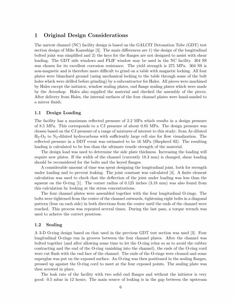
1 Original Design Considerations
The narrow channel (NC) facility design is based on the GALCIT Detonation Tube (GDT) testsection design of Mike Kaneshige [3]. The main differences are 1) the design of the longitudinalbolted joint was simplified and 2) the keys for the flanges are not designed to assist with shearloading. The GDT side windows and PLIF window may be used in the NC facility. 304 SSwas chosen for its excellent corrosion resistance. The yield strength is 275 MPa. 304 SS isnon-magnetic and is therefore more difficult to grind on a table with magnetic locking. All fourplates were blanchard ground (using mechanical locking to the table through some of the boltholes which were drilled before grinding) by a subcontractor for Hales. All pieces were machinedby Hales except the initiator, window sealing plates, end flange sealing plates which were madeby the Aeroshop. Hales also supplied the material and checked the assembly of the pieces.After delivery from Hales, the internal surfaces of the four channel plates were hand-sanded toa mirror finish.
1.1 Design Loading
The facility has a maximum reflected pressure of 2.2 MPa which results in a design pressureof 8.5 MPa. This corresponds to a CJ pressure of about 0.85 MPa. The design pressure waschosen based on the CJ pressure of a range of mixtures of interest to this study: from Ar-dilutedH2-O2 to N2-diluted hydrocarbons with sufficiently large cell size for flow visualization. Thereflected pressure in a DDT event was estimated to be 16 MPa (Shepherd 92). The resultingloading is calculated to be less than the ultimate tensile strength of the material.
The design load was used to determine the side plate thickness. Increasing the loading willrequire new plates. If the width of the channel (currently 18.3 mm) is changed, shear loadingshould be reconsidered for the bolts and the keyed flanges.
A considerable amount of time was spent designing the longitudinal joint, both for strengthunder loading and to prevent leaking. The joint constant was calculated [4]. A finite elementcalculation was used to check that the deflection of the joint under loading was less than thesqueeze on the O-ring [1]. The corner radius of 0.125 inches (3.18 mm) was also found fromthis calculation by looking at the stress concentrations.
The four channel plates were assembled together with the four longitudinal O-rings. Thebolts were tightened from the center of the channel outwards, tightening eight bolts in a diagonalpattern (four on each side) in both directions from the center until the ends of the channel werereached. This process was repeated several times. During the last pass, a torque wrench wasused to acheive the correct prestress.
1.2 Sealing
A 3-D O-ring design based on that used in the previous GDT test section was used [3]. Fourlongitudinal O-rings run in grooves between the four channel plates. After the channel wasbolted together (and after allowing some time to let the O-ring relax so as to avoid the rubbercontracting and the end of the O-ring vanishing into the channel), the ends of the O-ring cordwere cut flush with the end face of the channel. The ends of the O-rings were cleaned and somesuperglue was put on the exposed surface. An O-ring was then positioned in the sealing flanges,pressed up against the O-ring cord to meet at the four exposed points. The sealing plate wasthen screwed in place.
The leak rate of the facility with two solid end flanges and without the initiator is verygood: 0.5 mbar in 12 hours. The main source of leaking is in the gap between the upstream
6
flange and the initiator flange, which is very dependent on how perpendicularly the initiatoris mounted. A second leak source is the through bolts which clamp the initiator. These werefilled up with RTV silicone.
A helium pressure test was not done since we had considerable experience with facilitiesdesigned in this manner.
1.3 Supports
The supports were designed using SolidWorks to check the cantilevering displacement. Thejacks under the three supports are actually redundent. They were put there to help during theassembly of the support system and left in place as an extra safety measure. A 1 g sidewaysearthquake loading was also considered in the design.
Using an extra precision level, the top plate of the supports was shimmed to be level intwo planes to within 0.25 mm (10 mil). The channel slides on THK brand railings located onthe top plate of the support. These were aligned using two methods: an alignment laser and astretched piano wire.
7
2 Detailed Structural Analysis
2.1 Introduction
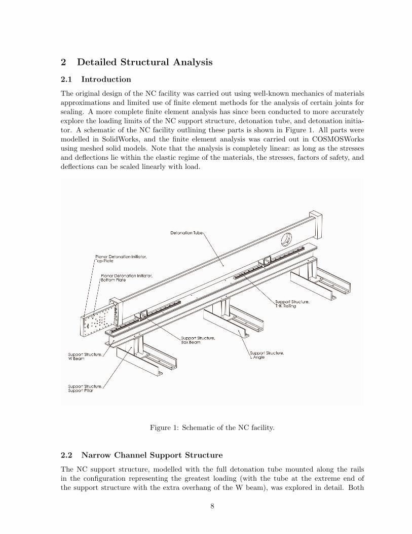
The original design of the NC facility was carried out using well-known mechanics of materialsapproximations and limited use of finite element methods for the analysis of certain joints forsealing. A more complete finite element analysis has since been conducted to more accuratelyexplore the loading limits of the NC support structure, detonation tube, and detonation initia-tor. A schematic of the NC facility outlining these parts is shown in Figure 1. All parts weremodelled in SolidWorks, and the finite element analysis was carried out in COSMOSWorksusing meshed solid models. Note that the analysis is completely linear: as long as the stressesand deflections lie within the elastic regime of the materials, the stresses, factors of safety, anddeflections can be scaled linearly with load.
Figure 1: Schematic of the NC facility.
2.2 Narrow Channel Support Structure
The NC support structure, modelled with the full detonation tube mounted along the railsin the configuration representing the greatest loading (with the tube at the extreme end ofthe support structure with the extra overhang of the W beam), was explored in detail. Both
8
a standard 1 g vertical loading and a 2 g horizontal loading to simulate an earthquake wereconsidered. The materials and material strengths for the various components are shown inTable 1.
Yield UltimateMaterial Strength [ksi] Strength [ksi] Components
plain carbon steel 32 58 L angles, support pillars,W beam, box beams
AISI 304 SS 30 75 detonation tube walls,THK railing, THK slider
Al 6061-T6 35 38 detonation tube endflanges
Table 1: Materials and material strengths used in the support structure analysis.
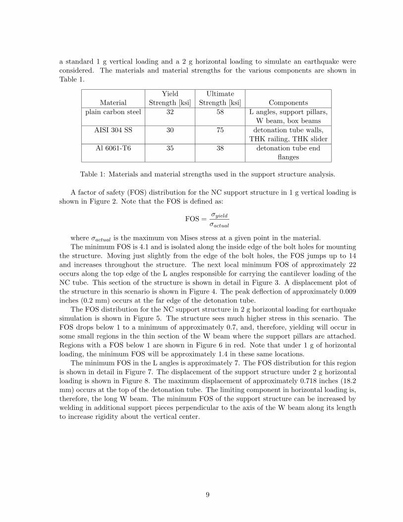
A factor of safety (FOS) distribution for the NC support structure in 1 g vertical loading isshown in Figure 2. Note that the FOS is defined as:
FOS =σyield
σactual
where σactual is the maximum von Mises stress at a given point in the material.The minimum FOS is 4.1 and is isolated along the inside edge of the bolt holes for mounting
the structure. Moving just slightly from the edge of the bolt holes, the FOS jumps up to 14and increases throughout the structure. The next local minimum FOS of approximately 22occurs along the top edge of the L angles responsible for carrying the cantilever loading of theNC tube. This section of the structure is shown in detail in Figure 3. A displacement plot ofthe structure in this scenario is shown in Figure 4. The peak deflection of approximately 0.009inches (0.2 mm) occurs at the far edge of the detonation tube.
The FOS distribution for the NC support structure in 2 g horizontal loading for earthquakesimulation is shown in Figure 5. The structure sees much higher stress in this scenario. TheFOS drops below 1 to a minimum of approximately 0.7, and, therefore, yielding will occur insome small regions in the thin section of the W beam where the support pillars are attached.Regions with a FOS below 1 are shown in Figure 6 in red. Note that under 1 g of horizontalloading, the minimum FOS will be approximately 1.4 in these same locations.
The minimum FOS in the L angles is approximately 7. The FOS distribution for this regionis shown in detail in Figure 7. The displacement of the support structure under 2 g horizontalloading is shown in Figure 8. The maximum displacement of approximately 0.718 inches (18.2mm) occurs at the top of the detonation tube. The limiting component in horizontal loading is,therefore, the long W beam. The minimum FOS of the support structure can be increased bywelding in additional support pieces perpendicular to the axis of the W beam along its lengthto increase rigidity about the vertical center.
9
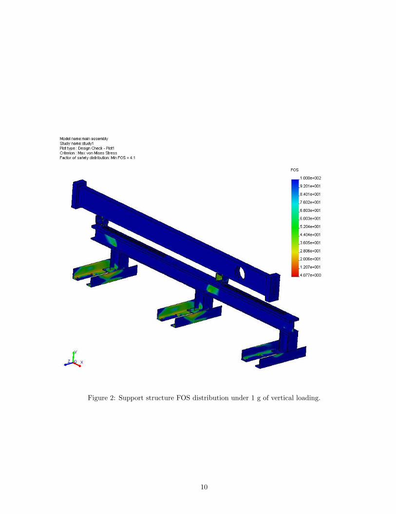
Figure 2: Support structure FOS distribution under 1 g of vertical loading.
10
Figure 3: Enlarged view of support structure FOS distribution under 1 g of vertical loading.
11
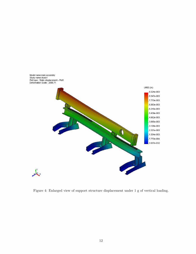
Figure 4: Enlarged view of support structure displacement under 1 g of vertical loading.
12
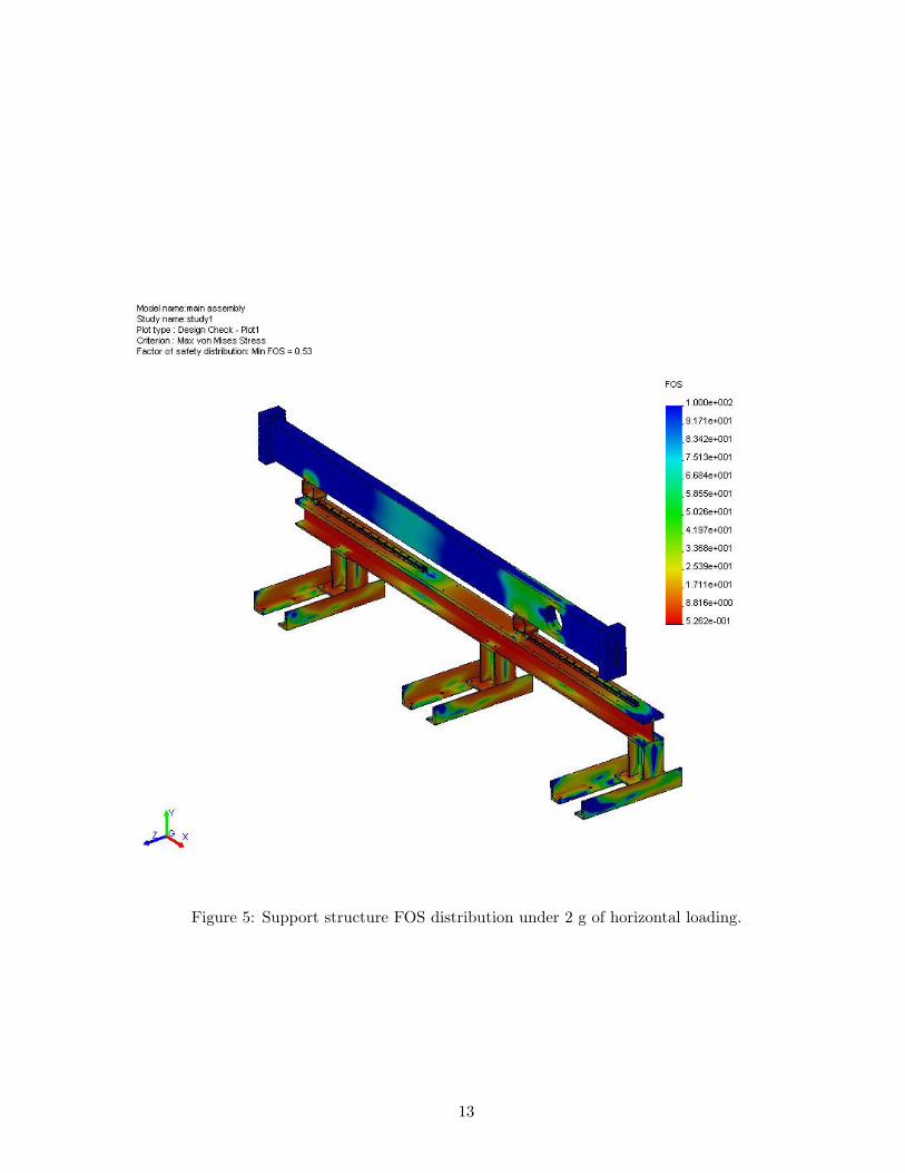
Figure 5: Support structure FOS distribution under 2 g of horizontal loading.
13
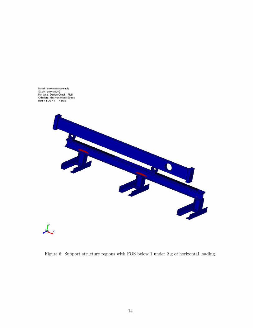
Figure 6: Support structure regions with FOS below 1 under 2 g of horizontal loading.
14
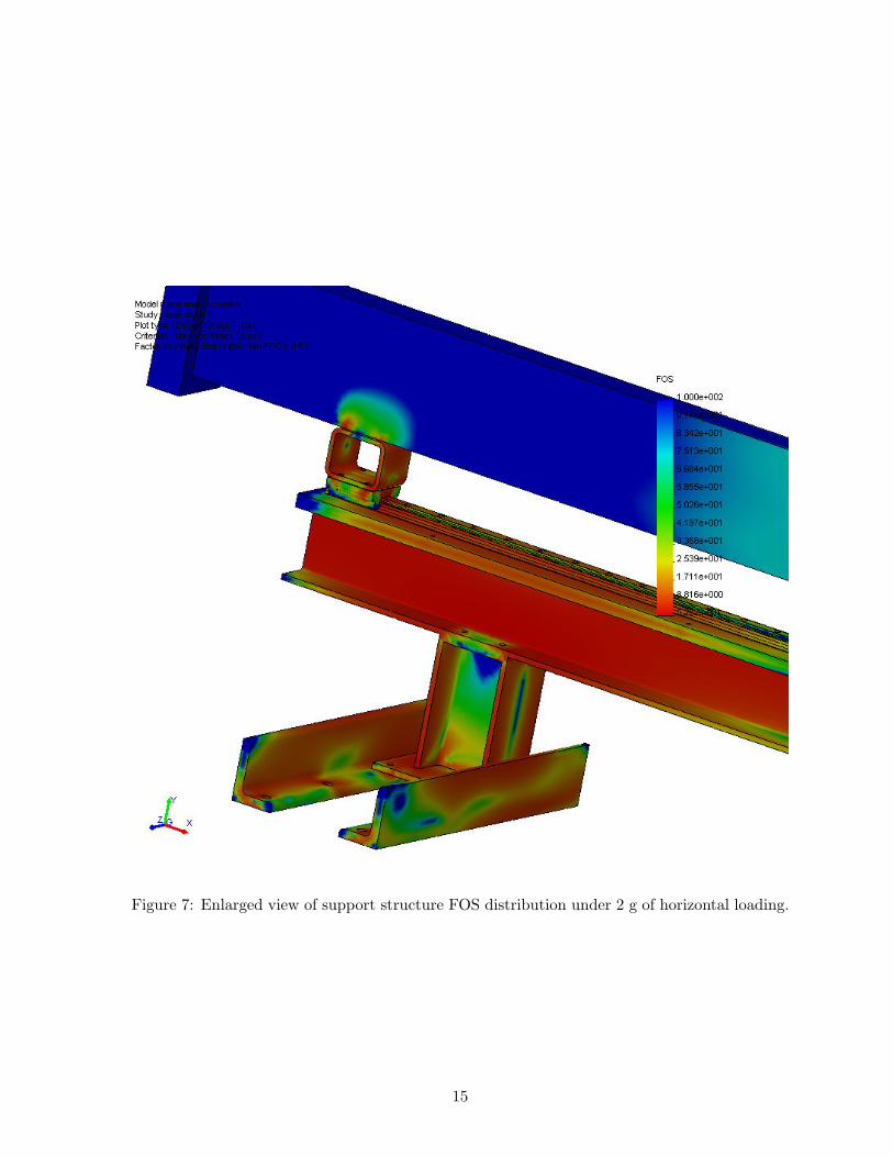
Figure 7: Enlarged view of support structure FOS distribution under 2 g of horizontal loading.
15
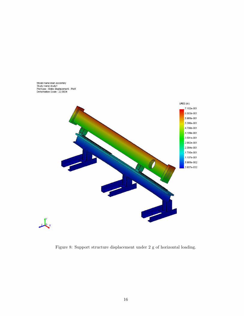
Figure 8: Support structure displacement under 2 g of horizontal loading.
16
2.3 Narrow Channel Detonation Tube
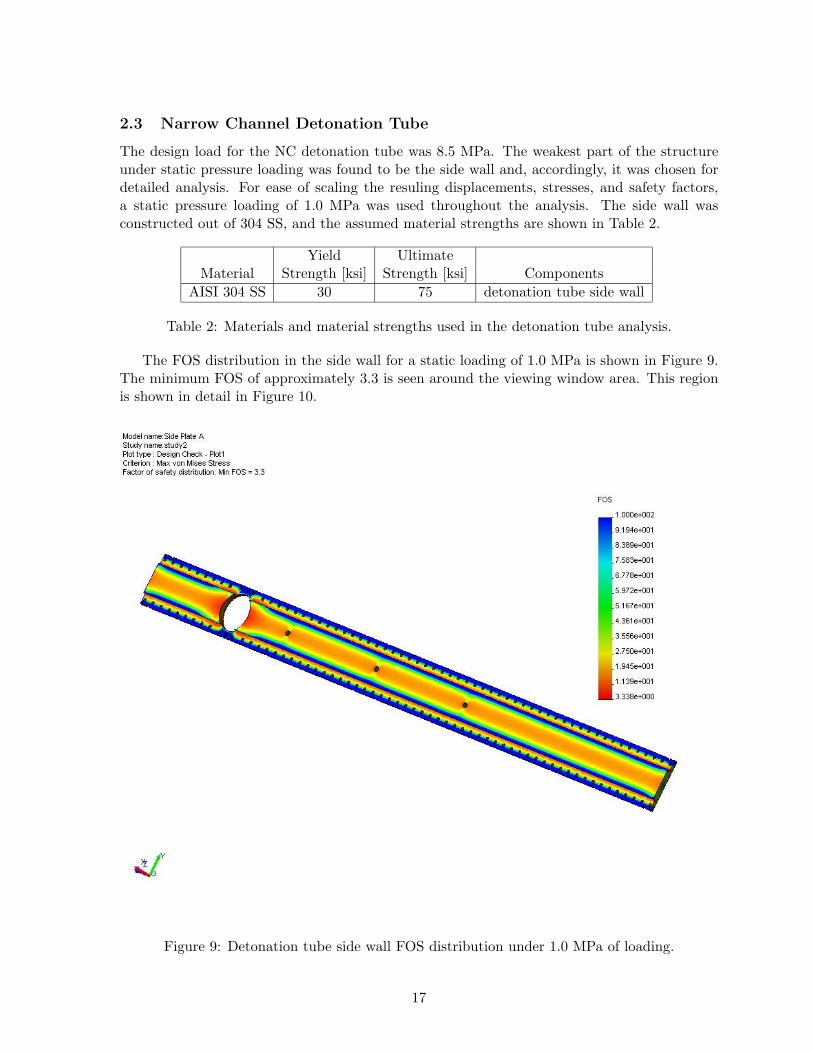
The design load for the NC detonation tube was 8.5 MPa. The weakest part of the structureunder static pressure loading was found to be the side wall and, accordingly, it was chosen fordetailed analysis. For ease of scaling the resuling displacements, stresses, and safety factors,a static pressure loading of 1.0 MPa was used throughout the analysis. The side wall wasconstructed out of 304 SS, and the assumed material strengths are shown in Table 2.
Yield UltimateMaterial Strength [ksi] Strength [ksi] Components
AISI 304 SS 30 75 detonation tube side wall
Table 2: Materials and material strengths used in the detonation tube analysis.
The FOS distribution in the side wall for a static loading of 1.0 MPa is shown in Figure 9.The minimum FOS of approximately 3.3 is seen around the viewing window area. This regionis shown in detail in Figure 10.
Figure 9: Detonation tube side wall FOS distribution under 1.0 MPa of loading.
17
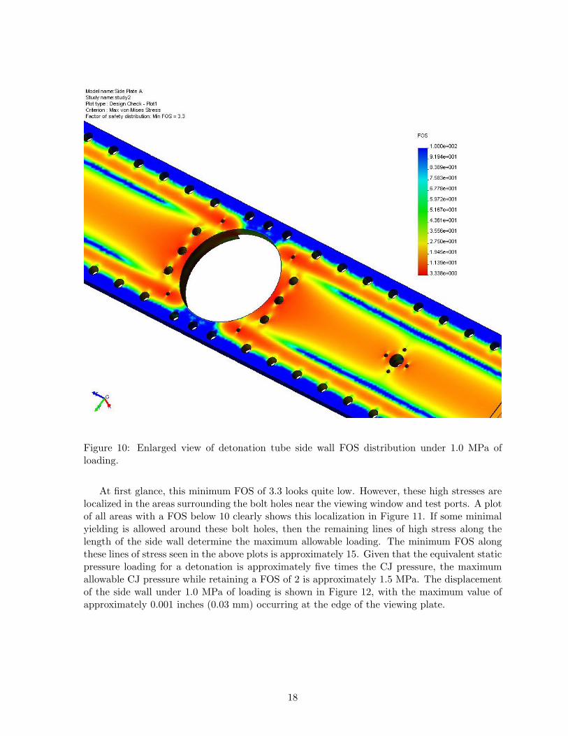
Figure 10: Enlarged view of detonation tube side wall FOS distribution under 1.0 MPa ofloading.
At first glance, this minimum FOS of 3.3 looks quite low. However, these high stresses arelocalized in the areas surrounding the bolt holes near the viewing window and test ports. A plotof all areas with a FOS below 10 clearly shows this localization in Figure 11. If some minimalyielding is allowed around these bolt holes, then the remaining lines of high stress along thelength of the side wall determine the maximum allowable loading. The minimum FOS alongthese lines of stress seen in the above plots is approximately 15. Given that the equivalent staticpressure loading for a detonation is approximately five times the CJ pressure, the maximumallowable CJ pressure while retaining a FOS of 2 is approximately 1.5 MPa. The displacementof the side wall under 1.0 MPa of loading is shown in Figure 12, with the maximum value ofapproximately 0.001 inches (0.03 mm) occurring at the edge of the viewing plate.
18
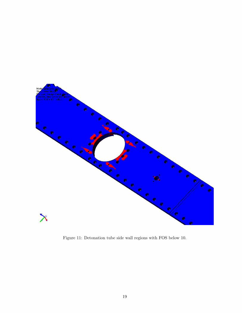
Figure 11: Detonation tube side wall regions with FOS below 10.
19
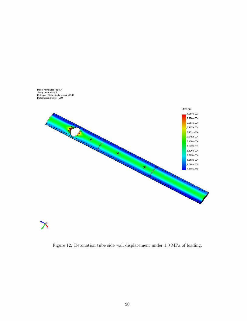
Figure 12: Detonation tube side wall displacement under 1.0 MPa of loading.
20
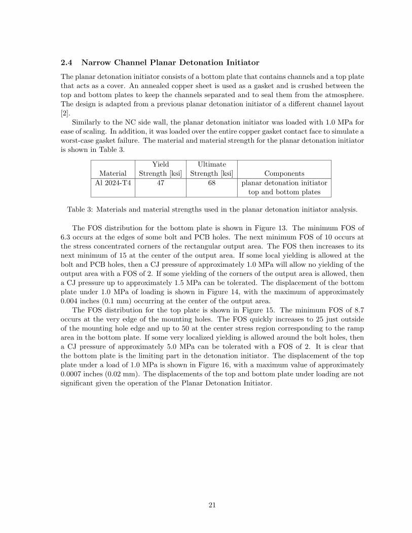
2.4 Narrow Channel Planar Detonation Initiator
The planar detonation initiator consists of a bottom plate that contains channels and a top platethat acts as a cover. An annealed copper sheet is used as a gasket and is crushed between thetop and bottom plates to keep the channels separated and to seal them from the atmosphere.The design is adapted from a previous planar detonation initiator of a different channel layout[2].
Similarly to the NC side wall, the planar detonation initiator was loaded with 1.0 MPa forease of scaling. In addition, it was loaded over the entire copper gasket contact face to simulate aworst-case gasket failure. The material and material strength for the planar detonation initiatoris shown in Table 3.
Yield UltimateMaterial Strength [ksi] Strength [ksi] Components
Al 2024-T4 47 68 planar detonation initiatortop and bottom plates
Table 3: Materials and material strengths used in the planar detonation initiator analysis.
The FOS distribution for the bottom plate is shown in Figure 13. The minimum FOS of6.3 occurs at the edges of some bolt and PCB holes. The next minimum FOS of 10 occurs atthe stress concentrated corners of the rectangular output area. The FOS then increases to itsnext minimum of 15 at the center of the output area. If some local yielding is allowed at thebolt and PCB holes, then a CJ pressure of approximately 1.0 MPa will allow no yielding of theoutput area with a FOS of 2. If some yielding of the corners of the output area is allowed, thena CJ pressure up to approximately 1.5 MPa can be tolerated. The displacement of the bottomplate under 1.0 MPa of loading is shown in Figure 14, with the maximum of approximately0.004 inches (0.1 mm) occurring at the center of the output area.
The FOS distribution for the top plate is shown in Figure 15. The minimum FOS of 8.7occurs at the very edge of the mounting holes. The FOS quickly increases to 25 just outsideof the mounting hole edge and up to 50 at the center stress region corresponding to the ramparea in the bottom plate. If some very localized yielding is allowed around the bolt holes, thena CJ pressure of approximately 5.0 MPa can be tolerated with a FOS of 2. It is clear thatthe bottom plate is the limiting part in the detonation initiator. The displacement of the topplate under a load of 1.0 MPa is shown in Figure 16, with a maximum value of approximately0.0007 inches (0.02 mm). The displacements of the top and bottom plate under loading are notsignificant given the operation of the Planar Detonation Initiator.
21
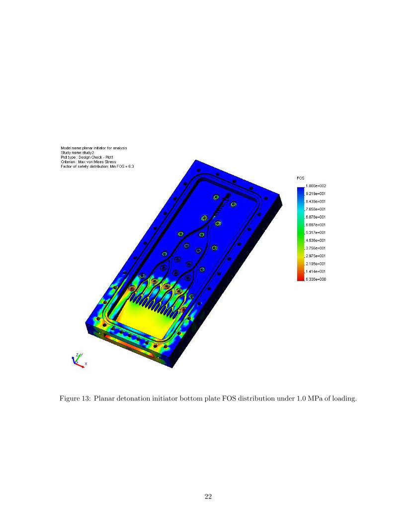
Figure 13: Planar detonation initiator bottom plate FOS distribution under 1.0 MPa of loading.
22
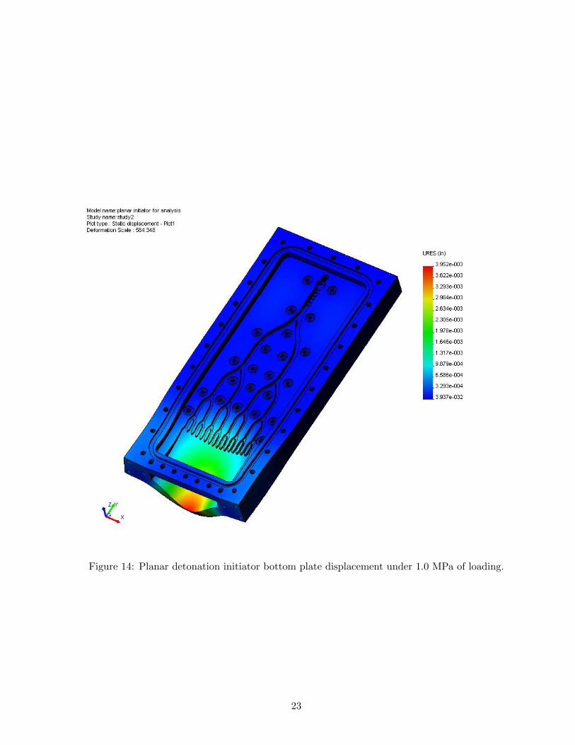
Figure 14: Planar detonation initiator bottom plate displacement under 1.0 MPa of loading.
23
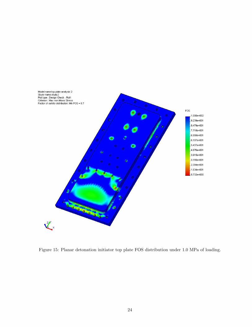
Figure 15: Planar detonation initiator top plate FOS distribution under 1.0 MPa of loading.
24
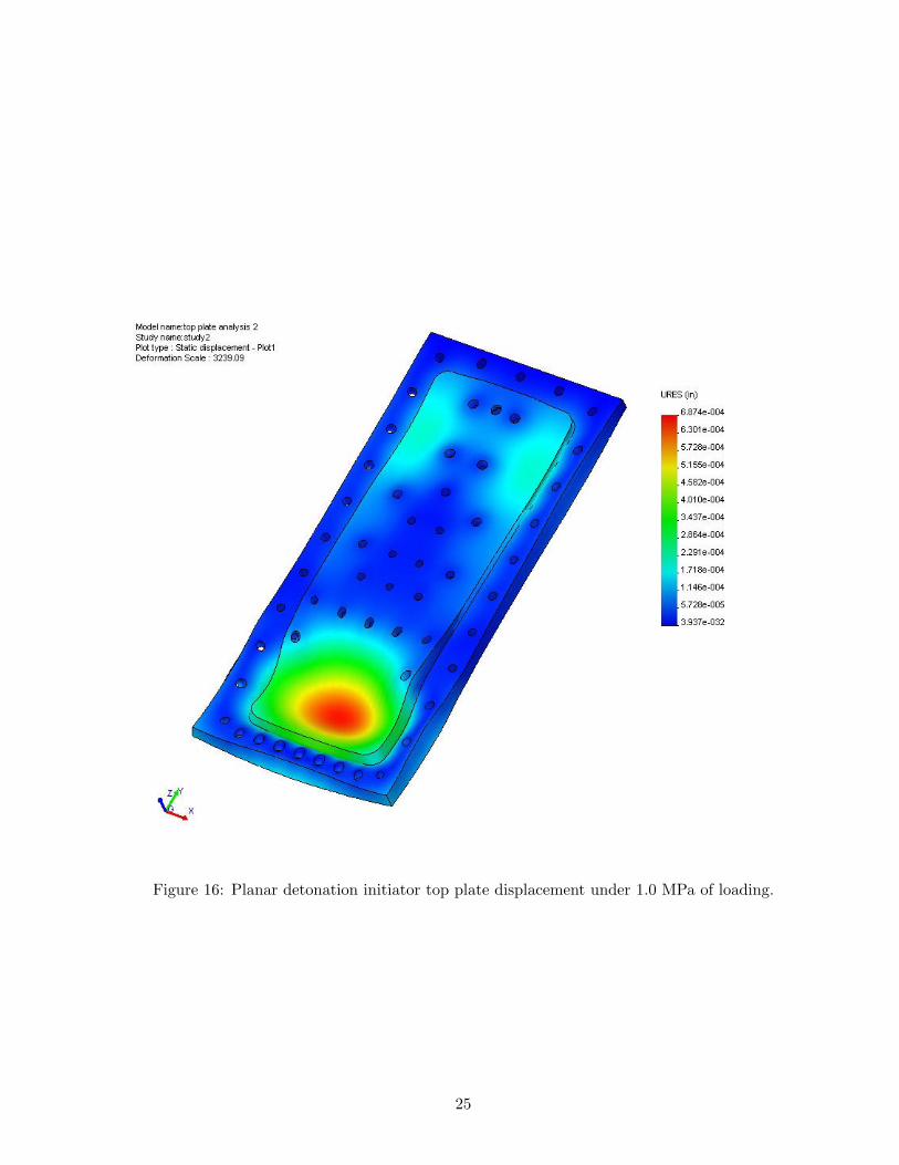
Figure 16: Planar detonation initiator top plate displacement under 1.0 MPa of loading.
25
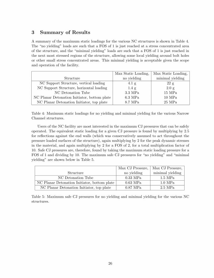
3 Summary of Results
A summary of the maximum static loadings for the various NC structures is shown in Table 4.The “no yielding” loads are such that a FOS of 1 is just reached at a stress concentrated areaof the structure, and the “minimal yielding” loads are such that a FOS of 1 is just reached inthe next most stressed regions of the structure, allowing some local yielding around bolt holesor other small stress concentrated areas. This minimal yielding is acceptable given the scopeand operation of the facility.
Max Static Loading, Max Static Loading,Structure no yielding minimal yielding
NC Support Structure, vertical loading 4.1 g 22 gNC Support Structure, horizontal loading 1.4 g 2.0 g
NC Detonation Tube 3.3 MPa 15 MPaNC Planar Detonation Initiator, bottom plate 6.3 MPa 10 MPa
NC Planar Detonation Initiator, top plate 8.7 MPa 25 MPa
Table 4: Maximum static loadings for no yielding and minimal yielding for the various NarrowChannel structures.
Users of the NC facility are most interested in the maximum CJ pressures that can be safelyoperated. The equivalent static loading for a given CJ pressure is found by multiplying by 2.5for reflections against the end walls (which was conservatively assumed to act throughout thepressure loaded surfaces of the structure), again multiplying by 2 for the peak dynamic stressesin the material, and again multiplying by 2 for a FOS of 2, for a total multiplication factor of10. Safe CJ pressures are, therefore, found by taking the maximum static loading pressure for aFOS of 1 and dividing by 10. The maximum safe CJ pressures for “no yielding” and “minimalyielding” are shown below in Table 5.
Max CJ Pressure, Max CJ Pressure,Structure no yielding minimal yielding
NC Detonation Tube 0.33 MPa 1.5 MPaNC Planar Detonation Initiator, bottom plate 0.63 MPa 1.0 MPa
NC Planar Detonation Initiator, top plate 0.87 MPa 2.5 MPa
Table 5: Maximum safe CJ pressures for no yielding and minimal yielding for the various NCstructures.
26

A Narrow Channel Support Structure Drawings
27
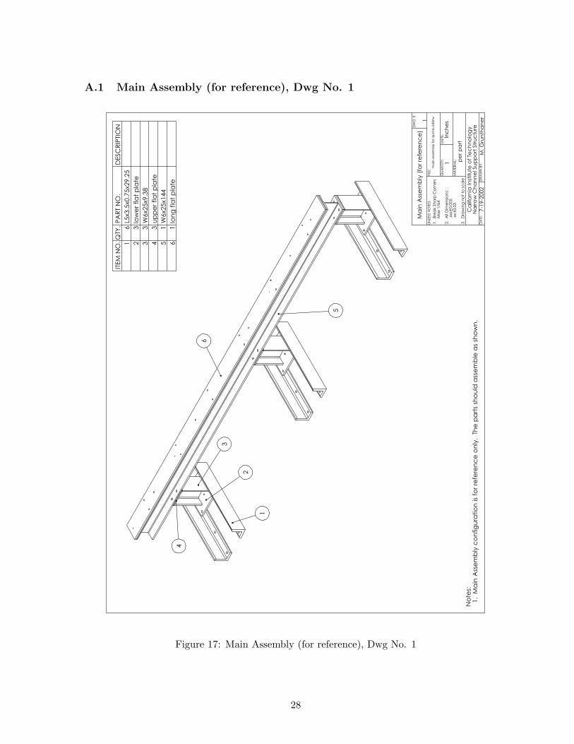
A.1 Main Assembly (for reference), Dwg No. 1
Ma
in A
sse
mb
ly (
for
refe
ren
ce
)
7-1
9-2
002
Ca
lifo
rnia
In
stitu
te o
f Te
ch
no
log
yN
arr
ow
Ch
an
ne
l Su
pp
ort
Str
uc
ture
pe
r p
art
ma
in a
sse
mb
ly f
or
qu
ote
.sld
drw
No
tes:
1. M
ain
Ass
em
bly
co
nfig
ura
tio
n is
for
refe
ren
ce
on
ly. T
he
pa
rts
sho
uld
ass
em
ble
as
sho
wn
.
1
2
3
6
4
5
1
ITEM
NO
.Q
TY.
PA
RT
NO
.D
ESC
RIP
TIO
N
16
L5x3.5
x0.7
5x29.2
5
23
low
er
fla
t p
late
33
W6x25x9.3
8
43
up
pe
r fla
t p
late
51
W6x2
5x1
44
61
lon
g f
lat
pla
te
DA
TE:
DR
AW
N B
Y:
QU
AN
TITY
:U
NIT
S:
MA
TER
IAL:
FIL
E:
UN
LESS N
OTE
D:
M. G
run
tha
ne
r
1In
ch
es
1. B
rea
k S
ha
rp C
orn
ers
Ma
x 1/6
4
2. A
ll D
ime
nsi
on
s:
.xx
x0.0
05
.xx
0.0
3
3. D
raw
ing
no
t to
sc
ale
DW
G #
:
Figure 17: Main Assembly (for reference), Dwg No. 1
28
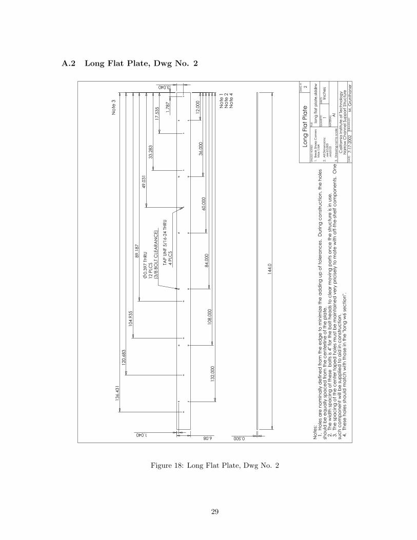
A.2 Long Flat Plate, Dwg No. 2
1.7
87
12.0
00
6.08
3.040
1.040
36.0
00
60.0
00
84.0
00
108.0
00
132.0
00
4 P
LCS
TAP
UN
F 5
/16-2
4 T
HR
U
17.5
35
33.2
83
49.0
31
89.1
87
104.9
35
120.6
83
136.4
31
12 P
LCS
(3/8
BO
LT C
LEA
RA
NC
E)
0.3
97 T
HR
U
No
tes:
1. H
ole
s a
re n
om
ina
lly d
efin
ed
fro
m t
he
ed
ge
to
min
imiz
e t
he
ad
din
g u
p o
f to
lera
nc
es.
D
urin
g c
on
stru
ctio
n, th
e h
ole
ssh
ou
ld b
e e
qu
ally
sp
ac
ed
fro
m t
he
ce
nte
rlin
e o
f th
e p
late
.
2. T
he
wid
th s
pa
cin
g o
f th
ese
b
olts
is 4
" fo
r th
e b
olt h
ea
ds
to c
lea
r m
ovin
g p
art
s o
nc
e t
he
str
uc
ture
is
in u
se.
3. T
he
sp
ac
ing
of
the
ce
nte
r ta
pe
d h
ole
s m
ust
be
ma
inta
ine
d v
ery
pric
ise
ly t
o m
ate
with
off
-th
e-s
he
lf c
om
po
ne
nts
. O
ne
suc
h c
om
po
ne
nt
will
be
su
pp
lied
to
aid
in
co
nst
ruc
tio
n.
4. T
he
se h
ole
s sh
ou
ld m
atc
h w
ith
th
ose
in
th
e "
lon
g w
6 s
ec
tio
n".
0.500
144.0
Lon
g F
lat
Pla
te
7-1
7-2
002
Ca
lifo
rnia
In
stitu
te o
f Te
ch
no
log
yN
arr
ow
Ch
an
ne
l Su
pp
ort
Str
uc
ture
Al
lon
g f
lat
pla
te.s
ldd
rw2
No
te 1
No
te 2
No
te 4
No
te 3
DA
TE:
DR
AW
N B
Y:
QU
AN
TITY
:U
NIT
S:
MA
TER
IAL:
FIL
E:
UN
LESS N
OTE
D:
M. G
run
tha
ne
r
1In
ch
es
1. B
rea
k S
ha
rp C
orn
ers
Ma
x 1/6
4
2. A
ll D
ime
nsi
on
s:
.xx
x0.0
05
.xx
0.0
3
3. D
raw
ing
no
t to
sc
ale
DW
G #
:
Figure 18: Long Flat Plate, Dwg No. 2
29
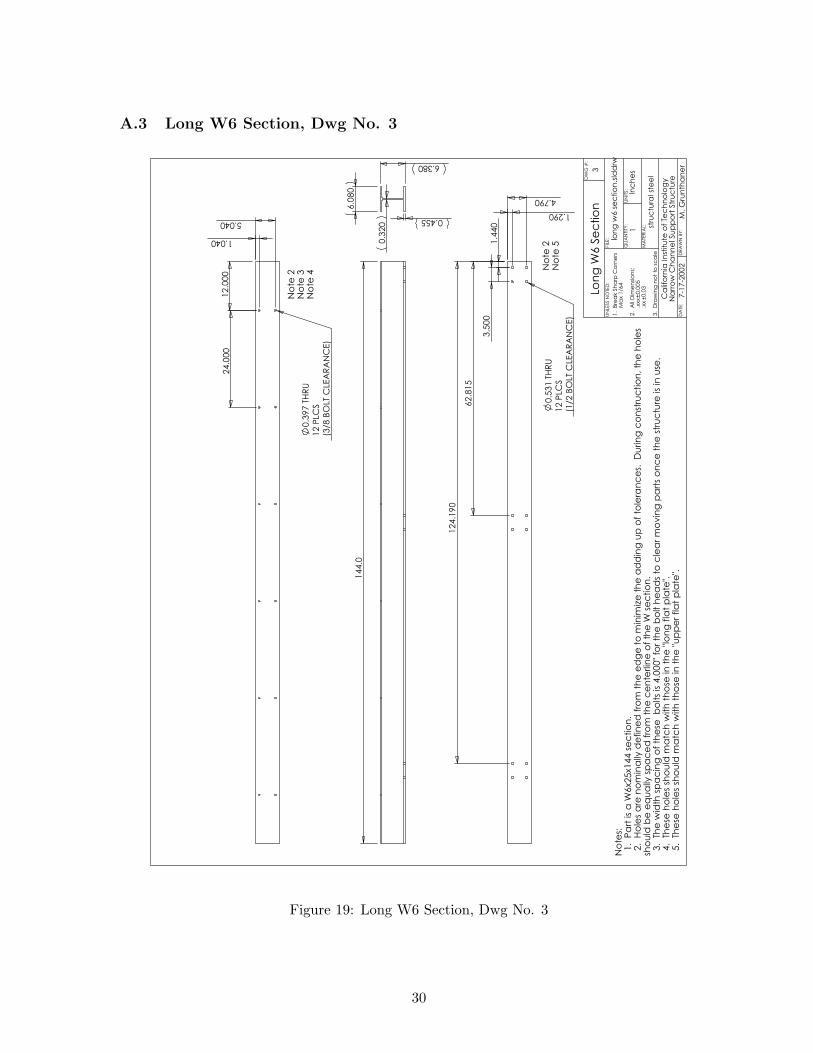
A.3 Long W6 Section, Dwg No. 3
144.0
6.0
80
6.380
0.455
0.3
20
12.0
00
24.0
00
1.040
12 P
LCS
(3/8
BO
LT C
LEA
RA
NC
E)
0.3
97 T
HR
U
5.040
No
te 2
No
te 3
No
te 4
No
te 2
No
te 5
1.4
40
3.5
00
1.290
62.8
15
124.1
90
12 P
LCS
(1/2
BO
LT C
LEA
RA
NC
E)
0.5
31 T
HR
U
4.790
lon
g w
6 s
ec
tio
n.s
ldd
rw
stru
ctu
ral st
ee
l
Ca
lifo
rnia
In
stitu
te o
f Te
ch
no
log
yN
arr
ow
Ch
an
ne
l Su
pp
ort
Str
uc
ture
7-1
7-2
002
Lon
g W
6 S
ec
tio
n
No
tes:
1. P
art
is
a W
6x25x144
se
ctio
n.
2. H
ole
s a
re n
om
ina
lly d
efin
ed
fro
m t
he
ed
ge
to
min
imiz
e t
he
ad
din
g u
p o
f to
lera
nc
es.
D
urin
g c
on
stru
ctio
n, th
e h
ole
ssh
ou
ld b
e e
qu
ally
sp
ac
ed
fro
m t
he
ce
nte
rlin
e o
f th
e W
se
ctio
n.
3. T
he
wid
th s
pa
cin
g o
f th
ese
b
olts
is 4
.000"
for
the
bo
lt h
ea
ds
to c
lea
r m
ovin
g p
art
s o
nc
e t
he
str
uc
ture
is
in u
se.
4. T
he
se h
ole
s sh
ou
ld m
atc
h w
ith
th
ose
in
th
e "
lon
g f
lat
pla
te".
5. T
he
se h
ole
s sh
ou
ld m
atc
h w
ith
th
ose
in
th
e "
up
pe
r fla
t p
late
".
3
DA
TE:
DR
AW
N B
Y:
QU
AN
TITY
:U
NIT
S:
MA
TER
IAL:
FIL
E:
UN
LESS N
OTE
D:
M. G
run
tha
ne
r
1In
ch
es
1. B
rea
k S
ha
rp C
orn
ers
Ma
x 1/6
4
2. A
ll D
ime
nsi
on
s:
.xx
x0.0
05
.xx
0.0
3
3. D
raw
ing
no
t to
sc
ale
DW
G #
:
Figure 19: Long W6 Section, Dwg No. 3
30
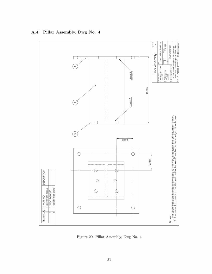
A.4 Pillar Assembly, Dwg No. 4
2.750
2.7
50
No
tes:
1. T
he
up
pe
r fla
t p
late
is
to b
e f
ille
t w
eld
ed
to
th
e W
6x2
5 s
ec
tio
n in
th
e c
on
fig
ura
tio
n s
ho
wn
.
2. T
he
lo
we
r fla
t p
late
is
to b
e f
ille
t w
eld
ed
to
th
e W
6x2
5 s
ec
tio
n in
th
e c
on
fig
ura
tio
n s
ho
wn
.
11.3
55
32
1
pill
ar
ass
em
bly
.sld
drw
stru
ctu
ral st
ee
l
Ca
lifo
rnia
In
stitu
te o
f Te
ch
no
log
yN
arr
ow
Ch
an
ne
l Su
pp
ort
Str
uc
ture
7-1
7-2
002
Pill
ar
Ass
em
bly
4
No
te 2
No
te 3
ITEM
NO
.Q
TY.
PA
RT
NO
.D
ESC
RIP
TIO
N
11
low
er
fla
t p
late
21
W6x25x1
0.3
55
31
up
pe
r fla
t p
late
DA
TE:
DR
AW
N B
Y:
QU
AN
TITY
:U
NIT
S:
MA
TER
IAL:
FIL
E:
UN
LESS N
OTE
D:
M. G
run
tha
ne
r
3In
ch
es
1. B
rea
k S
ha
rp C
orn
ers
Ma
x 1/6
4
2. A
ll D
ime
nsi
on
s:
.xx
x0.0
05
.xx
0.0
3
3. D
raw
ing
no
t to
sc
ale
DW
G #
:
Figure 20: Pillar Assembly, Dwg No. 4
31
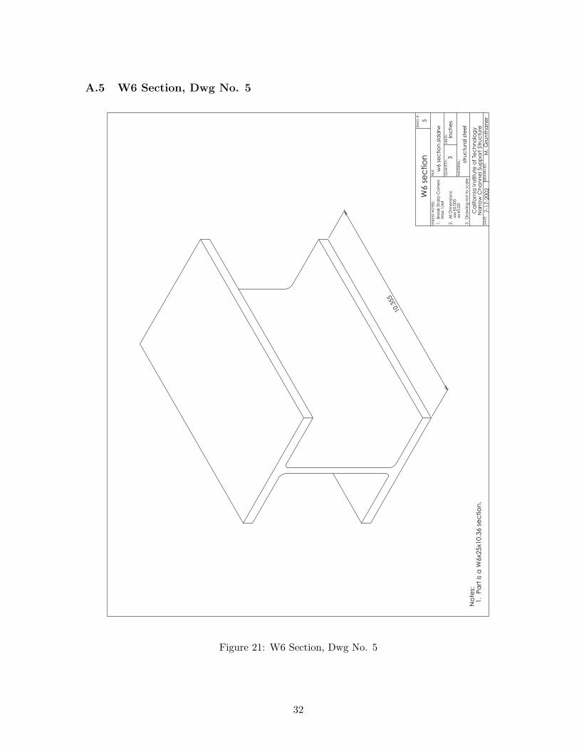
A.5 W6 Section, Dwg No. 5
10.3
55
W6 s
ec
tio
n
7-1
7-2
002
Ca
lifo
rnia
In
stitu
te o
f Te
ch
no
log
yN
arr
ow
Ch
an
ne
l Su
pp
ort
Str
uc
ture
stru
ctu
ral st
ee
l
w6 s
ec
tio
n.s
ldd
rw
No
tes:
1. P
art
is
a W
6x25x10.3
6 s
ec
tio
n.
5
DA
TE:
DR
AW
N B
Y:
QU
AN
TITY
:U
NIT
S:
MA
TER
IAL:
FIL
E:
UN
LESS N
OTE
D:
M. G
run
tha
ne
r
3In
ch
es
1. B
rea
k S
ha
rp C
orn
ers
Ma
x 1/6
4
2. A
ll D
ime
nsi
on
s:
.xx
x0.0
05
.xx
0.0
3
3. D
raw
ing
no
t to
sc
ale
DW
G #
:
Figure 21: W6 Section, Dwg No. 5
32
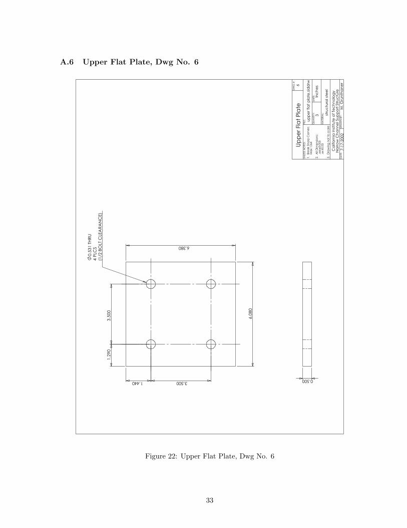
A.6 Upper Flat Plate, Dwg No. 6
6.380
6.0
80
1.440 3.500
1.2
90
3.5
00
4 P
LCS
(1/2
BO
LT C
LEA
RA
NC
E)
0.5
31 T
HR
U
up
pe
r fla
t p
late
.sld
drw
stru
ctu
ral st
ee
l
Ca
lifo
rnia
In
stitu
te o
f Te
ch
no
log
yN
arr
ow
Ch
an
ne
l Su
pp
ort
Str
uc
ture
7-1
7-2
002
Up
pe
r Fla
t P
late
6
0.500
DA
TE:
DR
AW
N B
Y:
QU
AN
TITY
:U
NIT
S:
MA
TER
IAL:
FIL
E:
UN
LESS N
OTE
D:
M. G
run
tha
ne
r
3In
ch
es
1. B
rea
k S
ha
rp C
orn
ers
Ma
x 1/6
4
2. A
ll D
ime
nsi
on
s:
.xx
x0.0
05
.xx
0.0
3
3. D
raw
ing
no
t to
sc
ale
DW
G #
:
Figure 22: Upper Flat Plate, Dwg No. 6
33
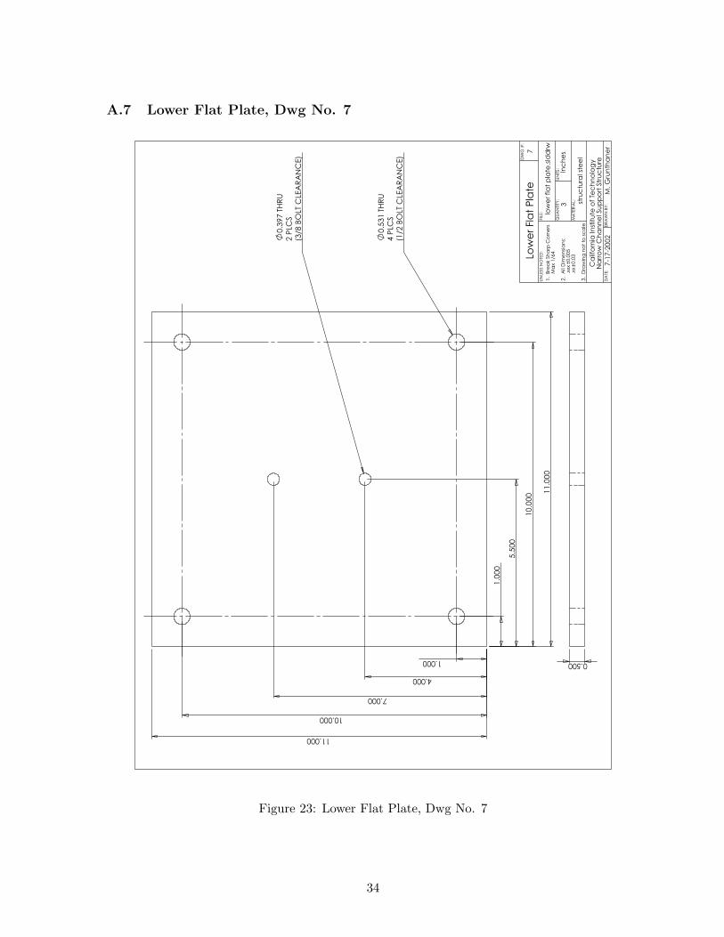
A.7 Lower Flat Plate, Dwg No. 7
4 P
LCS
(1/2
BO
LT C
LEA
RA
NC
E)
0.5
31 T
HR
U
1.0
00
1.000
10.000
10.0
00 1
1.0
00
11.000
4.000
7.000
5.5
00
2 P
LCS
(3/8
BO
LT C
LEA
RA
NC
E)
0.3
97 T
HR
U
Low
er
Fla
t P
late
7-1
7-2
002
Ca
lifo
rnia
In
stitu
te o
f Te
ch
no
log
yN
arr
ow
Ch
an
ne
l Su
pp
ort
Str
uc
ture
stru
ctu
ral st
ee
l
low
er
fla
t p
late
.sld
drw7
0.500
DA
TE:
DR
AW
N B
Y:
QU
AN
TITY
:U
NIT
S:
MA
TER
IAL:
FIL
E:
UN
LESS N
OTE
D:
M. G
run
tha
ne
r
3In
ch
es
1. B
rea
k S
ha
rp C
orn
ers
Ma
x 1/6
4
2. A
ll D
ime
nsi
on
s:
.xx
x0.0
05
.xx
0.0
3
3. D
raw
ing
no
t to
sc
ale
DW
G #
:
Figure 23: Lower Flat Plate, Dwg No. 7
34
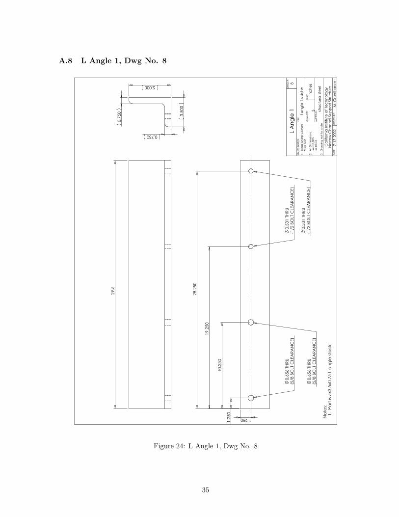
A.8 L Angle 1, Dwg No. 8
29.5
1.2
50
1.250
(5/8
BO
LT C
LEA
RA
NC
E)
0.6
56 T
HR
U
(5/8
BO
LT C
LEA
RA
NC
E)
0.6
56 T
HR
U
(1/2
BO
LT C
LEA
RA
NC
E)
0.5
31 T
HR
U
(1/2
BO
LT C
LEA
RA
NC
E)
0.5
31 T
HR
U
10.2
50
19.2
50
28.2
50
l a
ng
le 1
.sld
drw
stru
ctu
ral st
ee
l
Ca
lifo
rnia
In
stitu
te o
f Te
ch
no
log
yN
arr
ow
Ch
an
ne
l Su
pp
ort
Str
uc
ture
7-1
7-2
002L A
ng
le 1
No
tes:
1. P
art
is
5x3.5
x0.7
5 L
an
gle
sto
ck.
85.000
3.5
00
0.750
0.7
50
DA
TE:
DR
AW
N B
Y:
QU
AN
TITY
:U
NIT
S:
MA
TER
IAL:
FIL
E:
UN
LESS N
OTE
D:
M. G
run
tha
ne
r
3In
ch
es
1. B
rea
k S
ha
rp C
orn
ers
Ma
x 1/6
4
2. A
ll D
ime
nsi
on
s:
.xx
x0.0
05
.xx
0.0
3
3. D
raw
ing
no
t to
sc
ale
DW
G #
:
Figure 24: L Angle 1, Dwg No. 8
35
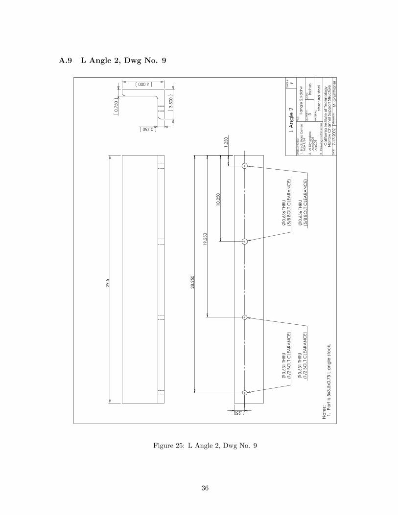
A.9 L Angle 2, Dwg No. 9
29.5
5.000
3.5
00
0.750
0.7
50
1.250
(1/2
BO
LT C
LEA
RA
NC
E)
0.5
31 T
HR
U
(1/2
BO
LT C
LEA
RA
NC
E)
0.5
31 T
HR
U
(5/8
BO
LT C
LEA
RA
NC
E)
0.6
56 T
HR
U
(5/8
BO
LT C
LEA
RA
NC
E)
0.6
56 T
HR
U
1.2
50
10.2
50
19.2
50
28.2
50
L A
ng
le 2
7-1
7-2
002
Ca
lifo
rnia
In
stitu
te o
f Te
ch
no
log
yN
arr
ow
Ch
an
ne
l Su
pp
ort
Str
uc
ture
stru
ctu
ral st
ee
l
l a
ng
le 2
.sld
drw
No
tes:
1. P
art
is
5x3.5
x0.7
5 L
an
gle
sto
ck.
9
DA
TE:
DR
AW
N B
Y:
QU
AN
TITY
:U
NIT
S:
MA
TER
IAL:
FIL
E:
UN
LESS N
OTE
D:
M. G
run
tha
ne
r
3In
ch
es
1. B
rea
k S
ha
rp C
orn
ers
Ma
x 1/6
4
2. A
ll D
ime
nsi
on
s:
.xx
x0.0
05
.xx
0.0
3
3. D
raw
ing
no
t to
sc
ale
DW
G #
:
Figure 25: L Angle 2, Dwg No. 9
36
B Narrow Channel Detonation Tube Drawings
B.1 Notes
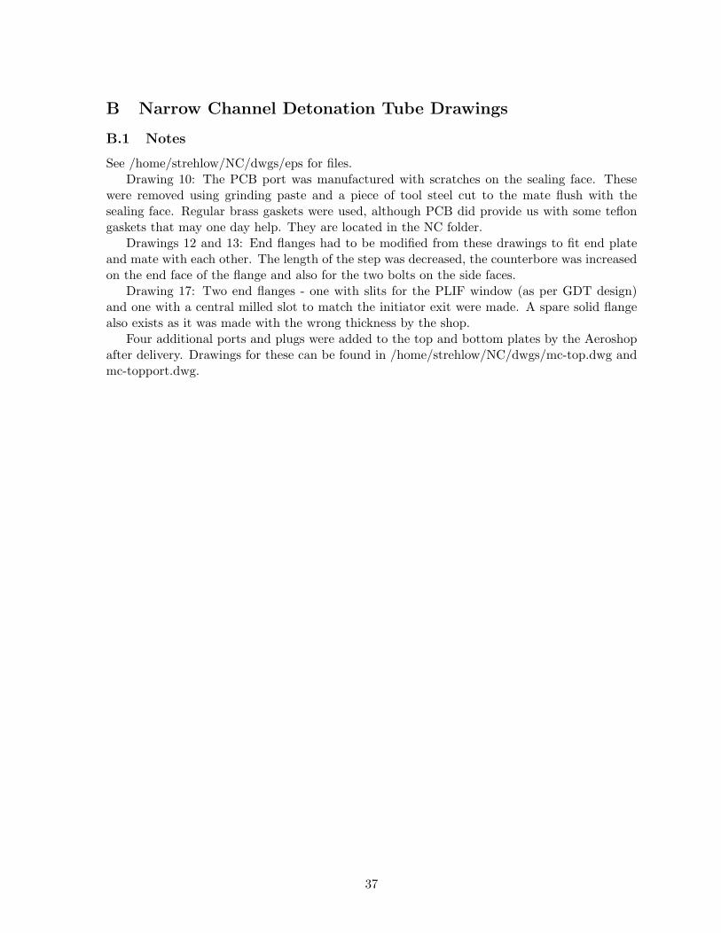
See /home/strehlow/NC/dwgs/eps for files.Drawing 10: The PCB port was manufactured with scratches on the sealing face. These
were removed using grinding paste and a piece of tool steel cut to the mate flush with thesealing face. Regular brass gaskets were used, although PCB did provide us with some teflongaskets that may one day help. They are located in the NC folder.
Drawings 12 and 13: End flanges had to be modified from these drawings to fit end plateand mate with each other. The length of the step was decreased, the counterbore was increasedon the end face of the flange and also for the two bolts on the side faces.
Drawing 17: Two end flanges - one with slits for the PLIF window (as per GDT design)and one with a central milled slot to match the initiator exit were made. A spare solid flangealso exists as it was made with the wrong thickness by the shop.
Four additional ports and plugs were added to the top and bottom plates by the Aeroshopafter delivery. Drawings for these can be found in /home/strehlow/NC/dwgs/mc-top.dwg andmc-topport.dwg.
37
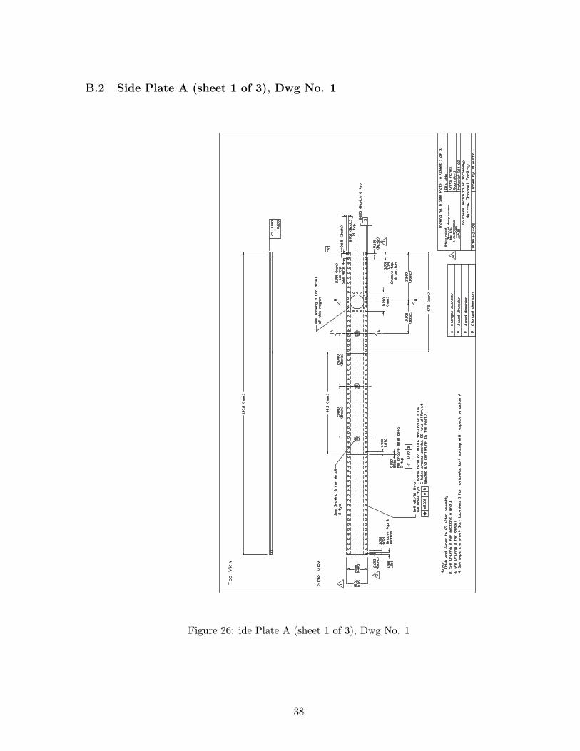
B.2 Side Plate A (sheet 1 of 3), Dwg No. 1
Figure 26: ide Plate A (sheet 1 of 3), Dwg No. 1
38
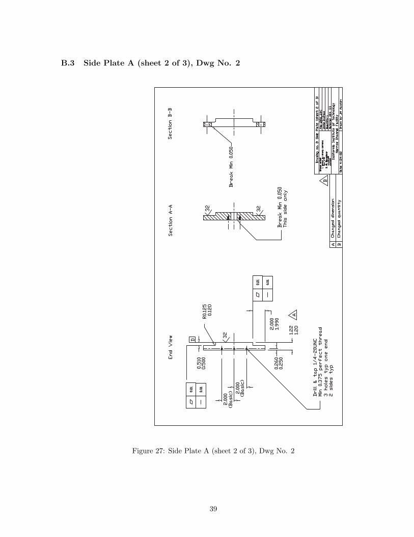
B.3 Side Plate A (sheet 2 of 3), Dwg No. 2
Figure 27: Side Plate A (sheet 2 of 3), Dwg No. 2
39
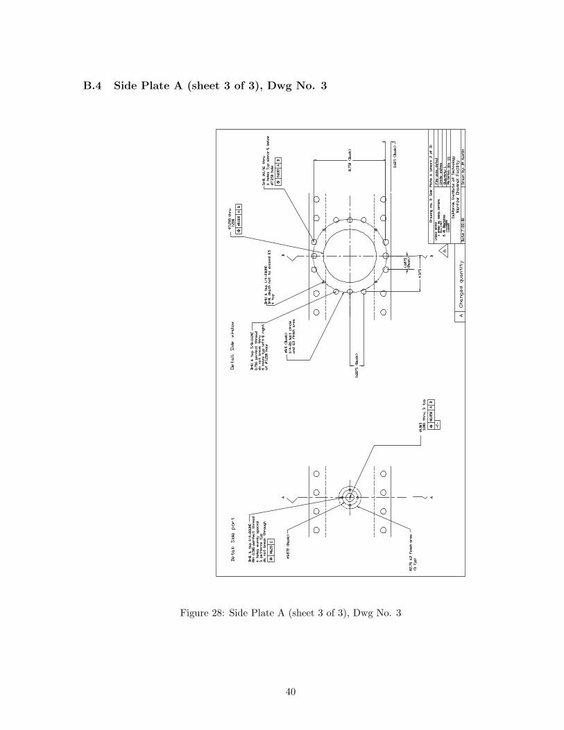
B.4 Side Plate A (sheet 3 of 3), Dwg No. 3
Figure 28: Side Plate A (sheet 3 of 3), Dwg No. 3
40
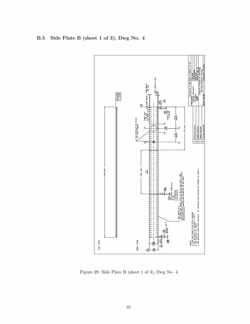
B.5 Side Plate B (sheet 1 of 3), Dwg No. 4
Figure 29: Side Plate B (sheet 1 of 3), Dwg No. 4
41
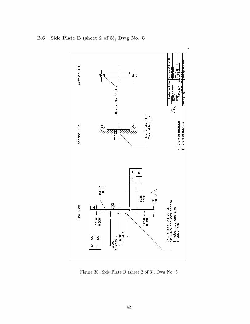
B.6 Side Plate B (sheet 2 of 3), Dwg No. 5
Figure 30: Side Plate B (sheet 2 of 3), Dwg No. 5
42
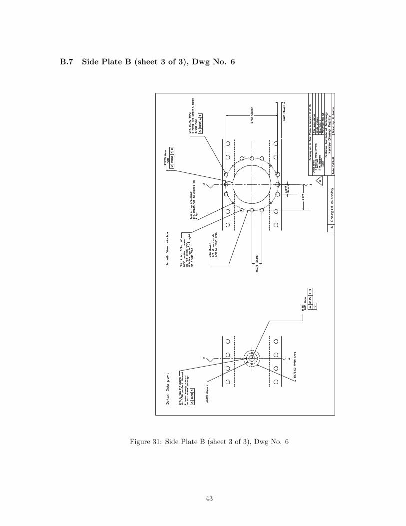
B.7 Side Plate B (sheet 3 of 3), Dwg No. 6
Figure 31: Side Plate B (sheet 3 of 3), Dwg No. 6
43
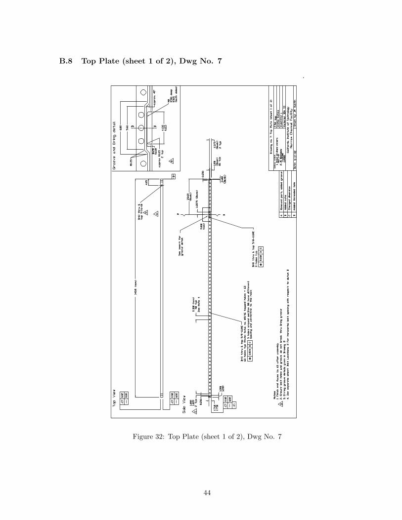
B.8 Top Plate (sheet 1 of 2), Dwg No. 7
Figure 32: Top Plate (sheet 1 of 2), Dwg No. 7
44
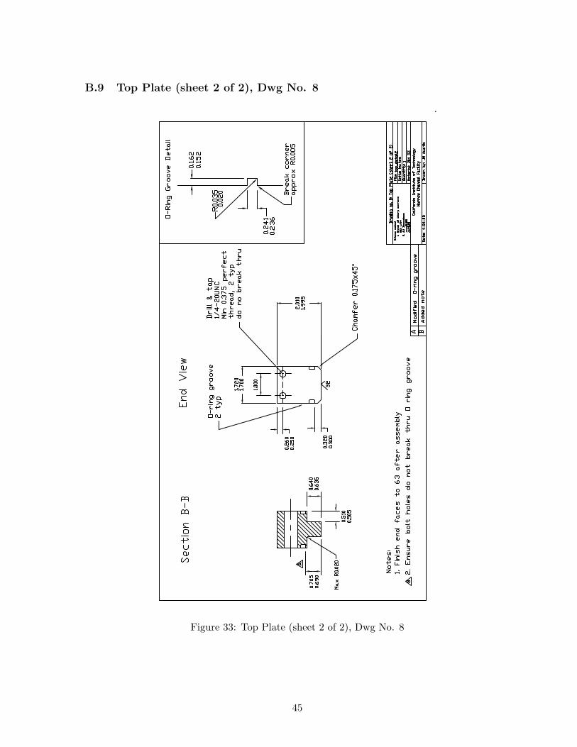
B.9 Top Plate (sheet 2 of 2), Dwg No. 8
Figure 33: Top Plate (sheet 2 of 2), Dwg No. 8
45
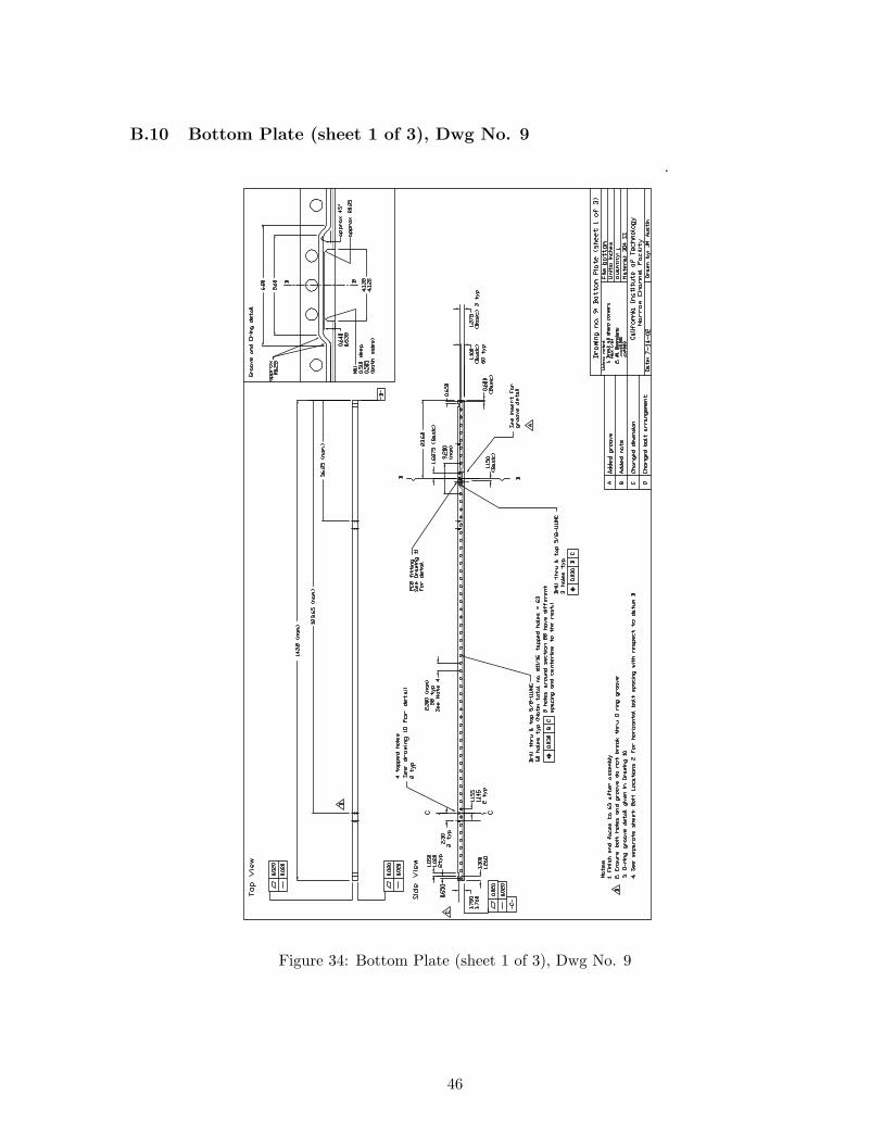
B.10 Bottom Plate (sheet 1 of 3), Dwg No. 9
Figure 34: Bottom Plate (sheet 1 of 3), Dwg No. 9
46
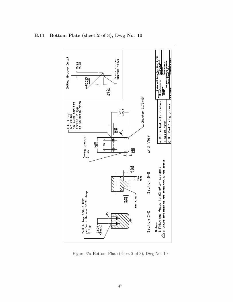
B.11 Bottom Plate (sheet 2 of 3), Dwg No. 10
Figure 35: Bottom Plate (sheet 2 of 3), Dwg No. 10
47
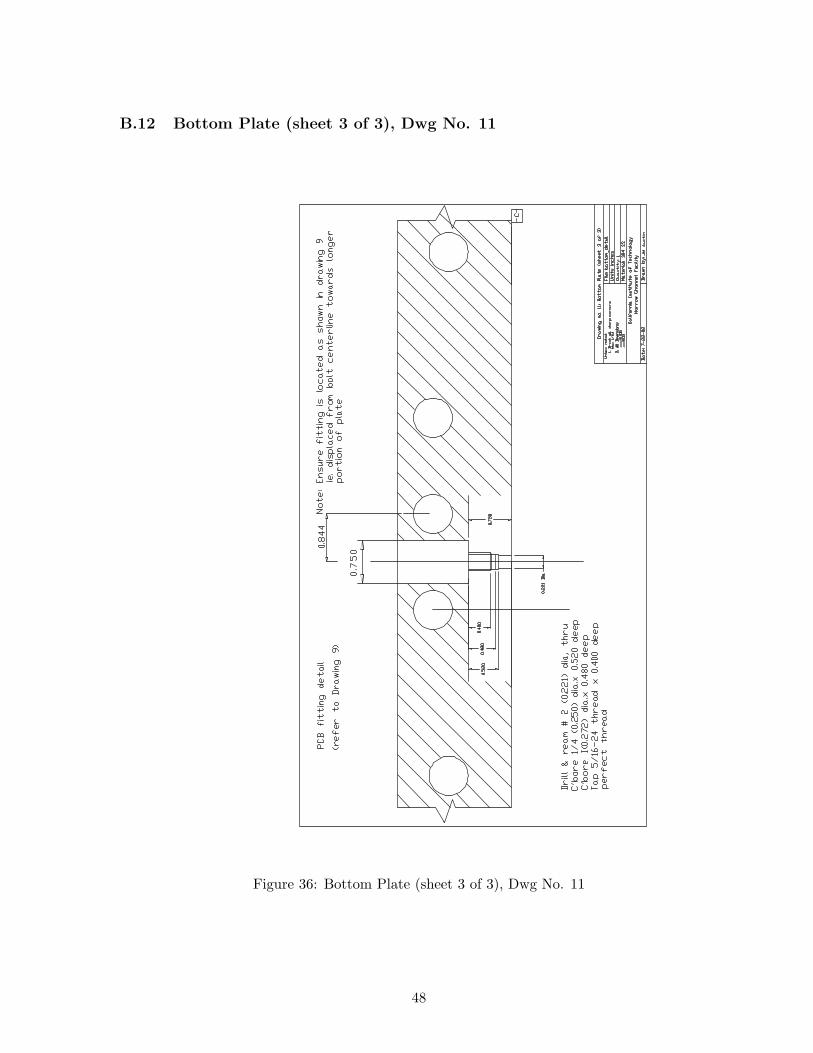
B.12 Bottom Plate (sheet 3 of 3), Dwg No. 11
Figure 36: Bottom Plate (sheet 3 of 3), Dwg No. 11
48
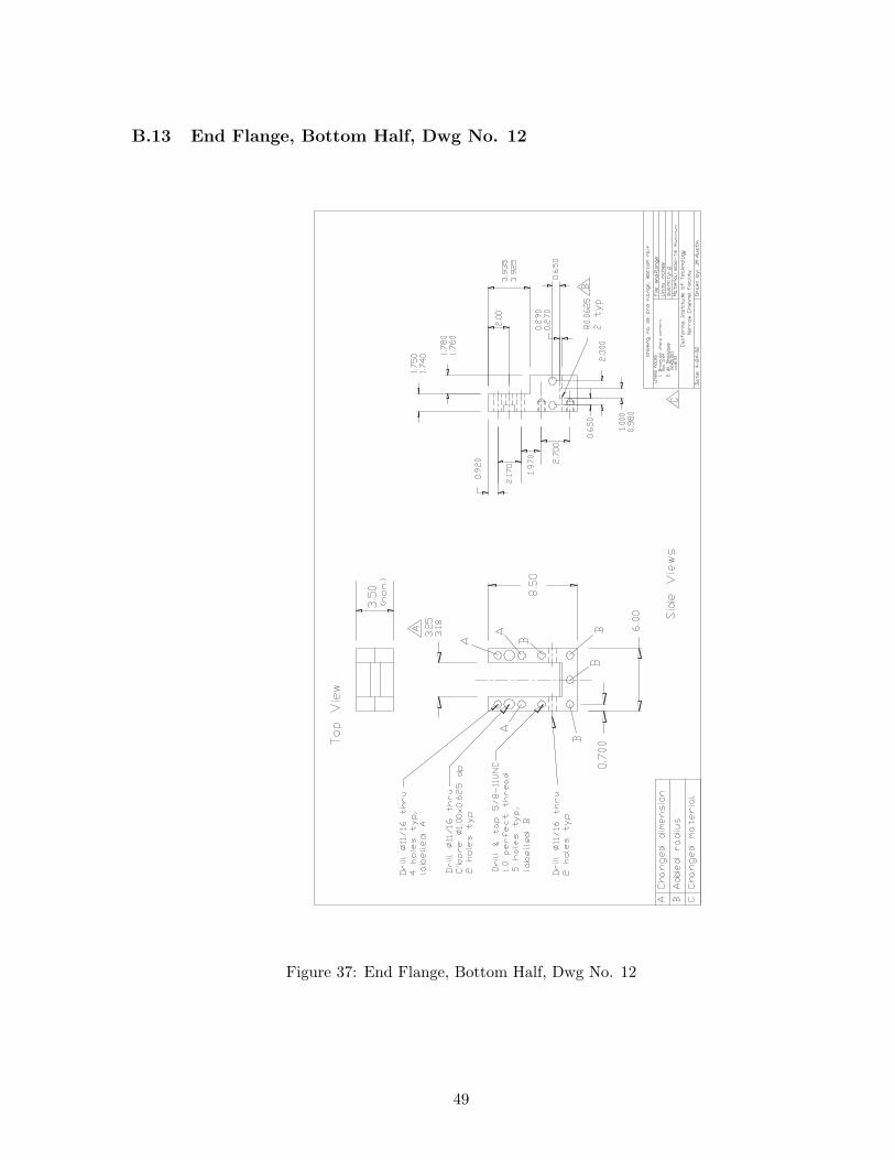
B.13 End Flange, Bottom Half, Dwg No. 12
Figure 37: End Flange, Bottom Half, Dwg No. 12
49
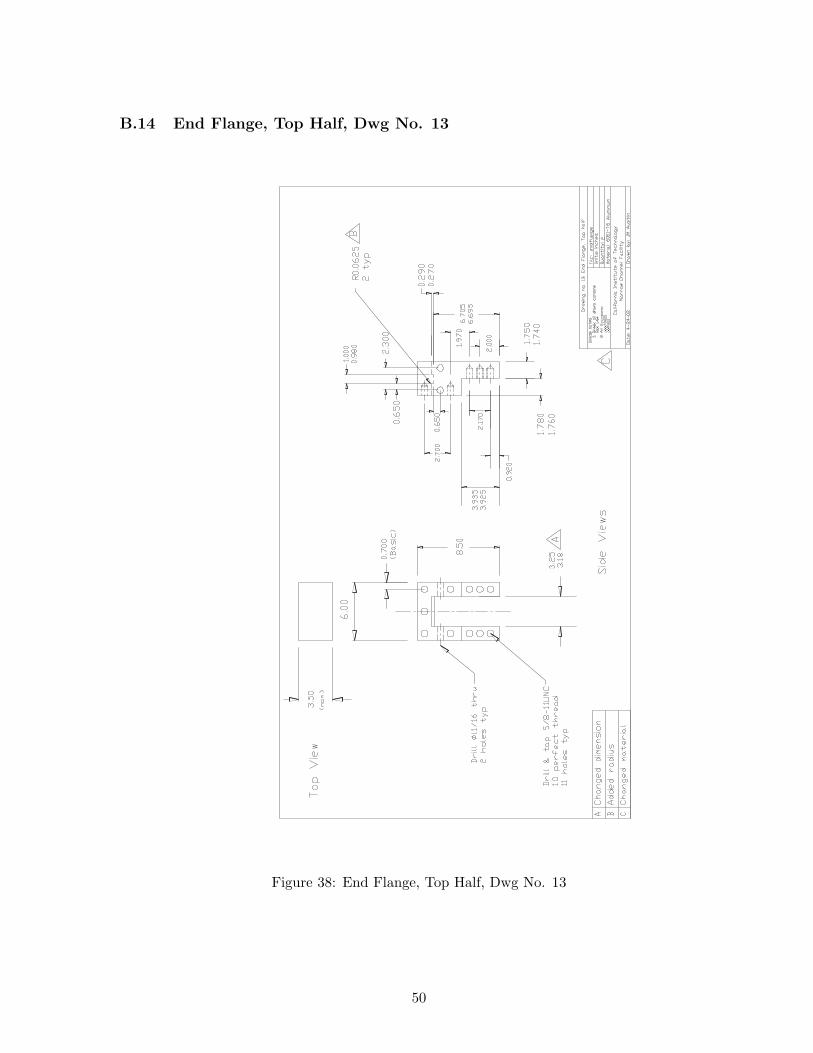
B.14 End Flange, Top Half, Dwg No. 13
Figure 38: End Flange, Top Half, Dwg No. 13
50
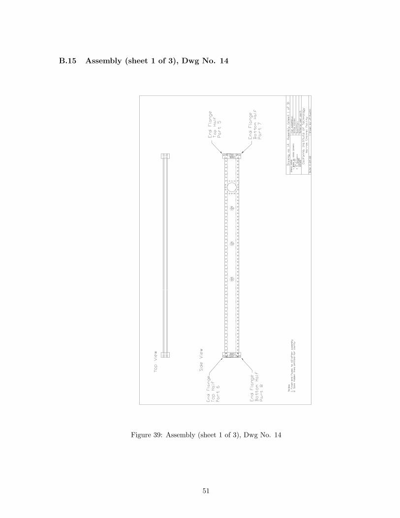
B.15 Assembly (sheet 1 of 3), Dwg No. 14
Figure 39: Assembly (sheet 1 of 3), Dwg No. 14
51
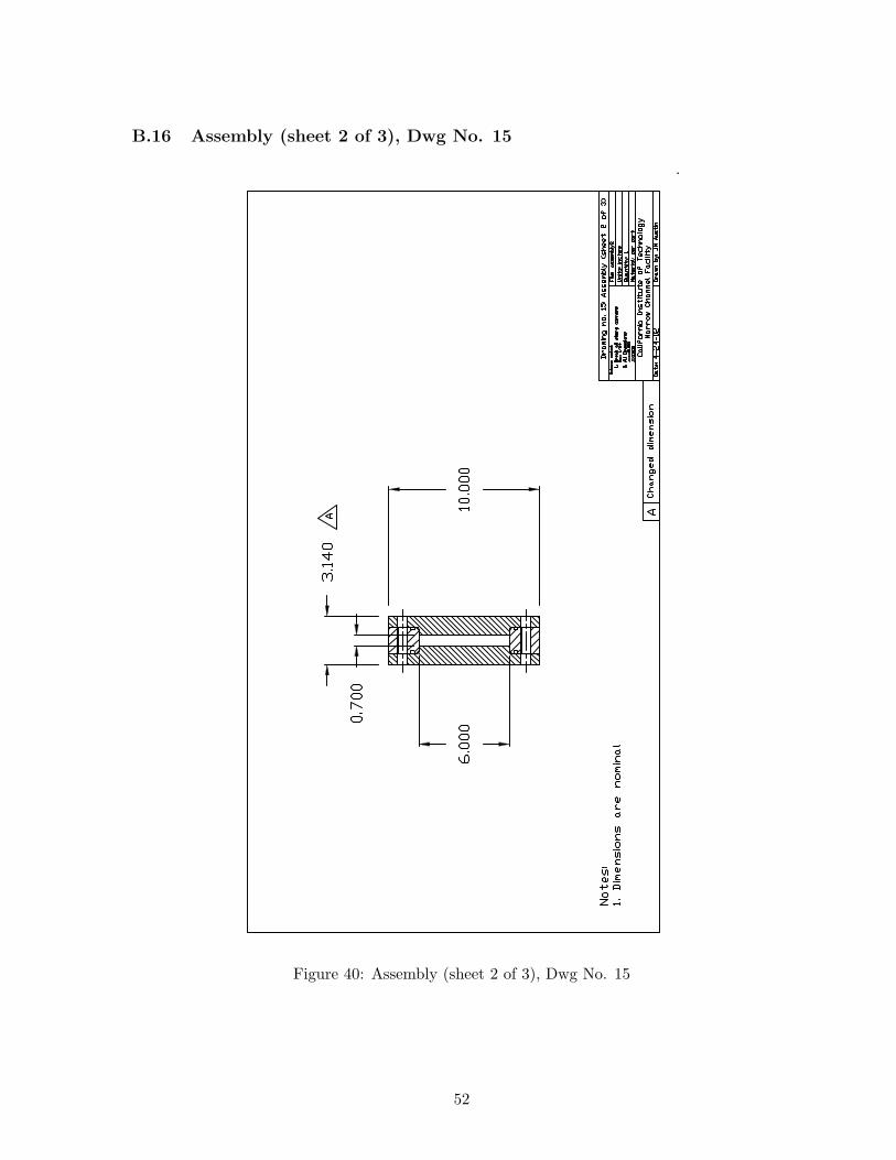
B.16 Assembly (sheet 2 of 3), Dwg No. 15
Figure 40: Assembly (sheet 2 of 3), Dwg No. 15
52
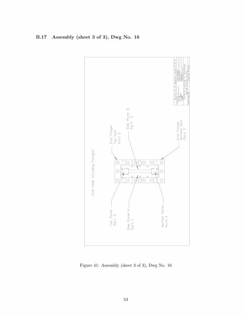
B.17 Assembly (sheet 3 of 3), Dwg No. 16
Figure 41: Assembly (sheet 3 of 3), Dwg No. 16
53
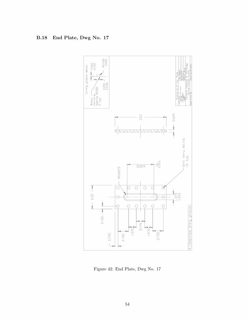
B.18 End Plate, Dwg No. 17
Figure 42: End Plate, Dwg No. 17
54
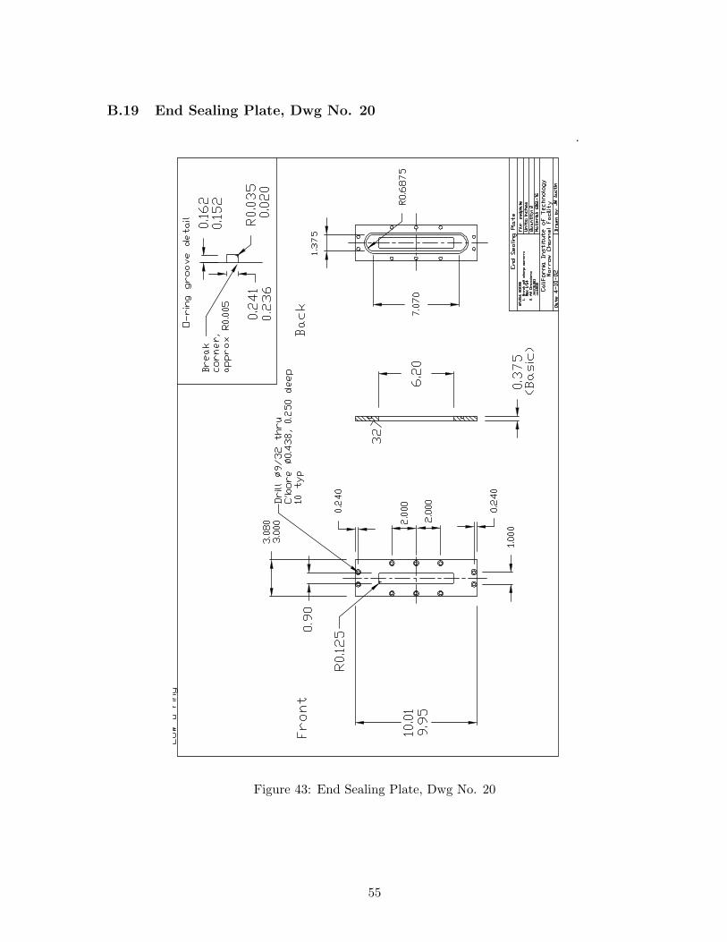
B.19 End Sealing Plate, Dwg No. 20
Figure 43: End Sealing Plate, Dwg No. 20
55
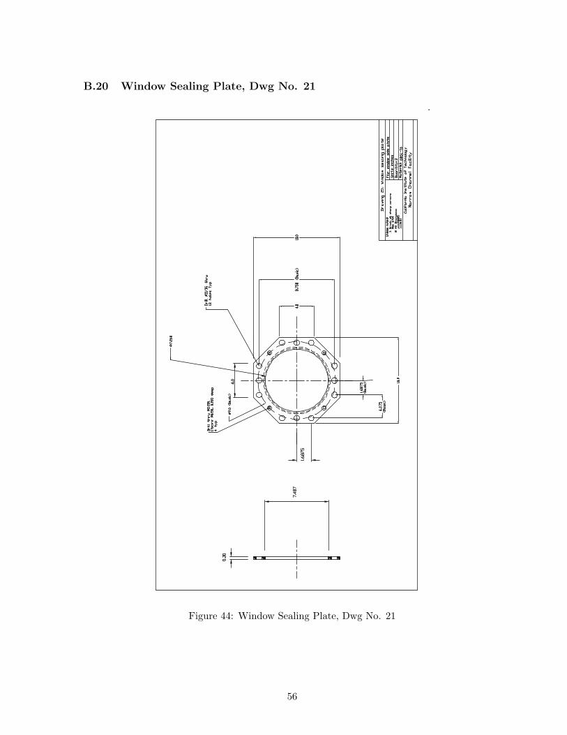
B.20 Window Sealing Plate, Dwg No. 21
Figure 44: Window Sealing Plate, Dwg No. 21
56

C Narrow Channel Planar Detonation Initiator Drawings
57
C.1 Planar Initiator Assembly, Dwg No. 1
A AA
-A (
1 :
3.5
)
21
1
initia
tor
ass
em
bly
.sld
drw
pe
r p
art
Ca
lifo
rnia
In
stitu
te o
f Te
ch
no
log
yG
ALC
IT E
xp
losi
on
Dyn
am
ics
Lab
ora
tory
8-1
3-2
002
Pla
na
r In
itia
tor
Ass
em
bly
ITEM
NO
.Q
TY.
PA
RT
NO
.D
ESC
RIP
TIO
N
11
pla
na
r in
itia
tor
21
co
ve
r p
late
DA
TE:
DR
AW
N B
Y:
QU
AN
TITY
:U
NIT
S:
MA
TER
IAL:
FIL
E:
UN
LESS N
OTE
D:
M. G
run
tha
ne
r
1In
ch
es
1. B
rea
k S
ha
rp C
orn
ers
Ma
x 1/6
4
2. A
ll D
ime
nsi
on
s:
.xx
x0.0
05
.xx
0.0
3
3. D
raw
ing
no
t to
sc
ale
DW
G #
:
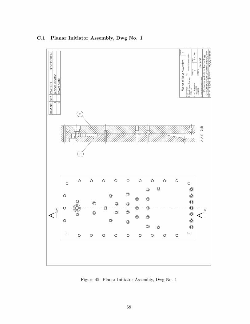
Figure 45: Planar Initiator Assembly, Dwg No. 1
58
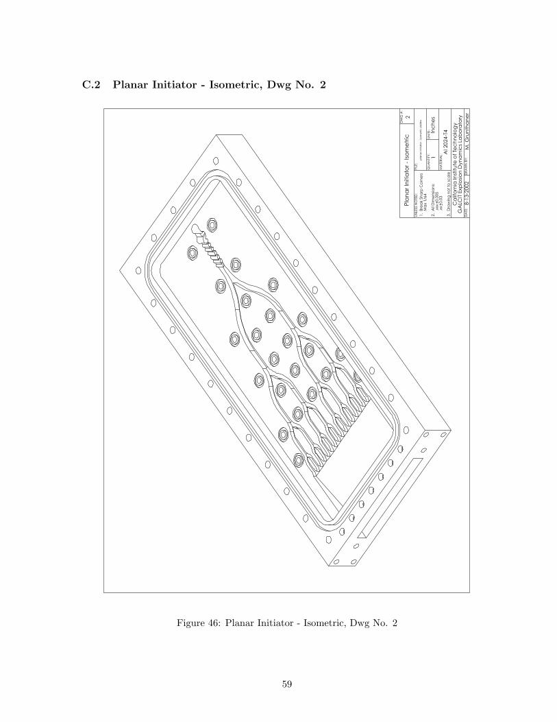
C.2 Planar Initiator - Isometric, Dwg No. 2
Pla
na
r In
itia
tor
- Is
om
etr
ic
8-1
3-2
002
Ca
lifo
rnia
In
stitu
te o
f Te
ch
no
log
yG
ALC
IT E
xp
losi
on
Dyn
am
ics
Lab
ora
tory
Al 2024-T
4
pla
na
r in
itia
tor
- is
om
etr
ic.s
ldd
rw
2
DA
TE:
DR
AW
N B
Y:
QU
AN
TITY
:U
NIT
S:
MA
TER
IAL:
FIL
E:
UN
LESS N
OTE
D:
M. G
run
tha
ne
r
1In
ch
es
1. B
rea
k S
ha
rp C
orn
ers
Ma
x 1/6
4
2. A
ll D
ime
nsi
on
s:
.xx
x0.0
05
.xx
0.0
3
3. D
raw
ing
no
t to
sc
ale
DW
G #
:
Figure 46: Planar Initiator - Isometric, Dwg No. 2
59
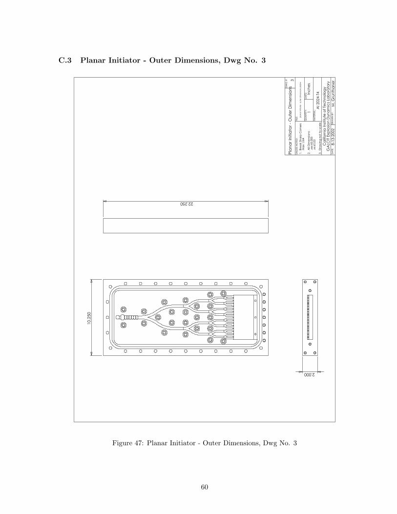
C.3 Planar Initiator - Outer Dimensions, Dwg No. 3
10.2
50
2.000
22.250
Pla
na
r In
itia
tor
- O
ute
r D
ime
nsi
on
s
8-1
3-2
002
Ca
lifo
rnia
In
stitu
te o
f Te
ch
no
log
yG
ALC
IT E
xp
losi
on
Dyn
am
ics
Lab
ora
tory
Al 2024-T
4
pla
na
r in
itia
tor
- o
ute
r d
ime
nsi
on
s.sl
dd
rw
3
DA
TE:
DR
AW
N B
Y:
QU
AN
TITY
:U
NIT
S:
MA
TER
IAL:
FIL
E:
UN
LESS N
OTE
D:
M. G
run
tha
ne
r
1In
ch
es
1. B
rea
k S
ha
rp C
orn
ers
Ma
x 1/6
4
2. A
ll D
ime
nsi
on
s:
.xx
x0.0
05
.xx
0.0
3
3. D
raw
ing
no
t to
sc
ale
DW
G #
:
Figure 47: Planar Initiator - Outer Dimensions, Dwg No. 3
60
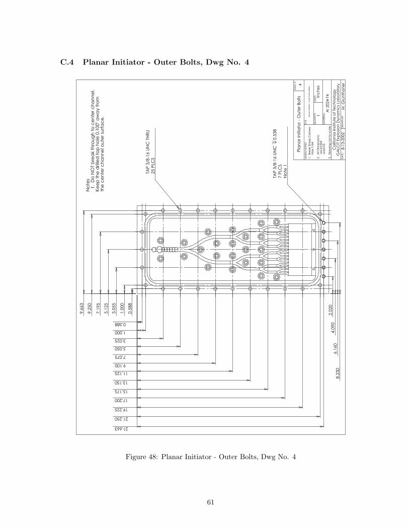
C.4 Planar Initiator - Outer Bolts, Dwg No. 4
0.5
88
1.0
00
3.0
55
5.1
25
7.1
95
9.2
50
0.588
1.000
5.050
7.075
9.100
11.125
13.150
15.175
17.200
19.225
21.250
21.663
3.025
9.6
63
25 P
LCS
TAP
3/8
-16 U
NC
TH
RU
7 P
LCS
No
te 1
TAP
3/8
-16 U
NC
0.5
38
2.0
20
4.0
90
6.1
60
8.2
30
No
tes
1. D
o N
OT
bre
ak t
hro
ug
h t
o c
en
ter
ch
an
ne
l.K
ee
p t
he
drille
d t
ap
ho
le 0
.100
" a
wa
y f
rom
the
ce
nte
r c
ha
nn
el o
ute
r su
rfa
ce
.
4
pla
na
r in
itia
tor
- o
ute
r b
olts.
sld
drw
Al 2024-T
4
Ca
lifo
rnia
In
stitu
te o
f Te
ch
no
log
yG
ALC
IT E
xp
losi
on
Dyn
am
ics
Lab
ora
tory
8-1
3-2
002
Pla
na
r In
itia
tor
- O
ute
r B
olts
DA
TE:
DR
AW
N B
Y:
QU
AN
TITY
:U
NIT
S:
MA
TER
IAL:
FIL
E:
UN
LESS N
OTE
D:
M. G
run
tha
ne
r
1In
ch
es
1. B
rea
k S
ha
rp C
orn
ers
Ma
x 1/6
4
2. A
ll D
ime
nsi
on
s:
.xx
x0.0
05
.xx
0.0
3
3. D
raw
ing
no
t to
sc
ale
DW
G #
:
Figure 48: Planar Initiator - Outer Bolts, Dwg No. 4
61
C.5 Planar Initiator - Outer O-Ring, Dwg No. 5
20.508
8.5
08
0.8
71
0.871
R1.5
62
AA
B
A-A
(1 :
4)
0.3
12
0.206
B (
2 : 1
)
OU
TER
O-R
ING
GR
OO
VE D
ETA
ILP
AR
KER
STA
TIC
O-R
ING
P 2
-463
5
pla
na
r in
itia
tor
- o
ute
r o
-rin
g.s
ldd
rw
Al 2024-T
4
Ca
lifo
rnia
In
stitu
te o
f Te
ch
no
log
yG
ALC
IT E
xp
losi
on
Dyn
am
ics
Lab
ora
tory
8-1
3-2
002
Pla
na
r In
itia
tor
- O
ute
r O
-Rin
g
BR
EA
K C
OR
NER
S A
PP
RO
X. R
0.0
05
MA
X R
AD
IUS R
0.0
35
63
16
DA
TE:
DR
AW
N B
Y:
QU
AN
TITY
:U
NIT
S:
MA
TER
IAL:
FIL
E:
UN
LESS N
OTE
D:
M. G
run
tha
ne
r
1In
ch
es
1. B
rea
k S
ha
rp C
orn
ers
Ma
x 1/6
4
2. A
ll D
ime
nsi
on
s:
.xx
x0.0
05
.xx
0.0
3
3. D
raw
ing
no
t to
sc
ale
DW
G #
:
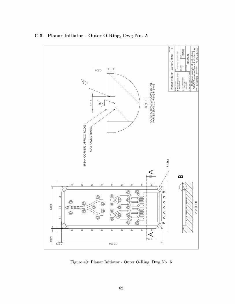
Figure 49: Planar Initiator - Outer O-Ring, Dwg No. 5
62
C.6 Planar Initiator - Bath Tub, Dwg No. 6
1.500 19.2500.000
+0.0051.5
00
7.2
50
0.0
00
+0.0
05
R0.6
25
AA
0.650-0.002
0.000
A-A
(1 :
4)
6
pla
na
r in
itia
tor
- b
ath
tu
b.s
ldd
rw
Al 2024-T
4
Ca
lifo
rnia
In
stitu
te o
f Te
ch
no
log
yG
ALC
IT E
xp
losi
on
Dyn
am
ics
Lab
ora
tory
8-1
3-2
002
Pla
na
r In
itia
tor
- B
ath
Tu
b
MA
X R
AD
IUS R
0.0
05 A
RO
UN
D B
ATH
TUB
DA
TE:
DR
AW
N B
Y:
QU
AN
TITY
:U
NIT
S:
MA
TER
IAL:
FIL
E:
UN
LESS N
OTE
D:
M. G
run
tha
ne
r
1In
ch
es
1. B
rea
k S
ha
rp C
orn
ers
Ma
x 1/6
4
2. A
ll D
ime
nsi
on
s:
.xx
x0.0
05
.xx
0.0
3
3. D
raw
ing
no
t to
sc
ale
DW
G #
:
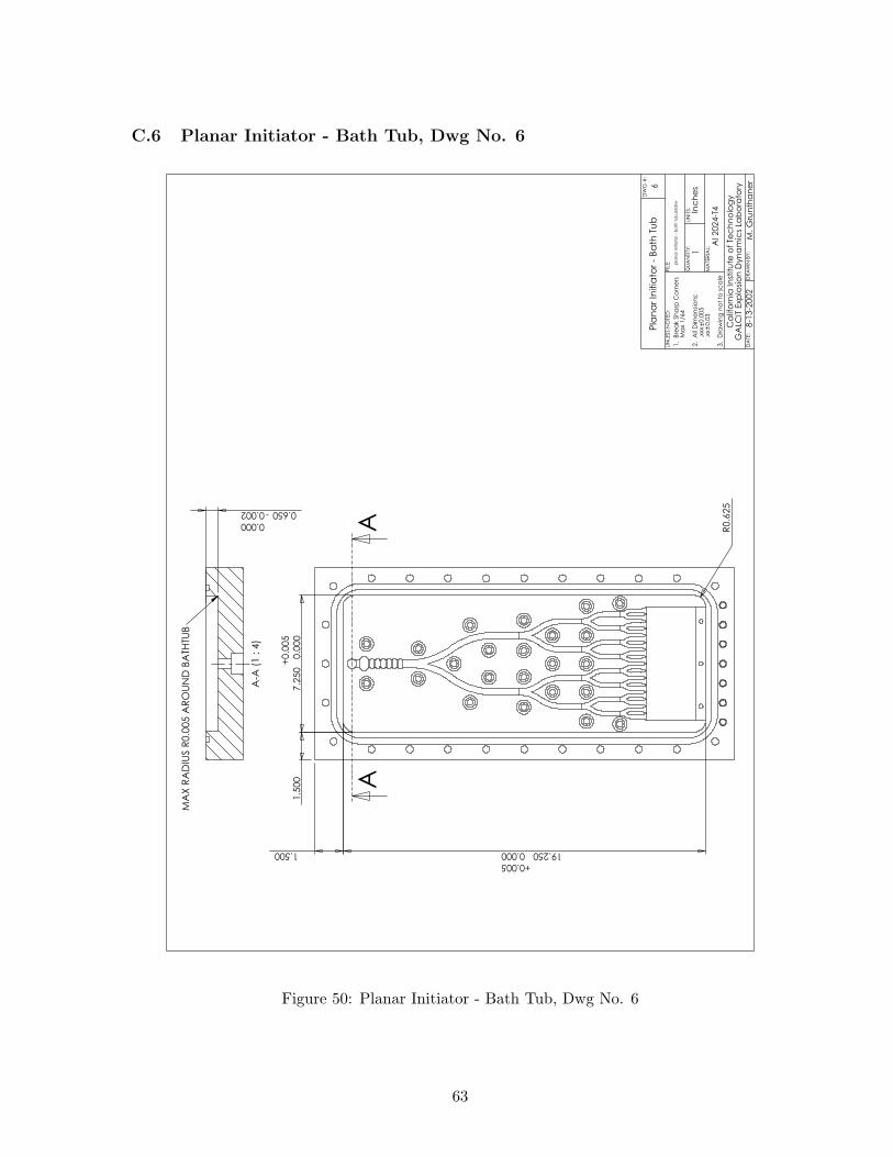
Figure 50: Planar Initiator - Bath Tub, Dwg No. 6
63
C.7 Planar Initiator - Inner Bolts, Dwg No. 7
4.0
75
4.3
25
3.0
75
4.4
00
2.8
25
3.6
25
2.0
75
1.9
25
4.4
25
3.6
25
2.750
5.500
8.250
11.100
12.625
14.425
16.200
7.400
10.2
50
23 P
LCS
TAP
5/1
6-1
8 U
NC
TH
RU
6.1
75
5.9
25
5.1
25
7.1
75
5.8
50
5.8
25
7.4
25
5.1
25
6.6
25
5.1
25
6.6
25
8.1
75
8.3
25
A A
7
pla
na
r in
itia
tor
- in
ne
r b
olts.
sld
drw
Al 2024-T
4
Ca
lifo
rnia
In
stitu
te o
f Te
ch
no
log
yG
ALC
IT E
xp
losi
on
Dyn
am
ics
Lab
ora
tory
8-1
3-2
002
Pla
na
r In
itia
tor
- In
ne
r B
olts
B
A-A
(1 :
3)
0.122
0.0
77
B (
4 : 1
)
BO
LT O
-RIN
G G
RO
OV
E D
ETA
ILP
AR
KER
STA
TIC
O-R
ING
P 2
-113
BR
EA
K C
OR
NER
SA
PP
RO
X. R
0.0
05
MA
X R
AD
IUS R
0.0
15
63
16
DA
TE:
DR
AW
N B
Y:
QU
AN
TITY
:U
NIT
S:
MA
TER
IAL:
FIL
E:
UN
LESS N
OTE
D:
M. G
run
tha
ne
r
1In
ch
es
1. B
rea
k S
ha
rp C
orn
ers
Ma
x 1/6
4
2. A
ll D
ime
nsi
on
s:
.xx
x0.0
05
.xx
0.0
3
3. D
raw
ing
no
t to
sc
ale
DW
G #
:
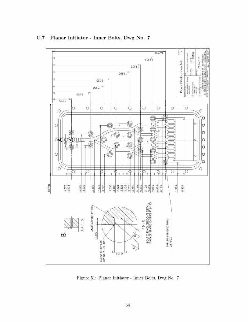
Figure 51: Planar Initiator - Inner Bolts, Dwg No. 7
64
C.8 Planar Initiator - Cutting Path, Dwg No. 8
0.4
00
0.4
00
0.4
00
0.3
36
0.5
00
0.5
00
0.2
50
0.5
00
0.3
36
0.3
36
0.2
83
0.2
83
0.2
38
0.2
38
0.2
00
0.2
00
8
pla
na
r in
itia
tor
- p
ath
wa
ys.
sld
drw
Al 2024-T
4
Ca
lifo
rnia
In
stitu
te o
f Te
ch
no
log
yG
ALC
IT E
xp
losi
on
Dyn
am
ics
Lab
ora
tory
8-1
3-2
002
Pla
na
r In
itia
tor
- C
utt
ing
Pa
th
DA
TE:
DR
AW
N B
Y:
QU
AN
TITY
:U
NIT
S:
MA
TER
IAL:
FIL
E:
UN
LESS N
OTE
D:
M. G
run
tha
ne
r
1In
ch
es
1. B
rea
k S
ha
rp C
orn
ers
Ma
x 1/6
4
2. A
ll D
ime
nsi
on
s:
.xx
x0.0
05
.xx
0.0
3
3. D
raw
ing
no
t to
sc
ale
DW
G #
:
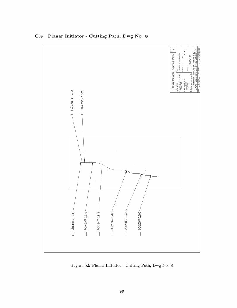
Figure 52: Planar Initiator - Cutting Path, Dwg No. 8
65
C.9 Planar Initiator - Channel Dimensions, Dwg No. 9
3.025 5.818 3.369 2.045 1.362
1.4
68
0.7
22
0.3
53
0.1
69
R3.6
47
R3.9
83
R1.7
89
R2.0
44
R0.8
67
R1.1
06
R0.4
11
R0.6
11
R0.5
58
6 P
LCS
0.2
50
0.5
00
0.5
00
0.5
00
0.5
00 T
HR
U
0.4530.300
0.647
0.2
83
0.2
50
9
pla
na
r in
itia
tor
- c
ha
nn
el d
ime
nsi
on
s.sl
dd
rw
Al 2024-T
4
Ca
lifo
rnia
In
stitu
te o
f Te
ch
no
log
yG
ALC
IT E
xp
losi
on
Dyn
am
ics
Lab
ora
tory
8-1
3-2
002
Pla
na
r In
itia
tor
- C
ha
nn
el D
ime
nsi
on
s
DA
TE:
DR
AW
N B
Y:
QU
AN
TITY
:U
NIT
S:
MA
TER
IAL:
FIL
E:
UN
LESS N
OTE
D:
M. G
run
tha
ne
r
1In
ch
es
1. B
rea
k S
ha
rp C
orn
ers
Ma
x 1/6
4
2. A
ll D
ime
nsi
on
s:
.xx
x0.0
05
.xx
0.0
3
3. D
raw
ing
no
t to
sc
ale
DW
G #
:
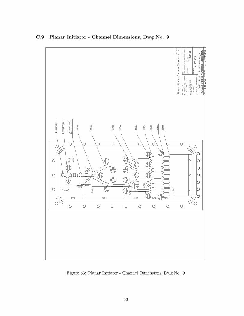
Figure 53: Planar Initiator - Channel Dimensions, Dwg No. 9
66
C.10 Planar Initiator - Exit Ramp, Dwg No. 10
1.750
2.8
75
5.1
25
7.3
75
A A
2.000
0.700
0.650
6.0
00
2.1
25
0.3
45
1.5
25
0.350
1.000
1.650
8.7
25 9
.90
5
6 P
LCS
No
te 2
TAP
5/1
6-1
8 U
NC
1.4
17
ma
x
No
tes
1. D
o n
ot
let
drille
d h
ole
fo
r ta
p p
en
etr
ate
in
to c
ha
nn
els
.
2. D
o n
ot
let
drille
d h
ole
fo
r ta
p e
xc
ee
d 1
.50"
de
pth
.
1.978
B
C
A-A
(1 :
4.5
)
0.2
00
0.7
00
2.000
0.6
50
1.500
1.750
B (
1 : 1
.5)
DR
ILL
.221 T
HR
U.2
50
.420
.272
.380
TAP
5/1
6-2
4 U
NF-2
B
0.3
00
3 P
LCS
10
pla
na
r in
itia
tor
- e
xit r
am
p.s
ldd
rw
Al 2
024
-T4
Ca
lifo
rnia
In
stitu
te o
f Te
ch
no
log
yG
ALC
IT E
xp
losi
on
Dyn
am
ics
Lab
ora
tory
8-1
3-2
002
Pla
na
r In
itia
tor
- Exit R
am
p
C (
1 : 1
.5)
DR
ILL
.500 T
HR
U1
.53
min
.005
FO
R S
UR
FA
CE F
INIS
HTA
P 1
-1/1
6-1
2 U
NF
0.5
70
No
te 1
32
DA
TE:
DR
AW
N B
Y:
QU
AN
TITY
:U
NIT
S:
MA
TER
IAL:
FIL
E:
UN
LESS N
OTE
D:
M. G
run
tha
ne
r
1In
ch
es
1. B
rea
k S
ha
rp C
orn
ers
Ma
x 1/6
4
2. A
ll D
ime
nsi
on
s:
.xx
x0.0
05
.xx
0.0
3
3. D
raw
ing
no
t to
sc
ale
DW
G #
:
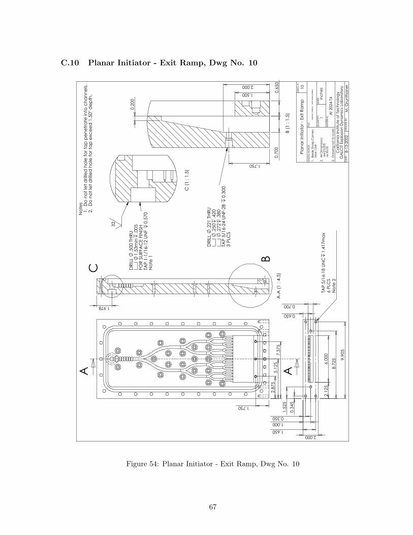
Figure 54: Planar Initiator - Exit Ramp, Dwg No. 10
67
C.11 Cover Plate - Isometric, Dwg No. 11
Co
ve
r P
late
- Iso
me
tric
8-1
3-2
002
Ca
lifo
rnia
In
stitu
te o
f Te
ch
no
log
yG
ALC
IT E
xp
losi
on
Dyn
am
ics
Lab
ora
tory
Al 2024-T
4
co
ve
r p
late
- iso
me
tric
.sld
drw
11
DA
TE:
DR
AW
N B
Y:
QU
AN
TITY
:U
NIT
S:
MA
TER
IAL:
FIL
E:
UN
LESS N
OTE
D:
M. G
run
tha
ne
r
1In
ch
es
1. B
rea
k S
ha
rp C
orn
ers
Ma
x 1/6
4
2. A
ll D
ime
nsi
on
s:
.xx
x0.0
05
.xx
0.0
3
3. D
raw
ing
no
t to
sc
ale
DW
G #
:
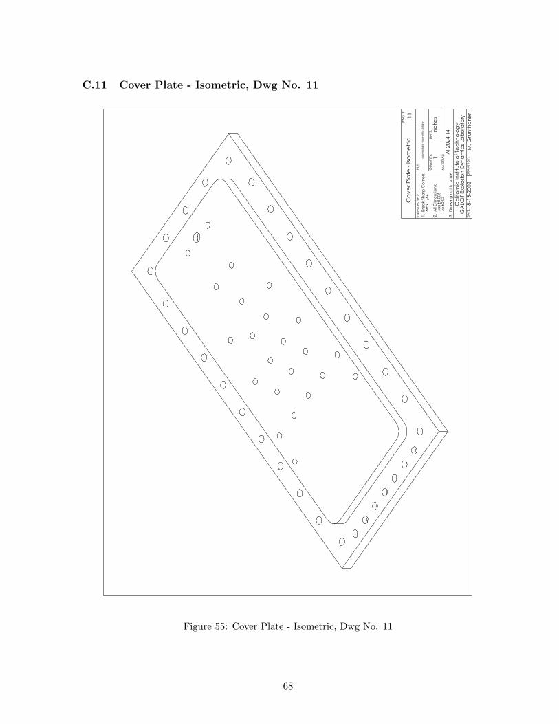
Figure 55: Cover Plate - Isometric, Dwg No. 11
68
C.12 Cover Plate - Outer Dimensions, Dwg No. 12
10.2
50
22.250 1.300
Co
ve
r P
late
- O
ute
r D
ime
nsi
on
s
8-1
3-2
002
Ca
lifo
rnia
In
stitu
te o
f Te
ch
no
log
yG
ALC
IT E
xp
losi
on
Dyn
am
ics
Lab
ora
tory
Al 2024-T
4
co
ve
r p
late
- o
ute
r d
ime
nsi
on
s.sl
dd
rw12
DA
TE:
DR
AW
N B
Y:
QU
AN
TITY
:U
NIT
S:
MA
TER
IAL:
FIL
E:
UN
LESS N
OTE
D:
M. G
run
tha
ne
r
1In
ch
es
1. B
rea
k S
ha
rp C
orn
ers
Ma
x 1/6
4
2. A
ll D
ime
nsi
on
s:
.xx
x0.0
05
.xx
0.0
3
3. D
raw
ing
no
t to
sc
ale
DW
G #
:
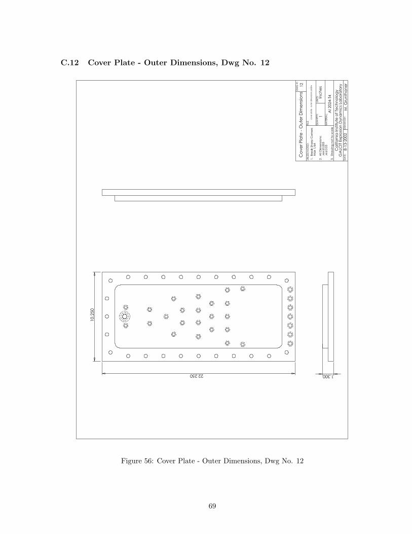
Figure 56: Cover Plate - Outer Dimensions, Dwg No. 12
69
C.13 Cover Plate - Outer Bolts, Dwg No. 13
0.5
88
1.0
00
3.0
55
5.1
25
7.1
95
9.2
50
9.6
63
0.588
1.000
3.025
5.050
7.075
9.100
11.125
13.150
15.175
17.200
19.225
21.250
25 P
LCS
3/8
BO
LT C
LEA
RA
NC
E T
HRU
21.663
2.0
20
4.0
90
6.1
60
8.2
30
C'B
OR
E F
AR
SID
E
0.3
75
7 P
LCS
3/8
BO
LT C
LEA
RA
NC
E T
HRU
C'B
OR
E F
AR
SID
E
0.8
00
23 P
LCS
5/1
6 B
OLT
CLE
AR
AN
CE
13
co
ve
r p
late
- o
ute
r b
olts.
sld
drw
Al 2024-T
4
Ca
lifo
rnia
In
stitu
te o
f Te
ch
no
log
yG
ALC
IT E
xp
losi
on
Dyn
am
ics
Lab
ora
tory
8-1
3-2
002
Co
ve
r P
late
- O
ute
r B
olts
DA
TE:
DR
AW
N B
Y:
QU
AN
TITY
:U
NIT
S:
MA
TER
IAL:
FIL
E:
UN
LESS N
OTE
D:
M. G
run
tha
ne
r
1In
ch
es
1. B
rea
k S
ha
rp C
orn
ers
Ma
x 1/6
4
2. A
ll D
ime
nsi
on
s:
.xx
x0.0
05
.xx
0.0
3
3. D
raw
ing
no
t to
sc
ale
DW
G #
:
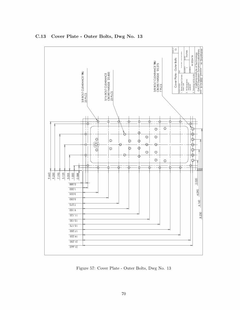
Figure 57: Cover Plate - Outer Bolts, Dwg No. 13
70
C.14 Cover Plate - Bath Tub, Dwg No. 14
1.5
05
7.2
40
-0.0
05
0.0
00
1.505 19.240-0.005
0.000
R0.6
20
32 0.6
09
0.0
00
+0.0
02
14
co
ve
r p
late
- b
ath
tu
b.s
ldd
rw
Al 2024-T
4
Ca
lifo
rnia
In
stitu
te o
f Te
ch
no
log
yG
ALC
IT E
xp
losi
on
Dyn
am
ics
Lab
ora
tory
8-1
3-2
002
Co
ve
r P
late
- B
ath
Tu
b
DA
TE:
DR
AW
N B
Y:
QU
AN
TITY
:U
NIT
S:
MA
TER
IAL:
FIL
E:
UN
LESS N
OTE
D:
M. G
run
tha
ne
r
1In
ch
es
1. B
rea
k S
ha
rp C
orn
ers
Ma
x 1/6
4
2. A
ll D
ime
nsi
on
s:
.xx
x0.0
05
.xx
0.0
3
3. D
raw
ing
no
t to
sc
ale
DW
G #
:
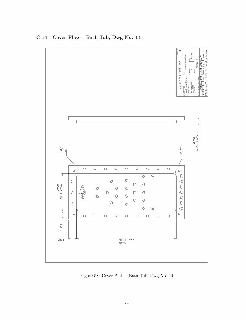
Figure 58: Cover Plate - Bath Tub, Dwg No. 14
71
C.15 Cover Plate - Inner Bolts, Dwg No. 15
4.0
75
4.3
25
3.0
75
4.4
00
2.8
25
3.6
25
4.4
25
2.0
75
1.9
25
2.750
5.500
7.400
8.250
9.250
11.100
12.625
14.425
16.200
6.1
75
5.9
25
5.1
25
7.1
75
5.8
50
3.6
25
5.1
25
6.6
25
8.1
75
8.3
25
5.1
25
6.6
25
5.8
25
7.4
25
10.2
50
C'B
OR
E F
AR
SID
E
0.8
00
23 P
LCS
5/1
6 B
OLT
CLE
AR
AN
CE T
HR
U
15
co
ve
r p
late
- in
ne
r b
olts.
sld
drw
Al 2024-T
4
Ca
lifo
rnia
In
stitu
te o
f Te
ch
no
log
yG
ALC
IT E
xp
losi
on
Dyn
am
ics
Lab
ora
tory
8-1
3-2
002
Co
ve
r P
late
- In
ne
r B
olts
DA
TE:
DR
AW
N B
Y:
QU
AN
TITY
:U
NIT
S:
MA
TER
IAL:
FIL
E:
UN
LESS N
OTE
D:
M. G
run
tha
ne
r
1In
ch
es
1. B
rea
k S
ha
rp C
orn
ers
Ma
x 1/6
4
2. A
ll D
ime
nsi
on
s:
.xx
x0.0
05
.xx
0.0
3
3. D
raw
ing
no
t to
sc
ale
DW
G #
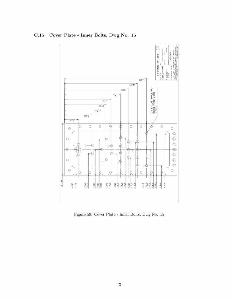
:
Figure 59: Cover Plate - Inner Bolts, Dwg No. 15
72
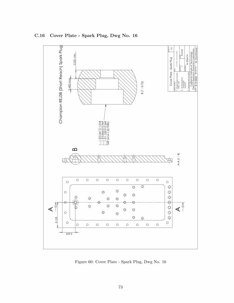
C.16 Cover Plate - Spark Plug, Dwg No. 16
5.1
25
2.625
A A
B
A-A
(1 :
4)
0.4
00
ma
x.
0.3
31
min
.
B (
1 : 0
.75)
0.5
61
1.0
18
0.8
66
0.9
69
1.2
20
0.5
69
TAP
M14-1
.25 T
HR
UCh
am
pio
n R
EJ3
8 (
Sh
ort
Re
ac
h)
Sp
ark
Plu
g
16
co
ve
r p
late
- s
pa
rk p
lug
.sld
drw
Al 2024-T
4
Ca
lifo
rnia
In
stitu
te o
f Te
ch
no
log
yG
ALC
IT E
xp
losi
on
Dyn
am
ics
Lab
ora
tory
8-1
3-2
002
Co
ve
r P
late
- S
pa
rk P
lug
DA
TE:
DR
AW
N B
Y:
QU
AN
TITY
:U
NIT
S:
MA
TER
IAL:
FIL
E:
UN
LESS N
OTE
D:
M. G
run
tha
ne
r
1In
ch
es
1. B
rea
k S
ha
rp C
orn
ers
Ma
x 1/6
4
2. A
ll D
ime
nsi
on
s:
.xx
x0.0
05
.xx
0.0
3
3. D
raw
ing
no
t to
sc
ale
DW
G #
:
Figure 60: Cover Plate - Spark Plug, Dwg No. 16
73

D Narrow Channel Detonation Tube Miscellaneous Documen-tation
74
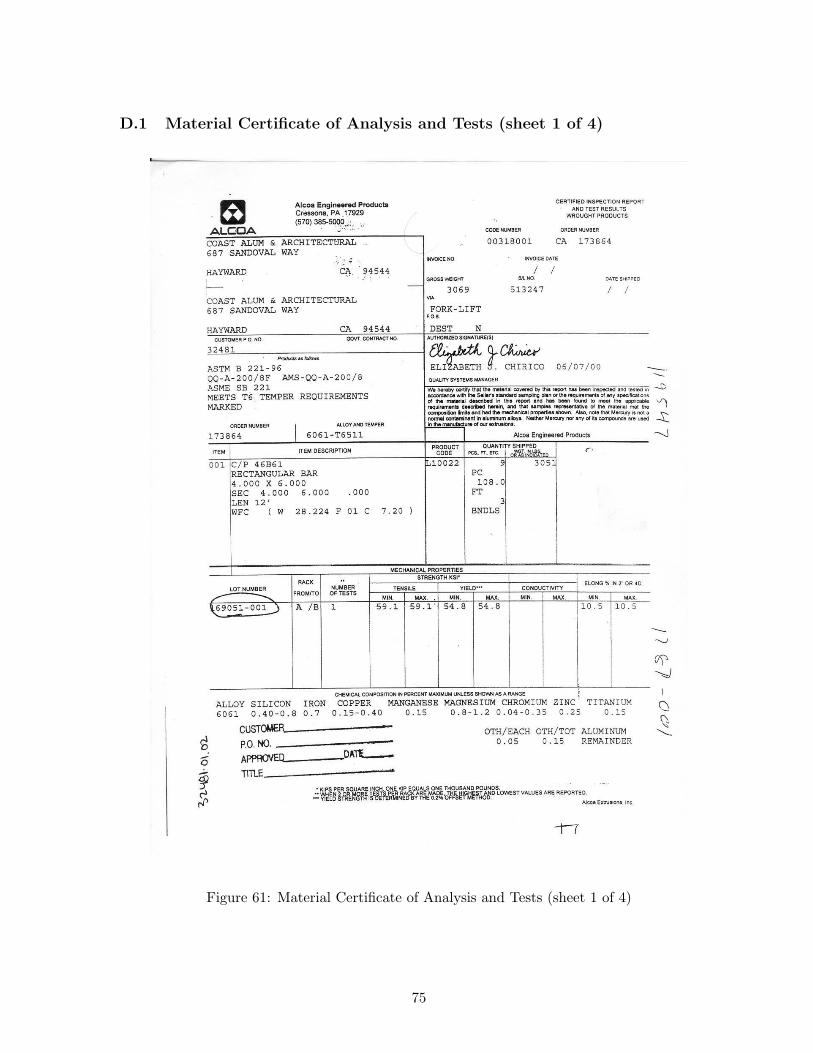
D.1 Material Certificate of Analysis and Tests (sheet 1 of 4)
Figure 61: Material Certificate of Analysis and Tests (sheet 1 of 4)
75
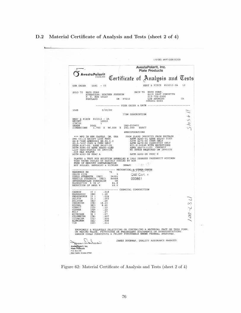
D.2 Material Certificate of Analysis and Tests (sheet 2 of 4)
Figure 62: Material Certificate of Analysis and Tests (sheet 2 of 4)
76
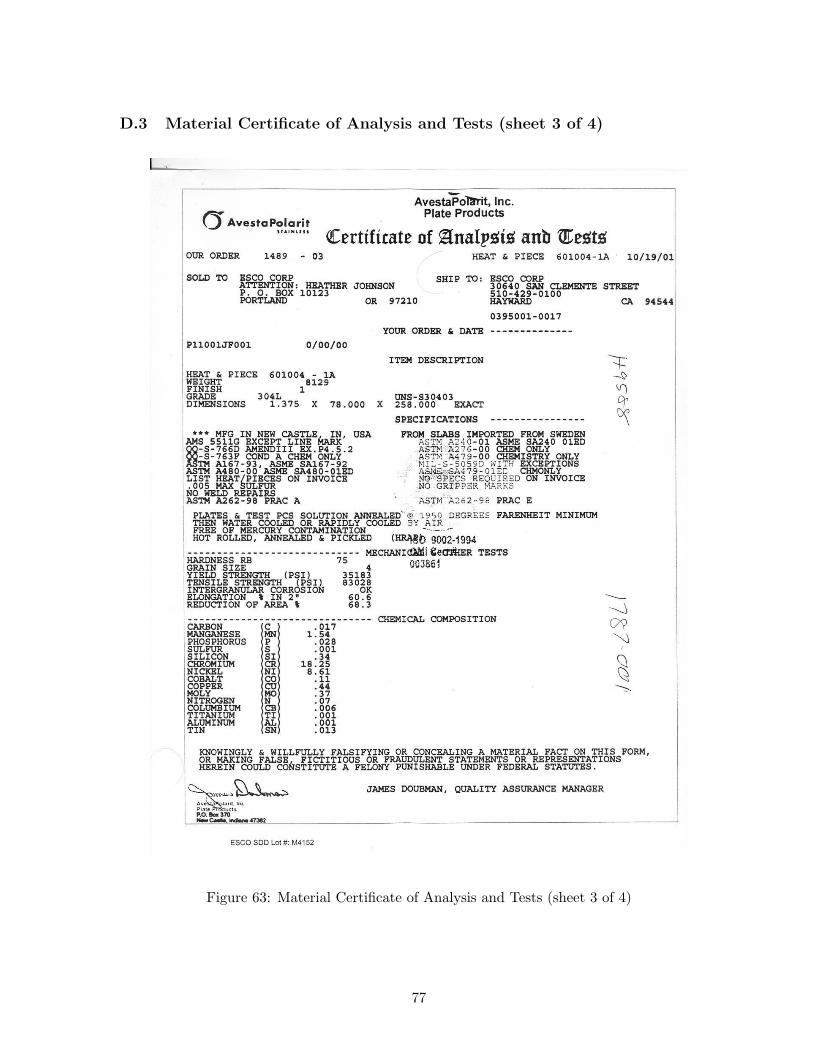
D.3 Material Certificate of Analysis and Tests (sheet 3 of 4)
Figure 63: Material Certificate of Analysis and Tests (sheet 3 of 4)
77
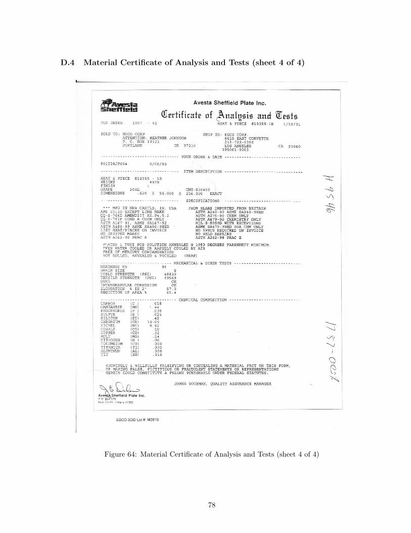
D.4 Material Certificate of Analysis and Tests (sheet 4 of 4)
Figure 64: Material Certificate of Analysis and Tests (sheet 4 of 4)
78
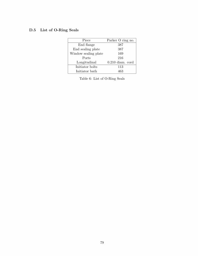
D.5 List of O-Ring Seals
Piece Parker O ring no.End flange 387
End sealing plate 387Window sealing plate 169
Ports 216Longitudinal 0.210 diam. cordInitiator bolts 113Initiator bath 463
Table 6: List of O-Ring Seals
79
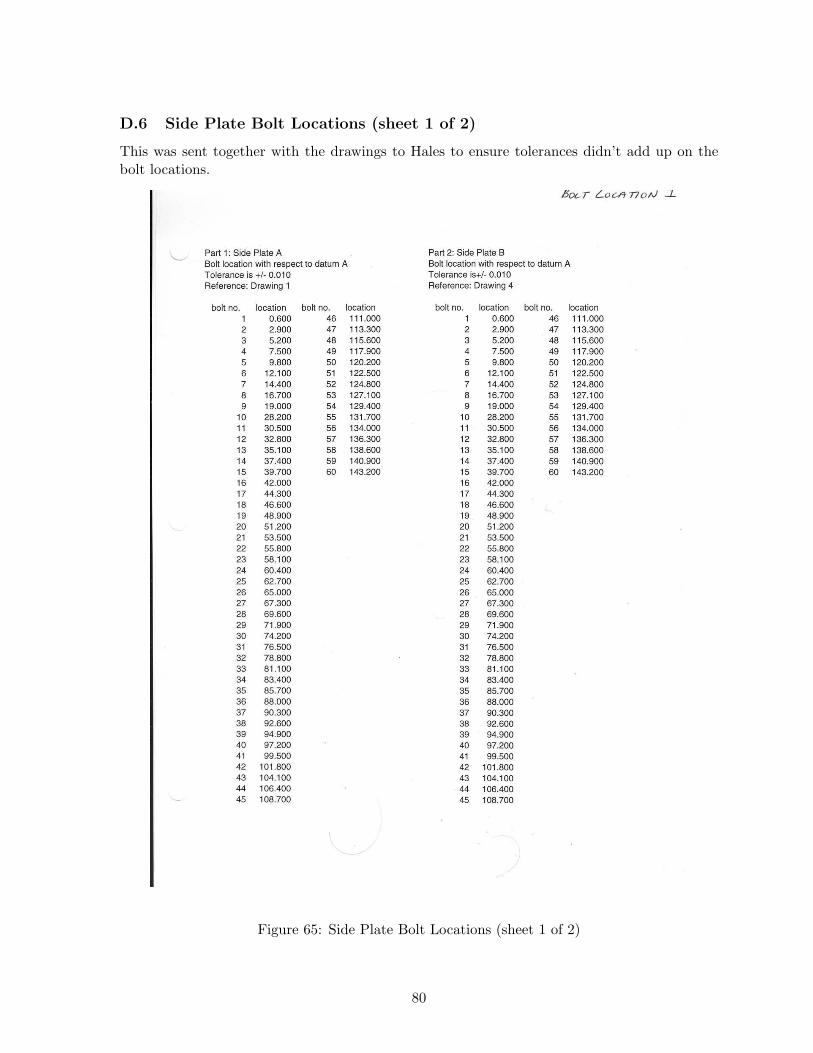
D.6 Side Plate Bolt Locations (sheet 1 of 2)
This was sent together with the drawings to Hales to ensure tolerances didn’t add up on thebolt locations.
Figure 65: Side Plate Bolt Locations (sheet 1 of 2)
80
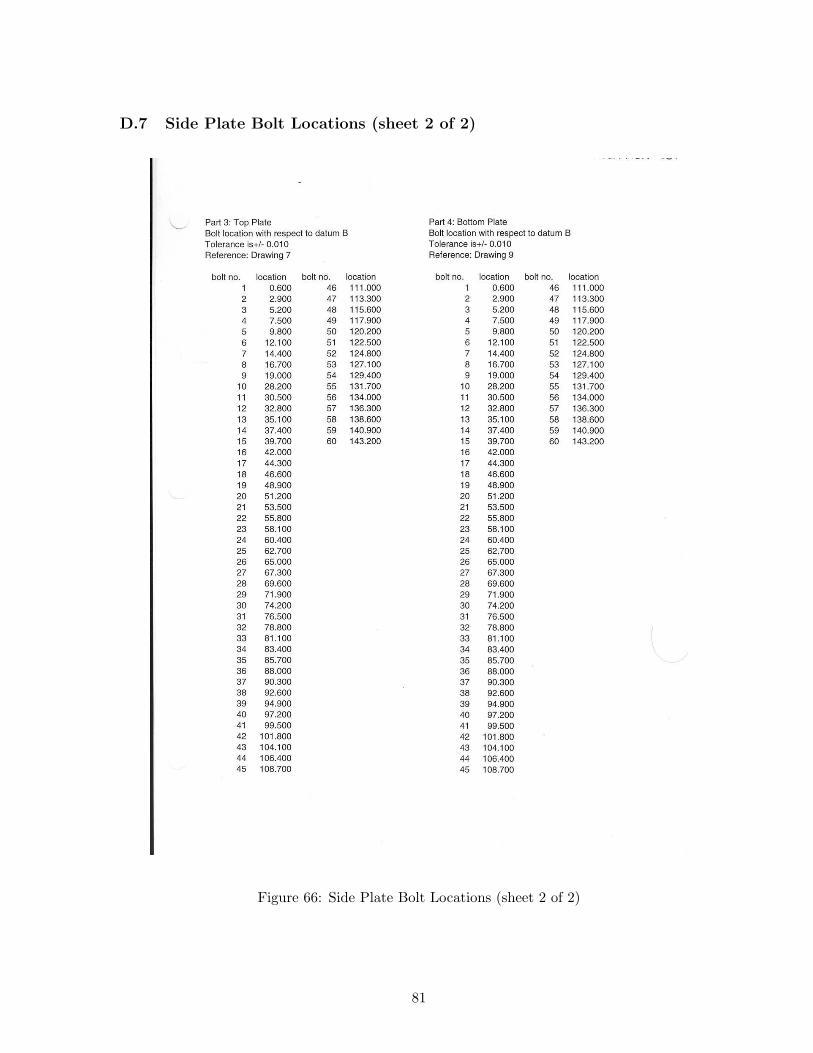
D.7 Side Plate Bolt Locations (sheet 2 of 2)
Figure 66: Side Plate Bolt Locations (sheet 2 of 2)
81
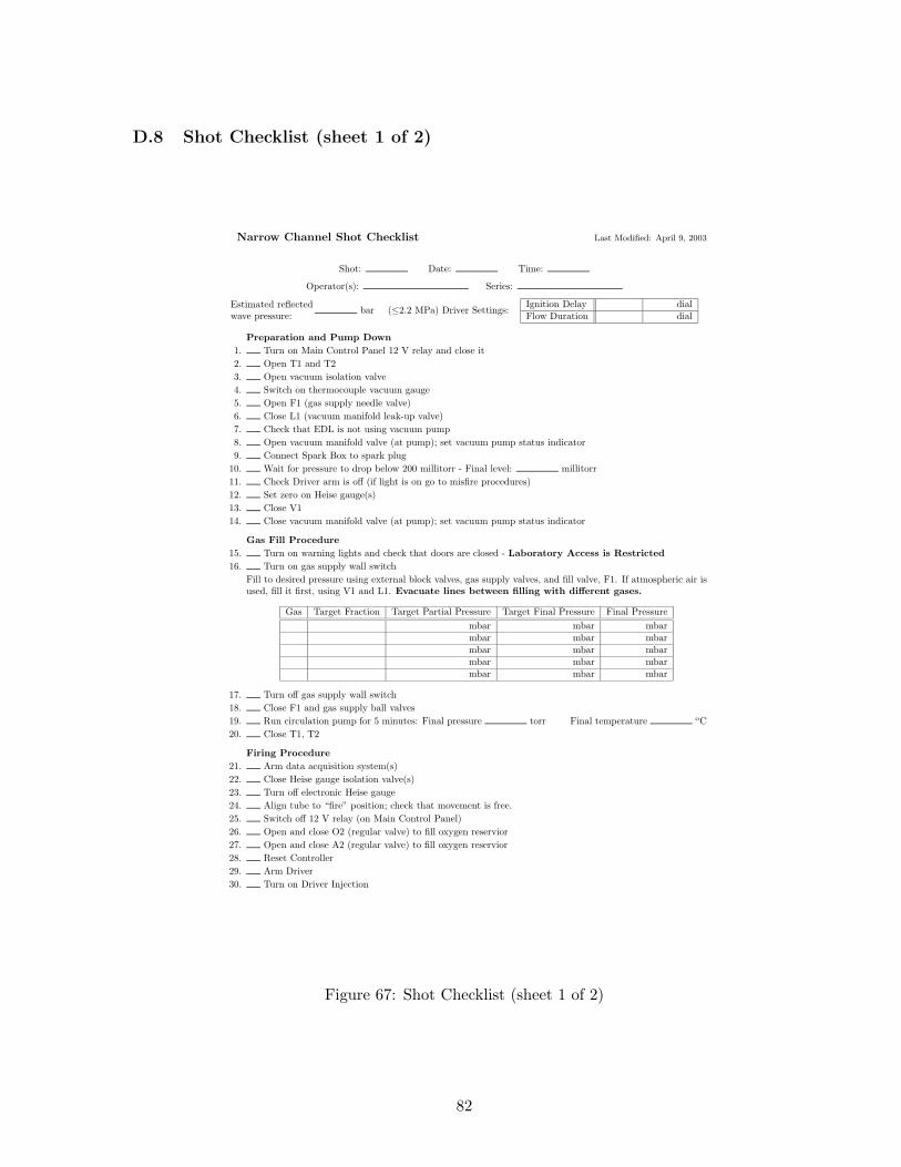
D.8 Shot Checklist (sheet 1 of 2)
Narrow Channel Shot Checklist Last Modified: April 9, 2003
Shot: Date: Time:
Operator(s): Series:
Estimated reflectedwave pressure: bar (≤2.2 MPa) Driver Settings:
Ignition Delay dialFlow Duration dial
Preparation and Pump Down1. Turn on Main Control Panel 12 V relay and close it2. Open T1 and T23. Open vacuum isolation valve4. Switch on thermocouple vacuum gauge5. Open F1 (gas supply needle valve)6. Close L1 (vacuum manifold leak-up valve)7. Check that EDL is not using vacuum pump8. Open vacuum manifold valve (at pump); set vacuum pump status indicator9. Connect Spark Box to spark plug
10. Wait for pressure to drop below 200 millitorr - Final level: millitorr11. Check Driver arm is off (if light is on go to misfire procedures)12. Set zero on Heise gauge(s)13. Close V114. Close vacuum manifold valve (at pump); set vacuum pump status indicator
Gas Fill Procedure15. Turn on warning lights and check that doors are closed - Laboratory Access is Restricted16. Turn on gas supply wall switch
Fill to desired pressure using external block valves, gas supply valves, and fill valve, F1. If atmospheric air isused, fill it first, using V1 and L1. Evacuate lines between filling with different gases.
Gas Target Fraction Target Partial Pressure Target Final Pressure Final Pressurembar mbar mbarmbar mbar mbarmbar mbar mbarmbar mbar mbarmbar mbar mbar
17. Turn off gas supply wall switch18. Close F1 and gas supply ball valves19. Run circulation pump for 5 minutes: Final pressure torr Final temperature oC20. Close T1, T2
Firing Procedure21. Arm data acquisition system(s)22. Close Heise gauge isolation valve(s)23. Turn off electronic Heise gauge24. Align tube to “fire” position; check that movement is free.25. Switch off 12 V relay (on Main Control Panel)26. Open and close O2 (regular valve) to fill oxygen reservior27. Open and close A2 (regular valve) to fill oxygen reservior28. Reset Controller29. Arm Driver30. Turn on Driver Injection
Figure 67: Shot Checklist (sheet 1 of 2)
82
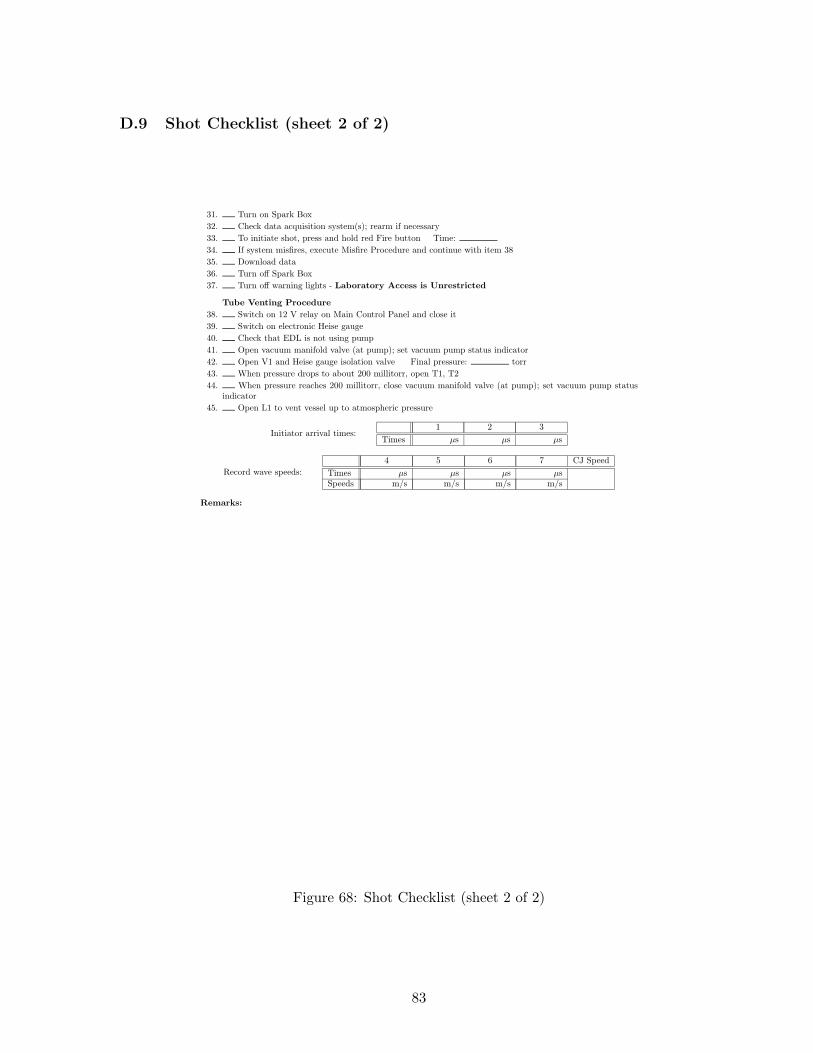
D.9 Shot Checklist (sheet 2 of 2)
31. Turn on Spark Box32. Check data acquisition system(s); rearm if necessary33. To initiate shot, press and hold red Fire button Time:34. If system misfires, execute Misfire Procedure and continue with item 3835. Download data36. Turn off Spark Box37. Turn off warning lights - Laboratory Access is Unrestricted
Tube Venting Procedure38. Switch on 12 V relay on Main Control Panel and close it39. Switch on electronic Heise gauge40. Check that EDL is not using pump41. Open vacuum manifold valve (at pump); set vacuum pump status indicator42. Open V1 and Heise gauge isolation valve Final pressure: torr43. When pressure drops to about 200 millitorr, open T1, T244. When pressure reaches 200 millitorr, close vacuum manifold valve (at pump); set vacuum pump status
indicator45. Open L1 to vent vessel up to atmospheric pressure
Initiator arrival times:1 2 3
Times µs µs µs
Record wave speeds:4 5 6 7 CJ Speed
Times µs µs µs µsSpeeds m/s m/s m/s m/s
Remarks:
Figure 68: Shot Checklist (sheet 2 of 2)
83
References
[1] P. Hung. Algorithms for Reaction Mechanism Reduction and Numerical Simulation of Det-onations Initiated by Projectiles. PhD thesis, California Institute of Technology, Pasadena,CA, June 2003.
[2] S. I. Jackson and J. E. Shepherd. Aiaa paper. Technical Report dunno yet, CaliforniaInstitute of Technology, 2002.
[3] M. J. Kaneshige. Gaseous Detonation Initiation and Stabilization by Hypervelocity Projec-tiles. PhD thesis, California Institute of Technology, Pasadena, CA, January 1999.
[4] J. E. Shigley and C. R. Mischke. Mechanical Engineering Design. McGraw Hill, Boston,MA, 2001.
84


