
Journal of Electrical and Electronic Engineering 2018; 6(2): 65-70
http://www.sciencepublishinggroup.com/j/jeee
doi: 10.11648/j.jeee.20180602.15
ISSN: 2329-1613 (Print); ISSN: 2329-1605 (Online)
Design and Implementation of Measurement System of Mechanical Parts with Multihole Based on Machine Vision
Chen Qiyu, Wang Yu, Wu Zhiheng, Tong Jigang, Mo Juexian
Guangdong Institute of Intelligent Manufacturing, Guangzhou, China
Email address:
To cite this article: Chen Qiyu, Wang Yu, Wu Zhiheng, Tong Jigang, Mo Juexian. Design and Implementation of Measurement System of Mechanical Parts with
Multihole Based on Machine Vision. Journal of Electrical and Electronic Engineering. Vol. 6, No. 2, 2018, pp. 65-70.
doi: 10.11648/j.jeee.20180602.15
Received: June 22, 2018; Accepted: August 4, 2018; Published: August 13, 2018
Abstract: The efficiency of the measurement of mechanical parts with multihole is needed to be improved in the
information era, while the size measurement of mechanical parts relying mainly on manual detection currently with very low
efficiency. To meet the repuiremant of equipment manufacturing automation, the efficiency of the measurement of mechanical
parts should match the speed of the line. As a new technology to solve the measurement problem of the objects with irregular
shape (such as multihole), machine vision provide a more effective way. To build a measurement system of mechanical parts
with multihole, there are many relevant aspects to be considered, such as the choices of hardware, software development,
algorithm design, ect. Image processing is one of the most important steps to build a successful visual system, which usually
consists of image preprocessing, image segmentation, feature extraction and defect classification. The design and
implementation of measurement system of mechanical parts with multihole based on machine vision will be discussed in this
paper. The experiment results show that the improved algorithm can effectively filter the noise of surface images, which make
the outline of the hole can be tested out easier. The system in this paper not only ensures the measurement precision of the pore
diameter of the workpiece, but also realizes the measurement of the pore diameter of the workpiece at the same time.
Keywords: Machine Vision, Mechanical Parts, Size Measurement
1. Introduction
With the rapid development of the equipment
manufacturing industries, such as aviation industry,
automobile industry, etc., the demand for relevant mechanical
parts of the equipments with complex structure is very great.
As a result, more and more mechanical parts with irregular
shape are manufactured, such as the mechanical parts with
multihole. Before assembling mechanical parts with holes,
the holes must be detected to ensure that the holes meet the
technical requirements of assembly. It is to say, the size
measurement of them have to be done first. At the same time,
the efficiency of the measurement of mechanical parts should
match the speed of the equipment manufacturing. For
example, stamping parts size measurement is the key link in
production. The traditional measuring means (such as
calipers, gauge, screw micrometer, etc.) is easy to operate,
but with big workload, low measuring efficiency and being
easily affected by man-made factors. It cannot be used for
online measurement, can not meet the requirement of the
modern mass, automated measurement [1].
China is a large manufacturing country, which produces a
large number of industrial products every day. Users and
manufacturers are increasingly demanding the quality of
products [2]. In recent years, in order to improve the
efficiency of the size measurement of mechanical parts, lots
of measurement technology and systems based on machine
vision technology are developed. Machine vision is the
technology and methods used to provide imaging-based
automatic inspection and analysis for applications such as
automatic inspection, process control, and robot guidance,
usually in industry. There are many advantages when doing
the size measurement base on machine vision, such as
non-contact, fast and efficient. The demand of intelligent
visual inspection systems aimed at ensuring the high quality
in production lines is increasing. Different measurement

Journal of Electrical and Electronic Engineering 2018; 6(2): 65-70 66
technology and systems based on machine vision technology
have been development around the world. Zhang Tian et al.
applying machine vision for bend space parameter
measurement, under the condition of specific measurements
to solve the large size complex elbow space parameter
measurement [3]. Wang Zhongfei et al. applying machine
vision to measure the thickness of microchip, reduced the
measurement system cost, and improved the measurement
speed [4]. Marco San Biagio et al. present a computer vision
system that, using only images, is able to address two main
problems: (i) model checking: automatically check whether a
component meets given specifications or rules, (ii) visual
inspection: defect inspection on irregular surfaces, in
particular, decolourization and scratches detection. [5]
But as to the size measurement of mechanical parts with
multihole, there are little literature review in this field. To
improve both the efficiency and accuracy of the measurement
of mechanical parts with multihole, this paper introduces a
measurement system based on machine vision. In this paper,
the overall framework of the system is proposed first, and
then the hardware selection is discussed. Image processing is
the most important part of the system development. Because
multihole is the key feature of the workpiece, so it is more
difficult for the measure system to complete the measure task.
Sometimes there are more than 3 holes within the workpiece,
even up to 10 holes with different size. Each hole has its own
characteristics. The holes must be identified simultaneously,
so the measuring system must accurately identify each hole
separately. In order to get accurate information, image
filtering, image segmentation, feature extraction should be
included. In order to solve the problem of image processing,
a special algorithm is designed. Finally, an experimental
summary is given.
2. Overall Framework of the System
The measurement system consists of two parts: the
hardware and the software, shown in figure 1.
Figure 1. Overall framework of the system.
The hardware of the measurement system mainly includes
the sensor system, optical lens, lighting, industrial camera,
computer and the auxiliary equipment. The software of the
system mainly includes computer software, control software,
and vision algorithm. The vision algorithm is the special
software that deal with the image of the mechanical parts,
usually including the preprocessing, measurement processing,
judgment and output module.
In fact, the overall framework of the measure system is a
normal framework. It is very similar to other machine vision
application systems. The suitable hardware selection is the
basic job, because the researchers have to build a real testing
environment. In fact, the biggest challenge is developing the
software.
When the workpiece triggers the image acquisition sensors,
the industrial camera will capture the surface images of
workpiece. The lighting helps the industrial camera to get
higher quality image. The image processing module doing
the edge contour feature extraction, identification and
measurement through a series of mathematical morphology
processing.
3. Discussion of the Choices of Hardware
How hardware is designed depends on the given
specification of the measurement. The actual vision system
usually selects different industrial cameras to collect images
according to color requirements and resolution. In this paper,
the mechanical part used for testing is made of steel.
Industrial camera requires high image quality, high
transmission rate and standard interface. In order to meet the
test requirements, the industrial camera with gmt200-h high
frame rate of 2 million pixels is used.
Different light sources have their distinguishable effects on
the quality of workpiece images acquisition. This system use
the LED (light emitting diode) backlight source while LED
has many excellent properties, such as long life,
energy-saving, better stability. By adjusting the position of
the light source and reducing the reflected light of the
workpiece, a good image acquisition quality can be obtained.
Industrial camera and LED backlight source are shown in
figure 2.
Computer
Industrial
CameraLighting
Optical LensSensor
System
Auxiliary
Equipment
Hardware
Computer
Software
Vision
Algorithm Control
Software
Measurement
Processing
Judgment
and OutputPreprocessing
Software
Measurement System

67 Chen Qiyu et al.: Design and Implementation of Measurement System of Mechanical
Parts with Multihole Based on Machine Vision
Figure 2. Industrial camera and LED backlight source.
The stability and reliability of the measurement system is
the premise of automation and intellectualization of the
assembly line of mechanical parts. This system uses different
sensors in this measurement system. The sensor can trigger
the image acquisition part at the beginning. Multi-sensor
fusion not only guarantees the accuracy of system detection,
but also makes the detection more intelligent. The parameters
of each sensor are listed below, shown in table 1.
Table 1. Sensors and their parameters.
Name of Sensor Model Main parameters
Photoelectric sensor GTD-2 Distance 30-150 mm
Displacement transducer KTC-1 ±0.01mm; 50~110mm
Wireless sensor JZH-0 25mA, 2000m
4. Image Processing
4.1. Image Acquisition
Image processing usually consists of image preprocessing,
image segmentation, feature extraction and defect
classification [6]. Image acquisition is the first step for the
vision system to obtain visual information.
The acquisition of high quality images can make the
images easy to process, and make the recognition and
positioning results more accurate as well. Usually both the
working environment and the equipment themselves affect
the quality of image acquisition. The image contains various
noises and uneven brightness [7]. In order to obtain higher
quality image, This system use industrial camera and LED
backlight source.
4.2. Image Feature Enhancement
Image enhancement can be used to make previously
unclear images clear, or to blur previously clear images to
meet the needs of some special analysis [8]. For the colour
image contains a large amount of information, using colour
image is more ideal to some extend. But at the same time it
raises higher request on the processing speed of image for the
processing system, because colour image texture feature is
more complex. The image texture of the workpicec in this
paper is relatively simple. Using the image gray level
information can not only complete the recognition of image
features, but also improve the speed of image processing.
Feature enhancement can improve the intensity of feature
signal in multihole feature images. The method of image
enhancement is to add some information or transform data to
the original image by means of certain means. It can
selectively highlight the features of interest in the image or
suppress some unnecessary features in the image, so that the
image and the visual response characteristics are matched.
The gray image feature enhancement is carried out in this
paper. The grayscale adjustment makes the feature
information of multihole feature images more obvious.
4.3. Image Filtering
Due to the digital image acquisition is much different from
that of the traditional picture, it is easy to be disturbed in
image acquisition and transmission links. As a result, the
digital image obtains irrelevant information while would
affect the image recognition. In order to improve the image
quality, the corresponding image preprocessing methods are
used to eliminate the noise interference. Image filtering is an
effective method to eliminate noise. Its theoretical basis is
image convolution. For example, the low pass filtering can
remove noise, while the high pass filtering can enhance high
frequency signals such as edge, so as to make the fuzzy
image more clear. The corresponding processing time of each
filtering method is different, and the processing effect is
different too. Each filter has its own advantages and
disadvantages, so it is necessary to select an appropriate filter
in the actual filtering process. In order to obtain the edge
information of workpiece, the edge information of workpiece
image needs to be saved while filtering.
High quality image is very important for the system to
analyse the characteristics of the workpiece in the actual
working condition. Usually the quality of original image is
not high enough to be processed directly. Image filtering is a
effective way to improve the quality of the image. Selecting
an appropriate filtering can not only eliminate the noise in the
image, but also avoid blurring the edge contour and line of
the image.
4.4. Image Threshold Segmentation
Common shape extraction techniques include threshold
segmentation and background subtraction. The background
Journal of Electrical and Electronic Engineering 2018; 6(2): 65-70 68
subtraction method assumes that the background is
accurately known. The foreground image can be obtained
by subtracting the current image from the background
image. When the camera collects images, it may be affected
by lighting, which will cause the background in the current
image to be significantly different from the previous one.
The threshold segmentation is applied to extract useful
shape information. Threshold segmentation is also called
binarization. Set a grayscale threshold for pixels in a
grayscale image to extract useful grayscale information.
The value of global threshold segmentation needs manual
setting and poor adaptability. Methods with adaptive
threshold include Otsu's method and adaptive global
threshold method. The basic idea of Otsu's method is to
divide the image gray histogram into two groups at a certain
threshold value. When the variance between the two groups
is maximum, the corresponding threshold is determined to
be the selected threshold value. In this section, image
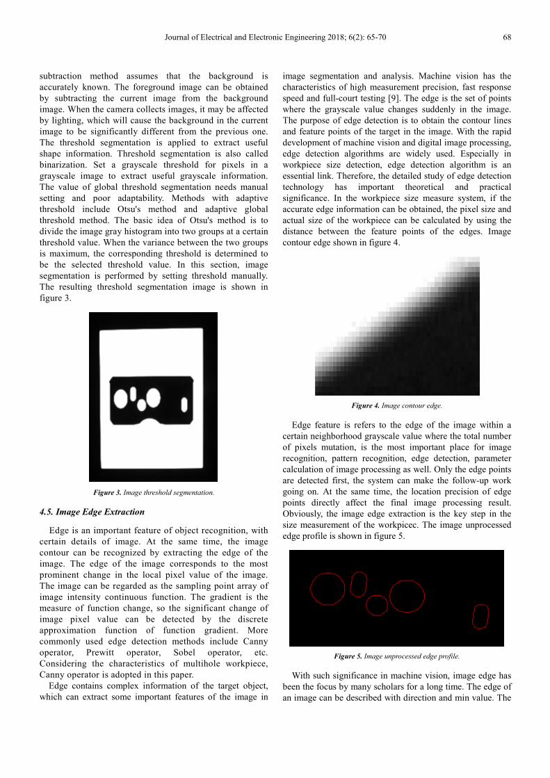
segmentation is performed by setting threshold manually.
The resulting threshold segmentation image is shown in
figure 3.
Figure 3. Image threshold segmentation.
4.5. Image Edge Extraction
Edge is an important feature of object recognition, with
certain details of image. At the same time, the image
contour can be recognized by extracting the edge of the
image. The edge of the image corresponds to the most
prominent change in the local pixel value of the image.
The image can be regarded as the sampling point array of
image intensity continuous function. The gradient is the
measure of function change, so the significant change of
image pixel value can be detected by the discrete
approximation function of function gradient. More
commonly used edge detection methods include Canny
operator, Prewitt operator, Sobel operator, etc.
Considering the characteristics of multihole workpiece,
Canny operator is adopted in this paper.
Edge contains complex information of the target object,
which can extract some important features of the image in
image segmentation and analysis. Machine vision has the
characteristics of high measurement precision, fast response
speed and full-court testing [9]. The edge is the set of points
where the grayscale value changes suddenly in the image.
The purpose of edge detection is to obtain the contour lines
and feature points of the target in the image. With the rapid
development of machine vision and digital image processing,
edge detection algorithms are widely used. Especially in
workpiece size detection, edge detection algorithm is an
essential link. Therefore, the detailed study of edge detection
technology has important theoretical and practical
significance. In the workpiece size measure system, if the
accurate edge information can be obtained, the pixel size and
actual size of the workpiece can be calculated by using the
distance between the feature points of the edges. Image
contour edge shown in figure 4.
Figure 4. Image contour edge.
Edge feature is refers to the edge of the image within a
certain neighborhood grayscale value where the total number
of pixels mutation, is the most important place for image
recognition, pattern recognition, edge detection, parameter
calculation of image processing as well. Only the edge points
are detected first, the system can make the follow-up work
going on. At the same time, the location precision of edge
points directly affect the final image processing result.
Obviously, the image edge extraction is the key step in the
size measurement of the workpicec. The image unprocessed
edge profile is shown in figure 5.
Figure 5. Image unprocessed edge profile.
With such significance in machine vision, image edge has
been the focus by many scholars for a long time. The edge of
an image can be described with direction and min value. The

69 Chen Qiyu et al.: Design and Implementation of Measurement System of Mechanical
Parts with Multihole Based on Machine Vision
complex structure of workpiece and the complicated
measurement process make it difficult to improve the
efficiency [10]. Generally speaking, along the direction of the
edge, the gray value changes little, while in the vertical
direction, the gray value changes greatly. It is very difficult to
describe the edge by pure mathematics. In order to express
the edge of the image more clearly, the edge of the image can
be described from the following four aspects:
(1) position of the edge: that is, the coordinate position of
the edge point, refers to the pixel coordinates of the point in
the image where the gray value changes;
(2) edge direction: the edge direction of a certain point in
the image refers to the direction that is tangent to the target
edge at that point;
(3) normal direction of the edge: perpendicular to the edge
direction;
(4) edge intensity change: refers to the local image
intensity change in the normal direction of the edge in a
neighborhood of the target edge point.
The image fitted measuring profile is shown in figure 6.
Figure 6. Image fitted measuring profile.
5. Experiment and Analysis
In this paper, the workpiece used for testing is one of
mechanical parts of automobile. Both the aperture and the
coordinate of the center of a circular hole of the workpiece
are needed to be measured.
Different parts of the workpiece have their own features.
In order to process images, it must understand regional
features, grayscale values, and contour features, etc.. As to
the measurement of mechanical part with multihole, both the
characteristics of the main edge contour features of holes,
and the variation of the edge contour have to be judged by
the direction of the gradient. At the same time, the direction
and boundary of the gradient shows different characteristics,
so the strength of the edge contour can be determined by
gradient mode change information.
Because the workpiece is manufactured by machines, its
surface is not so smooth. When the industrial camera
captures the surface image, the noise are also be gathered at
the same time. The noise not only influences the detection of
the edge contour, but also affects the measurement and
detection of the hole aperture in the later stage. To get the
higher quality image of the workpiece, developing the new
algorithm, instead of the general methods, is needed. The
images below show the difference. The middle image is the
the result using the general edge contour detection method,
while the right image is the other result using the improved
algorithm.
Figure 7. Experimental results of edge contour detection operator.
From the above experimental results, it can be found that
the improved algorithm can effectively filter the noise of
surface images. With the higher quality image, the outline of
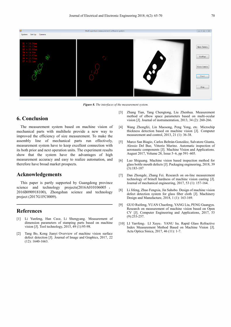
the hole can be tested out easier. The interfaces of the
measurement system are shown in figure 8.
Journal of Electrical and Electronic Engineering 2018; 6(2): 65-70 70
Figure 8. The interfaces of the measurement system.
6. Conclusion
The measurement system based on machine vision of
mechanical parts with multihole provide a new way to
improved the efficiency of size measurement. To make the
assembly line of mechanical parts run effectively,
measurement system have to keep excellent connection with
its both prior and next operation units. The experiment results
show that the system have the advantages of high
measurement accuracy and easy to realize automation, and
therefore have broad market prospects.
Acknowledgements
This paper is partly supported by Guangdong province
science and technology projects(2016A010106005 ,
2016B090918100), Zhongshan science and technology
project (2017G1FC0009).
References
[1] Li Yunfeng, Han Cece, Li Shengyang. Measurement of dimension parameters of stamping parts based on machine vision [J]. Tool technology, 2015, 49 (1):95-98.
[2] Tang Bo, Kong Jianyi Overview of machine vision surface defect detection [J]. Journal of Image and Graphics, 2017, 22 (12): 1640-1663.
[3] Zhang Tian, Tang Chengtong, Liu Zhenhua. Measurement method of elbow space parameters based on multi-ocular vision [J]. Journal of instrumentation, 2013, 34 (2): 260-266.
[4] Wang Zhongfei, Lin Maosong, Peng Yong, etc. Microchip thickness detection based on machine vision [J]. Computer measurement and control, 2013, 21 (1): 36-38.
[5] Marco San Biagio, Carlos Beltrán-González, Salvatore Giunta, Alessio Del Bue, Vittorio Murino. Automatic inspection of aeronautic components [J]. Machine Vision and Applications. August 2017, Volume 28, Issue 5–6, pp 591–605.
[6] Luo Shiguang. Machine vision based inspection method for glass bottle mouth defects [J]. Packaging engineering, 2018, 39 (3):183-187
[7] Dan Zhongde, Zhang Fei. Research on on-line measurement technology of brinell hardness of machine vision casting [J]. Journal of mechanical engineering, 2017, 53 (1): 157-164.
[8] Li Jifeng, Zhao Fengxia, Jin Sahobo. Design of machine vision defect detection system for glass fiber cloth [J]. Machinery Design and Manufacture, 2018, 1 (1): 163-169.
[9] GUO Ruifeng, YUAN Chaofeng, YANG Liu, PENG Guangyu. Research on measurement of machine vision based on Open CV [J]. Computer Engineering and Applications, 2017, 53 (9):253-257.
[10] LI Yarrfeng,LI Xuyu,YANU liu. Rapid Glass Refractive Index Measurement Method Based on Machine Vision [J]. Acta Optica Sinica, 2017, 46 (11): 1-7.


