
Design and Construction of the
Pearl City Peninsula to Ford
Island Waterline Crossing Project
Devin Nakayama, PE
Yogi Kwong Engineers, LLC
Richard (Bo) Botteicher, PE
Underground Solutions, Inc.
Presentation Agenda
Presentation will cover the main portion of the project,
which was the Horizontal Directional Drill (HDD) design
and installation.
• Project Background
• Design Overview
• Construction Highlights
• Lessons Learned
Project InformationOwner: NAVFAC Pacific
Civil: Fukunaga & Associates, Inc.
Structural: Shigemura, Lau, Sakanashi, Higuchi and Associates, Inc.
Electrical: MK Engineers, Ltd.
Environmental: Element Environmental, LLC
Geotechnical: Yogi Kwong Engineers, LLC
General Contractor: Watts - Healy Tibbits A JV
HDD Subcontractor: Southeast Directional Drilling
Fusion Subcontractor: Underground Solutions, Inc.
Contract Award: $10,024,207
Notice To Proceed: September 2013
Onsite Start: April 2014
HDD Completion: September 2014
Project Background
Replacement of approximately 3,800 linear feet of deteriorated
24-inch cast iron waterline with new 24-inch fusible
polyvinylchloride pipe (FPVCP) from Pearl City Peninsula to Ford
Island
• Operating Pressure: 65-75 psi (typical)
• Test Pressure: 150 psi
The 24-inch waterline will serve as a primary potable water artery
connecting the existing Pearl Harbor Complex with its primary
source (Waiawa Shaft).

Project Location
PEARL CITY
PENINSULA
FORD
ISLAND
WATERLINE
ALIGNMENT
WATERLINE
ALIGNMENT
• 3,800 LF of waterline to be replaced.
• 3,500 LF to be installed by HDD.
• 2,500 LF will be below Pearl Harbor channel.

Horizontal Alignment Selection
PEARL CITY
PENINSULAFORD
ISLAND
WATERLINE
ALIGNMENT
• Straight alignments in plan view typically preferred.
• Horizontal curve was necessary to avoid piers, and
make the connections to existing lines.
Reference: Google Earth

Alignment at Pearl City Peninsula
SECURED
COMPOUNDPROPERTY
LINE
PROPERTY
LINE
• Initial design was to replace roughly 3,330 LF of
existing waterline.
• 500 LF added to move closer to Secured Compound
and Forest City property line.
FOREST CITY
RESIDENTIAL AREA
Reference: Google Earth
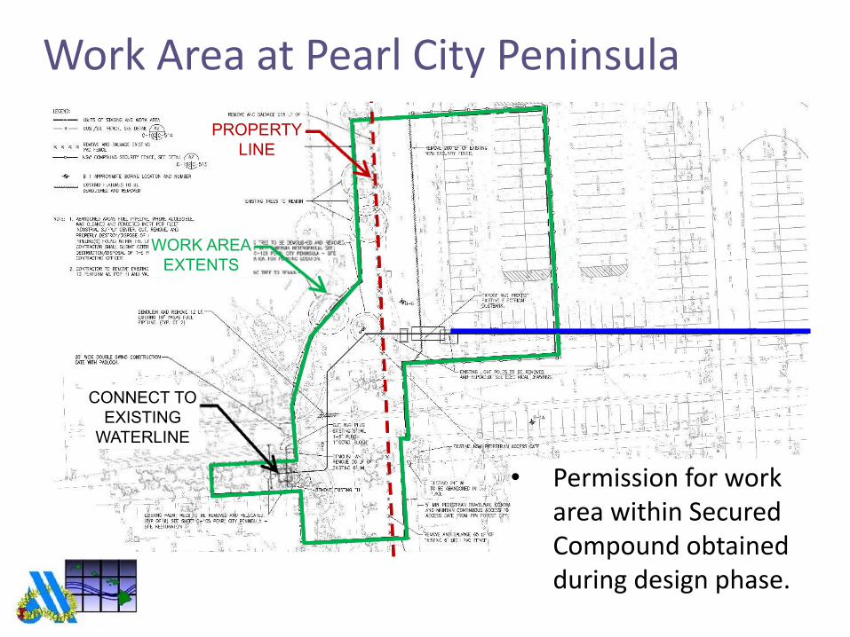
• Permission for work
area within Secured
Compound obtained
during design phase.
Work Area at Pearl City Peninsula
PROPERTY
LINE
PROPERTY
LINE
WORK AREA
EXTENTS
WORK AREA
EXTENTS
CONNECT TO
EXISTING
WATERLINE
CONNECT TO
EXISTING
WATERLINE

Alignment at Ford Island
UNDERGROUND
AMMO BUNKERS
UNDERGROUND
AMMO BUNKERS
PIPE STAGING AREAPIPE STAGING AREA
• 50’ clearance from underground ammo bunkers.
• Access to pipe staging area.
Reference: Google Earth
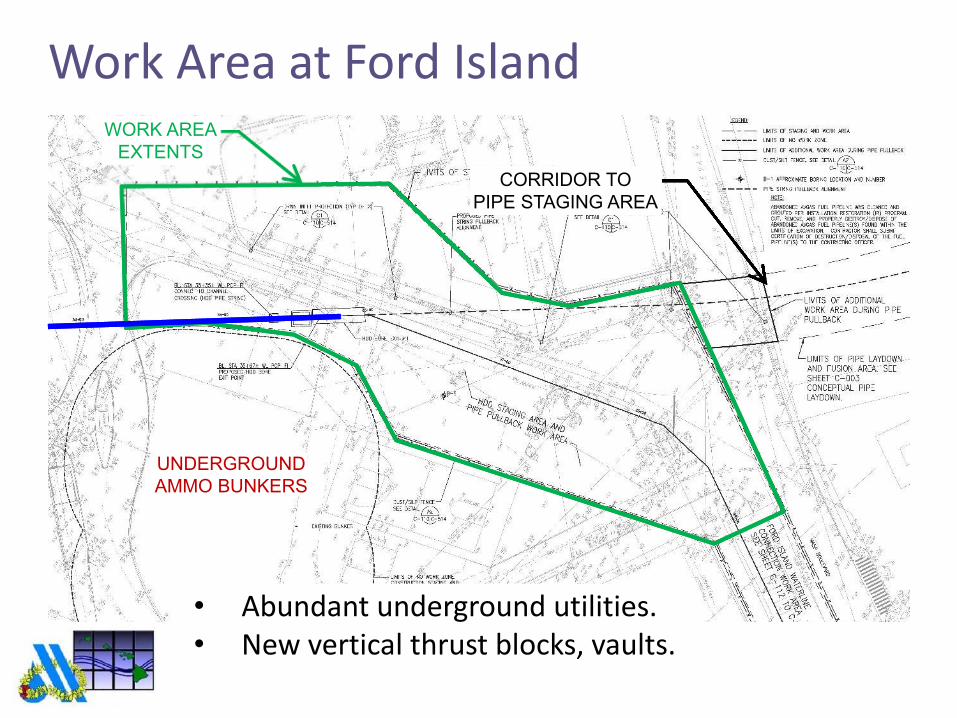
Work Area at Ford Island
• Abundant underground utilities.
• New vertical thrust blocks, vaults.
UNDERGROUND
AMMO BUNKERS
CORRIDOR TO
PIPE STAGING AREA
CORRIDOR TO
PIPE STAGING AREA
WORK AREA
EXTENTS
WORK AREA
EXTENTS

Ford Island Pipe Laydown Area
~3,500 FT OF
FUSIBLE PVC PIPE
~3,500 FT OF
FUSIBLE PVC PIPE
• 24-hour staging area for pipe laydown.
• Pullback in shorter segments while fusing in the
middle of pullback is feasible, but not preferred.

Geotechnical Exploration
• 5 on-land borings, 5 overwater borings.
• Deepest borings went to -140 feet MSL
• Additional borings on PCP side because of
potentially contaminated soils.
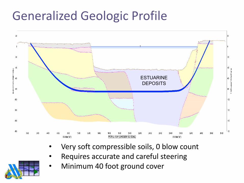
Generalized Geologic Profile
• Very soft compressible soils, 0 blow count
• Requires accurate and careful steering
• Minimum 40 foot ground cover
ESTUARINE
DEPOSITS

Generalized Geologic Profile
• Stiff to hard silts and clays
• Cobbles and boulders can typically be encountered
within alluvial deposits
ESTUARINE
DEPOSITSMARINE
DEPOSITSOLDER
ALLUVIUM
OLDER
ALLUVIUM
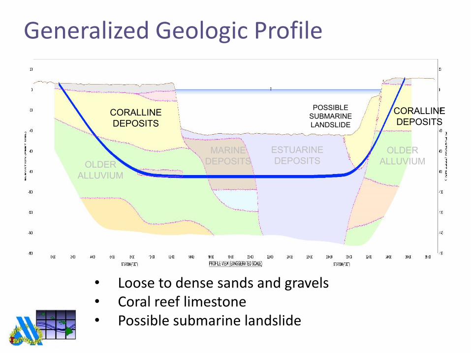
Generalized Geologic Profile
• Loose to dense sands and gravels
• Coral reef limestone
• Possible submarine landslide
ESTUARINE
DEPOSITSMARINE
DEPOSITS
CORALLINE
DEPOSITS
CORALLINE
DEPOSITS
POSSIBLE
SUBMARINE
LANDSLIDE
OLDER
ALLUVIUM
OLDER
ALLUVIUM
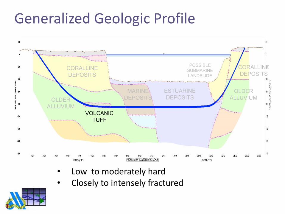
Generalized Geologic Profile
• Low to moderately hard
• Closely to intensely fractured
ESTUARINE
DEPOSITSMARINE
DEPOSITS
CORALLINE
DEPOSITS
CORALLINE
DEPOSITS
OLDER
ALLUVIUM
OLDER
ALLUVIUM
VOLCANIC
TUFF
POSSIBLE
SUBMARINE
LANDSLIDE
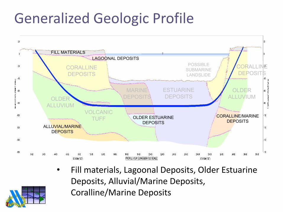
Generalized Geologic Profile
• Fill materials, Lagoonal Deposits, Older Estuarine
Deposits, Alluvial/Marine Deposits,
Coralline/Marine Deposits
ESTUARINE
DEPOSITSMARINE
DEPOSITS
CORALLINE
DEPOSITS
CORALLINE
DEPOSITS
OLDER
ALLUVIUM
OLDER
ALLUVIUM
VOLCANIC
TUFF
POSSIBLE
SUBMARINE
LANDSLIDE
FILL MATERIALS
LAGOONAL DEPOSITS
OLDER ESTUARINE
DEPOSITSALLUVIAL/MARINE
DEPOSITS
CORALLINE/MARINE
DEPOSITS
Environmental Issues
• Potentially contaminated soils were encountered during
geotechnical drilling at Pearl City Peninsula (PCP).
• Specifications require a larger diameter protective steel casing
(conductor barrel) to be installed at the PCP end of the HDD
alignment.
• Isolate possible contaminated soils and groundwater from the
HDD slurry returns.
• Conductor barrel to extend at least 15 feet below Mean Sea
Level.

Inadvertent Mud Returns
• Potential for inadvertent returns is highest where ground
cover is less than 15 feet, such as near on-land entry / exit pits.
• Measures to minimize the potential for inadvertent returns
include lowering the drill path depth to approximately 40 feet
below the mudline of the deepest part of the channel.
• Contractor required to submit detailed work plan to minimize
potential inadvertent mud return and contingency plans in the
event of inadvertent returns.

Contractor Qualifications and Submittals
• Project specifications required experienced and qualified HDD
contractor and personnel, who have performed similar work
under waterways in similar ground conditions and ground
cover.
• Required preconstruction submittals include HDD Work Plan
and contingency measures.
• Contractor required to retain QC specialist full-time onsite
during HDD operations.

48-inch Isolation Casing
• 170 ft installed from the PCP side.
• Tip of casing extended below groundwater.
• Isolate potential contaminated soils.
ISOLATION CASINGISOLATION CASING
DRILL RODSDRILL RODS
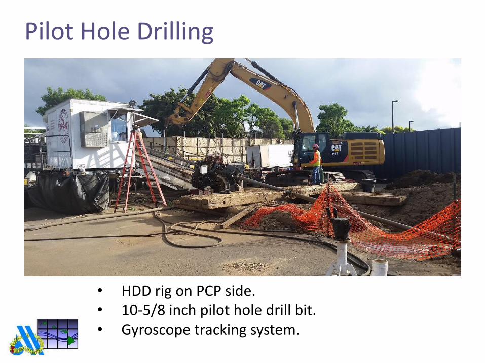
Pilot Hole Drilling
• HDD rig on PCP side.
• 10-5/8 inch pilot hole drill bit.
• Gyroscope tracking system.

Pilot Hole Breakthrough
TARGETED
EXIT POINT
TARGETED
EXIT POINT
PILOT HOLE
DRILL BIT
PILOT HOLE
DRILL BIT
• Actual exit point was inside excavated exit pit, 3
feet below target.

Reaming
• Initial plan by Contractor was to ream with 24-inch,
then 38-inch reamer.
• Contractor elected to ream entire length in one
pass with 38-inch reamer.

Reaming
DRILL RODSDRILL RODS
• Track excavator was used to pull the reamer
through the hole, from the PCP side to Ford Island.
• Rotation was provided by HDD rig on PCP side.

Mud / Swab Pass
• Performed prior to pullback with 36-inch ball
reamer.
• Ball reamer pulled from Ford Island to PCP side.

Pipe Fusion and Staging
• 24-inch AWWA C905 PVC Pressure Pipe DR 18, PC
235 psi
• Thermally Butt-Fused = Fusible PVC® pipe
• McElroy T-900 fusion equipment – Underground
Soltuions, Inc. Fusion Technician.
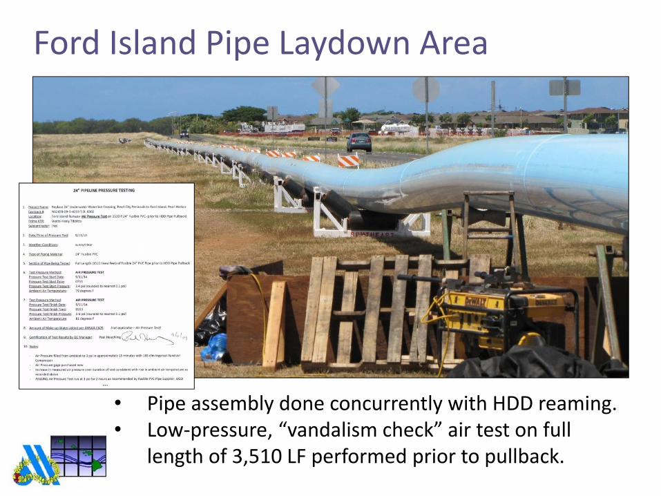
Ford Island Pipe Laydown Area
3,500 FT OF
FUSIBLE PVC PIPE
3,500 FT OF
FUSIBLE PVC PIPE
• Pipe assembly done concurrently with HDD reaming.
• Low-pressure, “vandalism check” air test on full
length of 3,510 LF performed prior to pullback.

Pipe Assembly Schematic
Pipe Fusion
Assembly
Area
Pipe Fusion
Assembly
Area
Assembled Pipe String
Staged, 3,510 LF
Assembled Pipe String
Staged, 3,510 LF
Reference: Google Earth
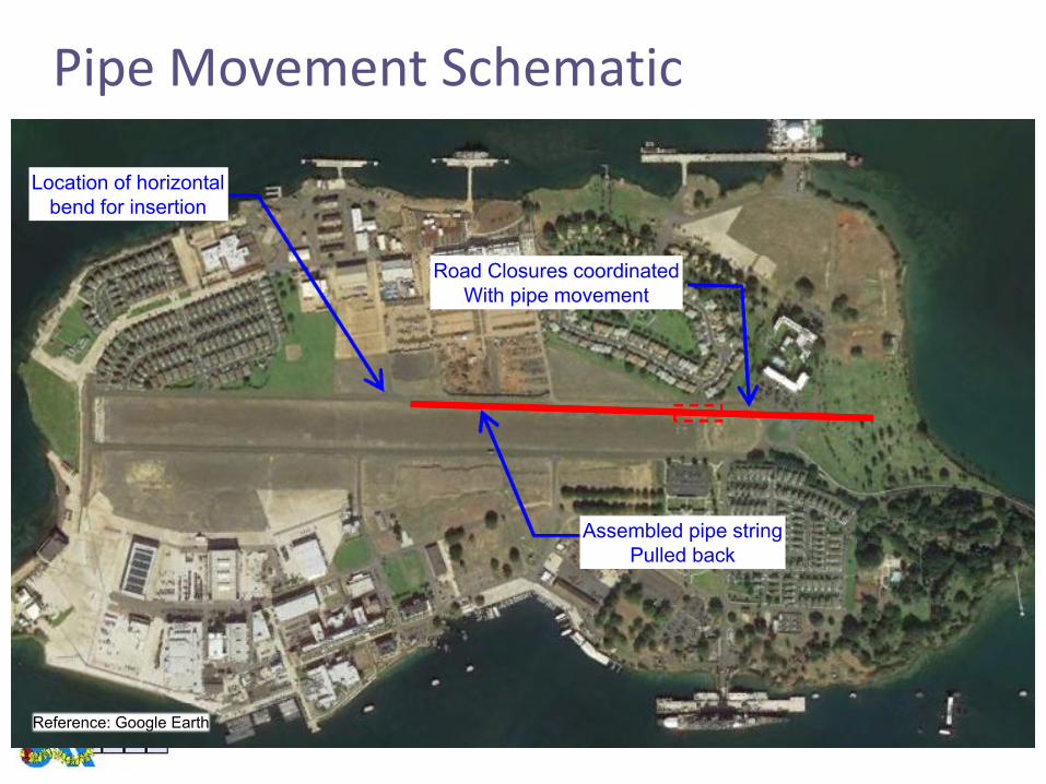
Pipe Movement Schematic
Assembled pipe string
Pulled back
Assembled pipe string
Pulled back
Location of horizontal
bend for insertion
Location of horizontal
bend for insertion
Road Closures coordinated
With pipe movement
Road Closures coordinated
With pipe movement
Reference: Google Earth

Pipe Movement Schematic
Final position for
insertion
Final position for
insertion
Location of
insertion
Location of
insertion
Road Closures coordinated
With pipe movement
Road Closures coordinated
With pipe movement
Reference: Google Earth
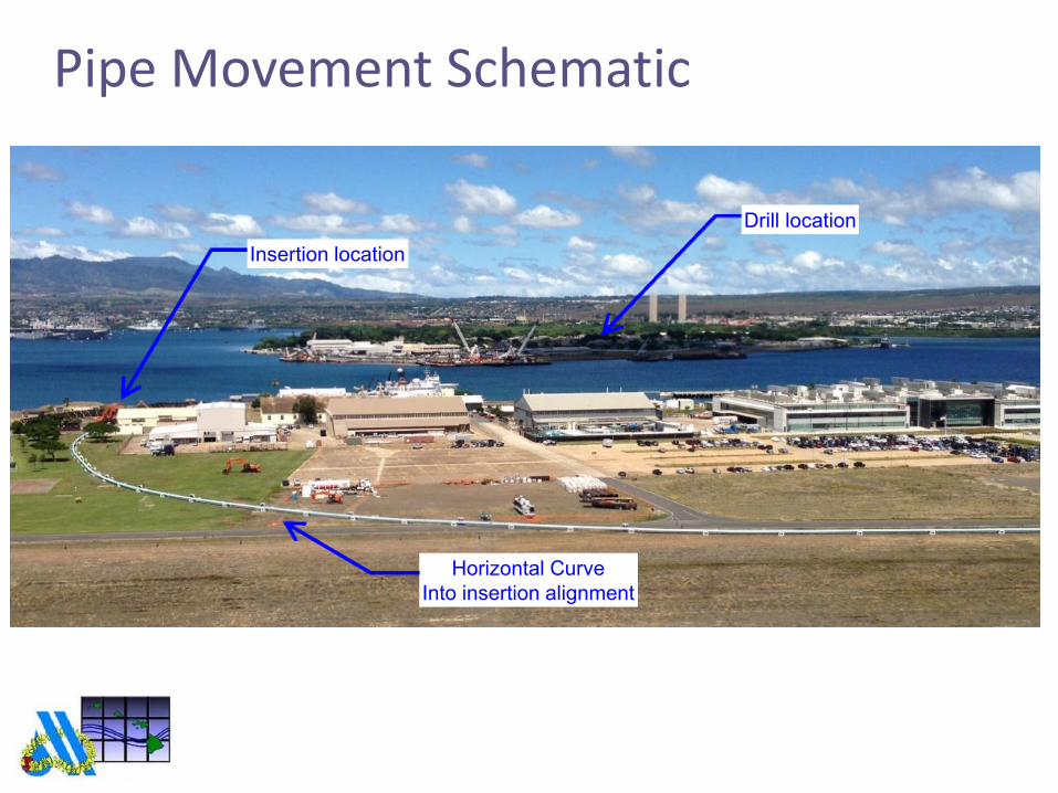
Pipe Movement Schematic
Horizontal Curve
Into insertion alignment
Horizontal Curve
Into insertion alignment
Insertion locationInsertion location
Drill locationDrill location

Pipe Alignment Specifics
• At-grade alignment surveyed in from
plan.
• Alignment used to meet bend radius
requirements and avoid obstacles.
TreesTrees
Baseball field
backstop
Baseball field
backstop

Pipe Roller Set Ups
• Fully supported
on rollers
entire time
• Lateral support
on horizontal
curve
• Fabricated
‘skids’ during
staging
• Less desirable
rollers used for
initial
movement
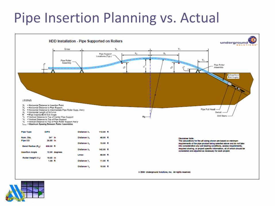
Pipe Insertion Planning vs. Actual

Pipe Insertion Planning vs. Actual
• Slight horizontal deflection
accommodated
• Three pick-points used to elevate
the pipe and curve to the correct
insertion angle

Internal Ballasting
Clean water pumped into pipe as it is
inserted to reduce buoyant drag,
reduce pull forces required

Pipe Pullback Forces
Estimated maximum
pullback force:
Actual maximum
pullback force observed:
Force required to pull
drill rig carriage:
Safe pulling force
for 24” DN :
140,000 to 150,000 lbs
164,000 lbs
~17,000 lbs
307,100 lbs

Challenges and Lessons Learned:
• Never underestimate the value of good
teamwork
– Ideas and problem solving
– Experts in their respective fields
• Field test processes as much as practical!
– Ballast water flow check
• When the going gets tough, the tough get
creative
– Use of ‘fashioned’ roller cradle
– Use of fabricated pipe supports
– Roller supports for curves
– Adjustment of roller supports during staging
movement
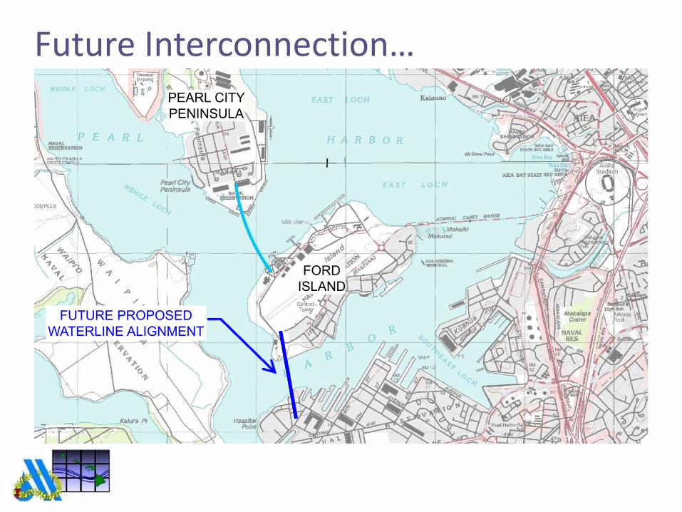
Future Interconnection…
PEARL CITY
PENINSULA
FORD
ISLAND
FUTURE PROPOSED
WATERLINE ALIGNMENT
FUTURE PROPOSED
WATERLINE ALIGNMENT
Design and Construction of the
Pearl City Peninsula to Ford
Island Waterline Crossing Project
Devin Nakayama, PE
Yogi Kwong Engineers, LLC
Richard (Bo) Botteicher, PE
Underground Solutions, Inc.


