
1
150 - 3,000 scfm | AEHD Series
Front Page
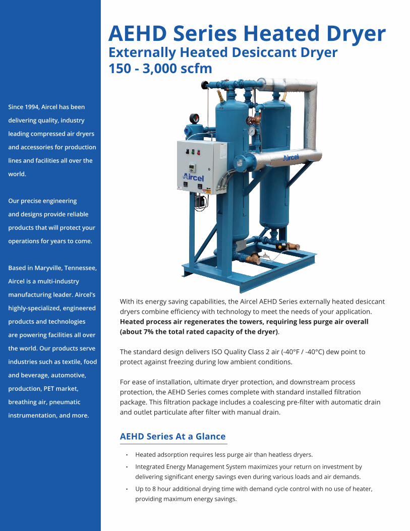
Desiccant Air DryersAEHD SeriesExternally Heated Desiccant Air Dryer150 - 3,000 scfm
2
Since 1994, Aircel has been
delivering quality, industry
leading compressed air dryers
and accessories for production
lines and facilities all over the
world.
Our precise engineering
and designs provide reliable
products that will protect your
operations for years to come.
Based in Maryville, Tennessee,
Aircel is a multi-industry
manufacturing leader. Aircel’s
highly-specialized, engineered
products and technologies
are powering facilities all over
the world. Our products serve
industries such as textile, food
and beverage, automotive,
production, PET market,
breathing air, pneumatic
instrumentation, and more.
With its energy saving capabilities, the Aircel AEHD Series externally heated desiccant dryers combine efficiency with technology to meet the needs of your application. Heated process air regenerates the towers, requiring less purge air overall (about 7% the total rated capacity of the dryer).
The standard design delivers ISO Quality Class 2 air (-40°F / -40°C) dew point to protect against freezing during low ambient conditions.
For ease of installation, ultimate dryer protection, and downstream process protection, the AEHD Series comes complete with standard installed filtration package. This filtration package includes a coalescing pre-filter with automatic drain and outlet particulate after filter with manual drain.
AEHD Series Heated DryerExternally Heated Desiccant Dryer150 - 3,000 scfm
• Heated adsorption requires less purge air than heatless dryers.
• Integrated Energy Management System maximizes your return on investment by
delivering significant energy savings even during various loads and air demands.
• Up to 8 hour additional drying time with demand cycle control with no use of heater,
providing maximum energy savings.
AEHD Series At a Glance
Energy Management Standard

3
The AEHD Series dryers come standard with the Aircel Energy Management System - a technology that utilizes desiccant bed humidity sensing to maintain dew point and provide energy savings.
This Energy Management System or demand cycle control system reduces purge air and optimizes dryer performance by monitoring the moisture at the mid portion of the tower desiccant bed. This allows for quick response to moisture changes while maintaining the low outlet dew point.
The control system automatically adjusts the regeneration cycle, maintaining outlet dew
point and extending the drying cycle during periods of lower loading. Switching is less frequent, reducing dryer maintenance and fully utilizing desiccant capacity. This addition improves reliability and performance while sustaining the low outlet dew point. The end result is an overall purge reduction and significant energy savings.
• Mid-bed humidity sensors provide constant desiccant monitoring, ensuring stable dew point performance.
• Compressed purge air consumption, heater, and blower usage are reduced, optimizing energy performance.
• Up to 8 hours additional drying with demand cycle control.
Energy Management Standard
4
AEHD Series | 150 - 3,000 scfm
• Various configurations of pre-piped filters and bypass valve package
• Failure to switch alarm using pressure transducers (monitors for correct vessel pressure during dryer operation, energizes alarm if incorrect)
• Outlet dew point monitoring
• Optional communications: Profibus-DP, AS-I, CANpen, DeviceNet, and Ethernet
• NEMA 7 explosion-proof electrical classification (class 1, division 2, group C and D)
Additional Standard Features Optional Equipment
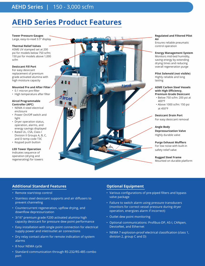
AEHD Series Product FeaturesTower Pressure GaugesLarge, easy-to-read 3.5” display
Thermal Relief ValvesASME UV stamped set at 200 psi for models below 750 scfm; 150 psi for models above 1,000 scfm
Desiccant Fill PortFor easy desiccant replacement of premium grade activated alumina with high moisture capacity
Mounted Pre and After Filter• 0.1 micron pre-filter• High temperature after filter
Aircel Programmable Controller (APC)• NEMA 4 steel electrical
enclosure• Power On/Off switch and
light• Dryer operation status,
operation, alarms, and energy savings displayed
• Rated UL, CSA, Class I Division II Groups A, B, C, and D temp code T3C
• Keypad push button
LED Tower OperationIndicates sequence of operation (drying and regenerating) for towers
Regulated and Filtered Pilot AirEnsures reliable pneumatic control operation
Energy Management SystemMonitors mid-bed humidity, saving energy by extending drying times and reducing overall regeneration purge
Pilot Solenoid (not visible)Highly reliable and long lasting
ASME Carbon Steel Vessels with High Efficiency, Premium Grade Desiccant• Below 750 scfm: 200 psi at
400°F• Above 1000 scfm: 150 psi
at 450°F
Desiccant Drain PortFor easy desiccant removal
Angle Body Depressurization ValveHighly durable valve
Purge Exhaust MufflersFor low noise with built-in safety relief valve
Rugged Steel FrameMounted on durable platform
• Remote start/stop control
• Stainless steel desiccant supports and air diffusers to prevent channeling
• Countercurrent regeneration, upflow drying, and downflow depressurization
• 3/16” premium grade F200 activated alumina high capacity desiccant for pressure dew point performance
• Easy installation with single point connection for electrical supply power and inlet/outlet air connections
• Dry relay contact alarm for remote indication of system alarms
• 8 hour NEMA cycle
• Standard communication through RS-232/RS-485 combo port

5
150 - 3,000 scfm | AEHD Series
AEHD Series - How It Works
A
D
C
B
B
C
F
Pre
-Fil
ter
Tower 1 Tower 2
Heater
Aft
er
Fil
ter
• Compressed air flows through the pre-filter to remove oil and then enters the on-line Tower 1 through valve (A).
• Air moves upward, where the desiccant removes moisture from the air stream. The majority of clean, dry compressed air exits valve (B) and cycles through the after filter to then flow downstream.
• During the drying process, a small amount of the clean air exiting valve (B) travels to Tower 2 (shown in regeneration mode) to assist in the regeneration process.
• To regenerate Tower 2, valve (C) opens and the tower is depressurized to near atmospheric pressure. The air flowing from valve (B) moves down the tower, removing moisture from the desiccant bed. Once it travels to the bottom of Tower 2, it exits the tower through valve (C) and the exhaust muffler to ambient.
• Once Tower 2 is fully regenerated, valve (C) will close, repressurizing Tower 2 to line pressure with the slight airflow coming through valve (B).
• Next, valve (D) will open to depressurize Tower 1 and valve (A) will switch (not pictured), directing wet incoming air to Tower 2 for drying while Tower 1 is regenerating the desiccant bed.
• This process will repeats continuously every 4 hours unless the Energy Management System is extending drying time period during low load conditions to a maximum of 12 hours each cycle. The Energy Management System continually monitors the mid-bed humidity level in the drying tower to save energy by extending the drying cycle (up to 12 hours).
DrainValve
Air or WaterCooled
Condenser
AirCompressor
DrainValve
Dry Airto Plant
DrainValve
After Filter
Pre-Filter
Separator
DrainValve
Recommended Installation

6
AEHD Series | 150 - 3,000 scfm
Aftermarket Parts & ServiceAircel’s aftermarket and service teams will assist you with the information necessary to ensure your air is pure for years
to come. From the vital data about your dryer’s capabilities and details on how to install parts into your dryer, as well as
pricing and ordering information, you have the convenience of ordering the products you need when you need them.
For manuals, drawings, spare parts including service kits, and technical support for your dryer, please contact your Aircel
representative.

7
Inlet Temperature (°F) 70 80 90 100 105 110 120
Correction Factor 1.2 1.15 1.1 1 0.9 0.8 0.6
Correction Factors for Differing Inlet Air Temperature (C1)
To Size the Dryer Capacity for Actual ConditionsAdjusted Capacity = scfm x (C1 x C2)Example: Dryer Model: AEHD-500 Standard Capacity: 500 scfm Actual Operating Conditions: 80°F inlet: C1 = 1.15 90 psig system pressure: C2 = 0.91
Adjusted Capacity: 500 scfm x (1.15 x 0.91) = 523 scfm
Specifications | AEHD Series
Aftermarket Parts & ServiceDimensions (in.)
To Size the Dryer Capacity for Actual Conditions
Model Number Capacity Voltage Connection
Heater kW (full load) FLA
Weight (lbs) Height Width Depth
AEHD-150 150
460-3-60
1” NPT 2.5 3.7 1,000 77 58 36
AEHD-250 250 1-1/2” NPT 3.75 5.2 1,500 87 58 44
AEHD-350 350 2” NPT 6 8.1 2,000 87 62 53
AEHD-500 500 2” NPT 7 9.3 2,300 87 66 53
AEHD-750 750 2” NPT 11 14.3 2,700 89 70 53
AEHD-1000 1,000 3” FLG 15 19.4 4,100 92 80 68
AEHD-1250 1,250 3” FLG 18 23.1 4,900 97 85 68
AEHD-1400 1,400 3” FLG 22 28.2 5,200 97 85 68
AEHD-1600 1,600 4” FLG 27 34.4 7,200 99 85 73
AEHD-2000 2,000 4” FLG 32.5 41.3 7,800 109 94 91
AEHD-2500 2,500 4” FLG 37 47 9,500 109 94 94
AEHD-3000 3,000 6” FLG 45 57 11,500 119 113 102
Capacity rated in accordance with CAGI ADF 200 @ 100 psig, 100°F inlet, 100°F ambient and a PDP of -40°F
Operating pressure: 60 to 150 psig | Ambient air temperature: 38°F to 125°F | Inlet air temperature: 40°F to 1!0°F
For larger capacities and custom dryer options, please contact an Aircel factory representative
Capacity Correction Factors
System Pressure (psig) 60 70 80 90 100 110 120 130 140 150
Correction Factor 0.65 0.73 0.82 0.91 1 1.09 1.18 1.27 1.35 1.44
Correction Factors for Differing System Air Pressure (C2)
Adjusted Capacity = scfm / (C1 x C2) Example: Given Flow: 500 scfm Actual Operating Conditions: 80°F inlet: C1 = 1.15 130 psig system pressure: C2 = 1.27
Adjusted Capacity: 500 scfm / (1.15 x 1.27) = 342 scfmSelected Dryer Model: AEHD-350
To Size the Dryer Model for Actual Conditions

8
AEHD Series | 150 - 3,000 scfm
323 Crisp Circle · Maryville, TN 37801 | office: 865-681-7066 | [email protected]
Please visit us at airceldryers.com
Aircel, LLC. reserves the right to update or change specifications at any time without prior notice.


