
DEPARTMENT OFENVIRONMENTAL CONSERVATION
ALASKA I/M PROGRAM MANUAL
Including Inspection and Repair Proceduresfor Certified Mechanics and Certified Stations
February 21, 2002

i.
This manual is to be used with 18 AAC 52, Emissions Inspectionand Maintenance Requirements for Motor Vehicles. Thismanual includes simplified informative summaries of portions of18 AAC 52. If clarification is needed, please review theapplicable provisions of 18 AAC 52, which are legally controlling.

ii.
TABLE OF CONTENTS
Part I: Alaska2000 Emissions Inspection System (EIS)
Section 1 - General Specifications ...................................................... page 21. Background Information ......................................................................... page 22. List of Abbreviations................................................................................ page 33. General Specifications.............................................................................. page 4
a. Microcomputer Compatibility................................................................ page 4b. User Interface ........................................................................................ page 4c. Year 2000 Compliance .......................................................................... page 4d. Communications.................................................................................... page 4e. Operating System.................................................................................. page 4f. Data Storage.......................................................................................... page 4g. Test Analyzers....................................................................................... page 4h. Design/Construction.............................................................................. page 5i. Useful Life ............................................................................................ page 5j. Applicable Codes .................................................................................. page 5k. Data Storage.......................................................................................... page 5l. Technical and System Documentation ................................................... page 7m. Availability of Circuitry......................................................................... page 7n. Telephone Requirements ....................................................................... page 8o. Printer ................................................................................................... page 8p. Bar Code Readers.................................................................................. page 8q. Clock/Calendar...................................................................................... page 8r. Test Record Storage .............................................................................. page 8s. Data and File Transfer ........................................................................... page 8t. Software Versions/Updates/ Modifications ............................................ page 9u. Tamper Resistance.................................................................................page 10v. Authorized ADEC Representative Access to Test Records ....................page 11w. State Menu Access ................................................................................page 11x. EIS Startup............................................................................................page 11y. Lockout Notification..............................................................................page 12z. High Throughput Testing Capability......................................................page 12aa. Preliminary I/M Test Data Entry............................................................page 12bb. Pollutant Measurement ..........................................................................page 12cc. Engine RPM Measurement ....................................................................page 13dd. Exhaust Dilution Correction ..................................................................page 13ee. Capability to Access OBDII Readiness and Fault Codes........................page 13ff. Manual Testing Mode……………………………………………………page 13gg. Training Test .........................................................................................page 13

iii.
hh. Vehicle Repair and Diagnostics Application..........................................page 14ii. Diagnostic Functions .............................................................................page 14
Section 2 - Software Functions .......................................................... page 151. General ......................................................................................................page 152. I/M Mechanic Access Procedure...............................................................page 153. Applicable Model Years ............................................................................page 164. Vehicle Body Type.....................................................................................page 165. Vehicle Make Entries ................................................................................page 176. Vehicle Model Entries ...............................................................................page 177. Engine RPM Detection..............................................................................page 178. Dual Exhaust .............................................................................................page 189. Emission Standards...................................................................................page 1810. Dilution Correction ...................................................................................page 1911. Blind Test...................................................................................................page 1912. Data Storage and Recall Capability..........................................................page 1913. Warranty Message on VIR .......................................................................page 1914. Decision Criteria........................................................................................page 1915. VID Communications Processes ...............................................................page 2016. Receive System Date/Time Update ...........................................................page 2017. Lockout Processing....................................................................................page 2018. Receive ADEC or
Local I/M Program Messages ..................................................................page 2119. Updates to Vehicle Reference Table (VRT) and
Emission Standards Category (ESC) Tables ............................................page 2120. Receive Updates of Analyzer Lockout Status...........................................page 2221. Receive I/M Mechanic Data .....................................................................page 2222. Receive System Data .................................................................................page 2323. Gas Calibration and Leak Check Frequency ...........................................page 2324. Hard Disk Warning Message ....................................................................page 2325. Print Screen Capability.............................................................................page 2326. Aborted Test Recording ............................................................................page 24
Section 3 - Display and Program Requirements ................................ page 251. General Description....................................................................................page 252. Menu Overview ..........................................................................................page 263. Vehicle Emissions Inspection .....................................................................page 283-1. Official I/M Test ......................................................................................page 28
I. General Requirements............................................................................page 28 a. VID Connection..................................................................................page 28 b. EIS Gas Calibration............................................................................page 28 c. Check for Lockouts…………………………………………………….page 28
d. Abort Procedure………………………………………………………..page 29 II. TEST INITIATION/ VEHICLE DATA ENTRY ..................................page 30 a. Access Code Entry..............................................................................page 30

iv.
b. Test Type............................................................................................page 31 c. Data Entry for Vehicle Identification ..................................................page 33 d. Data Entry if no RRN .........................................................................page 34 e. VID Communications .........................................................................page 35 f. Manual Entry if No VID Connection...................................................page 37 g. Odometer............................................................................................page 47 h. Dual Exhaust ......................................................................................page 47 i. Vehicle Data Entry Confirmation Screen ............................................page 48 j. VRT Lookup ......................................................................................page 49 III. VISUAL INSPECTION OF EMISSION CONTROL SYSTEMS...........page 50
a. Display Prompt...................................................................................page 50b. Programming Criteria .........................................................................page 51
IV. FUNCTIONAL CHECKS OF EMISSION CONTROL SYSTEMS .......page 54 a. Display Prompt ...................................................................................page 54
b. Programming Criteria .........................................................................page 54 c. Confirm Data Entry for Visual and Functional Inspection ...................page 56 d. Vehicle – EIS Hookup ........................................................................page 57 e. OBDII Test Procedure ........................................................................page 59 V. EMISSIONS INSPECTION (Tailpipe)…………………………………..page 77 a. General Requirements........................................................................page 77 b. Sample System Readiness..................................................................page 78 c. Dilution Correction Factor (DCF) ......................................................page 79 d. Two-speed Idle Tailpipe Test Procedure............................................page 80 VI. RECORDING TEST RESULT DATA...................................................page 93 VII. REPAIR DATA ENTRY PROCEDURE ...............................................page 93 a. Repair Categories...............................................................................page 93 b. Parts and Labor Cost (only for test type “A”).....................................page 94 VIII. FINAL RESULTS AND PRINTING OF VIR ......................................page 95 a. Overall Pass/Fail Determination.........................................................page 95 b. Previous Sticker Entry .......................................................................page 95 c. Sticker Number Verification ..............................................................page 96 d. Print Certificate/Insert .......................................................................page 97 e. Sticker Placement ..............................................................................page 97 f. Local Data Recording.........................................................................page 98
g. VID Data Transfer..............................................................................page 98 h. Print VIR...........................................................................................page 98
3-2. Analyzer Maintenance Menu .................................................................page 99 a. Gas Calibration and Leak Check ........................................................page 99 b. Leak Check Only.............................................................................. page 100 c. Gas Calibration Only ........................................................................ page 100 d. Status Screen .................................................................................... page 101 3-3. Manual Test Mode .................................................................................. page 102 3-4. VIR Reprint plus Test Record Search.................................................... page 102 4. Operator Training ................................................................................... page 103 5. Station Menu ........................................................................................... page 104 6. State Menu............................................................................................... .page 113

v.
7. Manufacturer’s Service Menu ................................................................. page 118
Section 4 - Test Record Specifications ..................................................page 1191. General Specifications............................................................................... page 119
Table: CAL, CALHST ............................................................................... page 120Table: DTC ................................................................................................ page 121Table: EIS, EISHST ................................................................................... page 121Table: ESC................................................................................................. page 130Table: LOADSTICKER ............................................................................. page 130Table: LOCKOUT...................................................................................... page 130Table: MAIL MESSAGES......................................................................... page 131Table: OBD EXEMPTIONS ...................................................................... page 131Table: REGION ......................................................................................... page 132Table: STATION ....................................................................................... page 133Table: STICKER........................................................................................ page 133Table: TECH.............................................................................................. page 134Table: VRT ................................................................................................ page 134
Section 5 - Vehicle Inspection Report and Printer FunctionSpecifications ................................................................................................ page 135
1. Vehicle Inspection Report ......................................................................... page 1352. Printer Functions and Specifications........................................................ page 1363. Bar Codes .................................................................................................. page 136
Section 6 - Technical Specifications for the Analyzer System ..............page 1371. Overview .................................................................................................... page 1372. Acceptance and Certification.................................................................... page 1373. Minimum Required Configuration........................................................... page 1384. Calibration Gases ...................................................................................... page 1415. Documentation to be Provided only to ADEC ......................................... page 142
Section 7 - Documentation, Logistics, and Warranty Requirements ....page 1441. General ...................................................................................................... page 1442. Instruction Manual ................................................................................... page 1443. EIS Warranty ............................................................................................ page 1454. Disclosure Statement ................................................................................. page 1475. Replacement Parts..................................................................................... page 1486. Workmanship ............................................................................................ page 1487. Parts Removed........................................................................................... page 1488. Noncompliance with any Portion of the EIS Specifications..................... page 148

vi.
Part II: Mechanic Training Course Requirements
a. Basic Material........................................................................................... page 151b. Required Supplements ............................................................................. page 151c. Instructor Qualifications.......................................................................... page 151d. Material to be Covered............................................................................. page 151e. Instruction Requirements ........................................................................ page 154f. Testing Requirements............................................................................... page 155g. Facility and Equipment Requirements.................................................... page 155
Part III: General Information for Certified Mechanics
a. How to apply for Certification .................................................................. page 158b. Certification Testing.................................................................................. page 159c. Training Courses ....................................................................................... page 159d. Renewal of Certification ........................................................................... page 159e. Study Materials ......................................................................................... page 159f. Continuing I/M Education ........................................................................ page 159g. Tech Line ................................................................................................... page 159
Part IV: Inspection and Repair Procedures and Standards
∗ Requirements Before Beginning an I/M Test................................................. page 163∗ General Procedures…….. ............................................................................... page 164∗ Preliminary Inspection ................................................................................. page 165∗ Identifying Grey Market Vehicles ................................................................ page 165∗ Cost Quotation….…........................................................................................ page 166∗ Used Automobile Dealers................................................................................ page 166∗ The Test…………………………………………………………………………page 166
a. Beginning Official I/M Test ...................................................................... page 166b. Identify the Emission Control System Applications ................................ page 172c. Perform Visual Inspection ........................................................................ page 173d. Perform Functional Inspection ................................................................. page 180e. Confirm Data Entry for Visual and Functional Inspection ..................... page 185f. Vehicle to EIS Hookup .............................................................................. page 186g. OBDII Test Procedure .............................................................................. page 186h. Exhaust Emission Standards .................................................................... page 186i. Perform the Emissions Measurement Test............................................... page 188j. Aborted Tests............................................................................................. page 189k. Test Sequence ............................................................................................ page 191

vii.
l. Second Chance Test .................................................................................. page 193m. How to Proceed on Test Results................................................................ page 196n. Previous Sticker Entry .............................................................................. page 197o. Sticker Number Verification..................................................................... page 197p. Certificate (Sticker) Printing .................................................................... page 198q. Affixing the Sticker ................................................................................... page 198r. Vehicle Inspection Report (VIR) Interpretation ...................................... page 198s. Prepare Cost Estimate............................................................................... page 206t. Perform Repairs ........................................................................................ page 211u. Perform After-Repair (A) Test ................................................................. page 224v. Prepare Final Work Order ....................................................................... page 224w. Instructions to Motorist ............................................................................ page 225
Part V: List of Approved Aftermarket Parts
Appendix A – Bar Code Reader........................................................................... page 228Appendix B – Exhaust Emission Standards ................................................... page 229Appendix C – Certificate of Inspection............................................................. page 230Appendix D – Vehicle Inspection Reports................................................... page 238Appendix E – Reserved .................................................................................... page 256Appendix F – List of Approved Aftermarket Parts ................................... page 258

1
Part I
Alaska2000 Emissions Inspection System (EIS) Specifications
Prepared by:Alaska Department of Environmental Conservation
Air & Water Quality DivisionAir Non-Point & Mobile Sources Section
555 Cordova StreetAnchorage, AK 99501

Alaska2000 Part IEIS--General Specifications Section 1
2
SECTION 1 - GENERAL SPECIFICATIONS
PURPOSE: This section describes the general specifications of Alaska2000 EIS(Emissions Inspection System). The EIS must be used to perform vehicle emissionsinspections in Alaska.
1.1 BACKGROUND INFORMATION
The State of Alaska has two serious carbon monoxide (CO) nonattainment areas, Anchorage andFairbanks. Unlike many other areas in the United States, the Alaska CO nonattainment areas donot have ozone-related air quality problems; thus, there is little need to control emissions ofhydrocarbons (HC) or oxides of nitrogen (NOx). Basic I/M programs were implemented in bothnonattainment areas beginning in 1985, using a decentralized (test-and-repair) network, anannual 2-speed idle test, a range of visual and functional checks, and BAR84 emissionsanalyzers. The programs were largely patterned after the California Smog Check program, withthe program design and test procedures modified somewhat due to the CO-only nature of the airpollution problem in the two communities and the cold temperature conditions experiencedduring the winter months.
The two programs were upgraded in 1994 with the use of BAR90 test analyzer systems (TAS)and biennial vehicle inspections. Two manufacturers had BAR90 equipment certified for use inAlaska: SPX and Snap-On Diagnostics. Both programs are administered by local air pollutioncontrol agencies, with the State of Alaska responsible for providing technical oversight.
In developing the Alaska2000 EIS specifications, the Alaska Department of EnvironmentalConservation used the Pennsylvania Phase II specification document as the main template.Elements of an early version of New Jersey’s draft PIF equipment specifications document (i.e.,sections 1, 2, 4 and appendix A) were also incorporated. The department has attempted tomaintain consistency with the Pennsylvania specifications as much as possible to help reduce thecost (e.g., in software development) of designing and manufacturing EIS units for Alaska.However, there are a number of elements of the specifications that had to be deleted, modified orexpanded to meet our specific needs. For example, given the CO-only air quality problems inAnchorage and Fairbanks, there is no need to implement either loaded mode testing or functionalevaporative emissions (e.g., gas cap) tests.
The Alaska2000 program started on January 1, 2000 and uses BAR97 compliant analyzers fromWorldwide Environmental Products, Inc. The program uses an electronic transfer system todownload vehicle identification data from the files of the Alaska Division of Motor Vehicles(DMV) to the EIS and to upload test information from the EIS to a central test database, which ismanaged by Alaska Department of Environmental Conservation (ADEC) personnel. On July 1,2001, the Alaska2000 program began pass/fail On-Board Diagnostics Phase II (OBDII) testingof model year 1996 and newer vehicles, bringing Alaska into compliance with a federal mandatefor OBD testing of these vehicles.

Alaska2000 Part IEIS--General Specifications Section 1
3
1.2 LIST OF ABBREVIATIONS(01) AC Alternating Current(02) ADEC Alaska Department of Environmental Conservation(03) AIS Air Injection System(04) ASCII American Standard Code for Information Interchange(05) BIOS Basic Input Output System(06) CAT Catalytic Converter(07) cm Centimeters(08) CNG Compressed Natural Gas(09) CO Carbon Monoxide(10) CO2 Carbon Dioxide(11) Cyl Cylinder(12) DC Direct Current(13) DCF Dilution Correction Factor(14) DOS Disk Operating System(15) DMV Division of Motor Vehicles(16) DTC Diagnostic Trouble Code(17) ECS Emission Control Systems(18) EFE Early Fuel Evaporative System(19) EIS Emissions Inspection System(20) EPA U.S. Environmental Protection Agency(21) ESC Emission Standards Category(22) ET Electronic Transmission(23) ETL Environmental Testing Laboratories(24) FCC Federal Communications Commission(25) GB Gigabyte (230)(26) GVWR Gross Vehicle Weight Rating(27) HC Hydrocarbon(28) I/M Inspection/Maintenance(29) LPG Liquefied Petroleum Gases(30) MB Megabyte (220)(31) MIL Malfunction Indicator Lamp (or Light)(32) NOx Oxides of Nitrogen(33) OBD On-board Diagnostics(34) OBDII On-board Diagnostics Phase II(35) OEM Original Equipment Manufacturer(36) O2 Oxygen(37) PCM Powertrain Control Module(38) PCV Positive Crankcase Ventilation(39) PEF Propane Equivalency Factor
(40) ppm Parts Per Million(41) QA Quality Assurance(42) ROM Read Only Memory(43) RPM Revolutions Per Minute(44) RRN Registration Renewal Number(45) SAE Society of Automotive Engineers

Alaska2000 Part IEIS--General Specifications Section 1
4
(46) TIN Transaction Identification Number(47) UL Underwriters Laboratory(48) VEC Vehicle Emissions Control Label(49) VIN Vehicle Identification Number(50) VIR Vehicle Inspection Report(51) VID Vehicle Information Database(52) VRT Vehicle Reference Table
1.3 GENERAL SPECIFICATIONS
a. Microcomputer CompatibilityA standard microcomputer must be included in the EIS and must control all analyzerfunctions. The microcomputer must include all features defined in Section 6.
b. User Interface The EIS must have a simple, menu-driven, user-friendly interface. The implementationof this interface shall be consistent throughout the EIS software.
c. Year 2000 ComplianceAll EIS software and hardware must be fully year 2000 compliant.
d. CommunicationsThe EIS must communicate with the VID using a standard phone line and modem, asdescribed in Section 2.
e. Operating SystemThe analyzer operating system software must be the latest version of MS-DOS, MicrosoftWindows, or IBM OS/2.
f. Data StorageData must be recorded on standard floppy disks and a hard drive, as described inSection 6.
g. Test AnalyzersA vendor must provide and transfer ownership of two approved, fully functional analyzerunits to ADEC for certification and testing purposes. The test analyzers must be fullyequipped with a complete set of calibration gases, printer paper, and other consumables.Subsequent calibration gases, printer paper, other consumables and any replacement

Alaska2000 Part IEIS--General Specifications Section 1
5
parts, other than those covered by warranty, will not be the responsibility of themanufacturer.
h. Design/ConstructionThe EIS must be designed and constructed to provide reliable and accurate service in anautomotive repair and service center environment.
i. Useful LifeThe analyzer system must have a minimum useful life of 5 years from the time ofpurchase.
j. Applicable CodesThe manufacturer must certify that the EIS submitted for approval complies with allapplicable local, state and federal administrative, safety, ergonomic, licensing andcertification requirements. The manufacturer will be held responsible for costs foranalyzer modifications required to bring analyzers into compliance with legalrequirements in existence at the time of certification of the analyzer. Therefore, at aminimum, the manufacturer should contact, in addition to UL or ETL, the FederalCommunications Commission (FCC) regarding radio frequency interference and theOccupational Health and Safety Administration (OSHA) regarding the proposed EIS.
k. Data Storage
1. Tables
A. EIS: This table must contain test records that have not been transferred to theVID. A duplicate copy of this table, having the same name, must be stored on theroot directory of the A: floppy disk. Both tables must be updated at the same timeby the test software. This table must be purged and appended to the EISHSTtable upon its successful transfer to the VID.
B. EISHST: This table must contain archived test records that have been transmittedto the VID.
C. CAL: This table must contain gas calibration records from the start of anycalibration test, which have not been transferred to the VID. This table must beduplicated and archived in the same manner as the EIS table.
D. CALHST: This table must contain gas calibration records from the start of anycalibration test, which have been transferred to the VID.

Alaska2000 Part IEIS--General Specifications Section 1
6
E. ESC: This table must contain the emission standards for the idle test and 2500RPM test.
F. LOCKOUT: This table must contain the lockout data for multiple conditions andmust be transmitted to the VID and downloaded from the VID and read prior toeach official I/M test. Specific lockout conditions are listed in Section 4.
G. TECH: This table must contain the information on each I/M certified mechaniccurrently able to perform emissions inspections at this station and with thisanalyzer. Updates to this table will be transmitted from the VID during the firstcall of an inspection, if necessary.
H. LOADSTICKER: This table must contain sticker ranges loaded into the EIS. Thesticker ranges may have been loaded at the VID or manually from the analyzer.
I. DTC: This table must contain a list of diagnostic trouble codes for use in theOBD portion of an I/M test.
J. REGION: This table must contain data unique to the region where the analyzer islocated. This data is obtained from the VID.
K. STATION: This table must contain station data. This data is obtained from theVID.
L. VRT: This table must contain Vehicle Reference Table data. This data isobtained from the VID.
2. Duplication of Data on the State Floppy Drive
A. In order to limit analyzer downtime after serious hard disk malfunctions, themanufacturer must store duplicate files on the State floppy disk drive. The tablesto be duplicated, at a minimum, are the EIS, CAL, and LOADSTICKER. Thesetables must be mirrored on the floppy and hard disk at all times.
B. The analyzer must copy the tables specified above from the hard disk to thefloppy after a State representative performs a disk change.
C. In the event a loaner analyzer unit is placed in a testing station or completereplacement of the hard drive is required, the manufacturer must have a methodand procedure to copy the station data, analyzer ID, and other data stored on thefloppy disk to the new hard drive.

Alaska2000 Part IEIS--General Specifications Section 1
7
l. Technical and System Documentation
1. The analyzer system software must be fully documented. The manufacturer mustsupply ADEC with two (2) copies of the documentation listed below. Themanufacturer must agree, in writing (signed by the chief executive officer of thecompany), to submit copies of the program listings to ADEC, upon request, within atimeframe satisfactory to ADEC, or whenever a decision is made by the manufacturerto voluntarily suspend or terminate production of the analyzer system. ADEC doesnot require the manufacturer to supply the code with the application for certification.ADEC may require that copies be provided, should the need arise. Softwaredocumentation must include at least the following:
A. complete program listings, including the source code, must be provided by themanufacturer upon request (these do not have to be submitted with the applicationfor approval);
B. functional specifications;
C. functional flowcharts of the manufacturer’s software;
D. detailed interface information on the optical bench including the identification ofprotocol and output specifications; and
E. all table layouts with table names, table types, table security, field names, fieldtypes, field sizes, and field editing criteria.
2. Any records, reports, and information, and parts of records, reports, and information,other than emission data, provided to ADEC or an authorized local program by themanufacturer are considered confidential records, and will be kept confidential and inseparate files if, pursuant to AS 46.14.520, the manufacturer has certified under oathto ADEC or an authorized local program pursuant to AS 46.14.520 that publicdisclosure would tend to affect adversely the manufacturer's competitive position; andthe records, reports, or information, or parts of the records, reports, or information,would divulge production figures, sales figures, processes, production techniques, orfinancial data of the manufacturer that are entitled to protection as trade secrets underAS 45.50.910-AS 45.50.945. The manufacturer shall mark each record, report, andinformation, and parts of records, reports, and information, at the top and bottom ofeach page with the word “Confidential” in bold.
m. Availability of CircuitryAll integrated circuits used in the analyzer system must be types and brands that arepresently in common usage. Custom ROM programs developed by the manufacturer areacceptable.

Alaska2000 Part IEIS--General Specifications Section 1
8
n. Telephone RequirementsEach inspection station must be equipped with a dedicated voice-grade telephone lineutilizing a standard RJ-11 connector, to which the EIS must be connected at all times.The manufacturer is not responsible for providing this phone line but must verify itsexistence and operation during the EIS installation.
o. PrinterEach EIS shall include a laser printer as defined in Section 6 of this Part I.
p. Bar Code ReadersEach EIS must have a non-contact bar code scanner, and necessary interface software andhardware, as described in Appendix A.
q. Clock/Calendar
1. The analyzer system unit must have a real time clock/calendar which must providethe current date and time.
2. Analyzers must store the date and time on the test record. For the display, the datemust be indicated as follows: MM/DD/YYYY. The time must be a twenty-four (24)-hour clock format.
3. The date/time, along with the time the inspection or test started and when it ended,must be included in the test record. The start time is immediately after the mechanicenters a correct access code. The end time is just prior to the VIR print option.
4. The analyzer clock/calendar must be equipped with a battery backup feature and abattery with a five-year expected life.
5. The analyzer system must update its clock/calendar so it will match theclock/calendar of the VID. This update must be automatically performed on theinitial contact to the VID for every test that the analyzer performs.
r. Test Record StorageThe EIS floppy disk drive must store current test records. Current records that have notyet been transmitted to the VID are stored in the EIS table.
s. Data and File Transfer
1. Mode: The EIS table must be capable of being stored and transferred from theanalyzer system by use of the floppy disk.
Alaska2000 Part IEIS--General Specifications Section 1
9
2. Modem
A. A telephone cable, separate from the power cord, must be provided for themodem by the manufacturer.
B. If the modem fails to receive an answer, receives a busy signal, or if inspectiondata is not transferred to the VID in the specified time, an appropriate message, asnoted in the data communications specification, must be displayed by the EIS.The analyzer system must allow the station to continue performing inspectionsand must print an advisory notice on the VIR as detailed in Appendix D. Theanalyzer must lockout the EIS after performing a set number of inspections in aset number of calendar days without a VID contact. The values of these elementsmust be stored in the REGION table.
3. Diskettes: Diskettes must be removable. Both a 3.5” floppy disk drive and the driveport must be secured logically and physically to permit only authorized ADEC andmanufacturer access. Vendor methodology to restrict such access must be approvedby ADEC.
t. Software Versions/Updates/Modifications
1. The software version must be indicated on the analyzer status screen, on each vehicletest record and on the Vehicle Inspection Report (VIR). The version number mustconsist of a three (3) digit code to be made up of a digit for the major revision numberfollowed by a “.” followed by 2 digits for sub versions of the software (i.e., 1.10).The version of software used in running every vehicle test must be indicated on thetest record.
2. The equipment manufacturer must provide a total of one ADEC-initiated andapproved software update during the useful life of the EIS at no additional cost to thepurchaser for either programming or installation. This update need consist of nomore than 750 hours of total software development time. Prior to use of the softwareupdate in official I/M inspections, it must be installed on ADEC’s analyzer forapproval testing; and the manufacturer must obtain written ADEC approval of thisupdate, and include the correct software version number so that it is recorded to thetest record and printed on each VIR. The manufacturer must notify ADEC in writingwhen the update is complete.
3. The analyzer manufacturer must notify ADEC in writing if they wish to initiate andperform a software update. A manufacturer-initiated update will not be countedtoward the one (1) ADEC initiated-update as identified in section 1.3.t.2 above.Prior to use of the software update in official I/M inspections, it must be installed onADEC’s analyzer for approval testing. The manufacturer must obtain written ADECapproval of the update, and install the correct software version number so that it isrecorded to the test record and printed on each VIR. The manufacturer is responsiblefor and agrees in advance to reimburse ADEC for the cost of testing and installing

Alaska2000 Part IEIS--General Specifications Section 1
10
any manufacturer-initiated update. The manufacturer must notify ADEC in writingwhen the update is complete and provide ADEC with a list of all the analyzers thatwere updated. There must be no installation cost to the purchaser of an EIS for amanufacturer’s initiated update.
4. All software updates must cause the software version number to change as indicatedon the Analyzer Status screen (see Section 3). In addition, the updated softwareversion number must be recorded on the test record and VIR as soon as it is installed.
5. All software updates prepared by the analyzer manufacturer, will be made availablefirst to ADEC representatives or other authorized representatives by use of electronicdata transfer. When ADEC approves full field use of the software update it will bemade available for general usage, by electronic data transfer, through the StationMenu.
u. Tamper Resistance
1. EIS computer files and programs must be protected from unauthorized access and/ormodification. File and program protection may consist of mechanical systems incombination with electronic/software systems.
2. The EIS must prevent I/M mechanic access to the State floppy disk drive. This drivemust only be accessible to authorized State representatives.
3. I/M mechanics must not be allowed direct access to the computer operating system.Security measures must be implemented to ensure that the boot-up process cannot beinterrupted. The EIS must not be able to boot from a floppy disk inserted by an I/Mmechanic.
4. The physical EIS and the sampling system must be tamper-resistant. At a minimum,the manufacturer must develop tamper-resistant features to prevent unauthorizedaccess through the cabinet. Methods must include micro switches, keyed locks andsoftware checks.
5. If tampering occurs, a software lockout must be activated which aborts any inspectionsequence in progress and prevents further emissions inspection until an authorizedrepresentative clears the lockout.
6. The lockout system must be designed so that it can be activated by a Staterepresentative from the State Menu. Only authorized State representatives mayremove lockouts put in place from the State Menu.
7. The manufacturer may offer analyzers with additional floppy disk drives and harddrives that can run optional software application programs. These optional softwareprograms must not interfere with the operation of the standard emission testingsoftware.

Alaska2000 Part IEIS--General Specifications Section 1
11
8. ADEC intends for the analyzer system to be used with OBDII for a general vehiclediagnostics link. The tamper resistance features must be designed so that these andother available software programs, especially those dealing with repair anddiagnostics of vehicles, can be added without interference to I/M functions.
9. Optional software packages supplied by the manufacturer must not interfere with thenormal operation of the State inspection and testing software, and must notcompromise the tamper-resistance of the analyzer (such as the inability to access theoperating system). ADEC must be notified in writing prior to installation of anyoptional software, and must be provided with documentation regarding the functionof the optional software.
10. A keylock and microswitch must be used to secure the state floppy drive door on allanalyzer systems.
v. Authorized ADEC Representative Access to Test Records
1. The EIS software must be designed to include secure provisions for retrieving andcopying the test record table (EIS) to a floppy disk for QA and enforcement purposes.
2. There must be a menu item on the State Menu that allows a record search to beperformed. The search must locate, display and printout test records based ondate/time entered by an ADEC representative. Once a test record is located, theADEC representative must be allowed to review the previous test records as well asthose that follow the target record.
w. State Menu AccessThe EIS application software must be designed to include a State Menu as indicated inSection 3. Access to the State Menu will be by the entry of the weekly state access code.This code shall be changed weekly per the appropriate password algorithm.
x. EIS Startup
1. The operating system and application software must automatically load whenthe EIS is powered up, without requiring a manual launching by the I/Mmechanic.
2. Upon completion of the system diagnostics, the application software mustpresent the operator with an EIS menu.
3. If the EIS fails system diagnostics, the EIS shall lock down and display anappropriate error message.

Alaska2000 Part IEIS--General Specifications Section 1
12
y. Lockout NotificationThe analyzer must alert the operator of any lockout situation by prominently displaying amessage on the screen.
z. High Throughput Testing CapabilityThe EIS must be designed so that it is capable of testing at least four (4) vehicles perhour.
aa. Preliminary I/M Test Data Entry
1. The EIS must validate data entry elements described below:
A. RRN: A single entry is required, validated by an ADEC-provided check digitalgorithm. The RRN may be blank for either out-of-state vehicles or if the RRN isunavailable. A test may not proceed unless the RRN is valid or blank.
B. VIN: A double entry is required. The VIN must be between 4 and 17 digits inlength.
C. License: A single entry is required. The license number must be between 2 and 6characters in length.
2. Double entry is defined as follows:
A. The I/M mechanic shall enter the value on the screen and when data entry iscompleted press the <ENTER> key to continue. The typed characters must bedisplayed on the screen as they are typed.
B. The analyzer must then blank the field and require the I/M mechanic to re-enterthe value without the benefit of seeing the first entry. The typed characters mustagain be displayed on the screen as they are typed.
C. At the completion of the second data entry, the I/M mechanic shall again press the<ENTER> key to indicate that the process is complete.
D. If the two entries do not match, then the process must begin again.
E. The I/M mechanic must be forced to enter the same value twice before the processproceeds.
bb. Pollutant MeasurementThe EIS must measure vehicular emissions of hydrocarbons (HC), carbon monoxide(CO), carbon dioxide (CO2) and oxygen (O2).

Alaska2000 Part IEIS--General Specifications Section 1
13
cc. Engine RPM MeasurementThe EIS must measure RPM values. RPM measurement of direct and standard ignitionvehicles must be provided both through a non-intrusive RPM sensor and by connection tothe OBDII port for a vehicle that is equipped with an OBDII port. A non-intrusive RPMsensor is one that does not require any physical connections to be broken to obtain areading. The analyzer must be able to measure engine speed on all OEM-equippedvehicles at the time of certification. Engine RPM bypass capability must be allowed forreferee I/M mechanics.
dd. Exhaust Dilution Correction The EIS must determine and correct for exhaust dilution.
ee. Capability Access OBDII Readiness and Fault Codes
1. The EIS must have the ability to access the on-board diagnostics (OBDII) system onall 1996 and newer model year vehicles.
2. The analyzer manufacturer must develop provisions for reading readiness and faultcodes contained in vehicle on-board computer systems using the OBDII Link. TheEIS must prompt the I/M mechanic to access the vehicle’s OBDII port. After the I/Mmechanic connects to the OBDII port, the EIS must decode any existing readiness andfault codes, display the results on the screen, and print a short description of the codesand the applicable OBD test results on the VIR.
ff. Manual Testing Mode
1. The analyzer system must be capable of being switched to an operations modethat will allow the analyzer system to be operated as an emissions analyzer forgeneral automotive repair work and diagnostics.
2. If an attempt is made to switch the analyzer system over to the diagnostic modeduring an I/M inspection the command must be ignored.
gg. Training TestThe analyzer must contain a training feature that will allow either an I/M mechanic or astudent to complete the inspection procedure and generate a “training” VIR.
1. VIRs that are generated during training tests must indicate that they are for trainingpurposes only and that they cannot be used for certification.
2. The word “VOID” must be printed in large letters on the face of the training VIR and

Alaska2000 Part IEIS--General Specifications Section 1
14
the overall result must not be printed on the VIR.
3. The training feature must neither require the use of an I/M mechanic’s access codenor allow access to secured areas of either the hardware or the software of the EIS.
4. The display must show a message throughout the inspection procedure that this is atraining exercise and not a test for certification.
5. The inspection record for training tests must not be stored in the EIS and EISHSTtables.
6. The training test must contact the VID in the same manner as a normal test.
hh. Vehicle Repair and Diagnostics Application.
1. The analyzer’s primary purpose is to run the emissions inspection process and torecord test data in accordance with this specification.
2. The manufacturer may offer a diagnostics and repair software application program asan option to the analyzer purchaser. ADEC will allow methods for diagnosing orrepairing components or systems provided that they must in no way interfere with theemissions inspection.
3. As an option, the analyzer manufacturer may include a mechanism whereby thesystem may obtain access to off-site repair information systems requested by thepurchaser using the telephone modem contained in the analyzer system so long as itdoes not interfere with inspection functions.
ii. Diagnostic FunctionsThe vendor may submit to ADEC for approval a proposal to offer a vehicle diagnosticsand repair software application option.

Alaska2000 Part IEIS—Software Functions Section 2
15
SECTION 2 – SOFTWARE FUNCTIONS
PURPOSE: This section describes the software functions of the Alaska2000 EmissionsInspection System (EIS).
2.1 GENERAL
a. The microcomputer software must control the inspection sequence and equipmentprocesses.
b. The software, at a minimum, must require the I/M mechanic to proceed in thefollowing sequence when performing a vehicle inspection:
1. enter the I/M mechanic access code;
2. enter required vehicle identifiers: RRN, or VIN, and License number;
3. attempt to retrieve vehicle information from the VID;
4. conduct the visual and functional inspection and enter the results;
5. place the non-intrusive RPM sensor on the engine or connect the EIS to the OBDIIport;
6. perform the OBDII inspection if applicable;
7. perform the exhaust emissions inspection if applicable; and
8. when the inspection of the vehicle is complete, print the I/M mechanic information,vehicle identification information and the inspection results on the VehicleInspection Report (VIR) and transmit it to the VID.
2.2 I/M MECHANIC ACCESS PROCEDURE
a. To initiate an official I/M test, the mechanic must enter the mechanic’s five-digitaccess code. The mechanic must not be required to enter the mechanic licensenumber.

Alaska2000 Part IEIS—Software Functions Section 2
16
b. The mechanic’s access code must not be displayed or printed at any time by theEIS.
c. The local I/M program office will assign the mechanic’s access code number.
d. The software must be designed to compare the I/M mechanic’s access against thelocal TECH table values.
e. The analyzer software must be designed to automatically deny access if the I/Mmechanic:
1. has an expired license, based on the expiration date in the TECH table;
2. is listed as “locked out” from testing; or
3. is not listed as an I/M mechanic certified for the current EIS.
2.3 APPLICABLE MODEL YEARS
a. The EIS must not accept any vehicle older than the model year specified in theREGION table for an inspection.
b. An attempt to enter a model year earlier than the value specified in the REGIONtable must cause the EIS to display “DO NOT TEST VEHICLES OLDER THANYYYY” and the analyzer must abort the inspection. The test record must beautomatically written with an abort code of “13.”
2.4 VEHICLE BODY TYPE
Vehicles tested in Alaska fall into the following classifications:(1) SEDAN(2) STATION WAGON(3) PICKUP(4) SPORT/UTILITY VEHICLE(5) MINIVAN(6) FULL-SIZE VAN.

Alaska2000 Part IEIS—Software Functions Section 2
17
2.5 VEHICLE MAKE ENTRIES
a. The analyzer software shall be designed to accommodate all vehicle make names.
b. The software shall be designed to first display a list of vehicle makes. The I/Mmechanic shall then be instructed to select a vehicle make either by using the cursor andscrolling through the list, by typing in the first letter or two of the vehicle make so thatthe cursor goes directly to the first vehicle make with that letter, or by a combinationthereof.
c. The vehicle make must be printed on the VIR and recorded in the test record.
2.6 VEHICLE MODEL ENTRIES
a. The analyzer software must be designed to accommodate all vehicle model names.
b. The software must be designed to display a list of vehicle models based on the makeselected. The I/M mechanic must then be instructed to select a vehicle model either byusing the cursor and scrolling through the list; by typing in the first letter or two of thevehicle model so that the cursor goes directly to the first vehicle model with that letter;or by a combination thereof.
c. The vehicle model must be printed on the VIR and recorded in the test record.
2.7 ENGINE RPM DETECTION
a. Prompts must be provided to instruct the I/M mechanic regarding the placement ofthe non-intrusive RPM sensor or regarding the proper method of obtaining an RPMreading from the vehicle currently being tested.
b. The analyzer must have a response time of 0.5 seconds and an accuracy of +/- 10RPM.

Alaska2000 Part IEIS—Software Functions Section 2
18
c. The analyzer must have the ability to obtain RPM readings from a spark plug wirepickup, a non-intrusive pickup, and from an OBDII interface connection. Eachpickup and connector must be provided with the analyzer at the time ofcertification by ADEC.
2.8 DUAL EXHAUST
a. For vehicles with dual exhaust, a dual sample probe of a design certified by theanalyzer manufacturer must be used to provide equal flow in each leg.
b. The equal flow requirement is met if the flow rate in each leg of the probe ismeasured under two sample pump flow rates (the normal rate and a rate equal tothe onset of low flow) and if the flow rate in each of the legs are found to be equal toeach other (within 15% of the flow rate in the leg having lower flow).
2.9 EMISSION STANDARDS
a. Based on the vehicle information entered, the EIS must choose the proper EmissionStandards Category (ESC) (see Section 3 & 4 and Appendix B) for the vehicle beingtested.
b. Emission standards must be selected on the basis of vehicle year, vehicle body type,GVWR and number of cylinders.
c. The emission standards for the test must be contained in the ESC table.
d. Each vehicle Emission Standards Category must contain HC and CO cutpoints.
e. Emission standards category values and the criteria for selecting categories must bedesigned in a manner that allows for easy modification or addition.

Alaska2000 Part IEIS—Software Functions Section 2
19
2.10 DILUTION CORRECTIONThe EIS must refer to the ESC table for CO + CO2 dilution thresholds. If a specificthreshold is unavailable in the ESC table for the vehicle being tested, the EIS must use adefault value of six percent (6%).
2.11 BLIND TESTOnce the emissions analysis has begun, no test results may be displayed until after thetest record is written to disk and a final pass/fail determination has been made. However,if the test is aborted, the analyzer must print “INCOMPLETE INSPECTION” on theVIR.
2.12 DATA STORAGE AND RECALL CAPABILITYThe analyzer must have the capability to store and recall a minimum of 500 emissiontests and associated records.
2.13 WARRANTY MESSAGE ON VIR
a. On 1995 and newer vehicles, emission control components may be covered bywarranties mandated by federal law. Most emission related defects are covered fortwo years or 24,000 miles. Specified major emission control components such ascatalytic converters and the powertrain control module (PCM) are warranted for eightyears or 80,000 miles or in accordance with Clean Air Act Amendments.
b. The analyzer must print on the VIR, and display the following message forapplicable vehicles (refer to Appendix D):
CHECK WITH THE AUTHORIZED DEALER FOR EMISSION CONTROL WARRANTYDETAILS. ALL VEHICLES THAT MAY BE ELIGIBLE FOR WARRANTY REPAIRSHOULD BE REFERRED TO THE AUTHORIZED DEALER.
2.14 DECISION CRITERIAThe EIS must be programmed to make a pass/fail determination based on test data inputsand emission results. The EIS must also be programmed to print the vehicle inspectionreport and store the test results. See, for example, the sample VIRs in Appendix D.

Alaska2000 Part IEIS—Software Functions Section 2
20
2.15 VID COMMUNICATIONS PROCESSESAll phone/modem call activities, including transactions and data files, must be handled byADEC provided communication software in accordance with the functionalspecifications for the Alaska communications interface with the VID.
2.16 RECEIVE SYSTEM DATE/TIME UPDATE
a. The ADEC-provided VID communications element will synchronize the analyzerdate/time with the VID.
b. The inspection start date and time stamp for an emissions inspection must be set inthe test record following the receipt of the system date/time update by the analyzerjust after the initial VID contact. If communication attempts fail for the initial VIDcontact, the date and time stamp must be set using the appropriate analyzer systemclock settings.
2.17 LOCKOUT PROCESSING
a. The lockout status (on/off) must be transmitted to the VID and subsequently fromthe VID upon initial contact during a test. If a lockout is set, then subsequentemissions inspections must be prohibited until the applicable lockout has beencleared. Lockouts received from the VID during a Begin Test communicationssession must lockout all subsequent inspections. This is to avoid motoristinconvenience.
b. The analyzer must lockout from emissions testing when there is no VID connectionwithin the maximum number of off-line inspections performed or if the specifiedmaximum number of days has elapsed. The values for maximum tests and maximumnumber of days are stored in the STATION table and can be adjusted for each station byeither ADEC or the local I/M Program representative. The maximum number of days isa variable. The software must count the number of off-line tests in the previousmaximum days time period. If the maximum number of off-line tests has not beenexceeded the software must allow new emissions inspections. If this lockout is set byexceeding the offline test number, the analyzer must make subsequent contact with theVID. If subsequent contact is made and all stored records are uploaded to the VID, thelockout must be removed by the EIS. The off-line test count must be reset to zero.

Alaska2000 Part IEIS—Software Functions Section 2
21
2.18 RECEIVE ADEC OR LOCAL I/M PROGRAM MESSAGES
a. ADEC or local I/M Program messages must be transmitted by the VID to theanalyzer.
b. The full message text must be visible when displayed on the screen or printed to theprinter. The analyzer must “word-wrap” all individual message lines that exceedthe available display width on the screen or printer.
c. A button on the main menu must appear when pending messages are waiting. Thismessage must not appear when no messages are waiting. Messages must not bedisplayed during the test or upon a data file refresh — they are only to be accessedfrom the main menu.
d. The analyzer must display ADEC or local I/M Program messages on the screen andmust always print a copy of the message to the printer. A prompt for the option toprint additional copies must also be provided.
2.19 UPDATES TO VEHICLE REFERENCE TABLE (VRT) AND EMISSIONSTANDARDS CATEGORY (ESC) TABLE
a. ADEC will supply the Vehicle Reference Table (VRT) and periodic updates. TheVRT provides vehicle emissions component information, test sequence selectioninformation and OBD connection location information to assist the mechanic inperforming the inspection or test.
1. The manufacturer must integrate the information from the VRT into the analyzersoftware so that the proper emission standards and testing parameters are used (inaccordance with the specifications and cutpoints defined in ESC table) during theinspection process.
2. The manufacturer must provide a method for service personnel to refresh the VRTshould the analyzer files become corrupted.
3. The full VRT file must be downloaded for each update. Upon download of a VRTfile, the local VRT version should be adjusted to ensure that the VRT is onlydownloaded when necessary.

Alaska2000 Part IEIS—Software Functions Section 2
22
b. Two Speed Idle Emission Standards File. The analyzer must receive the entire ESCtable (not individual records), if applicable, from the VID for use during an emissionsinspection. If the analyzer receives a new ESC table, this table must remain in use bythe analyzer until such time as a subsequent version is received.
2.20 RECEIVE UPDATES OF ANALYZER LOCKOUT STATUS
a. The status (on/off) of State and Tamper lockouts not yet sent to the VID must betransmitted to the VID, and subsequently from the VID during every inspectionlogon and upon request by the analyzer (VID Lockout Update menu item). TheVID must return the current state of the State and Tamper lockout conditions.
b. If a lockout(s) is set, then a subsequent emissions inspections must be prohibiteduntil the applicable lockout(s) has been cleared.
1. The current inspection can proceed.
2. Lockouts received from the VID during a Begin Test communications session mustlockout all subsequent inspections after the current inspection in process to avoidmotorist inconvenience.
2.21 RECEIVE I/M MECHANIC DATA
a. When an I/M mechanic table (TECH) for a station is updated on the VID, thecomplete updated I/M mechanic table must be transmitted by the VID to theanalyzer.
b. This file must contain the I/M mechanic license information, including name,license number, access code, lockout status and expiration dates.
c. The EIS software must not allow changes to the TECH table from the EIS. I/Mmechanic information may only be changed from the VID.
d. Upon receiving data from the VID, if the license number of the I/M mechanic whois performing the current emissions inspection has been deleted or locked out, theEIS must still allow the I/M mechanic to complete the current inspection or test.

Alaska2000 Part IEIS—Software Functions Section 2
23
2.22 RECEIVE SYSTEM DATA
a. When the REGION table is modified on the VID, the complete updated file must betransmitted by the VID to the analyzer.
b. This file is used to define and set analyzer or inspection parameters for variousanalyzer settings such as calibration frequency, preconditioning time, OBDsettings, etc.
c. The analyzer software must utilize the values in this file for each defined variable.
d. Because some analyzers are never turned off, the software must be capable ofresetting the values contained in the REGION table, whenever the analyzer receivesa new table.
2.23 GAS CALIBRATION AND LEAK CHECK FREQUENCYThe EIS must perform a gas calibration and a leak check whenever specified by theSTATION table. The frequency of gas calibration must be adjustable by ADEC based onstatistical analysis of calibration data. The frequency of gas calibration must be adjustedin the STATION table values, which are sent to analyzers from the VID.
2.24 HARD DISK WARNING MESSAGEWhen data is being stored or accessed, a message or icon must be displayed indicatingthat the disk is in operation and the analyzer must not be moved or otherwise disturbed.
2.25 PRINT SCREEN CAPABILITY
a. The EIS must have a print screen feature, which will print any current text screenby depressing no more than three keys.
b. Print screen output must be directed to the attached printer.
c. The print screen function must be enabled during the emissions inspection process.

Alaska2000 Part IEIS—Software Functions Section 2
24
2.26 ABORTED TEST RECORDING
Actual aborted records must be recorded in the EIS and EISHST tables. The abort reasonand all available test data at the time of the abort must be recorded in the test record.

Alaska2000 Part IEIS—Display and Program Requirements Section 3
25
SECTION 3 – DISPLAY AND PROGRAM REQUIREMENTS.
PURPOSE: This section describes the computer screen displays and the softwareprogramming requirements of the Alaska2000 Emission Inspection System (EIS).
3.1 GENERAL DESCRIPTIONThis subsection describes the display prompts and programming criteria for the emissionsinspection procedure. The manufacturer may propose, for ADEC approval, an alternativemethodology for the presentation of information and data entry as long as the substance and thepriority of the sequence is not modified.
a. The EIS manufacturer must implement the following features to make the analyzermore user friendly:
1. implement a consistent method for returning to the previous menu;
2. direct cursor addressing or first letter selection in combination with a scrollingdisplay;
3. data entry of the bar coded Vehicle Identification Numbers (VIN) and RegistrationRenewal Numbers (RRNs) via a bar code scanner;
4. clear and concise data entry error messages;
5. help screens to assist I/M mechanics with data entry; and
6. other such options, that may be proposed for approval by ADEC.
b. Data entry from one item to another shall not proceed until a valid entry has beenmade. Vehicle identification information, as well as the visual and functionalunderhood tests performed when applicable, will determine the appropriate emissionstest sequences for the vehicle being tested. Once the emissions inspection has beeninitiated, the I/M mechanic must be prohibited from editing any vehicle identification orvisual/functional inspection information. Where editing is allowed, the I/M mechanicmust have the ability to return to a previous display prompt without depressing morethan 3 keys. At that point, the I/M mechanic must see the prior information and bepermitted to insert and delete characters without having to retype the field. This editcapability must not, however, be capable of being used to either (A) back out of a testwithout causing a test record to be created; or (B) delete completed visual or functionaltest results before completing the remainder of a test, thereby generating a VIR and test

Alaska2000 Part IEIS—Display and Program Requirements Section 3
26
record that has neither a visual nor a or functional test result (on tests requiring visualand functional test procedures).
c. Unless otherwise specified in the programming criteria of this rule, the analyzermust display an appropriate error message in response to an invalid or missingentry by an I/M mechanic and must request that the mechanic re-enter the data.
d. The analyzer must indicate that data entered using either the keyboard or a barcode scanner was successfully entered/scanned and immediately display the datafor the operator to review. Subsection 3.2 of this Part I specifies menus themanufacturer must provide. The manufacturer may break the menus down further toincrease user friendliness or expedite certain operations. ADEC may requiremodification of any menu it determines does not meet the minimum requirements.
e. EIS units may not have buffered keys.
f. Data contained in memory will be written to disk, unless otherwise specified in thedocument, at the following points in the test procedure:
1. after completion of the inspection, following determination of pass or fail;
2. after entry of Repair Information, if a Retest was performed;
3. after the sticker number is confirmed or entered, if the vehicle passed the inspection;and
4. upon test abort.
The preceding four items are minimum requirements. If a manufacturer wishes,additional file writes will be allowed.
3.2 MENU OVERVIEW
a. Main MenuWhen the analyzer is turned on, the analyzer must prompt the I/M mechanic to performany required analyzer maintenance (for example, the 72-hour gas calibration and leakcheck). After the operator has performed the necessary analyzer maintenance, theanalyzer screen must display the following:

Alaska2000 Part IEIS—Display and Program Requirements Section 3
27
1) EMISSIONS INSPECTION MENU2) OPERATOR TRAINING3) DIAGNOSTIC FUNCTIONS4) STATION MENU5) STATE MENU6) MANUFACTURER SERVICE MENU
Activation of Menu Items. The analyzer must allow the I/M mechanic to activate theVehicle Emissions Inspection option by entering a “1,” the Diagnostic Functions byentering a “3,” and so forth (or the functional equivalents approved by ADEC). Othermenu structures may be submitted to ADEC for approval.
b. Emissions Inspection Menu
1) OFFICIAL I/M TEST2) ANALYZER MAINTENANCE3) MANUAL TEST MODE4) VIR REPRINT/TEST RECORD SEARCH
c. Diagnostic Functions MenuThe manufacturer may offer a diagnostics and repair software application to the analyzerpurchaser. The scope and limitations of these applications are described in Section 1.
d. Station Menu
1) STICKER USAGE REPORT2) VID COMMUNICATIONS DIAGNOSTICS3) VID DATA REFRESH4) LOCKOUT UPDATE5) LOAD STICKERS6) ENTER DAMAGED/MISSING STICKERS7) ISSUE REPLACEMENT STICKERS
e. State Menu
1) ANALYZER MAINTENANCE 2) GAS AUDIT3) VIEW STATION INFORMATION4) INSTALL NEW DATA DISK5) LOCKOUTS6) PERFORM SOFTWARE UPDATE

Alaska2000 Part IEIS—Display and Program Requirements Section 3
28
f. Manufacturer Service MenuThe Manufacturer Service Menu must list procedures that are available only tomanufacturer’s representatives. The selection of “6” from the Main Menu must causethe analyzer to display the Manufacturer Service Menu. Security for this menu optionwill be provided by the manufacturer. The manufacturer must describe in writing toADEC’s satisfaction how this security will be implemented. The Manufacturer ServiceMenu option must be accessible upon power-up of the EIS. However, the ability tocalibrate the analyzer must not be available until the analyzer is at a proper operatingtemperature. The Manufacturer Service Menu is described in section 3.7.
3.3 VEHICLE EMISSIONS INSPECTION (Item 1 of Main Menu).
3.3-1 OFFICIAL I/M TEST (Item 1 of the Vehicle Emissions Inspection Menu).
I. GENERAL REQUIREMENTSAn Official I/M Test sequence must be initiated by an entry of “1” from the VehicleEmissions Inspection Menu. This subsection describes the programming criteria and thesequence of menus used in the Vehicle Emissions Inspection.
a. VID ConnectionImmediately after selection of the Official I/M test menu option, the analyzer must testthe connection to the VID as part of a background process. The analyzer mustdisconnect from the VID upon completion of the test.
b. EIS Gas CalibrationThe EIS must not allow entry into the OFFICIAL I/M TEST Menu unless the EIS haspassed a calibration test within the time specified in the STATION table. The EIS willuse BAR97 gases and a zero air generator to provide a zero measurement.
c. Check for Lockouts
1. Programming Criteria:The EIS must confirm that no lockout indicators have been set. If a lockoutindicator is present a lockout message must be displayed, the procedure aborted andthe system will returned to the Main Menu.

Alaska2000 Part IEIS—Display and Program Requirements Section 3
29
2. Suggested Display Messages:
YOUR I/M MECHANIC LICENSE HAS BEEN LOCKED OUT FROM EMISSIONSTESTING. CONTACT THE LOCAL I/M PROGRAM OFFICE FOR FURTHERINSTRUCTIONS.
THIS ANALYZER IS LOCKED OUT FROM EMISSIONS TESTING. THESTATION LICENSE HAS BEEN LOCKED OUT. CONTACT THE LOCAL I/MPROGRAM OFFICE FOR FURTHER INSTRUCTIONS.
THIS ANALYZER IS LOCKED OUT FROM EMISSIONS TESTING. A LOCKOUTHAS BEEN SET DUE TO FAILURE TO COMMUNICATE WITH THE VID. THISANALYZER HAS EXCEEDED THE ALLOWED NUMBER OFINSPECTIONS/DAYS WITHOUT A MODEM CONNECTION. CONTACT THELOCAL I/M PROGRAM OFFICE FOR FURTHER INSTRUCTIONS.
THIS ANALYZER IS LOCKED OUT FROM EMISSIONS TESTING. A LOCKOUTHAS BEEN SET DUE TO A TAMPER OR OTHER ANALYZER PROBLEM. YOUMAY NEED TO CONTACT THE MANUFACTURER FOR SERVICE.
d. Abort Procedure
1. Programming Criteria:
A. Aborts must be allowed at any time until the analyzer has made an overall testpass/fail determination during an official IM test. A mechanic must be able toabort the inspection by pressing the “Escape” key.
B. Upon receiving an abort command, the EIS must display the following message:ARE YOU SURE YOU WANT TO ABORT THIS TEST? (Y/N)
C. If the technician enters “Y,” the EIS must immediately abort the inspection.
D. The I/M mechanic must then be prompted to select an appropriate abort codeindicating the reason for aborting the test.
Display Prompt:SELECT THE CODE THAT BEST DESCRIBES THE REASON THE TEST WASABORTED.
ABORT CODES
1) OIL SYSTEM LEAK OR WARNING LIGHT ON2) TRANSMISSION LEAK3) COOLANT SYSTEM LEAK OR WARNING LIGHT ON4) FUEL SYSTEM LEAK5) EXCESSIVE EXHAUST SYSTEM LEAK6) EXHAUST INACCESSIBLE7) SAMPLE DILUTION8) ENGINE RPM TOO HIGH

Alaska2000 Part IEIS—Display and Program Requirements Section 3
30
9) ENGINE RPM TOO LOW10) EXCESSIVE ENGINE NOISE11) MAINTENANCE WARNING LIGHT ON12) SAFETY PROBLEMS ON VEHICLE13) VEHICLE DOES NOT REQUIRE INSPECTION14) BMW/PEUGEOT/VOLVO AUTOMATIC TRANSMISSION15) REFEREE REFERRAL20) OTHER (INDICATE REASON ON THE VIR)
E. The VIR must be clearly identified as an “INCOMPLETE INSPECTION” (seeAppendix D for sample VIR). If an inspection is aborted during a tailpipeemissions test, the EIS must print “ABORTED” in place of the emissionreadings and emission results (HC, CO, CO2 and O2) on the VIR.
F. If the “20”or “Other” abort code is selected, the EIS must prompt the mechanicto enter a description of the abort. The EIS must allow for a description ofbetween 10 and 100 characters in length. The description must be printed on theVIR. While a code “20” abort must be recorded in the test record, the reasonmust not be recorded.
G. The actual aborted test record must be recorded in the EIS file.
i. In addition to the abort code, all data entered in, or obtained by, the EISprior to the abort must be included in the EIS test record.
ii. Aborted test records must be stored and transmitted to the VID as part of theEIS file.
II. TEST INITIATION/VEHICLE DATA ENTRY
a. Access Code Entry
1. When the OFFICIAL I/M TEST option is selected from the Main Menu, the operatormust be prompted to enter the operator’s five-digit access code (the analyzer mustattempt to contact the VID in the background immediately after the official I/M testoption is selected). The access code must be manually entered. No mechanic IDcards will be available for scanning this information.
2. Display Prompts:
ENTER YOUR MECHANIC ACCESS CODE.
3. The analyzer must search the TECH table containing the authorized I/M mechanics fora matching access code. If the following conditions are met the test may proceed:

Alaska2000 Part IEIS—Display and Program Requirements Section 3
31
A. the access code must match one presently stored in the TECH table; and
B. the I/M mechanic certificate status must be “C.”
4. Certificate status is shown as C=Certified, D=Decertified, E=Expired, andS=Suspended. If a status other than “C” is found, the appropriate error message willbe displayed and the analyzer will return to the main menu. No access code retrieswill be permitted. If an “Invalid access code” error occurs, the mechanic may enterthe access code again for a maximum of three attempts. After the third failed accesscode entry, the analyzer will return to the main menu.
5. Error Messages:
INVALID ACCESS CODE - TRY AGAIN.YOUR LICENSE STATUS IS <DECERTIFIED EXPIRED, SUSPENDED> –CONTACT THE LOCAL I/M PROGRAM OFFICE.
b. Test Type
1. Display Prompts:
SELECT THE TEST TYPE:INITIALAFTER REPAIRSREFEREE
2. Programming Criteria:
A. A test type of “I,” “A,” or “R” must be recorded in the test record.
B. Referee tests (type “R”) must only be displayed and restricted to access byspecially licensed Referee I/M mechanics (with license type “R”). Regularmechanics (type “M” or “A”) must be allowed to see and select only a type “I”or a type “A” test.
C. When a Referee test is selected, the software must allow the referee I/Mmechanic to select any of the alternate fuel types specified in 3.3-1, II, f.11 ofthis Part I without causing the test to abort. The fuel type selected must be storedin the test record. Alternate fuel types may also be selected for an “I” or “A” testif the mechanic classification type is “A.” (See TECH table).
When a Referee test is selected, the software must allow the referee I/Mmechanic to override the decision criteria for issuance of a certificate. Thisincludes RPM limits, dilution thresholds, test results and deviations in testprocedures requiring referee intervention. The referee I/M mechanic must have

Alaska2000 Part IEIS—Display and Program Requirements Section 3
32
the option within the inspection mode to individually bypass RPM limitchecking, dilution threshold checking, and the vehicle-preconditioning portion ofthe test. The referee override functions must not require access to a separatemenu and should be accessible without depressing more than one key. If thereferee I/M mechanic overrides the RPM or dilution limits checking during theinspection, the current test mode must be restarted. A separate overridecommand must be required for the idle and 2500 RPM portions of the emissionstest. After the OBDII inspection is performed on OBDII equipped vehicles, andbefore final results, the referee must be given the option to test for vehicletailpipe emissions. After the inspection mode and before final results, the refereeI/M mechanic must be given the option to override the overall test pass/faildecision. At such time, a summary screen must display the results for thefollowing fields defined in the EIS record with the option to override the“Overall Test Result” field, “Overall Emissions Result,” “OBDII Test Result,”“Funct. Test Result,” “Visual Test Result,” and “Overall Test Result.” The testrecord must reflect when the referee override option is exercised.
D. For Referee tests, the analyzer must display the vehicle’s failure mode(s) (e.g.,excess emissions, missing ECS components, functional failures) at the end of theI/M test, and must then display the following prompts:
i. DOES THE VEHICLE MEET THE MINIMUM REQUIREMENTS FORCERTIFICATION, EVEN THOUGH IT FAILED THE INSPECTION? (Y/N).
ii. If the referee I/M mechanic enters a “Y:”
(01) The referee I/M mechanic chooses to issue a certificate regardless of afailed test result and the analyzer must initiate the certificate printingroutine in accordance with the requirements of this section. The VIRmust indicate REFEREE OVERRIDE under the Overall test Resultssection when any override function is invoked during a Referee test.
(02) Display Prompt:
YOU HAVE INITIATED AN OVERRIDE FOR ONE OR MOREDEFECTS OR FAILURES ON THIS VEHICLE. NOTE THE OVERRIDEREASON FOR CERTIFYING THIS VEHICLE:
(03) Programming Criteria:
(a) The EIS must allow the referee to type in the reason for the refereeoverride between 10 and 100 characters in length and the reason mustbe printed on the VIR.
(b) The reason for the referee override must not be recorded in the testrecord.

Alaska2000 Part IEIS—Display and Program Requirements Section 3
33
iii. If the Referee I/M mechanic enters an “N,” the analyzer must fail thevehicle for the appropriate reasons and no certificate will be issued.
3. Error Messages:
INVALID ENTRY – TRY AGAIN.
c. Data Entry for Vehicle Identification
1. Registration Renewal Number Entry.
2. Display Prompt:
IS A REGISTRATION RENEWAL NUMBER (RRN) AVAILABLE FOR THISVEHICLE? (CHECK THE REGISTRATION RENEWAL NOTICE OR A PREVIOUSVIR) (Y/N)
3. Programming Criteria:
A. If No, record a blank RRN and proceed to VIN Entry.
B. If Yes, the RRN must either be scanned (see Appendix A) from the DMVRegistration Renewal Form (see Appendix A) or a previous VIR, or manuallyentered by the I/M mechanic. The following message must be displayed:SCAN THE RRN BAR CODE. IF THE RRN CANNOT BE SCANNED, ENTER ITMANUALLY.
4. Programming Criteria:
A. The RRN will be validated after data entry using a check digit algorithmprovided by ADEC.
B. The RRN must be 8 digits in length and include only numeric digits.
C. If the RRN check digit is correct, proceed to 3.3-1, II, e. of this Part I (VIDCommunications) below. The license plate number and VIN will be obtainedfrom the VID.
D. If the RRN check digit is not correct, display the appropriate error message.
E. If the mechanic is unsuccessful after three attempts to enter the correct RRN,record a blank RRN and proceed to 3.3-1, II, d.1. of this Part I (VIN Entry).
5. Error Messages:
INVALID RRN – TRY AGAIN.

Alaska2000 Part IEIS—Display and Program Requirements Section 3
34
d. Data Entry if no RRN
1. VIN Entry.
A. Display Prompts:
SCAN THE VIN BAR CODE FROM THE VEHICLE, THE REGISTRATIONRENEWAL NOTICE, OR PREVIOUS VIR. IF THE VIN CANNOT BE SCANNED,ENTER IT MANUALLY.RE-ENTER THE VIN.
B. Programming Criteria:
i. If the RRN is not successfully entered or is not available, the VIN musteither be scanned or manually entered twice by the I/M mechanic. If theVIN is successfully scanned, a double entry is not required.
ii. For manual entry, display the VIN on the screen as it is being entered on thekeyboard, and allow for its review and edit. When the mechanic strikes the“enter” key, the VIN must disappear from the screen and the mechanic mustbe prompted to re-enter the VIN again. If the second entry does not matchthe first, an appropriate error message must be displayed and the VIN dataentry process must start over.
iii. The test must not proceed until the VIN is correctly entered. If the “dual-entered” VIN does not match after 3 manual attempts, the EIS mustautomatically abort the inspection procedure. No record will be written andno VIR will be printed by the EIS.
iv. Only A-Z and 0-9 will be accepted as valid characters. Spaces and other“special” characters are not permitted.
C. Error Messages:
VIN ENTRIES DO NOT MATCH -– TRY AGAIN.SPACES AND SPECIAL CHARACTERS ARE NOT PERMITTED — TRY AGAIN.
2. License Plate Number Entry
A. Display Prompt:
MANUALLY ENTER THE ALASKA LICENSE PLATE NUMBER. IF THEVEHICLE HAS NO LICENSE PLATES, OR HAS OUT-OF-STATE LICENSEPLATES, ENTER “OS.”

Alaska2000 Part IEIS—Display and Program Requirements Section 3
35
B. Programming Criteria:
i. If the mechanic enters “OS,” the EIS must recognize the vehicle as an out-of-state or unlicensed vehicle and automatically add the last six (or themaximum number, if less than six) characters of the VIN entry, specified in3.3-1, II, d.1. of this Part I (VIN Entry), to the license plate entry followingthe OS characters. Only “OS” will be displayed on the license plate entryscreen — the full “OS” plus VIN value will not be displayed on the screen.However, the full license plate entry for the vehicle (“OS” plus VINcharacters) must be recorded in the vehicle inspection record and printed onthe VIR by the EIS.
ii. The test must not proceed until a license plate number is properly entered.
iii. License plates entered as ‘0S’ will automatically be converted to ‘OS.’
iv. Out-of-state license number entries must be eight characters in length total.
v. Alaska vehicle license plate number entries are 2 to 6 characters in length.
vi. Only A-Z and 0-9 will be accepted as valid characters. Spaces and otherspecial characters are not permitted.
C. Error Messages:
SPACES AND SPECIAL CHARACTERS ARE NOT PERMITTED — TRY AGAINTHE LICENSE PLATE MUST BE BETWEEN 2 AND 6 CHARACTERS IN LENGTH– TRY AGAIN.
e. VID Communications
1. The EIS must automatically initiate appropriate VID interfaces (per the separate VIDCommunications Specification document) immediately after successful entry of theRRN, or the Alaska vehicle license plate number and VIN, of the vehicle to beinspected. These interfaces must be called for in every emissions inspection or test,including training tests. Immediately after the RRN or VIN/license entry, the EISmust first display any communication errors returned by the State-suppliedcommunications module. If no communications errors exist, while waiting forvehicle and system information from the VID, the test must proceed to the entry ofthe odometer reading and the dual exhaust entry. If still waiting for a response fromthe VID after these two entries, the EIS must display the following:
RETRIEVING DATA FROM VID. PLEASE WAIT.
Any communications errors (including SECURITY_LOGIN problems) must benoted and resolved, if possible, before entry of the odometer reading and dual

Alaska2000 Part IEIS—Display and Program Requirements Section 3
36
exhaust entry. Please see the data communications specification for additionalinformation.
Upon the successful transmittal of the Vehicle data, the EIS must process thepretest_message and the abort_test values. If the abort flag is set, the test must abort(code “80”); otherwise, the message will be advisory only. Either no message or asingle message will be displayed per vehicle -- multiple messages by the EIS mustnot be allowed.
If no dial-tone was detected by the EIS during VID contact, a message asking themechanic to “VERIFY THAT A FUNCTIONAL PHONE LINE IS PROPERLYCONNECTED TO THE ANALYZER” must be displayed. After an acknowledgementby the mechanic, the EIS must attempt to reconnect to the VID.
If VID contact fails for any reason, error messages will be displayed as outlined inthe data communications specification. Following the error message, the followingmessage must be displayed:
PROCEED WITH THE EMISSIONS TEST AND MANUALLY ENTER ALL VEHICLEINFORMATION.
The offline test count must increase by one for each failed VID connection attempt,regardless of the reason. The online/offline test field must be appropriately recordedin the EIS field by the EIS. The error code must also be recorded by the EIS.
If only the RRN was entered for vehicle information, the EIS must prompt themechanic to enter the VIN and license plate number if VID contact fails orvin/license data was not returned back to the EIS by the VID.
If a VIN and license plate number were passed by the EIS to the VID, it is possiblethat the VID might return a different value for the license plate number or VIN as anoutput parameter. If either the returned VIN or license plate number is differentfrom the passed-up VIN or license plate number, the VID is suggesting that themechanic may have made a data entry error and, according to I/M databases, thereturned values are more likely the correct value. In such a case, a special promptmust be displayed asking the mechanic to verify the correct values.
2. After successfully connecting to the VID using the State-supplied communicationsmodule, the EIS must run appropriate interfaces, as defined in the VIDCommunications Specification. The VID must transmit to the EIS applicableinformation for the vehicle under test, in addition to any other pending transactions.

Alaska2000 Part IEIS—Display and Program Requirements Section 3
37
f. Manual Data Entry if No VID Connection
1. If the VID is not successfully contacted by the EIS, and only the RRN was enteredfor vehicle information, the EIS must prompt the mechanic to enter the VIN andlicense plate number using the data entry logic in Data Entry if no RRN andLicense Plate Number Entry. Also, the data in specified in this 3.3-1, II, f. of thisPart I must be manually entered if the EIS fails to contact the VID. The followingdata elements may be automatically entered upon a successful contact with the VID.
2. Model Year
A. Display prompts:
ENTER THE VEHICLE MODEL YEAR.
B. Programming criteria:
i. Vehicles that are older than the “Earliest Model Year To Test” field in theREGION table need not be inspected.
ii. New vehicles may be exempt from testing for several years. However, theanalyzer software must not show any advisory messages that the vehicle isnot to be tested or disallow testing of the vehicle.
iii. The EIS must not accept vehicle model years greater than one year after thecurrent year will not be accepted.
C. Error Messages:
THIS VEHICLE WAS MANUFACTURED BEFORE YYYY AND DOES NOTREQUIRE AN INSPECTION.MODEL YEAR IS INVALID – TRY AGAIN.NO VALUE HAS BEEN ENTERED – TRY AGAIN.
3. Vehicle Make
A. Display prompts:
SELECT THE VEHICLE MAKE NAME. IF THE MAKE IS NOT LISTED, TYPE INTHE FULL MAKE NAME.
B. Programming criteria:
i. Vehicle make names must be entered by a method approved by ADECwhich maximizes user friendliness, preferably via direct cursor selection orthe first few letters of the name.
ii. A list, from the VRT file, of all vehicle make names for the previouslyentered model year must be displayed.

Alaska2000 Part IEIS—Display and Program Requirements Section 3
38
(01) For example, the I/M mechanic must be able to enter the first letter ofthe vehicle make, causing the cursor to go to the first make on the listbeginning with the same letter, which would also be highlighted.
(02) If that is the correct make, the “enter” key would then be pressed. If thisis not the correct make, the I/M mechanic must then be able to move thecursor a short distance to the correct make.
(03) Duplicate make names for the same model year must not be displayed.
iii. A minimum of two characters must be entered to be considered a valid makename.
C. Error Messages:
NO MAKE HAS BEEN SELECTED – TRY AGAIN.
4. Vehicle Model
A. Display prompts:
SELECT THE VEHICLE MODEL NAME. IF THE MODEL IS NOT LISTED, TYPEIN THE FULL MODEL NAME.
B. Programming criteria:
i. Vehicle model names must be entered by a method approved by ADEC,which maximizes user friendliness, preferably via direct cursor selection orthe first few letters of the model name.
ii. A list, from the VRT table, must be displayed of all vehicle model names forthe previously entered vehicle model year and make name.
(01) The list must also display the Vehicle Body Type (1 – 6) alongside themodel name.
(02) For example, the I/M mechanic should be able to enter the first letter ofthe vehicle model name, causing the cursor to go to the first model onthe list, which would also be highlighted, beginning with the sameletter.
(03) If that is the correct model, the mechanic would press “enter” key. Ifthis is not the correct model, the mechanic would at least be closeenough to only have to move the cursor a short distance to the correctmodel.

Alaska2000 Part IEIS—Display and Program Requirements Section 3
39
iii. A minimum of two characters must be entered.
iv. When the EIS performs the model search in the Vehicle Reference Table(VRT), duplicate models with a duplicate Vehicle Body Type must not bedisplayed. For example, for a 1978 Chevrolet, the VRT may contain severallistings for “CAMARO,” “CHEVELLE,” or “CORVETTE.” The EIS mustonly display each unique name and Vehicle Body Type once. This does notapply to model names that contain additional information that makes itunique. For example, the VRT may list “CORVETTE L-48” and“CORVETTE L-82.” Those model listings are unique and both must belisted.
C. Error Messages:
NO MODEL HAS BEEN SELECTED – TRY AGAIN.
5. Vehicle Body Type
A. Display prompts:
SELECT THE VEHICLE BODY TYPE(1) SEDAN(2) STATION WAGON(3) PICKUP(4) SPORT/UTILITY VEHICLE(5) MINIVAN(6) FULL-SIZE VAN
B. Programming criteria:
i. If the vehicle model year, make and model entered by the mechanic describea unique vehicle (i.e., a single VRT Row number), the EIS may take thebody type directly from the VRT record and the I/M mechanic only needs toapprove the body style type.
ii. The Vehicle Body Type Code must be used to determine the vehicle teststandards group in the ESC (Passenger Car or Truck), which will be used fordetermining the appropriate test standards.
(01) Vehicle body type codes 1 and 2 will be tested as Passenger cars, whilebody type code 3-6 will be tested as Trucks. The vehicle body typecode will be stored in the test record.
(02) Acceptable vehicle test standards group codes are:(a) “P” = PASSENGER CAR.(b) “T” = TRUCK.

Alaska2000 Part IEIS—Display and Program Requirements Section 3
40
C. Error Messages:
NO BODY STYLE TYPE HAS BEEN SELECTED – TRY AGAIN.VEHICLE TYPE CODE IS NOT VALID – TRY AGAIN.
6. Gross Vehicle Weight Rating (GVWR)
A. Display prompts:
ENTER THE VEHICLE’S GROSS VEHICLE WEIGHT RATING (GVWR) ASINDICATED ON THE VEHICLE’S PERMANENT IDENTIFICATION PLATE.
DO NOT INCLUDE DECIMAL POINTS OR COMMAS.
IF THE GVWR IS NOT AVAILABLE AND THE VEHICLE IS A SMALL PICKUP,SPORT/UTILITY VEHICLE, MINIVAN, OR FULL-SIZE PICKUP OR VAN RATEDAS A ½ TON (FOR EXAMPLE: GM 10 OR 15 SERIES, FORD OR DODGE 100 OR150 SERIES), ENTER 5999 FOR GVWR. IF THE VEHICLE IS RATED AS A ¾TON OR 1 TON (FOR EXAMPLE: GM 20, 25, OR 30 SERIES OR DODGE 250 OR350 SERIES), ENTER 8499 FOR GVWR.
B. Programming Criteria:
i. If either “(1) Sedan” or “(2) Station Wagon” is selected as the body typeentry, the GVWR entry must be bypassed, and “00000” written to theelectronic record. For all other body type entries, the GVWR is required.
ii. If the model year, make, model and body type entered describe a uniquevehicle (i.e., a single VRT Row number), the GVWR may be taken directlyfrom the VRT record and the I/M mechanic only needs to approve theGVWR.
iii. GVWR must be recorded in the test record and printed on the VIR for alltrucks.
iv. For trucks, the GVWR must be in the range of 2500 to 99999 lbs.
C. Error Messages:
NO VALUE HAS BEEN ENTERED - TRY AGAIN.GROSS VEHICLE WEIGHT RATING MUST BE AT LEAST 2500 LBS - TRYAGAIN.
7. Vehicle Certification Type
A. Display Prompt:
CHECK THE UNDERHOOD LABEL TO SEE IF THE VEHICLE MEETSCALIFORNIA OR FEDERAL CERTIFICATION REQUIREMENTS:

Alaska2000 Part IEIS—Display and Program Requirements Section 3
41
(01) ENTER A “C” IF IT’S CALIFORNIA CERTIFIED.(02) ENTER AN “F” IF IT’S ONLY FEDERALLY CERTIFIED.(03) ENTER AN “R” IF THE VEHICLE HAS A REFEREE LABEL.(04) IF THERE’S NO LABEL, ENTER “N” FOR NONE.
B. Programming Criteria:
i. This entry must be used to determine required emission control systems.
ii. If the mechanic enters “NONE,” the analyzer must display the followingprompt:
IF THERE IS NO LABEL AND THE VEHICLE APPEARS TO BE A DIRECTIMPORT (GREY MARKET OR OTHER NON-US CERTIFIED) OR YOU AREUNABLE TO DETERMINE WHAT ECS IS REQUIRED ON THE VEHICLE,REFER THE CONSUMER TO THE REFEREE AND ABORT THE TEST.OTHERWISE, ENTER “U” FOR UNKNOWN AND PRESS CONTINUE.
iii. The analyzer software must be designed to allow the entry of “U” (or “C” or“F”) only after the above message has been displayed.
iv. The analyzer software must be designed to automatically abort the test if themechanic enters “N” and presses “CONTINUE.”
v. The analyzer software must be designed so that only “C,” “F,” “U,” “N,” or“R” can be entered by the mechanic for this field.
C. Error Message:
NO VALUE HAS BEEN ENTERED – TRY AGAIN.INVALID VALUE – ENTER C, F, N, U OR R – TRY AGAIN.
D. If the mechanic enters “R,” the following prompt must be displayed:
ENTER THE REFEREE LABEL NUMBER, STARTING WITH A LETTER FORTHE PROGRAM AREA. IF THERE IS NO LABEL NUMBER, ENTER “N” FORNONE, PRESS CONTINUE AND REFER THE MOTORIST TO THE REFEREEFACILITY.
E. Programming Criteria:
i. The I/M mechanic must be allowed to enter between one and eightalphanumeric characters for the referee label number.
ii. The EIS must write the referee label number to theOFFICIAL_TEST_INSERT stored procedure in the REFEREE_LABEL field.
iii. The EIS must NOT print the referee label number to the VIR.

Alaska2000 Part IEIS—Display and Program Requirements Section 3
42
F. Error Message:
NO VALUE HAS BEEN ENTERED – TRY AGAIN.INVALID VALUE -- ENTER NO MORE THAN EIGHT CHARACTERS — TRYAGAIN.
G. Display Prompt:
THE REFEREE HAS APPROVED THIS VEHICLE TO BE TESTEDACCORDING TO THE INFORMATION PROVIDED ON THE REFEREELABEL. IF THE VEHICLE CONFIGURATION AND THE LABELINFORMATION DO NOT AGREE CONTACT THE REFEREE FORCLARIFICATION PRIOR TO PROCEEDING WITH THE TEST.
8. Number of Cylinders
A. Display Prompt:
ENTER THE NUMBER OF CYLINDERS. FOR ROTARY ENGINES, ENTERAN “R.”
B. Programming Criteria:
i. The minimum number of cylinders is 1 and the maximum is 16. Any entriesout of the range of 1 – 16 must be rejected.
ii. For rotary engines, the I/M mechanic must be prompted to enter “R.” TheEIS must translate the entry to “4” (cylinders) in order to determine theappropriate emission standards category, however “R” will be stored in thetest record.
C. Error Messages:
NO VALUE HAS BEEN ENTERED – TRY AGAIN.NUMBER OF CYLINDERS ENTRY IS NOT VALID – TRY AGAIN.
9. Vehicle Engine Size
A. Display Prompt:
ENTER THE ENGINE SIZE, FOLLOWED BY ONE OF THE FOLLOWING CODES:
CODE DESCRIPTIONI CUBIC INCHESL LITERSC CUBIC CENTIMETERS.

Alaska2000 Part IEIS—Display and Program Requirements Section 3
43
B. Programming Criteria:
i. The last character must be the unit used for the engine size, and must eitherbe “L” for liters, “I” for cubic inches or “C” for cubic centimeters. The EISmust be designed so that only I, L, or C can be entered as the last byte. Litersize entries must be in the form of “number, decimal point, number” (X.X).The internal storage by the EIS record must automatically convert the entryinto cubic centimeters. However, the display must remain in the originalunits entered.
ii. To convert from cubic inches to cubic centimeters, the program mustmultiply by 16.387. To convert from liters to cubic centimeters, multiply by1000. Values must then be rounded to the nearest whole cubic centimeter.
iii. An error message must be displayed if the I/M mechanic enters an equivalentengine size greater than 9999 cc (equivalent to about 605 CID) or smallerthan 500 cc. The I/M mechanic must be instructed to correct the entry orabort the test.
C. Error Messages:
A VALID ENGINE SIZE OR UNITS CODE HAS NOT BEEN ENTERED – TRYAGAIN.ENGINE SIZE IS LESS THAN 500 CC – ARE YOU SURE THIS IS CORRECT?ENGINE SIZE IS GREATER THAN 605 CID (9.9 LITERS) – ARE YOU SURE THISIS CORRECT?
10. Transmission Type
A. Display Prompt:
SELECT THE VEHICLE TRANSMISSION TYPE:M = MANUALA = AUTOMATIC
B. Programming Criteria:
This entry must be designed so that only “M” or “A” values are accepted by theEIS.
C. Error Messages:
NO VALUE HAS BEEN ENTERED -- TRY AGAIN.INVALID ENTRY -- TRY AGAIN.

Alaska2000 Part IEIS—Display and Program Requirements Section 3
44
11. Fuel Type
A. Display Prompt:
SELECT THE VEHICLE FUEL TYPE:
G GASOLINEB BI-FUELED (alternate fuel and gasoline)P LIQUID PROPANE GAS (LPG)N LIQUID/COMPRESSED NATURAL GAS (LNG/CNG)M METHANOL (greater than 20%)E ETHANOL (greater than 20%)D DIESELL ELECTRIC.
B. Programming Criteria:
i. The default code selection must be “G” (gasoline).
ii. Refer to the TECH table (Part 1, Section 4 of this document) to determine thelicense type of the mechanic performing the current test. The testingmechanic may be “M” (I/M mechanic without alternate fuel testingauthority), “A” (I/M mechanic with alternate fuel testing authority) or “R”(Referee I/M mechanic).
iii. An “M” type I/M mechanic must be limited to selecting only “G” (gasoline)for fuel type. Entry of any other fuel code selections by an “M” typemechanic must cause the test to abort. The EIS must automatically assign anabort code 13 to this record.
iv. An “A” type I/M mechanic must be limited to selecting only “G” (gasoline),“B” (bi-fueled) and “E” (ethanol greater than 20%) fuel types. Selection ofall other fuel codes must cause the test to abort. The EIS must automaticallyassign an abort code 13 to this record.
v. An “R” type Referee I/M mechanic must be allowed to select any fuel codeexcept “D” (diesel) without causing the EIS to abort the test. Selection of“D” (diesel) will cause the test to abort for all mechanics.
vi. When an “E” (ethanol greater than 20%) is selected, the EIS must prompt forthe same test as if a “G” (gasoline) test was selected.
vii. When “B” (bi-fueled) is selected:
(01) if the model year of the vehicle is 1995 or older the analyzer must:
(a) prompt for visual and functional tests but will disregard any inputregarding the TAC system,

Alaska2000 Part IEIS—Display and Program Requirements Section 3
45
(b) then prompt for an alternate fuel mode tailpipe test using the dilutioncorrection formula for compressed natural gas and the standardsfound in Appendix B.
(02) if the model year of the vehicle is 1996 or newer the analyzer must:
(a) prompt for visual and functional tests but will disregard any inputregarding the TAC system,
(b) then prompt for an OBDII test,
(c) then prompt for a gasoline mode tailpipe test using the dilutioncorrection formula for gasoline and the standards found in AppendixB, and
(d) then prompt for an alternate fuel mode tailpipe test using the dilutioncorrection formula for compressed natural gas and the standardsfound in Appendix B.
viii. The standard abort code screen (see section 3.3-1.c) must not be displayed.
C. Display Message:
ONLY GAS POWERED AND BI-FUELED VEHICLES ARE SUBJECT TOEMISSIONS TESTING.
D. Error Messages:
NO VALUE HAS BEEN ENTERED – TRY AGAIN.INVALID ENTRY – TRY AGAIN.
12. Expiration month and year
A. Display Prompt:
ENTER THE VEHICLE REGISTRATION EXPIRATION MONTH AND YEAR ASCURRENTLY DISPLAYED ON THE REGISTRATION RENEWAL CARD ORLICENSE PLATE.
B. Programming Criteria:
i. If the vehicle registration expiration month and year cannot be obtainedfrom the VID, no default value is allowed; instead, the I/M mechanic mustenter the data directly.
ii. The I/M mechanic must not be required to enter the expiration day of themonth. The actual expiration date is assumed to be the last day of the monthentered.

Alaska2000 Part IEIS—Display and Program Requirements Section 3
46
iii. The expiration month must always be the month that is entered.
iv. Actual calculation of the month and year of expiration by the EIS will occurduring the Overall Pass/Fail Determination and for a passing test only.
v. If the expiration date (month/year) entered by the mechanic or the VID ismore than 1 year earlier than the date of the test, the EIS must assign anexpiration date as two years after the test date. For example, if themonth/year entered by the mechanic or VID is 2/1997, and the test date is3/1999, the expiration would be 2/2001.
vi. If the date entered by the mechanic or the VID is less than 1 year earlierthan the date of the test, the EIS must assign an expiration date as two yearsafter the entered date. For example, if the month/year entered by themechanic or VID is 2/1999, and the test date is 3/1999, the expiration wouldbe 2/2001.
vii. If the date entered by the mechanic or the VID is equal to 1 year earlier thanthe date of the test, the EIS must assign an expiration date two years after thedate entered. For example, if the month/year entered by the mechanic orVID is 3/1997, and the test date is 3/1999, the expiration would be 3/2001.
viii. If the date entered by the mechanic or the VID is equal to the date of thetest, the EIS must assign an expiration date two years after the enteredmonth/year. For example, if the month/year entered by the mechanic or VIDis 3/1999, and the test date is 3/1999, the expiration would be 3/2001.
ix. If the date entered by the mechanic or the VID is more than 4 months afterthe date of the test, the EIS must assign an expiration date equal to theentered month/year. For example, if the month/year entered by the mechanicor VID is 4/2000, and the test date is 3/1999, the expiration would be4/2000.
x. If the date entered by the mechanic or the VID is after the date of the testand between 1 and 4 months of the test date, the EIS must assign anexpiration month/year as two years after the entered month/year. Forexample, if the month/year entered by the mechanic or VID is 12/1999, andthe test date is 9/1999, the expiration would be 12/2001.
xi. The EIS must not accept values more than 2 years and 3 months after thanthe current date. The latest acceptable month and year will be shown in theerror message as indicated below.
xii. The EIS must assign out-of-state vehicles an expiration month/year that istwo years after the test date. Out-of-state vehicles are identified as thosewith license plate values that begin with “OS.” When the EIS automatically

Alaska2000 Part IEIS—Display and Program Requirements Section 3
47
assigns an expiration date for out-of-state vehicles, the EIS must not allowthe entry to be overridden by the mechanic.
xiii. The year must be entered and stored as four digits. The month may beentered as one or two digits, but must be stored as two digits.
xiv. The EIS-assigned expiration month/year must be printed on the certificate ofinspection as shown in Appendix C.
C. Error Messages:
INVALID MONTH ENTRY – PLEASE ENTER A VALUE FROM 1 TO 12.INVALID YEAR ENTRY – PLEASE ENTER A 4 DIGIT YEAR.INVALID ENTRY – ENTRIES LATER THAN XX/XXXX ARE NOT PERMITTED.
g. Odometer
1. Display Prompt:
ENTER THE VEHICLE ODOMETER READING. DO NOT INCLUDE THE TENTH OFA MILE INDICATOR OR DECIMAL POINT, IF PRESENT.
2. Programming Criteria:
A. The odometer entry must be printed on the VIR and recorded in the test record asthe “Current Odometer Reading.”
B. The analyzer must only accept either an entry of all numerics (a minimum of onenumeric entry is required if a numeric entry is made) or the word “NONE” in theodometer field. If the mechanic enters “NONE,” the analyzer must translate thisto “000000” for the test record, print the word “NONE” on the VIR and show theword “NONE” on the analyzer screen for the odometer field.
3. Error Messages:
NO VALUE HAS BEEN ENTERED – TRY AGAIN.
h. Dual Exhaust
1. Display Prompt:
DOES THE VEHICLE HAVE DUAL EXHAUST? (Y) YES OR (N) NO.

Alaska2000 Part IEIS—Display and Program Requirements Section 3
48
2. Programming Criteria:
A. The default value must be “N” (No). If the operator answers “N,” the EIS mustautomatically proceed to the next item.
B. If the I/M mechanic answers “Y” for yes, the EIS must instruct the I/M mechanicto test the vehicle with the dual probe attachment.
C. The EIS must only allow either “Y” or “N” to be entered for this field.
3. Error Messages:
INVALID ENTRY – TRY AGAIN.
i. Vehicle Data Entry Confirmation Screen
1. Display prompts:
REVIEW THE VEHICLE INFORMATION ENTRIES FOR ACCURACY. IF THISINFORMATION IS CORRECT, PRESS <YES>. IF NOT, MAKE THE NECESSARYCORRECTIONS.
MODEL YEARMAKEMODELBODY TYPEGVWR (WHERE APPLICABLE)CERTIFICATION TYPECYLINDERSENGINE SIZETRANSMISSION TYPEFUEL TYPEEXPIRATION MONTH/YEARODOMETERDUAL EXHAUST
2. Programming Criteria:
A. The EIS must display all previous entries and allow the I/M mechanic to edit theinformation.
B. The software must be designed to require the I/M mechanic to confirm thatprevious entries are correct and that there are no blank fields before initiating theemissions test.
C. Blank entries must not allowed, even if data was obtained from the VID.
D. The RRN, VIN, and license plate number must be displayed at the top of the data

Alaska2000 Part IEIS—Display and Program Requirements Section 3
49
entry confirmation screen. However, the EIS must not allow the RRN, VIN, andlicense plate to be modified.
3. Error Messages:
A. Error messages must conform to messages for manual data entry procedureoutlined in section f, 1-11, above.
B. “AN ENTRY IN ALL FIELDS IS REQUIRED.”
j. VRT Lookup
1. Programming Criteria:
A. The software must be designed to immediately initiate a search through theVehicle Reference Tables, as soon as information is entered, to determine theappropriate VRT row. Cutpoint information is obtained from the ESC table. NoVRT lookup will be performed if a VID connection was successful and vehicledata was returned. Cutpoint information must be obtained from the ESC tablebased on values returned from the VID.
B. To access the Vehicle Reference Table, the EIS must search each of thefollowing fields, in this order, until an exact match is found:
i. Model Year,
ii. Vehicle Make,
iii. Vehicle Model,
iv. Body Type,
v. GVWR,
vi. Number of Cylinders,
vii. Engine Size, and
viii. Transmission Type.
C. Engine size stored in the VRT table must be in cubic centimeters rounded to thenearest 100 cc. The value stored in the VRT table is based on liters from the EPAlookup tables. To match a value in the VRT, the EIS must round the vehicleengine size to the nearest 100 ccs. Examples of what is stored in VRT is 1600,2200 and 5700.

Alaska2000 Part IEIS—Display and Program Requirements Section 3
50
D. Transmission types stored in the VRT must be “A” = Automatic, “M” = Manualand “E” = Either. A search which does not yield a match for either an A or Mshould match for E. The EIS must establish the VRT Row ID number for future use.
III. VISUAL INSPECTION OF EMISSION CONTROL SYSTEMS
The visual and functional portions of the I/M test must occur for all 1995 andolder model year vehicles and for 1996 and newer model year vehicles that areexempted from the OBDII test (as identified with an ‘F’ in the OBD ExemptionTable, Test Field).
The visual and functional portions of the I/M test must occur for all vehicles,regardless of model year, on Referee tests, this includes OBDII vehicles and ifthere is an ‘F’ in the Visual_Func_Test field.
For 1996 and newer model year vehicles requiring an OBDII test and where thecurrent test date is greater than the OBDII Failure Start date, the EIS must checkthe Visual_Func_Test field of the Region Table. If there is an ‘F’ in theVisual_Func_Test field of the REGION table, the EIS must proceed to: IVFunctional Checks of Emission Control Systems, e. OBD II Test Procedure.If there is an ‘F’ in the Visual_Func_Test field, the visual and functional portionsof the I/M test must be bypassed. Null values must be recorded in all of thevisual and functional fields in the test record when ‘F’ is present in theVisual_Func_Test field.
If the EIS finds a “T” in the Visual_Func_Test field of the REGION table, avisual and function test must be performed as outlined below.
If the current test date is before the OBDII Failure Start date, the EIS must notcheck the Visual_Func_Test field of the Region Table. All 1996 and newermodel year vehicles must have the visual and functional portion of the I/M testconducted as outlined below.
a. Display Prompt:
VISUAL INSPECTIONENTER ONE OF THE FOLLOWING CODES FOR EACH SYSTEM:
CODE DESCRIPTIONP PASSD DISCONNECTEDM MODIFIEDS MISSINGF DEFECTIVEN NOT APPLICABLE

Alaska2000 Part IEIS—Display and Program Requirements Section 3
51
1) AIR INJECTION SYSTEM (AIS)2) POSITIVE CRANKCASE VENTILATION (PCV) SYSTEM3) CATALYTIC CONVERTER(S)4) EXHAUST GAS RECIRCULATION (EGR) SYSTEM5) FUEL EVAPORATIVE CONTROLS (EVAP)6) OXYGEN (O2) SENSOR7) VACUUM HOSES AND WIRING8) CARBURETOR/FUEL INJECTION9) MANIFOLDS AND IGNITION10) INTAKE AIR HEATER (TAC)11) EARLY FUEL EVAPORATION (EFE)12) OTHER EMISSIONS-RELATED COMPONENTS
b. Programming Criteria:
1. The visual inspection must be limited to vehicles found in the REGION table“Earliest Model Year Visual Check” field value and newer model years. Visualinspection prompts must not be displayed for older model years.
2. A “HELP” screen must be provided that advises the mechanic to refer to thevehicle’s underhood emission control system label as the primary source ofinformation to determine what the emission control devices are required on thatparticular vehicle.
3. A single entry must be mandatory for each visual inspection item. The analyzersoftware must be designed so that only “P,” “D,” “M,” “S,” “F,” or “N” can beentered by the mechanic for each item.
4. Entries of the codes for each item must be made in sequence.
5. The mechanic must be required to make a positive code entry for each ECS item.The analyzer must not default to “PASS,” “NOT APPLICABLE,” “DEFECTIVE”or any other entry.
6. The analyzer must not allow the entry of “PASS,” “MISSING,” “MODIFIED” or“DISCONNECTED” codes for both “CARBURETOR” and “FUEL INJECTION.”A vehicle has only one type of fuel induction system and therefore entry of “N” (for“NOT APPLICABLE”) must be entered for one type of fuel induction system and“P,” “D,” “M,” “S,” or “F” for the other.
7. Edit capability must be provided for all entries prior to initiation of the emissionstest.
8. The mechanic must only be allowed to enter “P,” “F,” or “N” to the initial promptfor the visual inspection of the Air Injection System (AIS). If the mechanic enters“P” for “ALL PASS,” the analyzer must pass the vehicle for the AIS visual

Alaska2000 Part IEIS—Display and Program Requirements Section 3
52
inspection. If the mechanic enter “F” for FAIL, the analyzer must fail the vehicle forthe AIS visual inspection. If either “P” or “F” are entered, the analyzer must displaythe following menu:
PUMP AIR SYSTEMPULSE AIR SYSTEM.
A. The mechanic must be allowed to only select either "A" for pump air or "P" forpulse air. The character that is selected must be entered into the test record. If,after entry of an initial "P" for "ALL PASS," the mechanic enters a code that thevehicle is equipped with a pump air system, "P" must be entered by the EIS intothe test record for each of the following pump air-related components:
AIR INJECTION PUMPAIR PUMP BELTAIR INJECTION PLUMBINGAIR DIVERTER VALVE.
"N" must also be entered by the EIS into the test record for each of the followingcomponents related to pump air systems:
PULSE AIR REED/CHECK VALVESPULSE AIR INJECTION PLUMBING.
B. If, after entry of an initial "P" for "ALL PASS," the mechanic enters that thevehicle is equipped with a pulse air system, "P" must be entered by the EIS intothe test record for each of the following components related to pulse air systems:
PULSE AIR REED/CHECK VALVESPULSE AIR INJECTION PLUMBING.
"N" must also be entered by the EIS into the test record for each of the followingcomponents related to pump air systems:
AIR INJECTION PUMPAIR PUMP BELTAIR INJECTION PLUMBINGAIR DIVERTER VALVE.
C. After entry of an initial "F" for "FAIL" and selection of either pulse air or pumpair, the appropriate sub-menu must be displayed. The mechanic must then enterthe appropriate condition for each of that system's components. If the mechanicenters a code indicating that the vehicle is equipped with a pump air system, thefollowing menu must be displayed:
AIR INJECTION PUMPAIR PUMP BELTAIR DIVERTER VALVEAIR INJECTION PLUMBING.

Alaska2000 Part IEIS—Display and Program Requirements Section 3
53
If the mechanic enters a code indicating that the vehicle is equipped with a pulseair system, the following menu must be displayed:
PULSE AIR REED/CHECK VALVESPULSE AIR INJECTION PLUMBING.
For each of the menu items that are displayed, the mechanic must select either“P,” “D,” “M,” “S,” “F,” or “N” (“Not Applicable”). At least one “D,” “M,”“S,” or “F” must be entered by the mechanic, or the following prompt must bedisplayed:
YOUR INITIAL ENTRY INDICATED AN OVERALL FAILURE FOR THE AIRINJECTION SYSTEM. A “NON-PASSING” ENTRY MUST BE MADE FOR ATLEAST ONE AIS COMPONENT BEFORE YOU WILL BE ALLOWED TOPROCEED. IF YOU WISH TO CHANGE YOUR INITIAL AIS ENTRY, PLEASEHIT <NO> TO RETURN TO THE PREVIOUS SCREEN. OTHERWISE, PLEASEENTER “D,” “M,” “S,” OR “F” FOR AT LEAST ONE OF THE DISPLAYEDCOMPONENTS.
The EIS must not allow the mechanic to proceed until at least one “D,” “M,”“S,” or “F” is entered for the displayed components. Instructions must also bedisplayed for the mechanic to back up and change the initial Air InjectionSystem visual inspection entry.
D. After entry of an initial "N" for “NOT APPLICABLE,” "N" must be entered bythe EIS into all Air Injection System visual inspection fields.
E. If the mechanic changes the overall AIS entry after initial entry, the EIS mustmodify all subsequent AIS entries and test results reported on the VIR andentered into the test record to be consistent with the modified overall entry. Forexample, if "P" is initially entered for the AIS visual inspection, andsubsequently changed to "N," all AIS test record fields must be corrected to "N"entries and "NOT APPLICABLE" must be printed on the VIR for the AIS visualinspection.
F. Error Messages:
INVALID ENTRY – TRY AGAIN.BLANK VALUES NOT ALLOWED – TRY AGAIN.

Alaska2000 Part IEIS—Display and Program Requirements Section 3
54
IV. FUNCTIONAL CHECKS OF EMISSION CONTROL SYSTEMS
a. Display Prompt:
FUNCTIONAL INSPECTIONENTER ONE OF THE FOLLOWING CODES FOREACH FUNCTIONAL CHECK PERFORMED:
CODE DESCRIPTION P PASS CHECK F FAIL CHECK N NOT APPLICABLE
FUNCTIONAL CHECKS1) EMISSION CONTROL MAINTENANCE LIGHT/INDICATOR2) MALFUNCTION INDICATOR LAMP/CHECK ENGINE LIGHT (MIL)3) MAJOR VACUUM LEAKS4) POSITIVE CRANKCASE VENTILATION (PCV)5) INTAKE AIR HEATER (TAC)6) EARLY FUEL EVAPORATION (EFE)7) AIR INJECTION SYSTEM (AIS)
b. Programming Criteria:
1. The functional checks must be limited to the REGION table “Earliest Model YearFunctional Check” field value and newer models. Functional check prompts mustnot be displayed for older models.
2. The mechanic must be required to make an entry for each item before proceeding.The analyzer software must be designed so that only “P,” “F,” or "N" can be enteredby the mechanic for each functional check.
3. The entries must be made in sequence, but the mechanic may be allowed to editprevious entries at any time prior to beginning the emissions test. The analyzer mustnot default to "PASS," "FAIL" or "NOT APPLICABLE.”
4. When the mechanic enters "P" for either the Emission Control MaintenanceLight/Indicator or the Emission Control Engine Warning Light, the analyzer mustdisplay the following message:
PASS ENTRIES INDICATE THAT THE LIGHT/INDICATOR WORKS AND SERVICEOR REPAIRS ARE NOT NEEDED.
5. When the mechanic enters "F" for either the Emission Control MaintenanceLight/Indicator or the Emission Control Engine Warning Light, the analyzer mustdisplay the following message:

Alaska2000 Part IEIS—Display and Program Requirements Section 3
55
FAIL ENTRIES INDICATE THAT THE LIGHT/INDICATOR DOES NOT WORK ORREPAIRS ARE NEEDED.
A. If the mechanic indicates that the Emission Control Maintenance Light orWarning Flag is illuminated or displayed, by entering "F" for "Fail," the analyzermust display the following prompt:
DETERMINE IF THE EMISSION CONTROL MAINTENANCELIGHT/INDICATOR IS ON DUE TO SCHEDULED REPLACEMENT ORMAINTENANCE OF THE OXYGEN SENSOR. IF THE LIGHT/INDICATOR IS ONBECAUSE OF SCHEDULED OXYGEN SENSOR MAINTENANCE ORREPLACEMENT, ENTER "Y" FOR YES.
i. If, after entering "F" for the emission control maintenance light/flag, themechanic determines the light/flag is on for a reason other than scheduledmaintenance or replacement of an oxygen sensor and he/she enters "N" inresponse to the above prompt, the vehicle must be passed for this functionalcheck, but the following message must be printed on the VIR:
THE EMISSION CONTROL MAINTENANCE LIGHT/INDICATOR ISNOT FUNCTIONAL OR INDICATES THAT YOUR EMISSIONCONTROL SYSTEM IS IN NEED OF A MANUFACTURER-RECOMMENDED SERVICE. MAINTAINING YOUR VEHICLE'SEMISSION CONTROL SYSTEM IS RECOMMENDED IN ORDER TOKEEP YOUR VEHICLE'S ENGINE RUNNING PROPERLY, MAINTAINFUEL ECONOMY AND HELP REDUCE AIR POLLUTION.
ii. If the mechanic enters "Y," signifying that the light/flag is on due toscheduled maintenance or replacement of an oxygen sensor, the vehicle shallbe failed for this functional check and the following message printed on theVIR:
THE EMISSION CONTROL MAINTENANCE LIGHT/INDICATORINDICATES THAT THE OXYGEN SENSOR IS IN NEED OF SCHEDULEDMAINTENANCE AND/OR REPLACEMENT. THE OXYGEN SENSOR MUSTBE CHECKED AND EITHER REPLACED OR THE TIMER RECYCLEDBEFORE THE VEHICLE CAN PASS THE EMISSIONS INSPECTION.
6. The I/M mechanic must be prompted to perform a key-on/engine-off check to see ifthe Malfunction Indicator Light/Check Engine Light (MIL) is properly illuminated.The I/M mechanic must be prompted to enter a “Fail” if the MIL does not properlyilluminate.

Alaska2000 Part IEIS—Display and Program Requirements Section 3
56
7. Functional entries of the PCV, intake air heater, EFE and AIS must correspond withthe visual inspection entries. For example, if the mechanic enters "N" for the AISvisual inspection, "N" shall be automatically entered for the AIS functional check,and the mechanic must not be allowed to modify the functional check entry unlessthe visual inspection entry is modified first.
8. For the functional EFE check, the analyzer must display the following prompt:
DETERMINE THE TYPE OF EFE SYSTEM ON THE VEHICLE. ENTER PASS (P) ORFAIL (F) OR NOT APPLICABLE (N). FOR VEHICLES EQUIPPED WITH AN EFEGRID, PERFORM ONE OF THE FOLLOWING CHECKS AS DIRECTED BY THELOCAL I/M PROGRAM OFFICE:
A. MEASURE THE RESISTANCE ACROSS THE GRID TO GROUND TODETERMINE IF IT MEETS MANUFACTURER’S SPECIFICATIONS. ENTER APASS (P) IF IT MEETS, OR A FAIL (F) IF IT DOES NOT MEET SPECIFICATIONS.
B. MEASURE FOR CONTINUITY THROUGH THE GRID TO GROUND. IF THERE ISCONTINUITY ENTER A PASS (P). ENTER A FAIL (F) FOR A GRID THAT DOESNOT SHOW CONTINUITY.
9. Error Messages:
NO VALUE HAS BEEN ENTERED - TRY AGAIN.A VALID INSPECTION RESULTS CODE HAS NOT BEEN ENTERED - TRY AGAIN.YOU HAVE NOT COMPLETED THE EMISSION CONTROL SYSTEMS INSPECTION- PLEASE FINISH BEFORE ATTEMPTING TO PROCEED.
c. Confirm Data Entry for Visual and Functional Inspection
1. Display Prompt:
REVIEW THE VISUAL AND FUNCTIONAL INSPECTION ENTRIES FORACCURACY. IF THIS INFORMATION IS CORRECT, PRESS <YES>. IF NOT, PRESS<NO> AND MAKE THE NECESSARY CORRECTIONS.
2. Programming Criteria:
A. The EIS must display all previous entries and allow the mechanic to edit theinformation. The software must be designed to require the I/M mechanic toconfirm that previous entries are correct before proceeding.
B. Error Messages:
Error messages must conform with the messages used for the manual data entryprocedure.

Alaska2000 Part IEIS—Display and Program Requirements Section 3
57
d. Vehicle – EIS Hookup – for tailpipe tests
1. RPM SignalAn RPM pickup signal is only required on pre-1996 model year vehicles andthose 1996 and newer model year vehicles that are exempted from the OBDIItest (those vehicles indicated by ‘F’ in the Test Field of the OBD_ExemptionTable).
However, an RPM signal may be required for those 1996 and newer model yearvehicles that require an OBDII and tailpipe test. The EIS will check the OBDIIModel Year Retest field, in the Region Table, for those OBDII model years thatcould require a tailpipe test if they continue to fail the OBDII test after a repair.It is expected that an RPM signal will be available to the analyzer using theOBDII port connector on most OBDII equipped vehicles but alternative optionsmust be available for those OBDII vehicles requiring a tailpipe test.
A. Display Prompt:
SELECT RPM PICK-UP DEVICE:CONTACTNON-CONTACTOBDII PORTOTHER.
B. Programming Criteria:
i. The software must prompt the I/M mechanic to select the RPM pickup typeto be used when performing the emissions test.
ii. The EIS must provide additional prompts or submenus to guide the I/Mmechanic for proper RPM pickup connection.
iii. The EIS must be equipped and programmed (as required by 40 CFR85.2213-2200) to obtain the engine RPM measurements for all 1996 andnewer passenger vehicles
and light-duty trucks via the OBD diagnostic link connector during the I/Minspection.
iv. The EIS must not prompt the mechanic for an OBDII connection as theRPM pickup device and must proceed to section e., OBD II TestProcedure, if the test date is equal to or greater than the date in the OBDIIFail Start Date field in the REGION table and the vehicle model year is1996 or newer and not exempt (‘F’ in Test field of OBD_Exemption Table).[Note, the EIS must prompt for an RPM pickup connection on 1996 andnewer model year vehicles if a tailpipe test is required, please see section e.,OBDII Test Procedure 7. E. Failing OBDII After-Repair Test.]

Alaska2000 Part IEIS—Display and Program Requirements Section 3
58
(01) The EIS must prompt the mechanic for an OBDII diagnostic linkconnection for all passenger vehicles and light-duty trucks that are1996 and newer model years and whose make, model and model yearis exempted in the OBD_Exemptions Table. The EIS must prompt themechanic to detect engine RPM via the OBD port. The EIS must havea “help” option available to display the location of the OBD port usingdata in the VRT table. If selected, this information must be displayedgraphically.
(02) The EIS must prompt the mechanic for an alternative RPM signal forOBDII vehicles whose make, model and model year is exempted inthe OBD_Exemptions Table if the I/M mechanic enters theappropriate function key indicating a missing, damaged, tampered orinaccessible connector as described in section 3.3-1, e. 3 of this Part I(OBDII Hookup).
(03) The EIS must prompt for an alternative RPM signal for OBDIIvehicles requiring a tailpipe test if no response is received from theon-board computer as described in section 3.3-1, e. 3 of this Part I(OBDII Hookup).
(04) The EIS must prompt for an alternative RPM signal device for OBDIIvehicles requiring a tailpipe test if the RPM signal is unstable usingthe OBD port.
v. A screen must appear just prior to the emissions testing procedures,including preconditioning, which displays engine RPM and warns of thepresence of an unstable signal. This screen must allow the I/M mechanicto locate a stable engine RPM signal. The I/M mechanic must be allowedto proceed by pressing a key when satisfied with RPM signal stability.
vi. RPM must be displayed during the emissions test. Instability must beimmediately detected and displayed on the screen.
(01) Display Prompt:UNSTABLE RPM SIGNAL -- CHECK OR CHANGE PICKUP LOCATIONOR PICKUP DEVICE.
(02) This procedure must loop back to the point of RPM pickup deviceselection.
C. For “OTHER” RPM pickup device, the EIS may have a unique engine RPMpickup device. If the EIS manufacturer provides this option, a writtenexplanation/procedure regarding this option must be submitted to ADEC forapproval.

Alaska2000 Part IEIS—Display and Program Requirements Section 3
59
e. OBDII Test Procedure
1. Key-On/Engine-Off (KOEO) Check
A. If “T” is in the Visual_Func_Test field of the REGION table for the test,the visual and functional test has been performed, skip to OBDII Hookupbelow.
B. If “F” is in Visual_Func_Test field of the REGION table for the test, the visualand functional test has not been performed. The EIS must prompt the I/Mmechanic to perform a key-on, engine-off check to determine if the MIL canproperly illuminate, thus verifying that the OBDII system is capable of warningthe driver of possible problems. The EIS must display the following prompt:
KEY-ON/ENGINE-OFF (KOEO) TEST: TURN THE IGNITION KEY TO THEON POSITION BUT DO NOT START THE ENGINE. ENTER PASS (P) IF THEMIL ILLUMINATES AND FAIL (F) IF THE MIL DOES NOT ILLUMINATE ATALL. AFTER ENTERING THE PROPER RESULT, TURN OFF THE IGNITIONKEY.
C. The “P” or “F” that the mechanic entered must be written to the KOEO_Resultfield in the EIS table.
i. If the mechanic enters a “P,” the EIS must proceed to KOER Check.
ii. If the mechanic enters an “F,” the EIS must proceed to OBDII Hookupand a null value must be recorded in the the KOER_Result field in the EIStable.
2. Key-On/Engine-Running (KOER) Check
A. The EIS must prompt the I/M mechanic to perform a key-on, engine-runningcheck to see if the MIL illuminates when the vehicle is operating. The EIS mustdisplay the following prompt:
KEY-ON, ENGINE-RUNNING (KOER) TEST: START THE ENGINE ANDALLOW THE VEHICLE TO IDLE. ENTER PASS (P) IF THE MIL DOES NOTILLUMINATE AND FAIL (F) IF THE MIL DOES ILLUMINATE. AFTERENTERING THE PROPER RESULT, TURN OFF THE ENGINE.
B. The “P” or “F” that the mechanic entered must be written to the EIS KOER field.The EIS must proceed to the OBDII Hookup section below.
[Note: A Fail of either the KOEO or KOER check will not stop the OBDII testbecause all relevant data will be recorded on the test record.]

Alaska2000 Part IEIS—Display and Program Requirements Section 3
60
3. OBDII Hookup
A. The EIS must be equipped with a standard SAE J1978 OBD connector andcommunications link to allow an RPM signal, readiness codes, diagnostic troublecodes (DTCs), and Malfunction Indicator Light (MIL) status to be downloadedto the EIS from the on-board computer of applicable vehicles.
B. The EIS design and operation must meet all applicable Federal requirements (at40 CFR 85.2207--.2231) and recommended SAE practices (J1962, J1978 and J1979) for OBDII system I/M inspections.
C. The EIS must provide for use of a wireless OBDII interface connection. Thewireless interface connection design and operation must meet all applicableFederal requirements (at 40 CFR 85.2207--.2231) and recommended SAEpractices (J1962, J1978 and J 1979) for OBDII system I/M inspections.
D. Display Prompt:
DO YOU WISH TO USE A WIRELESS INTERFACE?
E. Programming Criteria:
i. If there is a “T” in the Wireless Prompt field of the REGION Table, asprovided by the VID, the EIS display prompt above will be activated; if “F”in the field the EIS display prompt must not be activated.
ii. If the mechanic enters a “yes” to the above display prompt, the EIS willprompt for an OBDII diagnostic link connection using a wireless interface,and must proceed to describe the instructions for connection for themechanic.
iii. If the mechanic enters a “no” to the above display prompt, the EIS mustproceed with the standard OBDII connector hookup procedures.
iv. This display prompt must not be displayed if the vehicle must have atailpipe test rather than an OBDII test.
F. The OBDII interrogation process, using either the wireless interface or thestandard connector, must be fully integrated into the Alaska2000 EIS. Theinterrogation process must generate a composite readiness test status for eachreadiness monitor based on the responses of ALL the responding on-boardmodules. The EIS must attempt to access all vehicle on-board modules. Theinterrogation process must be automated and require no mechanic intervention tocollect and record OBDII data retrieved via the OBDII diagnostic link. OBDIIreadiness codes, DTCs, and MIL status, must be automatically retrieved througha standard interface or the wireless interface and vehicle connector.

Alaska2000 Part IEIS—Display and Program Requirements Section 3
61
G. Display Prompt:
LOCATE THE VEHICLE’S OBDII DIAGNOSTIC LINK CONNECTOR.ATTACH THE EIS OBDII PORT TO THE VEHICLE CONNECTOR.
H. Programming Criteria:
i. The EIS must prompt for an OBDII diagnostic link connection for allpassenger vehicles and light-duty trucks that are the same model year as, ornewer than, the vehicle model year identified in the REGION table OBDIIModel Year field and whose make, model and model year has not beenexempted in the OBD_Exemptions table.
ii. The EIS must not display the above prompt if a wireless interface is usedbecause the wireless interface should already have been connected. (See 3.OBDII Hookup, E.ii. above)
iii. The EIS must be designed to provide assistance to the I/M mechanic withOBDII connector locations using an OBDII connector look-up table as partof the VRT table.
(01) The OBDII connector location fields on the VRT must be updateable bythe EIS through the VID.
(02) The OBD connector location fields must be blank upon VRT delivery.ADEC must have the option to fill in the OBD location information, asthe data on particular vehicles becomes available.
(03) The EIS must offer the OBDII connector location graphic as a “help”option to the I/M mechanic. A graphic must be displayed that showsthe approximate location of the OBD connector based on the VRT“matrix” location value (1-9). Along with the VRT comment, the EISmust also indicate whether the OBD connector has a cover.
I. Error Messages:
THE OBDII CONNECTION CANNOT BE CONFIRMED - PLEASE TRYAGAIN.PRESS <CONNECT> TO CONTINUE.
IF THE OBDII CONNECTOR IS MISSING, DAMAGED, TAMPERED ORCANNOT BE LOCATED PRESS <MISSING, TAMPERED ORUNAVAILABLE> TO CONTINUE.
J. Programming Criteria:
i. The EIS must allow the I/M mechanic unlimited attempts to gain aconfirmed OBDII connection.

Alaska2000 Part IEIS—Display and Program Requirements Section 3
62
ii. The EIS must allow the I/M mechanic to switch back to a standardconnection after the option to use a wireless interface has been selectedshould the wireless option have been identified in error or the wirelessoption is inoperable.
iii. If the I/M mechanic enters the appropriate function key indicating a missing,damaged, tampered or inaccessible connector:
(01) A “C” must be written to the OBDII Test Result Field in EIS;
(02) If the test date is less than the date in the OBDII Fail Start Date field inthe REGION table, the EIS must return to the Vehicle –EIS Hookupprocedure and prompt the mechanic for an alternate RPM pick-updevice; or
(03) If the test date is greater than or equal to the date in the OBDII Fail StartDate field in the REGION table, the EIS must proceed to OverallOBDII Result.
4. OBDII Readiness Evaluation
A. Programming Criteria:
i. A Mode $01, PID $01 request (in accordance with SAE J1979) must betransmitted to all on-board modules to determine the evaluation status of theOBD system, the number of emission-related diagnostic trouble codes storedin memory, and the MIL status.
ii. Only after an RPM signal is detected will the analyzer make the Mode $01,PID $01 request. If an RPM signal is not detected, a screen prompting themechanic to start the vehicle will be displayed.
iii. If no response to the Mode $01, PID $01 request is received from allapplicable on-board modules, the EIS must send no more than 2 additionalMode $01 PID $01 requests before displaying a screen prompt asking themechanic for a retry. The mechanic must be able to enter “retry” as manytimes as necessary. For each time the mechanic enters “retry,” the EIS mustsend only one Mode$1 PID $01 request. If the mechanic enters “No” for theretry question:
(01) An “N” must be written to the OBDII Test Result Field in EIS;
(02) If the test date is less than the date in the OBDII Fail Start Date field inthe REGION table, the EIS must return to the Vehicle – EIS Hookupprocedure and prompt the mechanic for an alternate RPM pick-updevice; or

Alaska2000 Part IEIS—Display and Program Requirements Section 3
63
(03) If the test date is greater than or equal to the date in the OBDII Fail StartDate field in the REGION table, the EIS must proceed to OverallOBDII Result.
iv. Based on the returned data, the EIS must determine which on-boardreadiness monitors are supported by the OBD system and the readinessmonitor status of each applicable monitors.
v. Possible readiness monitors include the following:
(01) Misfire (continuous),(02) Fuel system (continuous),(03) Comprehensive component (continuous),(04) Catalyst (once/trip),(05) Heated catalyst (once/trip),(06) Evaporative system (once/trip),(07) Secondary air system (once/trip),(08) Air conditioning system (once/trip),(09) Oxygen sensor (once/trip),(10) Oxygen sensor heater (once/trip), and(11) EGR system (once/trip).
vi. Continuous monitors are those in which the applicable system/condition ischecked continuously during vehicle operation; once/trip monitors are onlychecked when the vehicle is driven in a certain manner (i.e., over apredefined driving cycle expected to occur in customer service). Pursuant to40 CFR 86.099-17, a vehicle manufacturer is not required to store areadiness code for continuous operating monitors; however, some maychoose to do so.
vii. Possible readiness monitor responses include: completed, not completed,and not supported/enabled. A response that a monitor is not supported orenabled means that, for this particular vehicle, that monitor is not applicable.Hence, when a ‘not supported/enabled’ response is given, the EIS must notuse that monitor for readiness determination purposes.
viii. All readiness monitor values must be written to the appropriate test recordfields in the EIS table for each inspection using the following format wherea “T” from the REGION table, or the OBD_Exemptions Table indicatesVID-enabled; and an “F” from the REGION table, or the OBD_Exemptiontable indicates VID-disabled:
(01) 0=VID-enabled; not supported/enabled(02) 1=VID-enabled; completed(03) 2=VID-enabled; not completed(04) 3=VID-disabled; not supported/enabled

Alaska2000 Part IEIS—Display and Program Requirements Section 3
64
(05) 4=VID-disabled; completed(06) 5=VID-disabled; not completed
ix. If the value specified in the REGION table for a particular readiness monitoris “T,” that readiness code must be used for the overall readinessdetermination, unless an “F” value is specified in the OBD_Exemptionstable. The readiness monitor value in the OBD_Exemption table must haveprecedence over those values specified in the REGION table. If the valuespecified for a readiness monitor in the REGION table is “F,” that readinesscode must be ignored by the EIS and not used for the overall readinessdetermination, unless a “T” value is specified in the OBD_Exemptions table.The readiness monitor values in the OBD_Exemtion table must always haveprecedence over those values specified in the REGION table.
[Note: The REGION table may disable or enable readiness codesuniversally regardless of make, model or model year of the vehicle. TheOBD_Exemptions table disables or enables readiness codes for specificmake, model and model year vehicles. To allow flexibility to determine thebest testing method, one table must have precedence over the other forspecific vehicles. For example, the evaporative monitor may be problematicfor the majority of the vehicles in Alaska. Therefore, for illustrativepurposes, the evaporative monitor is disabled in the REGION table.However, if a specific make, model, model year vehicle needs to have theevaporative monitor’s readiness status complete, the logic above is intendedto allow for the specific vehicle’s need to have precedence over theuniversal setting.]
x. All readiness monitor values must be written to the appropriate test recordfields in the EIS table using the above format at the time the EIS interrogatesthe on-board module(s).
5. Malfunction Indicator Light (MIL) status and Diagnostic Trouble Code (DTC)Check
A. Programming Criteria:
i. The EIS must evaluate the MIL status based on the data returned via theOBD diagnostic link connector from the vehicle on-board diagnostic system.The On/Off (0/1) status indicating whether the MIL has been commanded to
be illuminated must be recorded in the OBD_MIL_STATUS field of the EIStable.
ii. If the MIL has been commanded to be illuminated, the EIS must send aMode $03 request to the on-board module(s) to determine the storedemissions-related powertrain diagnostic trouble codes (DTCs). The EISmust repeat this cycle until the number of DTCs reported equals the number

Alaska2000 Part IEIS—Display and Program Requirements Section 3
65
expected based on the previous Mode $01 response.
iii. The total number of stored DTCs, that are also listed in the DTC table, (notincluding pending DTCs) must be written to the EIS DTCs Stored field andall DTCs resulting in the MIL illumination, that are also listed in the DTCtable, must be written to the EIS OBD Flt Codes field at the time the EISinterrogates the on-board module(s). If there is not sufficient space in theEIS OBD Flt Codes field to record all DTCs, as many as possible must berecorded. The presence of more DTCs than can be recorded must not causethe software to hang.
iv. All recorded DTCs resulting in the MIL illumination, that are also listed inthe DTC table, and the total number of stored DTCs, that are also listed inthe DTC table, must be printed on the VIR. The recorded DTCs resulting inthe MIL illumination must be printed on the VIR, regardless of readinessstatus.
v. The EIS must then proceed to Additional OBDII Data Download.
6. Additional OBDII Data Download
A. Programming Criteria:
i. PID Count, PCM Module ID and if available VIN shall be obtained via theOBD link and written to the OBD_PID, OBD_PCM ID and OBD_VINfields, respectively, in the test record.
ii. Proceed to OBDII Test Determination.
7. OBDII Test DeterminationIn addition to the mechanic’s entry, the VID must also compare the type of testcurrently being conducted with previous tests conducted on the vehicle to determineif the EIS should treat the current test type differently. ADEC must have the abilityto change the allowable number of unset readiness monitors for a passing after repairtest should substantiating OBDII repairs, for example, becomes problematic.
A. VID-determined test type:
i. On initial contact with the VID, the VID-determined test type must betransmitted to the EIS. The VID-determined test type must be recorded tothe test record in the appropriate field (not in the test type field recordedfrom the mechanic’s input). There must be four categories for VID-determined test types:
(01) I = VID-determined Initial test,(02) R = VID-determined Retest,(03) A = VID-determined After Repair Test, and

Alaska2000 Part IEIS—Display and Program Requirements Section 3
66
(04) N = VID-determined Not Complete Test.
ii. For off-line tests, the VID-determined test type must default to the test typeselected by the mechanic.
B. Initial Readiness Determination for a VID-determined Initial test (I), a Retest(R), an After-repair test (A) or a Not Complete test (N):
The EIS must check the REGION table for the following fields: MY_Readyfield, Ready Unset 1 field, Ready Unset2 field, Ready After Repair 1 field, andthe Ready After Repair 2 field.
Note: Federal law allows one set of unset readiness monitors to pass for modelyear 1996 – 2000 vehicles and a different set of unset readiness monitors to passfor model year 2001 and newer vehicles. To maintain maximum flexibility, theMY_Ready field establishes the break in model years at which the difference inallowable unset readiness codes begins. The four Ready fields must allow theflexibility to change the allowable number of monitors to be unset, above andbelow the established model year break point, and still pass the OBD test.
i. For a VID-determined Initial test (I) and Retest (R),
(01) For those vehicles whose model year is less than or equal to the ModelYear in the MY_Ready field and whose number of unset readinesscodes (Readiness Codes Status = 2) is less than or equal to the numberin the Ready Unset 1 field of the REGION table, or
(02) For those vehicles whose model year is greater than the Model Year inthe MY_Ready field whose number of unset readiness codes(Readiness Codes Status = 2) is less than or equal to the number in theReady Unset 2 field of the REGION table,
(a) The vehicle passes the Initial Readiness Determination,
(b) A ”P” must be written to the OBD Readiness Result field in the EIS,and
(c) The EIS must proceed to the MIL status and Diagnostic Trouble Code(DTC) Determination for an VID-determined Initial test (I), Retest(R), After-repair test (A) or Not Complete test (N).
(03) For those vehicles whose model year is less than or equal to the ModelYear in the MY_Ready field and whose number of unset readinesscodes (Readiness Codes Status = 2) is greater than the number in theReady Unset 1 field of the REGION table, or
(04) For those vehicles whose model year is greater than the Model Year in

Alaska2000 Part IEIS—Display and Program Requirements Section 3
67
the MY_ Ready field whose number of unset readiness codes(Readiness Codes Status = 2) is greater than the number in the ReadyUnset 2 field of the REGION table,
(a) The vehicle fails the Initial Readiness Determination, and(b) The EIS must proceed to the MIL status and DTC Determination for
an EIS-determined Initial test (I), Retest (R), After-repair test (A) orNot Complete test (N).
ii. For the VID-determined After-repair test (A) or Not Complete test (N),
(01) For those vehicles whose model year is less than or equal to the ModelYear in the MY_Ready field and whose number of unset readinesscodes (Readiness Codes Status = 2) is less than or equal to the numberin the Ready After Repair 1 field of the REGION table, or
(02) For those vehicles whose model year is greater than the Model Year inthe MY_Ready field whose number of unset readiness codes (ReadinessCodes Status = 2) is less than or equal to the number in the Ready AfterRepair 2 field of the REGION table,
(a) The vehicle passes the Initial Readiness Determination,
(b) A “P” must be written to the OBD Readiness Result field in the EIS, and
(c) The EIS must proceed to MIL status and DTC Determination for anEIS-determined Initial test (I), Retest (R), After-repair test (A) or NotComplete test (N).
(03) For those vehicles whose model year is less than or equal to Model Yearin the MY Ready field and whose number of unset readiness codes(Readiness Codes Status = 2) is greater than the number in the ReadyAfter Repair 1 field of the REGION table, or
(04) For those vehicles whose model year is greater than the Model Year inthe MY_Ready field whose number of unset readiness codes (ReadinessCodes Status = 2) is greater than the number in the Ready After Repair2 field of the REGION table,
(a) The vehicle fails the Initial Readiness Determination and
(b) The EIS must proceed to the MIL status and DTC Determination foran EIS determined Initial test (I), Retest (R), After-repair test (A) orNot Complete test (N).
C. MIL status and DTC Determination for a VID-determined Initial test (I), Retest(R), After-repair test (A) or Not Complete test (N):

Alaska2000 Part IEIS—Display and Program Requirements Section 3
68
i. If the MIL has NOT been commanded to be illuminated (OBD MIL Status =1) and the vehicle passed the Initial Readiness Determination, the EIS mustproceed to Overall OBDII Result.
ii. If the MIL has NOT been commanded to be illuminated (OBD MIL Status =1) and the vehicle failed the Initial Readiness Determination, the EIS mustproceed to Secondary Readiness Determination.
iii. If the MIL has been commanded to be illuminated (OBD MIL Status = 0),and there are one or more DTCs found (a DTC must be in the DTC table inorder for the test to be considered a failure), for a VID-determined Initial test(I) or Retest (R), the EIS must proceed to Overall OBDII Result. If thevehicle failed the Initial Readiness Determination, an “F” must be written tothe OBD Readiness Result field.
iv. If the MIL has been commanded to be illuminated (OBD MIL Status = 0),and there are one or more DTCs found (a DTC must be in the DTC table inorder for the test to be considered a failure), for a VID determined After-repair test (A) or Not Complete test (N) and the vehicle failed the InitialReadiness Determination:
(01) an “F” must be written to the OBD Readiness Result field, and
(02) the EIS must proceed to Failing OBDII After-Repair Test.
v. If the MIL has been commanded to be illuminated (OBD MIL Status = 0),and there are one or more DTCs found (a DTC must be in the DTC table inorder for the test to be considered a failure), for an EIS determined After-repair test (A) or Not Complete test (N), and the vehicle passed the InitialReadiness Determination, the EIS must proceed to Failing OBDII After-Repair Test.
D. Secondary Readiness Determination:
i. VID-Determined Initial Test, “I” in the VID_Test Type field for current test:for those vehicles whose model year is less than or equal to Model Year inthe MY_Ready field and whose number of unset readiness codes (ReadinessCode Status = 2) is greater than the number in the Ready Unset 1 field of theREGION table, or for those vehicles whose model year is greater than theModel Year in the MY Ready field and whose number of unset readinesscodes (Readiness Code Status = 2) is greater than the number in the ReadyUnset 2 field of the REGION table,
(01) an ”A” (abort) must be written to the OBDII Readiness Result field in

Alaska2000 Part IEIS—Display and Program Requirements Section 3
69
EIS, and
(02) the abort code value must be “40.” This abort value shall beautomatically written to the EIS table by the EIS. The mechanic shallnot select the abort code.
(03) The EIS must proceed to Overall OBDII Result.
ii. VID-Determined Retest, “R” in the VID_Test Type field for current test:For those vehicles whose model year is less than or equal to Model Year inthe MY_Ready field and whose number of unset readiness codes (ReadinessCode Status = 2) is greater than the number in the Ready Unset 1 field of theREGION table, or for those vehicles whose model year is greater than theModel Year in the MY_ Ready field whose number of unset readiness codes(Readiness Code Status = 2) is greater than the number in the Ready Unset 2field of the REGION table,
(01) an ”F” must be written to the OBDII Readiness Result field, and
(02) the EIS must proceed to Overall OBDII Result.
iii. VID-Determined After-Repair Test, “A” in the VID_Test Type field forcurrent test:for those vehicles whose model year is less than or equal to Model Year inthe MY_Ready field and whose number of unset readiness codes (ReadinessCode Status = 2) is greater than the number in the Ready After Repair 1field of the REGION table, or for those vehicles whose model year is greaterthan the Model Year in the MY Ready field whose number of unsetreadiness codes (Readiness Code Status = 2) is greater than the number inthe Ready After Repair 2 field of the REGION table;
(01) an “F” must be written to the OBDII Readiness Result, and
(02) the EIS must proceed to Overall OBDII Result.
iv. VID-Determined Not Complete Test, “N” in the VID_Test Type field for acurrent test:For those vehicles whose model year is less than or equal to Model Year inthe MY_Ready field and whose number of unset readiness codes (ReadinessCode Status = 2) is greater than the number in the Ready After Repair 1field of the REGION table, or for those vehicles whose model year is greaterthan the Model Year in the MY Ready field whose number of unsetreadiness codes (Readiness Code Status = 2) is greater than the number inthe Ready After Repair 2 field of the REGION table;

Alaska2000 Part IEIS—Display and Program Requirements Section 3
70
(01) an “F” must be written to the OBDII Readiness Result and
(02) the EIS must proceed to Overall OBDII Result.
E. Failing OBDII After-Repair Test:The EIS must check the OBDII Model Year Retest field in the REGION table.
i. If the model year of the vehicle is newer than the model year specified in theOBDII Model Year Retest field,
(01) the EIS must check the EIS OBDII Failure Date field.
(a) If the test date is less than the date in the OBDII Failure Date field;
(1) an “F” must be written to the OBDII Test Result field in the EIS,and
(2) the EIS must proceed to Overall OBDII Result.
(b) If the test date is equal to or greater than the date in the OBDIIFailure Date field;
(1) an “F” must be written to the OBDII Test Result and the OverallTest Result fields in the EIS table, and
(2) the EIS must proceed to Overall OBDII Result.
ii. If the model year of the vehicle is equal to or older than the model yearspecified in the OBDII Model Year Retest field in the REGION table,
(1) The EIS must not check the EIS OBDII Failure Date field as theModel Year Retest Field has precedence.
(2) An “F” must be written to the OBDII Test Result field in the EIS,
(3) the mechanic must perform a tailpipe test, and
(4) the EIS must proceed to Overall OBDII Result.
F. Overall OBDII ResultBased on the test results and the VID-determined test type, the EIS must take theaction in the sequence indicated in the following table.
i. Test values must be written to the OBDII Test Result and Overall TestResult fields in EIS,
ii. test information must be printed on the VIR, and

Alaska2000 Part IEIS—Display and Program Requirements Section 3
71
iii. those vehicles that receive a follow-up tailpipe emissions inspection, asshown in the following table, must:
(01) be prompted for a steady RPM signal (using the procedures identified insection d. Vehicle –EIS Hookup – for tailpipe tests, 1. RPM HookUp), and
(02) the EIS must perform the tailpipe portion of the test under section 3.3-1,V of this Part I (Emission Test. (Tailpipe)).
iv. If the overall individual results (check all OBDII fields including individualreadiness monitors) of the current test matches the conditions from theflagged pretest alert, an R will be written in the OBDII Test Result andOverall Result Fields. Referee Referral will be printed in the OBDII resultand Overall Result portions of the VIR. The VIR message will be printedfrom the flagged pretest alert.
Note: Each section of the OBDII test has a result field: KOEO, KOER,Readiness, and MIL Status. There are also OBDII Test Result and Overall TestResult fields. The OBDII Test Result field is a summary of the KOEO, KOER,Readiness, and MIL Status fields. Whenever there is a “Fail” or “F” in theKOEO, KOER, and Readiness, or if the MIL Status field is “0” (MILcommanded ON) with DTCs (from the DTC table) present, then the OBDII TestResult field will also be a “Fail/F.” The Overall Test Result field will have aPass/Fail determination dependent upon a number of different scenarios mostlydealing with specific dates or vehicle model years, which may trigger a requiredtailpipe test. Each row in the following table identifies those incidences when atailpipe test is required for OBDII vehicles (not previously exempted) and theappropriate VIR message. In other words, each row of the table contains specifictesting logic. Please review each scenario carefully. Also be aware, that some ofthe fields below replicate information previously given in the logic of the variousOBD test sections above.
Test Outcome ModelYear
Retest1
OBDIIReadyResult2
OBDIITest
Result3
TailpipeEmissionsInspection4
OverallTest
Result5
OBD VIRResult6
OverallVIR
Result5,6
OtherVIR
Contents6
VIRMessage7
Test Date = Less Than Date in OBDII Failure Date Field in REGION Table
KOEO = F n/a n/a F Yes F Fail Fail n/a 1KOEO = P n/a n/a P Yes -- Pass -- n/a n/aKOER = F n/a n/a F Yes F Fail Fail n/a 2KOER = P n/a n/a P Yes -- Pass -- n/a n/a
OBDIIResult = C n/a n/a C Yes -- Fail -- n/a 3

Alaska2000 Part IEIS—Display and Program Requirements Section 3
72
Test Outcome ModelYear
Retest1
OBDIIReadyResult2
OBDIITest
Result3
TailpipeEmissionsInspection4
OverallTest
Result5
OBD VIRResult6
OverallVIR
Result5,6
OtherVIR
Contents6
VIRMessage7
OBDIIResult = N n/a n/a N Yes -- Fail -- n/a 4
MILCommandedOn w/o DTC
present
n/a n/a P Yes -- Pass -- n/a 15, n/a
MILCommandedOn with DTC(from DTC
table present)
n/a n/a F Yes -- Fail -- DTCs 5
Not ReadyEIS-
DeterminedInitial Test
n/a A A Yes -- Abort --Unsetreadycodes
6
Not ReadyEIS-
DeterminedRetest
n/a F F Yes -- Fail --Unsetreadycodes
6
Not ReadyEIS-
DeterminedAfter-repair
Test
n/a F I Yes -- Incomplete --Unsetreadycodes
6
Not ReadyEIS-
DeterminedNot
CompleteTest
n/a F R Yes -- RefereeReferral --
Unsetreadycodes
7
OBDIIResult = P n/a n/a P Yes -- Pass -- n/a n/a
Test Date = Equal to or Greater Than Date in OBDII Fail Start Date Field in REGION TableKOEO = F n/a n/a F No F Fail Fail n/a 1KOEO = P n/a n/a P No P Pass Pass n/a n/aKOER = F Yes n/a F No F Fail Fail n/a 2
KOER = F No n/a FYes (after-repair test
only)-- Fail -- n/a 8
KOER = P n/a n/a P No P Pass Pass n/a n/a

Alaska2000 Part IEIS—Display and Program Requirements Section 3
73
Test Outcome ModelYear
Retest1
OBDIIReadyResult2
OBDIITest
Result3
TailpipeEmissionsInspection4
OverallTest
Result5
OBD VIRResult6
OverallVIR
Result5,6
OtherVIR
Contents6
VIRMessage7
OBDIIResult = C n/a n/a C No F Fail Fail n/a 9
OBDIIResult = N n/a n/a N No F Fail Fail n/a 10
MILCommandedOn w/o DTC
present
n/a n/a P No P Pass Pass n/a 15, 14
MILCommandedOn with DTC(from DTC
table present)
Yes n/a F No F Fail Fail DTCs 11
MILCommandedOn with DTC(from DTC
table present)
No n/a FYes (after-repair test
only)-- Fail -- DTCs 8, 11
Not ReadyVID-
DeterminedInitial Test
n/a A A No A Abort AbortUnsetreadycodes
12
Not ReadyVID-
DeterminedRetest
n/a F F No F Fail FailUnsetreadycodes
12
Not ReadyVID-
DeterminedAfter-repair
Test
n/a F I No I Incomplete Incomplete
Unsetreadycodes
12
Not ReadyVID-
DeterminedNot
CompleteTest
n/a F R No R RefereeReferral
RefereeReferral
Unsetreadycodes
13
OBDIIResult = P P No P Pass Pass n/a 14
1 Yes = vehicle model year newer than model year value specified in OBDIIModel Year Retest field in the REGION table. No = vehicle model year equal toor older than specified model year.
2 P = vehicle ready for OBDII test, F = Fail due to not ready status, and A = Abort

Alaska2000 Part IEIS—Display and Program Requirements Section 3
74
due to not ready status.3 Column shows value written in OBDII Test Result field in EIS.4 Yes = a tailpipe emissions inspection is to be conducted on the vehicle if the
model year of the vehicle is equal or older than the model year specified in theOBDII Model Year Retest field in the REGION table. After proper test resultsare written to the applicable fields in the EIS table, the EIS must proceed toEmissions Inspection (Tailpipe), the tailpipe portion of the test. Note that if themodel year of the vehicle is equal to or older than the model year specified in theOBD Model Year Retest field in the REGION table, a passing tailpipe test resultwill override an OBDII failure (e.g., due to the MIL being commanded on or anilluminated MIL) on an after-repair test.
5 “--” = overall results are to be based on tailpipe inspection results.6 Information to be printed on the VIR in addition to the messages to be printed as
identified in the VIR message column.7 Each VIR message is specifically numbered, column shows appropriate VIR
message to be printed for each case or specific instructions to be followed.
A. VIR MessagesAppendix D shows examples of various VIRs. The type of VIR printed dependson whether or not the visual/ functional or tailpipe tests are conducted.
i. For those tests that are not referee tests, where there is an ‘F’ in theVisual_Func _Test field of the REGION table, the format shown inAppendix D 11 or D 12 must be used. However, the current test type,identified by the mechanic determines which of the two possible formatsare to be used.
ii. The appropriate message must be printed whenever the above tableindicates a VIR message. The number shown in the column labeled“VIR Message” indicates which of the following VIR messages are to beprinted or specific instructions to be followed. Print all messages that areapplicable for the VID-determined test type. The following summarydescriptions must be expanded as needed to properly convey theinformation in an easily understandable manner to motorists.
1. “MIL did not properly illuminate when tested.” New line: “If your vehicle isstill under warranty, please contact the Authorized Dealer for repair; if not,contact a Certified I/M Test & Repair Facility. Proper maintenance andtimely repairs will extend the life of your engine, assure good fuel economyand reduce air pollution.”
2. “On-board diagnostic system is showing an emissions-related defect presenton the vehicle.” New Line: “If your vehicle is still under warranty, pleasecontact the Authorized Dealer for repair; if not, contact a Certified I/M Test& Repair Facility. Proper maintenance and timely repairs will extend the lifeof your engine, assure good fuel economy and reduce air pollution.”

Alaska2000 Part IEIS—Display and Program Requirements Section 3
75
3. “Vehicle on-board diagnostic system could not be checked due to a missing,damaged, tampered, or inaccessible connector. OBD failure is advisoryonly.” New Line: “If your vehicle is still under warranty, please contact theAuthorized Dealer for repair; if not, contact a Certified I/M Test & RepairFacility. Proper maintenance and timely repairs will extend the life of yourengine, assure good fuel economy and reduce air pollution.”
4. “Vehicle on-board diagnostic system did not respond to the request for data.OBD failure is advisory only.” New Line: “If your vehicle is still underwarranty, please contact the Authorized Dealer for repair; if not, contact aCertified I/M Test & Repair Facility. Proper maintenance and timely repairswill extend the life of your engine, assure good fuel economy and reduce airpollution.”
5. “Your vehicle’s computerized self-diagnostic system (OBD) registered thefault(s) listed below. This fault(s) is probably an indication of a malfunctionof an emission component. However, multiple and/or seemingly unrelatedfaults may be an indication of an emission-related problem that occurredpreviously but upon further evaluation by the OBD system was determined tobe a temporary condition. Therefore, proper diagnosis by a qualifiedtechnician is required to positively identify the source of the problem.” Newline: List DTCs with an appropriate label for each listed DTC. Also printtotal number of DTCs recorded by system. New line: “OBD failure isadvisory only. If your vehicle is still under warranty, please contact theAuthorized Dealer for repair; if not, contact a Certified I/M Test & RepairFacility. Proper maintenance and timely repairs will extend the life of yourengine, assure good fuel economy and reduce air pollution.”
6. “Vehicle on-board diagnostic system was not ready for testing due to thefollowing unset readiness monitors.” New line: List applicable unsetreadiness codes with an appropriate label for each code. Only list those unsetcodes that are VID-enabled for the vehicle. New Line: “OBD result isadvisory only.”
7. “Vehicle on-board diagnostic system was not ready for testing due to thefollowing unset readiness monitors.” New Line: List applicable unsetreadiness codes with an appropriate label for each code. Only list those unsetcodes that are VID-enabled for the vehicle. New Line: “OBD result isadvisory only If you are having difficulties getting the vehicle ready fortesting, please schedule an appointment with the Referee Facility forassistance in getting readiness monitors set.”
8. On-board diagnostic system is showing an emissions-related defect presenton the vehicle. If the vehicle subsequently passes the tailpipe emissionsinspection, the following message must also be printed:
THE ON-BOARD DIAGNOSTIC SYSTEM INDICATES A PROBLEM.

Alaska2000 Part IEIS—Display and Program Requirements Section 3
76
VEHICLE EMISSIONS ARE STILL WITHIN ACCEPTABLE RANGES,BUT TO ENSURE THE VEHICLE CONTINUES TO OPERATEEFFICIENTLY, IT IS RECOMMENDED THAT ANY DEFECTS BEREPAIRED AS SOON AS POSSIBLE.
9. “Vehicle on-board diagnostic system could not be checked due to a missing,damaged, tampered, or inaccessible connector.” New Line: “If your vehicleis still under warranty, please contact the Authorized Dealer for repair; if not,contact a Certified I/M Test & Repair Facility. Proper maintenance andtimely repairs will extend the life of your engine, assure good fuel economyand reduce air pollution.”
10. “Vehicle on-board diagnostic system did not respond to the request for data.”New Line: “If your vehicle is still under warranty, please contact theAuthorized Dealer for repair; if not, contact a Certified I/M Test & RepairFacility. Proper maintenance and timely repairs will extend the life of yourengine, assure good fuel economy and reduce air pollution.”
11. “Your vehicle’s computerized self-diagnostic system (OBD) registered thefault(s) listed below. This fault(s) is probably an indication of a malfunctionof an emission component. However, multiple and/or seemingly unrelatedfaults may be an indication of an emission-related problem that occurredpreviously but upon further evaluation by the OBD system was determined tobe a temporary problem. Therefore, proper diagnosis by a qualifiedtechnician is required to positively identify the source of the problem.” NewLine: List DTCs with an appropriate label for each listed DTC. Also printtotal number of DTCs recorded by system. New Line: “If your vehicle is stillunder warranty, please contact the Authorized Dealer for repair; if not,contact a Certified I/M Test & Repair Facility. Proper maintenance andtimely repairs will extend the life of your engine, assure good fuel economyand reduce air pollution.”
12. “Vehicle on-board diagnostic system was not ready for testing due to thefollowing unset readiness monitors.” New Line: List applicable unsetreadiness codes with an appropriate label for each code. Only list those unsetcodes that are VID-enabled for the vehicle.
13. “Vehicle on-board diagnostic system was not ready for testing due to thefollowing unset readiness monitors.” New Line: List applicable unsetreadiness codes with an appropriate label for each code. Only list those unsetcodes that are VID-enabled for the vehicle. New Line: “OBD result isadvisory only. If you are having difficulties getting the vehicle ready fortesting, please schedule an appointment with the Referee Facility forassistance in getting readiness monitors set.”

Alaska2000 Part IEIS—Display and Program Requirements Section 3
77
14. “Congratulations! Your vehicle passed the inspection.” New Line: “TheCertificate of Inspection is valid for registration renewal for 90 days from itsdate of issue.” New Line: Certificate of Inspection #: XXXXXXXX.” [Note:Bold message, center across page as shown in other passing VIR examples inAppendix D.]
15. If the EIS finds a “T” in the Visual_Func_Test field of the REGION tableand the MIL is commanded on, but no DTCs present, the VIR should notindicate an ‘F’ in the Malfunction Indicator Lamp result but be left blank.
V. EMISSIONS INSPECTION (Tailpipe)This section (3.3-1, V) describes the emissions inspection procedure. The manufacturermust develop the displays necessary to guide the I/M mechanic through the required stepsof the emissions inspection.
a. General Requirements
1. During the exhaust sampling sequence of the emissions inspection, the wordTESTING must be displayed.
2. The analyzer must not display the emissions readings during the emissions testingprocedure.
3. The display, when in the exhaust sampling sequences of the emissions inspection,must be readable at a distance of eight feet in a building which meets OSHA lightingstandards for a garage environment. Contrast must be adjustable.
4. The test sequence must include at least the following parameters: HC, CO, CO2, O2
and engine RPM.
5. The I/M mechanic must deploy a non-intrusive RPM Sensor or OBDII portconnection and insert the sample probe into the tailpipe before the test sequencebegins.
6. The test timer governing the overall test sequence must start when sampling begins.
7. A separate mode timer must govern the modes within the test sequence and muststart when the specified conditions are met.
8. The anti-dilution criterion must be a minimum combined CO and CO2 concentrationof six percent for all vehicles unless there is an alternate emission control systemspecific value contained in the ESC table.
9. Exhaust gas-sampling algorithm. The analysis of exhaust gas concentrations beginsten seconds after the applicable test mode begins. Exhaust gas concentrations must

Alaska2000 Part IEIS—Display and Program Requirements Section 3
78
be analyzed at a rate of once every 0.5 seconds. The measured value for pass/faildeterminations is a simple running average of the measurements taken over fiveseconds.
10. Pass/fail determination. A pass or fail determination is made for each applicable testmode based on a comparison of the test standards contained in Section 3 and 4. Avehicle must passes the test mode if simultaneous values for HC and CO are belowor equal to the applicable test standards.
11. Multiple exhaust pipes. Exhaust gas concentrations from vehicle engines equippedwith multiple exhaust pipes must be sampled simultaneously.
12. The test must be immediately terminated upon reaching the overall maximum testtime.
13. The EIS software must apply a dilution correction factor (DCF) to HC and COvalues in the inspection results.
14. A low flow condition must cause the testing period to restart for that mode. A“LOW FLOW ERROR” message must be displayed on the screen if this occurs.
b. Sample System Readiness
1. The analyzer must be zeroed in accordance with the manufacturer’s recommendedprocedures using zero air. The maximum HC hang-up (the residual HC in thesampling system) limit value is a variable set from the REGION table but the defaultvalue applied must be 15 ppm.
2. The HC hang-up check must be done immediately after the analyzer is zeroed andthe ambient air is sampled. The zeroing must be initiated after an emissions test hasbeen initiated and the initial VID contact sequence has been successfully orunsuccessfully completed. The whole ambient air-HC hang-up sequence must run inbackground while the I/M mechanic is entering vehicle information.
3. Display Prompt:
A. If the ambient air or hang-up check is not completed before the I/M mechanic isready to start the tailpipe test, the EIS must display the following message:HC HANGUP CHECK IN PROGRESS.
B. If the hang-up check is not successfully completed in 150 seconds from the startof the hang-up check, the EIS must display the following message:POSSIBLE DIRTY PROBE, HOSE OR FILTER.
4. The software must not allow the inspection to continue until after the system passesthe HC hang-up check.

Alaska2000 Part IEIS—Display and Program Requirements Section 3
79
5. Programming Criteria:The final sample values used during HC hang-up to make the final hang-up checkdecision, from both the bench port and the probe, must be recorded in the test recordin HC ppm.
c. Dilution Correction Factor (DCF)
1. The minimum dilution limit (example: CO+CO2 is >= 6%) is a variable set from theESC table file.
2. The EIS software must apply a DCF to the HC and CO inspection emissions resultswhenever the CO+CO2 is >= 6% to account for any exhaust sample dilution,intentional or unintentional, occurring during inspection. The EIS must calculate theDCF using the following procedure, and must pre-select the formula appropriate tothe vehicle’s fuel type. If the calculated DCF exceeds 3.0, a default value of 3.0must be used. If the DCF falls below 1.0, then a default value of 1.0 must be used.
3. The EIS software must Calculate “X” using the EIS measurements of CO and CO2.
[CO2]measured
A. X = . [CO2]measured + [CO]measured
B. Where [CO2]measured and [CO]measured are the final readings.
4. The EIS software must Calculate the DCF using the following formula:
[CO2]adjusted
DCF = .[CO2]measured
5. The EIS software must calculate [CO2]adjusted using the following formulas:
A. For Gasoline:
[CO2]adjusted (gasoline) = [x/(4.644 + 1.88x)]100.
B. For Liquefied Petroleum Gases (LPG):
[CO2]adjusted (LPG) = [x/(5.39 + 1.88x)]100.
C. For Compressed Natural Gas (CNG):
[CO2]adjusted (CNG) = [x/(6.64 + 1.88x)]100.

Alaska2000 Part IEIS—Display and Program Requirements Section 3
80
D. Corrected HC = measured HC (DCF).Corrected CO = measured CO (DCF).Corrected CO2 = measured CO2 (DCF).
6. When “B” (bi-fueled) is selected as the fuel type the analyzer must use the dilutioncorrection factor formula for Compressed Natural Gas (CNG) when performing aCNG mode test.
7. The appropriate equations must be applied by the EIS to compute the DCF based onthe fuel type input to the EIS by the I/M mechanic. The EIS must apply the DCF tothe final emission readings of the inspection to calculate the dilution-adjusted values.The EIS must then compare the dilution-adjusted values against the vehicle’semission standards to determine the pass/fail status of the vehicle. The dilution-adjusted values must be the final emission readings for the test vehicle. They mustbe printed on the VIR and must be stored in the test record. The values recordedmust be the calculated DCF values, not the default values.
d. Two-speed Idle Tailpipe Test Procedure
1. General Requirements
A. Two-speed idle testing must be administered on all vehicles.
B. The two-speed idle test must consist of a test of the vehicle’s exhaust emissionsat idle and at 2500 rpm while the vehicle’s gear selector is in neutral or park.The 2500 rpm test must be administered prior to the idle test. The test time foreach mode must be 30 seconds. The tests must be run consecutively.
C. The complete test must consist of a first chance, first mode test; followed by afirst chance, second mode test. If the vehicle fails either of the first chance testmodes, the vehicle may be “post conditioned” for the appropriate time at 2500RPM and may receive a second chance test (for both modes). However, if thevehicle fails the first chance test (i.e., either the idle or 2500 RPM test or both),the preconditioning and second chance test must be omitted if, for both testmodes, no exhaust hydrocarbon concentration less than 1800 ppm is detected forthe duration of either test mode.
D. Vehicles that fail the visual or functional inspection due to missing, modified,defective, or disconnected emission control systems must not be preconditionedor retested.
E. Special test instructions (Test Sequences #2 and greater) may apply to specificvehicle models and must be followed in lieu of the normal test procedures (TestSequence #1).

Alaska2000 Part IEIS—Display and Program Requirements Section 3
81
F. Display Features
i. Display during emissions inspection. During the exhaust sampling sequenceof the emissions inspection, the word TESTING must be displayed.
ii. Messages permitted during the emissions inspection. The analyzer mustdisplay messages indicating if either excessive exhaust dilution or out ofrange engine speed conditions occur during the emissions inspection test.Restart capabilities are allowed, if the conditions causing the excessiveexhaust dilution or out of range engine speed are corrected.
iii. Information not permitted during the emissions inspection. The analyzermust not display the emissions readings during the emissions testingprocedure.
iv. Readability of display. The display, when in the exhaust samplingsequences of the emissions inspection, must be readable at a distance ofeight feet in a building which meets OSHA lighting standards for a garageenvironment. Contrast must be adjustable.
v. Engine RPM. The analyzer must have the capability to display the enginespeed up to four digits during the emissions inspection as well as any otherinformation necessary for the operator to properly conduct an emissionsinspection.
vi. Emissions inspection results.
(01) At the end of the emissions inspection, the display must show, as aminimum, the emissions results listed below. The emission standardsmust also be displayed on the screen. The words PASS or FAIL mustbe displayed beside each result except for CO2 and O2.
(02) Display:EMISSIONS RESULTS
2500 RPM IdleHC: XXXX ppm XXXX ppmCO: XX.XX% XX.XX%CO2: XX.X % XX.X %O2: XX.X % XX.X %
(03) This information must not be displayed until the emissions portion ofthe inspection is complete.
G. Abort Codes. The EIS must allow the I/M mechanic to abort a test for thereasons listed in the inspection and test procedures found in Section 2 andSection 3. If a vehicle has excessive dilution or is unable to maintain RPM, theemissions inspection must be aborted. The EIS must print the appropriate abort

Alaska2000 Part IEIS—Display and Program Requirements Section 3
82
code and reason to the test record and the VIR.
H. In order to pass the two-speed idle test, the vehicle’s exhaust must not exceed thestandards listed in the table below (except in the case of a Referee test where anoverride has been noted).
EXHAUST EMISSION STANDARDS FOR TWO-SPEED IDLE EMISSIONS INSPECTIONS.(These standards must be obtained from the ESC table, downloaded from the VID.)
CategoryDescription CO (Idle) CO(2500) HC CO + CO2 RPMCars (LDGV): % % ppm %
(Minimum)01 1968 – 71, > 4 cyl 5.0 4.0 1000 8.0 110002 1968 – 71, 4 cyl 5.0 4.0 1000 7.0 110003 1972 – 74 4.0 3.0 1000 8.0 110004 1975 – 80 2.0 2.0 1000 8.0 120005 1981 – 83 1.0 1.0 1000 7.0 120006 1984 – 93 1.0 1.0 750 7.0 120007 1994 + 0.5 0.5 220 7.0 1200
Trucks (LDGT 1 and LDGT 2):08 1968 – 72, > 4 cyl 5.0 4.0 1000 8.0 110009 1968 – 72, 4 cyl 5.0 4.0 1000 7.0 110010 1973 – 78 4.0 3.0 1000 8.0 110011 1979 – 83 2.0 2.0 1000 7.0 120012 1984 – 93 1.0 1.0 750 7.0 120013 1994 + 0.5 0.5 220 7.0 1200
Trucks (HDGV):14 1968 – 73 All 5.0 5.0 1000 8.0 110015 1974 – 78 All 4.0 4.0 1000 8.0 110016 1979 – 93 All 4.0 4.0 1000 8.0 110017 1994 + All 1.0 1.0 220 8.0 1100
LDGV light-duty gasoline-fueled vehicles (passenger cars)not exceeding 8500 lbs. GVWR.
LDGV1 light-duty gasoline-fueled trucks not exceeding 6000 lbs. GVWR(lighter pick-up trucks and vans).
LDGT2 light-duty gasoline-fueled trucks over 6000 lbs. GVWR and notexceeding 8500 lbs. GVWR (heavier pick-up trucks and vans,and many commercial trucks).
HDGV heavy-duty gasoline-fueled vehicles over 8500 lbs. GVWR

Alaska2000 Part IEIS—Display and Program Requirements Section 3
83
(heavier commercial trucks, buses and motorhomes).
ADEC may, in its discretion, change these standards, as necessary, by changingthe values in data table ESC. The cutpoints are the same for Tier 1 and other1981 plus vehicles. No determination of Tier 1 status is required; the vehiclemust be inspected as if it were not a Tier 1 vehicle.
I. Commencement of the Emissions Sampling Period
i. Immediately before starting the two-speed idle tailpipe emissions test, thesoftware must require the operator to verify that the type of ignition systementered is correct and allow the I/M mechanic to make corrections asnecessary.
ii. The sampling period must commence as soon as stability is achieved.Stability is achieved when all of the following conditions are satisfied:
(01) averaged reading for CO+CO2 over a period of two seconds meet thedilution threshold; engine RPM has been within specified thresholds forat least one second; and
(02) sample flow rate is adequate to prevent triggering the low flow lockout.
iii. After stability is achieved and sampling is initiated, if any of the followingconditions occur, the test mode must be restarted:
(01) the dilution level is below the specified threshold;
(02) engine RPM is outside the specified thresholds; or
(03) sample flow rate is inadequate to prevent triggering the low flowlockout.
J. THE 2500 RPM MODE
The 2500 RPM mode must be performed as follows:
i. the vehicle transmission must be in neutral or park;
ii. the vehicle engine speed must be increased from idle to between 2250 and2750 RPM and maintained;
iii. if the engine speed varies outside the range of 2250 to 2750 RPM for morethan two consecutive seconds during a sampling period, the 2500 RPMmode must be invalidated and the 2500 test restarted; if the engine speed

Alaska2000 Part IEIS—Display and Program Requirements Section 3
84
varies outside the RPM range for more than a cumulative total of 10seconds, the 2500 RPM test mode must be invalidated and another initiated;
iv. the pass/fail analysis must begin after an elapsed time of 10 seconds andmust be based on a simple rolling average of measurements taken over fiveseconds;
v. the minimum and the maximum elapsed time for the 2500 RPM mode testmust be 30 seconds; the values for this mode must be in the ESC table; and
vi. the exhaust concentrations must be measured as percent carbon monoxide,carbon dioxide, oxygen and parts per million hydrocarbons after stabilizedreadings are obtained or (in any event) at the end of 30 seconds.
K. The Idle Test Mode
i. The vehicle transmission must be in either neutral or park and the parkingbrake applied. The engine must be operating at curb idle according tomanufacturer specifications. The engine speed (RPM) must be in the rangeof 400 and 1250 RPM for the duration of the test mode. The upper limitmay be modified, from the VID by the Department, if a particular make andmodel must idle at a higher RPM. The software must allow for a change inthe RPM range for certain makes and models based on data provided byADEC as this information is obtained.
ii. The pass/fail analysis must begin after an elapsed time of 10 seconds andmust be based on a simple rolling average of measurements taken over fiveseconds.
iii. The idle mode elapsed time must be 30 seconds. The exhaustconcentrations must be measured as percent carbon monoxide, carbondioxide, oxygen and parts per million hydrocarbons after stabilized readingsare obtained or at the end of 30 seconds.
2. Testing sequences
A. SEQUENCE #1:
Test Sequence # 1 must be used to test all vehicles, except those mentionedunder the test sequences below.
Testing period: 30 seconds for each stage.First stage: 2500 RPM (± 10 %).Second stage: Idle RPM.
Basis for test results: Average of last 5 seconds of each sampling period(or until

Alaska2000 Part IEIS—Display and Program Requirements Section 3
85
simultaneous passing results are obtained).
Units of test results: Concentration measurements: PPM HC, % CO,% CO2, and % O2.
B. SEQUENCE #2:
All 1981- 84 Ford passenger cars with 5.8L (351 CID) engines must be testedusing Sequence #2.
Testing period: 30 seconds for each stage.Note: Prior to initiating the test, the I/M mechanic must be informed thatthe vehicle to be tested will require special test procedures and that it isimportant to follow directions carefully. The I/M mechanic must then beprompted to turn the key off for 10 seconds. At the end of 10 seconds,the analyzer must prompt the I/M mechanic to restart the engine andbegin the 2500 RPM test. The software must ensure that there is no RPMsignal for 10 seconds prior to starting the 2500 RPM test.
First stage: 2500 RPM (±10 %).Note: Between the test stages, the I/M mechanic must be prompted toturn the ignition off for 10 seconds. The analyzer must ensure that thereis no engine RPM signal for at least 10 seconds. At the end of 10seconds, the software must prompt the I/M mechanic to restart the engineand begin the idle test.
Second stage: Idle RPM (see standards for maximum).
Basis for test results: After the first 15 seconds of each stage, anysimultaneous passing readings (averaged over 5consecutive seconds) collected during eachsampling period or, if none, the last 5-secondaverage. The second stage of Sequence # 2 couldtake as little as 20 seconds if the test conditions aresatisfied and the vehicle meets the standards. If theemissions are not within the standards for any 5-second period (following the initial 15-secondperiod), the test must run the full 30 seconds.
Units of test results: Concentration measurements: PPM HC, % CO, %CO2, and % O2.
C. SEQUENCE #3:
All 1984 Jeeps with a 2.5L (150 CID) must be tested using test Sequence # 3.
Testing period: 30 seconds for each stage.

Alaska2000 Part IEIS—Display and Program Requirements Section 3
86
Note: Before the 2500 RPM test starts, the software must display amessage to the I/M mechanic indicating that the engine RPM cannotexceed 2650 for this vehicle.
First stage: 2500 RPM (+ 6 %, - 10 %).Second stage: Idle RPM (see standards for maximum).
Basis for test results: Average of the last 5 seconds of each samplingperiod (or until simultaneous passing results areobtained).
Units of test results: Concentration measurements: PPM HC, % CO, %CO2, and % O2.
D. SEQUENCE #4:
All 1984 Chrysler/Dodge/Plymouth passenger cars with 2.2L, fuel-injectedengines with automatic transmissions must be tested using Sequence # 4.
Testing period: 30 seconds for each stage.First stage: 2500 RPM (±10 %).
Note: A message must be displayed indicating that the vehicle beingtested will require special test procedures and that it is important that themechanic follow directions carefully. The I/M mechanic must beprompted to set the parking brake, press the brake pedal and run theIDLE test with the transmission in DRIVE. When the idle test iscomplete, the I/M mechanic must be prompted to return the transmissionto PARK.
Second stage: Idle RPM (see standards for max.).
Basis for test results: Average of last 5 seconds of each sampling period(or until simultaneous passing results areobtained).
Units of test results: Concentration measurements: PPM HC, % CO, %CO2, and % O2.
E. SEQUENCE #5:
All 1984 - 87 BMW models with automatic transmissions, 1983 - 1988 Volvo740 models with automatic transmissions, and 1986 - 1992 Peugeot 505 modelswith automatic transmissions must be tested using test Sequence #5. If theengine has been changed to a different year, no matter, the special test sequenceapplies to the year of the vehicle, not the engine.
Given the problems with the ZF automatic transmission, ADEC prefers that theaffected vehicles be tested at its dealerships. Accordingly, if the I/M mechanic

Alaska2000 Part IEIS—Display and Program Requirements Section 3
87
enters an “A” (for automatic) for the transmission type, and if the vehicle make,model and model year match BMW/Peugeot/Volvo criteria, the EIS must displaythe following message:
BECAUSE OF THE POSSIBILITY OF TRANSMISSION DAMAGE TO THISVEHICLE, IT IS RECOMMENDED THAT IT BE INSPECTED AT ITSDEALERSHIP. IF YOU STILL WISH TO PERFORM THE INSPECTION, YOU
MAY DO SO AT YOUR OWN RISK. PRESS “ENTER” TO CONTINUE. IF NOT,PRESS “ESC” TO ABORT THE TEST. (ENTER ABORT CODE 14.)
If the I/M mechanic chooses to continue testing the vehicle, the EIS must displaythe following message before beginning the test sequence:
BEFORE BEGINNING THE EMISSIONS TEST, MAKE SURE THE ENGINE IS ATNORMAL OPERATING TEMPERATURE. IF NOT, THE VEHICLE SHOULD BEDRIVEN UNTIL IT IS. DO NOT WARM THE ENGINE BY RAISING THE RPMABOVE IDLE WHILE THE TRANSMISSION IS IN PARK OR NEUTRAL.
Perform idle test only (delete the first stage).
Testing period: 30 seconds for idle stage.Engine Speed: Idle RPM [Note: One stage only].Basis for test results: Average of the last 5 seconds of the sampling
period (or until simultaneous passing results areobtained).
Units of test results: Concentration measurements: PPM HC, % CO, %CO2, and % O2.
Examples:1985 BMW with a ZF transmission and original engine uses test sequence #5and the emission standards for 1985.1985 BMW with a ZF transmission and a 1990 engine uses test sequence #5and emission standards for 1990.
F. SEQUENCE #6:
All 1985 Ford Ranger 2.3L (140 CID) light duty trucks and 1986 Ford Rangerand Aerostar 2.3L (140 CID) light-duty trucks must be tested using testSequence #6.
Testing period: 30 seconds for each stage.First stage: 2500 RPM (±10%).Second stage: Idle RPM.
Basis for test results:Stage 1: Average of last 5 seconds of sampling period (oruntil simultaneous passing results are obtained).

Alaska2000 Part IEIS—Display and Program Requirements Section 3
88
Stage 2: Same as stage 1; however, if the emissions are notwithin the standards and the idle RPM was below 900, then the I/Mmechanic must be prompted to rev the engine so that the idle speed is aminimum of 900 RPM (but not to exceed the manufacturer’sspecifications), and to continue the test for another 30 seconds. After thefirst 15 seconds of the repeated second stage, simultaneous passingreadings (averaged over 5 consecutive seconds) collected during thesampling period or, if none, the average reading over the last 5 seconds ofthe stage.
Units of test results: Concentration measurements: PPM HC, % CO, %CO2, and % O2.
G. SEQUENCE #7:
All 1985-1986 GM passenger cars with 5.0L and VIN-Y (“Y” in eighth position)engines must be tested using Sequence # 7.
Testing period: 30 seconds for each stage.Prior to initiating the test, the I/M mechanic must be informed that thevehicle to be tested will require special test procedures and that it isimportant to follow directions carefully. The I/M mechanic must then beprompted to start the vehicle and allow it to idle. At the end of156 seconds, the analyzer must prompt the I/M mechanic to insert theprobe and begin the 2500 RPM test. The software must ensure that thereis an RPM signal for 156 seconds prior to starting the 2500 RPM test.
First stage: 2500 RPM (±10 %).Second stage: Idle RPM (see standards for maximum).
Basis for test results: Simultaneous-passing readings (averaged over 5consecutive seconds) collected during eachsampling period or if none, over the last 5 seconds.
Units of test results: Concentration measurements: PPM HC, % CO, %CO2, and % O2.
3. Vehicle Preconditioning Procedures (before second chance test)
A. General Requirements
i. For “post conditioning” (i.e., preconditioning before the second chance test)some or all vehicles will receive a three-minute “post conditioning” at 2500RPM before the second chance test sequence. For example, if a vehicle failseither of the first chance emission tests, the analyzer must instruct the I/Mmechanic to precondition the vehicle and then run the second chance test.The EIS must also use special test sequences for the second chance test if

Alaska2000 Part IEIS—Display and Program Requirements Section 3
89
they were used for the first test. For example: if the EIS uses special testSequence #2 and the vehicle requires preconditioning, the EIS must usespecial test Sequence #2 for the second chance test. The EIS must alsofollow any RPM restrictions that the special test sequence may require, i.e.,a 1985 BMW with a ZF transmission must NOT be preconditioned at highRPM.
ii. If the RPM limits are exceeded for more than 10 seconds cumulative, thepreconditioning must be repeated after a return to idle RPM for at least 30seconds. The EIS software must provide for the preconditioning sequencesset out at B. -- D. of section 3.3-1, V, d.3.
iii. The manufacturer must provide for the capability to utilize differentpreconditioning procedures. The preconditioning procedure number must berecorded on the test record in the Preconditioning Procedure field.
iv. The analyzer must display the engine speed and the time remaining duringeach stage of preconditioning. The number of the preconditioning proceduremust be recorded on the test record automatically by the analyzer. If nopreconditioning procedure was used (vehicle passed the emissions portion ofthe test the first time), this record field must be filled with a space.
v. The analyzer must start the second chance test as soon as the EIS detectsengine RPM within the idle RPM range. The EIS must perform theemissions measurement in each mode tested for 30 seconds. After thesecond chance, the EIS must allow the I/M mechanic to complete theinspection.
vi. Programming Criteria:
(01) For all procedures - The analyzer must automatically instruct the I/Mmechanic to initiate the preconditioning procedure before the test canproceed when a vehicle has failed the tailpipe portion of the emissionstest. The analyzer software must select and display only the appropriatepreconditioning procedure based on the vehicle make and model yearinformation entered by the I/M mechanic.
(02) For procedure #1 & #2 - A message must be displayed instructing theI/M mechanic to remove the exhaust probe (optional), increase theengine RPM to 2500 (±300) and hold it there for 3 minutes. Theanalyzer must detect a signal in the proper RPM range for 3 minuteswithin a 3-minute and 15-second period, with no single deviationexceeding 5 seconds. A message must be displayed instructing the I/Mmechanic to adjust the engine RPM, restart the test or abort the test asappropriate if the RPM is outside of the specified range. Thepreconditioning period must begin as soon as the engine RPM is stable(for a period of 1 second) and within the proper range. To avoid

Alaska2000 Part IEIS—Display and Program Requirements Section 3
90
loading the sample system with vehicle exhaust during thepreconditioning process, the analyzer must either back purge during thepreconditioning procedure or prevent preconditioning if the probe is inthe tailpipe. Preconditioning loading prevention can be determined bychecking for emissions prior to or during the preconditioning sequence.
(03) For procedure #1 only - When the preconditioning period is complete,the I/M mechanic must be instructed to allow the vehicle to return toidle and the analyzer must ensure that the engine speed is reduced for atleast 10 seconds, but no more than 45 seconds. If the engine speed isreduced for less than 10 seconds or more than 45 seconds, a messagemust be displayed instructing the I/M mechanic to either restart thepreconditioning procedure or abort the test. Messages indicating theappropriate ignition key on/off and retest instructions must be displayedat the end of the 10-second idle period. The I/M mechanic must beinstructed to strike the ENTER key as soon as possible after the 10second period of idling ends.
(04) The analyzer must display the engine speed and the time remainingduring each stage of the preconditioning sequence. The number of thepreconditioning procedure must be automatically recorded by theanalyzer on the test record . If no preconditioning procedure was used(e.g., the vehicle passed the first tailpipe emissions portion of the testthe first time) this record must be filled with a blank space.
vii. Display Prompt:
REMOVE THE EXHAUST PROBE FROM .THE TAILPIPE.Note: This is optional depending on the manufacturer’s recommendationsand procedures to prevent particle loading during preconditioning.
B. PROCEDURE #1: (For All Vehicles Except Those Covered by Procedures #2and #3)
i. Display Prompt:
OPERATE THE VEHICLE AT 2500 ±300 RPM FOR THREE MINUTES WITHTHE TRANSMISSION IN “PARK” OR “NEUTRAL.”
AT THE END OF THE THREE-MINUTE PERIOD, ALLOW THE VEHICLE TORETURN TO IDLE AND STABILIZE, BUT DO NOT TURN THE IGNITIONSWITCH OFF.
INSERT THE PROBE INTO THE TAILPIPE.
AT THE END OF THE 10-SECOND PERIOD, IMMEDIATELY BEGIN THEEMISSIONS TEST.

Alaska2000 Part IEIS—Display and Program Requirements Section 3
91
ii. Programming Criteria:
Within 30 seconds of having completed the three-minute portion of the pre-conditioning procedure, the I/M mechanic must release the throttle, insert theprobe (if it was removed) and return the engine to 2500 (±250) RPM if thevehicle initially failed the 2500 RPM portion of the test. The 30-second timeperiod must begin when the engine RPM drops below 2200. The EIS mustprovide prompts indicating when the I/M mechanic is to release the throttleand insert the probe (if applicable) and increase the engine RPM to theappropriate range as specified as soon as the probe has been inserted. Theemissions test must begin as soon as the engine RPM reaches the appropriaterange. The EIS must display the time remaining before the preconditioningperiod is to be restarted or the test aborted. Vehicles that fail the idle portionof the test will only be required to perform the idle portion of the secondchance test after the pre-conditioning warm-up period.
C. PROCEDURE #2: (FOR 1981-86 FORDS AND 1984-85 HONDAPRELUDES)
i. Display Prompt:
REMOVE THE EXHAUST PROBE FROM THE TAILPIPE.Note: This is optional and depends upon the manufacturer’srecommendations and procedures for preventing particle loading duringpreconditioning.
OPERATE THE VEHICLE AT 2500 ±300 RPM FOR 3 MINUTES WITH THETRANSMISSION IN "PARK" OR "NEUTRAL."
AT THE END OF THE 3-MINUTE PERIOD, ALLOW THE VEHICLE TORETURN TO IDLE AND IMMEDIATELY TURN THE IGNITION KEY OFF.
INSERT THE PROBE INTO THE TAILPIPE.
LEAVE THE IGNITION OFF FOR 10 SECONDS, THEN RESTART THEENGINE AND PROCEED IMMEDIATELY WITH THE EMISSIONS TEST.
ii. Programming Criteria:
Within 30 seconds of having completed the three-minute portion of thepreconditioning sequence, the I/M mechanic must release the throttle, turnoff the ignition for at least 10 seconds, insert the probe, if applicable, andreturn the engine to 2500 (± 250) RPM. The 30-second time period mustbegin when the engine RPM drops below 2200. The EIS must provideprompts indicating when the I/M mechanic is to release the throttle, turn theignition key off, insert the probe, and then restart the engine andimmediately increase the engine RPM to the appropriate range as specified.

Alaska2000 Part IEIS—Display and Program Requirements Section 3
92
The emissions test must begin as soon as the engine RPM reaches theappropriate range. The EIS must display the time remaining before thepreconditioning period is restarted or the test aborted.
D. PROCEDURE #3: (For “ZF” Automatic Transmission equipped vehicles)
Given the problems with the ZF automatic transmission, it is recommended thatthe affected vehicle be tested at its dealership. Accordingly, if the I/M mechanicenters an A (for automatic) for the transmission type, and if the vehicle make,model and model year match BMW/Peugeot/Volvo criteria, the EIS must displaythe following message:
Display Prompt:
BECAUSE OF THE POSSIBILITY OF TRANSMISSION DAMAGE TO THISVEHICLE, IT IS RECOMMENDED THAT IT BE INSPECTED AT ITSDEALERSHIP. IF YOU STILL WISH TO PERFORM THE INSPECTION, YOUMAY DO SO AT YOUR OWN RISK. PRESS “ENTER” TO CONTINUE. IF NOT,PRESS “ESC” TO ABORT THE TEST AND ENTER ABORT CODE 14.
If 1984 -1987 BMW models with automatic transmissions, 1986 - 1992 Peugeot505 models with automatic transmissions, or 1985 - 1988 Volvo 740 modelswith automatic transmissions fail the first chance, display the following message:
DUE TO POSSIBLE SERIOUS TRANSMISSION DAMAGE, DO NOT RAISE THEENGINE SPEED ABOVE IDLE RPM WHILE THE TRANSMISSION IS INNEUTRAL OR PARK. IF THE VEHICLE NEEDS TO BE PRECONDITIONED,DRIVE IT UNTIL IT HAS REACHED OPERATING TEMPERATURE.
E. Error Messages:
For all procedures:
NO RPM SIGNAL - MAKE SURE THE TACH LEAD IS CONNECTED.
For procedures #1 & #2:
ENGINE RPM DROPPED BELOW 2200 RPM - RAISE THE ENGINE SPEED TO2500 RPM AND HOLD IT THERE FOR 3 MINUTES.
For procedures #1 & #2:
ENGINE RPM INCREASED ABOVE 2800 RPM - REDUCE THE ENGINE SPEEDTO 2500 RPM AND HOLD IT THERE FOR 3 MINUTES

Alaska2000 Part IEIS—Display and Program Requirements Section 3
93
VI. RECORDING TEST RESULT DATA
a. If a vehicle receives a second-chance test, the emissions results of both tests must bestored in the test record. The results for either or both tests must not be written to thetest record until the pass/fail decision has been made by the EIS.
b. At the end of the emissions inspection, the display must show, as a minimum, thefollowing emissions results. The emission standards must also be displayed to thescreen.
1. The words PASS or FAIL must be displayed beside each result except for CO2 andO2.
Emissions Results2500 RPM Idle
HC: XXXXppm XXXXppm PASS or FAILCO: XX.XX% XX.XX% PASS or FAILCO2: XX.X % XX.X %O2: XX.X % XX.X %
2. This information must not be displayed until the emissions portion of the inspectionis completed.
3. Raw HC, CO, CO2 and O2 readings must all be recorded in the test record.
VII. REPAIR DATA ENTRY PROCEDURE
Upon completion of an after-repairs (“A”) test, entry of the repairs performed on thevehicle must be required prior to allowing the mechanic to proceed to the next item.
a. Repair Categories
1. Display Prompt:
REPAIR ACTION CATEGORIES.
SELECT THE APPROPRIATE VEHICLE SYSTEM IN WHICH A REPAIR WASPERFORMED. ENTER "Y" FOR EACH SYSTEM THAT INCLUDED A REPAIR,PART REPLACEMENT OR ADJUSTMENT. ENTER “W” FOR REPAIRS THATHAVE BEEN COVERED BY A MANUFACTURER’S WARRANTY.
VEHICLE SYSTEMS
EGR SYSTEM ELECTRICAL/ELECTRONIC SYSTEM EVAPORATIVE CONTROL SYSTEM

Alaska2000 Part IEIS—Display and Program Requirements Section 3
94
EXHAUST SYSTEM IGNITION SYSTEM INTAKE/FUEL INDUCTION SYSTEM INTERNAL ENGINE PCV SYSTEM OTHER
2. Programming Criteria:
A. The software must display the repair categories listed above.
B. Referee I/M mechanics (with an emissions license type “R” per the TECH tablein Section 4) must be the only ones allowed to enter an “O” (for override) on anyrepair category.
C. The EIS must only accept “Y,” “W” or “O” for any of the entries. Items notselected shall remain blank on the test record.
D. The analyzer must allow the mechanic to review and modify all repair entriesprior to proceeding to the next part of the I/M test. The manufacturer mustensure that modifying the repair entries does not result in any non-specifiedscreen prompts or incorrect data entries in the test record. This data is stored inthe EIS table.
3. Error Messages:
NO VALUE HAS BEEN ENTERED - TRY AGAIN.THE REPAIR CODE IS NOT VALID - TRY AGAIN.
b. Parts and Labor Cost (only for test type "A")
1. Display Prompt:
ENTER THE PARTS AND LABOR COST:
ENTER THE COST TO THE MOTORIST FOR PARTS AND LABOR COMBINED.ROUND TO THE NEAREST WHOLE DOLLAR AMOUNT. IF THERE WAS NOCHARGE FOR THE PARTS OR LABOR, ENTER "0." IF REPAIRS WEREPERFORMED UNDER AN EMISSIONS WARRANTY, ENTER "0."
2. Programming Criteria:
A. A decimal point entry must not be accepted.
B. The repair cost entry must be recorded in the EIS table.
C. The analyzer must allow entry of a zero dollar amount.

Alaska2000 Part IEIS—Display and Program Requirements Section 3
95
3. Error Messages:
NO VALUE HAS BEEN ENTERED - TRY AGAIN.
VIII. FINAL RESULTS AND PRINTING OF VIR
a. Overall Pass/Fail Determination
1. If the vehicle test has not been aborted and the vehicle did not fail any portion of thetesting procedure, or if the failing portion of the test received a Referee Override, theanalyzer must issue a “PASS.” A corresponding overall result of “P,” “F” or “A”must be recorded in the EIS file.
2. The words “PASS,” ”FAIL” or “ABORTED” must be written, as appropriate, in theOVERALL TEST result block of the VIR.
3. For a passing test, the EIS must obtain the next sequential sticker number from theEIS sticker number inventory and must calculate the month/year expiration using theprogramming criteria of the Expiration month and year selection.
4. For a passing test, the EIS must prompt the I/M mechanic to verify the stickernumber.
b. Previous Sticker Entry
1. Display prompt:
DOES THIS VEHICLE HAVE AN EXISTING STICKER? (Y OR N)
2. Programming Criteria:
If “N,” then go to (c) Sticker Number Verification.If “Y,” then display:SCAN OR ENTER THE EXISTING STICKER NUMBER AS DISPLAYED ON THEVEHICLE.
Programming Criteria:The number must be 9 characters in length.The number entered must be recorded in the EIS file.The VID may provide the value for the previous sticker number, as returned inthe VEHICLE_DATA interface.

Alaska2000 Part IEIS—Display and Program Requirements Section 3
96
c. Sticker Number Verification
1. Display prompt
IS THE NEXT STICKER NUMBER XXXXXXXX? (Y OR N)2. Programming Criteria:
A. If “Y,” go to (d) Print Certificate/Insert.
B. If “N,” then display:
ENTER THE NUMBER OF THE NEXT STICKER.
C. The mechanic must enter the first 8 digits of the number from sticker. The last“C” must be automatically entered by the EIS.
D. The EIS must only accept sticker numbers that are within the sequence ofnumbers already loaded.
E. After the mechanic enters the sticker number, the software must adjust its stickercount to agree with the entered number and must display the following promptregarding the discrepancy in the sticker numbers between that originallydisplayed by the analyzer and the new number entered by the mechanic:
WHAT HAPPENED TO THE UNISSUED STICKER(S)?1 = DAMAGED/VOIDED2 = MISSING/STOLEN
a.) If “1” is selected,
(01) record the sticker number in the Sticker Table with a “2” in theReason_Code field; and
(02) record the sticker number to the Void_Sticker_Insert procedure with a“D” in the VOID_Code Field.
b.) If “2” is selected,
(01) record the sticker number in the Sticker Table with a “3” in theReason_code field; and
(02) record the sticker number to the Void_Sticker_Insert procedure with an“S” in the VOID_Code Fields.

Alaska2000 Part IEIS—Display and Program Requirements Section 3
97
c.) Display a message that states:
IMMEDIATELY REPORT ANY MISSING OR STOLEN STICKERS TO YOUR LOCAL I/M PROGRAM OFFICE AND REQUEST A NOTIFICATION REPORT FORM.
d. Print Certificate/Insert
1. If the “No Certificate Print Date” in the REGION table is blank or the current systemdate is less than the “No Certificate Print Date,” the EIS must print the certificate asdescribed in Appendix C. If the current system date is greater than or equal to the“No Certificate Print Date,” only the sticker insert will be printed as shown inAppendix C.
2. If the analyzer finds any problem during the printing process, the analyzer mustshow the appropriate error message and must await an entry from the keyboardbefore resending a print command. The analyzer must not continue until the printerproblem is corrected.
3. Display Prompt:
WAS THE CERTIFICATE/STICKER INSERT PRINTED PROPERLY?
4. Programming Criteria:
If the response is “Y,” proceed to (e) Sticker Placement.If the response is “N,” display an intermediate screen to allow the mechanic tocorrect the printer problem. Then, prompt the mechanic to print again.
e. Sticker Placement
1. Display prompt:
REMOVE PREVIOUS STICKER (AS NEEDED).AFFIX STICKER TO CERTIFICATE AND VEHICLE.ARE ALL STICKERS PROPERLY INSTALLED?
2. Programming Criteria:
A. If “Y,” the sticker/certificate number must be recorded in the test record, and inthe Sticker Table with a “1” in the Reason_Code field.
B. If “N,” then display:
KEEP DAMAGED STICKER(S) FOR AUDIT PURPOSES. PRESS “ENTER” TOISSUE THE NEXT STICKER NUMBER.

Alaska2000 Part IEIS—Display and Program Requirements Section 3
98
(01) Record the damaged sticker number to the Void_Sticker Insertprocedure with a D in the Void_Code, and record damaged stickernumber into Sticker Table with a “2” in the Reason_Code field.
(02) Advance to the next sticker number in inventory.
(03) Go to (c) Sticker Number Verification.
f. Local Data Recording
The EIS must write the entire test record to the EIS.
g. VID Data Transfer
1. Display:
TRANSMITTING DATA TO VID. PLEASE WAIT.
2. Programming Criteria:
A. The analyzer must attempt to contact the VID.
B. All stored test records and voided stickers number must be transmitted to theVID.
C. Upon successful data transfer to the VID, data must be purged from the EIS tableand be archived in the appropriate HST file. Archiving must also occur if thedata transmittal was unsuccessful.
h. Print VIR
1. The EIS must print the VIR as described in Appendix D.
2. If the analyzer finds any problem during the printing process, the analyzer mustshow the appropriate error message and must await an entry from the keyboard toretry. The analyzer must not continue until the printer problem is corrected.
3. Display Prompt:
PRINTING VEHICLE INSPECTION REPORT (VIR).

Alaska2000 Part IEIS—Display and Program Requirements Section 3
99
4. Programming Criteria:
A. The VIR must be presented to the customer.
B. The analyzer must return the I/M mechanic to the Vehicle Emissions InspectionMenu after successful printing of the VIR.
5. Error Messages:
THE PRINTER IS OUT OF PAPER. PLEASE CORRECT THIS PROBLEM AND PRESSANY KEY TO CONTINUE.THE PRINTER IS NOT RESPONDING. PLEASE CORRECT THE PROBLEM ANDPRESS ANY KEY TO CONTINUE. IF THE PROBLEM CANNOT BE RESOLVED,PLEASE CONTACT YOUR SERVICE VENDOR.
3.3-2 ANALYZER MAINTENANCE MENU (Item 2 from Vehicle Emissions InspectionMenu)
The Analyzer Maintenance Menu must be activated by an entry from the VehicleEmissions Inspection Menu. This will present the mechanic with a set of maintenancefunctions that may be performed by the I/M mechanic.
Display Prompt One must be displayed on the screen. The I/M mechanic must select themaintenance function to be performed from the options listed in Display Prompt One:
ANALYZER MAINTENANCE MENU ITEMS1) GAS CALIBRATION AND LEAK CHECK2) LEAK CHECK ONLY3) GAS CALIBRATION ONLY4) STATUS SCREEN
a. Gas Calibration and Leak Check
1. When the I/M mechanic selects one, “1,” at Display Prompt One, the analyzer mustinitiate the gas calibration and leak check sequence.
2. A gas calibration and leak check is a required feature. Selection of this item mustbring up a set of both gas calibration and leak check procedures. The proceduresmust be user-friendly and must indicate every step needed to properly perform therequired gas calibration and leak check (including when it is necessary to turn thegas cylinder valve on and off). The procedures must include a prompt to scan thecalibration gas bottle bar code. Selected scanned data must be recorded in the CALtable as detailed in Section 4. If the bar code reader is unavailable, manual entry ofthe gas values is allowed. Calibration gases will not be considered to be expiredregardless of the “expiration” date on the bottle. An out-of-date calibration gas will

Alaska2000 Part IEIS—Display and Program Requirements Section 3
100
not be cause for a gas calibration failure. Gas calibration and leak check proceduresmust be approved by ADEC. Results of the leak check and the gas calibration mustbe displayed on the screen and recorded on the test calibration record. The systemmust preclude Official I/M Test (Vehicle Emissions Inspection Menu option 1) if agas calibration and leak check are not performed and passed. If the analyzer fails thegas calibration or leak check, a message must be displayed indicating that it failedand assist the I/M mechanic in correcting the problem before the I/M mechanic isinstructed to call for repairs. Emissions-related inspection functions must locked outpending service repairs.
3. When the gas calibration and leak check is completed, the analyzer must return to theMain Menu.
b. Leak Check Only
1. When the I/M mechanic selects two, “2,” at Display Prompt One, the analyzer mustinitiate a leak check sequence. Selection of this item must bring up a set of leakcheck procedures.
2. The procedures must be user friendly and must indicate every step needed toproperly perform the leak check (including when it is necessary to turn the gascylinder valve on and off). Leak check procedures must be approved by ADEC.Results of the leak check must be displayed to the screen and recorded on the testrecord. If the analyzer fails the leak check, a message must be displayed indicatingthat it failed and assist the I/M mechanic in correcting the problem before the I/Mmechanic is instructed to call for repairs.
3. When the leak check is completed, the analyzer must return to the AnalyzerMaintenance Menu (Display Prompt One).
4. Calibration gases are not to be considered expired regardless of the “expiration” dateon the bottle. An out-of-date calibration gas is not cause for a gas calibration failure.
c. Gas Calibration Only
1. When the operator selects three, “3,” at Display Prompt One, the analyzer mustinitiate a gas calibration sequence.
2. Selection of this item must bring up a set of gas calibration procedures. Theprocedures must be user friendly and must indicate every step needed to properlyperform the gas calibration (including when it is necessary to turn the gas cylindervalve on and off). The procedures must include a prompt to scan the calibration gasbottle bar code. If the bar code reader is not available, manual entry of the gasvalues is allowed. Calibration gases are not to be considered expired regardless ofthe “expiration” date on the bottle. An out-of-date calibration gas is not be cause for

Alaska2000 Part IEIS—Display and Program Requirements Section 3
101
a gas calibration failure. Procedures must be approved by ADEC. Results of the gascalibration must be displayed to the screen and recorded on the test record. If theanalyzer fails the gas calibration, a message must be displayed indicating that itfailed and assist the I/M mechanic in correcting the problem before the I/Mmechanic is instructed to call for repairs.
3. When the gas calibration is completed, the analyzer must return to the AnalyzerMaintenance Menu (Display Prompt One).
d. Status Screen
1. When the I/M mechanic selects “4” at Display Prompt One, the analyzer mustdisplay the Status Screen. The analyzer must use information stored in the CALtable file and other sources to generate the Status Screen.
2. The structure of the Status Screen:
STATION NUMBER: XXXXXXXXANALYZER NUMBER: XXXXXXXXSPAN GAS CYLINDER #1VALUES:PROPANE XXXXCO XX.XXCO2 XX.XX
SPAN GAS CYLINDER #2 VALUES:PROPANE XXXXCO XX.XXCO2 XX.XX
DATE AND TIME OF THE LAST GAS CALIBRATION AND LEAK CHECK:MM/DD/YYYY HH:MM:SS
NUMBER OF TEST RECORDS STORED ON SYSTEM: XXXXX(NOTE: NUMBER OF TESTS IS COMPUTED BY ADDING THE RECORDSSTORED IN EIS AND EISHST.)
TOTAL NUMBER OF INSPECTIONS SINCE THE LAST VID CONNECTION:NNNN (NOTE: COUNT INSPECTIONS IN EIS)
DATE ANALYZER WAS LAST SERVICED: MM/DD/YYYY
CURRENT DATE AND TIME: MM/DD/YYYY HH:MM:SSSOFTWARE VERSION NUMBER: XX.XX
3. After the I/M mechanic presses the <Enter key>, the analyzer must return to theAnalyzer Maintenance Menu.

Alaska2000 Part IEIS—Display and Program Requirements Section 3
102
3.3-3 MANUAL TEST MODE (Item 3 from Vehicle Emissions Inspection Menu)
Manual Test ModeWhen the EIS has met the warm-up criteria, selection of the Manual Testing Mode menuitem must cause the EIS to conduct an automated electronic zero and span and thenbegin taking emission readings. The emission readings must be displayed in largecharacters easily read by a person with 20/20 vision from a distance of eight feet, in thefollowing format:
Emission ReadingHC XXXX ppmCO XX.XX %CO2 XX.X %O2 XX.X %RPM XXXX
3.3-4 VIR REPRINT PLUS TEST RECORD SEARCH(Item 4 from Vehicle Emissions Inspection Menu)
a. The analyzer must list the last 30 days of inspections in chronological order by dateand begin time of the inspection.
b. The list must display the date, begin time, VIN, vehicle license, year, make, modeland I/M mechanic identification number.
c. The software must permit the user to scroll through the list and select a singlevehicle inspection record for display.
d. Once a record is located, the user must be allowed to review the complete vehicleinspection record and print an individual record using the VIR’s printer.
1. Both the on-screen and printed report must be the same, in an easily read formattedreport of the data. Field identifiers must be clear labels of the data fields.
2. The analyzer must also be capable of printing a replacement VIR once the test recordhas been selected.
A. The replacement VIR must clearly be labeled “REPLACEMENT VIR.”
B. If any data is not available to be printed on VIR, the field must print “Data notavailable.”

Alaska2000 Part IEIS—Display and Program Requirements Section 3
103
e. A function key or other entry method must return the user to the VehicleEmissions Inspection Menu.
3.4 OPERATOR TRAINING ( Item 2 from Main Menu)
a. Training TestThe Training Test function must be activated by an entry from the Main Menu.
b. Programming Criteria:
1. The Training Test function must allow the operator to conduct training and togenerate a "training" VIR, that is a voided VIR.
2. Lockouts or missing data from ADEC must not prevent the EIS from allowing aTraining Test to be performed.
3. Prompts must be provided to allow the operator to perform a practice (training)inspection.
4. The choice of inspections (“I” = initial, “A”= after repairs, “R”= referee) must be thesame as for regular Emissions inspection.
5. The certificate number section of the test must be bypassed, and the loadedcertificate inventory must not be modified. A certificate number must not be printedon the VIR.
6. The VIR must have the words "Training Test," instead of inspection results, at thetop of the form.
7. The word "VOID" must be printed in large letters on the face of the VIR.
8. The analyzer must not record the training record in the EIS, but must contact theVID in the same manner as a regular emissions inspection.
9. The analyzer must print emission readings on the VIR for vehicles that require atailpipe test.
10. The overall result field on the VIR must be blank.
11. When the Training Test inspection is complete, the analyzer must return to the MainMenu.

Alaska2000 Part IEIS—Display and Program Requirements Section 3
104
3.5 STATION MENU The analyzer must display the following prompt:
STATION MENU
1) STICKER USAGE REPORT2) VID COMMUNICATIONS DIAGNOSTICS3) VID DATA REFRESH4) LOCKOUT UPDATE5) LOAD STICKERS6) ENTER DAMAGED/MISSING STICKERS7) ISSUE REPLACEMENT STICKERS
a. Print Sticker Usage Report (Item 1 from Station Menu)
1. This selection must display and print a report of stickers issued by the analyzer for amaximum of the past 31 days.
2. Display Prompt:
A. ENTER DATE RANGE FOR ISSUED STICKER REPORT (MAXIMUM 31DAYS): MM/DD/YYYY TO MM/DD/YYYY
B. PROCEED WITH REPORT? YES OR NO
3. Programming Criteria:
A. The default date range must be the current date in both fields;
B. maximum range is 31 days; and
C. the report must display:
i. date of report;
ii. station license;
iii. station name, address, and phone number;
iv. analyzer id;
v. the following footer on the report if the report contains Missing, Lost, orStolen certificates:

Alaska2000 Part IEIS—Display and Program Requirements Section 3
105
IMMEDIATELY REPORT ANY MISSING OR STOLEN STICKERS TOYOUR LOCAL I/M PROGRAM OFFICE AND REQUEST ANOTIFICATION REPORT FORM.
vi. sticker details:
(01) date of issue
(02) sticker number
(03) reason for issue: “Emissions Inspection, Voided/Damaged, Lost/Stolen,or Replacement ;” and
(04) use all details in sticker file.
b. VID Communications Diagnostics (Item 2 from Station Menu)
"VID Communications Diagnostics" must be used to diagnose communication-relatedproblems. The following diagnostic tests must be provided:
1. Modem Diagnostics
A. Modem serial port diagnostics must be manufacturer provided pursuant tomanufacturer-specific hardware configurations.
B. Following completion of the diagnostics, the analyzer must report the results on-screen,as follows:
i. MODEM DIAGNOSTICS PASSED; or
ii. MODEM DIAGNOSTICS FAILED. CONTACT MANUFACTURER FORSERVICE.
2. Dial Tone Check
A. The analyzer must attempt to determine if the modem detects dial tone.
B. Following completion of the dial tone, check the analyzer must report the resultson-screen, as follows:
i. DIAL TONE CHECK PASSED; or
ii. DIAL TONE CHECK FAILED. VERIFY THAT THE ANALYZER PHONECORD IS PROPERLY CONNECTED. TRY CONNECTING A STANDARDPHONE TO THE WALL PHONE OUTLET AND LISTEN FOR A DIAL TONE.

Alaska2000 Part IEIS—Display and Program Requirements Section 3
106
IF NO DIAL TONE IS PRESENT, CONTACT THE PHONE COMPANY. IF ADIAL TONE IS PRESENT, CONTACT THE ANALYZER MANUFACTURERFOR SERVICE.
3. VID Connection And Data Transfer Check
The analyzer will connect to the VID and launch the SECURITY_LOGIN interfaceas directed in the data communication specification.Programming Criteria:
i. Upon successful login to the VID, the EIS must display the followingmessage:
VID COMMUNICATIONS PASSED.
ii. Upon unsuccessful login to the VID, display the appropriate error messageas directed in the data communications specification.
If the EIS cannot successfully connect to the VID, display the followingmessage:
VID COMMUNICATIONS FAILED.
c. VID Data Refresh (Item 3 from Station Menu)
1. This feature must allow station personnel to request that the VID update keyanalyzer data files, such as reference tables, I/M mechanic information, lockouts andprogram data.
2. The EIS must display a field with the default VID phone number. This number mustbe editable in this data refresh session only. This feature must allow for recovery inthe event of a corrupted or incorrect VID phone number entry.
3. The analyzer must overwrite the existing tables with the updated data received fromthe VID.
4. The analyzer must synchronize its date and time with the VID.
5. Programming Criteria
A. The existing LOCKOUT and LOADSTICKER tables must be sent to the VIDand processed by the VID before the tables are downloaded from the VID.
B. Upon completion of the "VID Data Refresh" procedure the analyzer must display

Alaska2000 Part IEIS—Display and Program Requirements Section 3
107
the following message:
DATA FILES HAVE BEEN SUCCESSFULLY REFRESHED.
C. The analyzer must display the updated list of I/M mechanic license numbers.
D. The analyzer must allow the printing of the updated list, including the stationname,address, station license number and date of report as well as each I/M mechanic’slicense number and full name.
E. The analyzer must not display the I/M mechanic access codes during screendisplay or printing of the I/M mechanic information.
F. If access to the VID fails, display an appropriate message as noted in the datacommunications specification.
d. Lockout Update
1. This feature must allow station personnel to request that the VID update the lockout.It is generally used in conjunction with a phone call to the local I/M program office.
2. Programming Criteria
A. The existing LOCKOUT and LOADSTICKER tables must be sent to the VIDand processed by the VID before the tables are downloaded from the VID.
B. Upon completion of the "VID Data Refresh" procedure, the analyzer mustdisplay the following message:
LOCKOUTS HAVE BEEN UPDATED.
e. View/Load Sticker Numbers (Item 5 from Station Menu)
1. When the I/M mechanic selects “5” at Display Prompt One, the analyzer mustdisplay the Sticker View/Load Screen. A mechanic access code is required to loadsticker numbers. The STATION table “allow_manual_cert_load” field must be “T”to permit loading sticker numbers. If the STATION table“allow_manual_cert_load” field is an “F”, only viewing must be permitted. TheSticker View/Load Screen must first show a history of sticker numbers loaded intothe analyzer. Loaded sticker numbers may either come automatically from the VIDor manually from the analyzer and the loading history must be noted as such on the
screen. The option to manually load sticker numbers into the analyzer must be

Alaska2000 Part IEIS—Display and Program Requirements Section 3
108
presented.
2. Selection of this item must cause the analyzer to instruct the mechanic to enter thefirst and last serial numbers on the stickers placed into inventory. The mechanicmust be prompted 1) to enter the numbers of the first and last sticker using the barcode scanner (see Appendix A), and 2), if the bar-coded numbers cannot be scanned,to enter the numbers manually via a double blind entry protocol. The followingdisplay must be used to load sticker numbers:
SCAN THE FIRST AND LAST SERIAL NUMBERS OF THE STICKERS TO BELOADED INTO INVENTORY. IF THE BAR-CODED NUMBERS ON THESTICKERS CANNOT BE SCANNED, ENTER THE NUMBERS MANUALLYTWICE.
3. The sticker numbers must be loaded into the LOADSTICKER table.
4. The analyzer must sense when the sticker numbers have run out and display amessage advising the mechanic to reload. The analyzer must require the entry of anew set of serial numbers before another I/M test can be initialized.
5. When loading sticker numbers manually, the mechanic must enter one alphacharacter (either “A” for Anchorage or “F” for Fairbanks), followed by sevennumeric characters for the beginning sticker number. The EIS must be programmedto ensure that the beginning and ending sticker numbers have the same number ofcharacters and begin with the same alpha prefix. The test record must contain ninecharacters for the certificate number, the last being “C”, which is enteredautomatically by the EIS.
6. The number of remaining stickers must be displayed each time a sticker is issued.The EIS must prominently display a warning message to the operator when thenumber of sticker numbers is less than five. If the EIS is out of sticker numbers, amessage must be displayed and remain on the screen whenever “Official I/M Test”is selected from the Vehicle Emissions Inspection Menu.
f. Enter Damaged/Missing/Sticker (Item 6 from Station Menu)
1. Enter Damaged/Missing/Sticker must be activated by an entry of “6” from theStation Menu. The mechanic must enter the mechanic’s access code to enter thesesticker numbers.
2. Menu Display Prompt (select appropriate message):
(1) RECORD A VOIDED OR DAMAGED STICKER(2) RECORD A MISSING OR STOLEN STICKER
A. If Voided or Damaged Sticker is selected:

Alaska2000 Part IEIS—Display and Program Requirements Section 3
109
Display Prompt:
RECORD THE NUMBER OF THE VOIDED OR DAMAGED STICKER ANDRETAIN THE STICKER FOR AUDIT PURPOSES.ENTER THE VOIDED OR DAMAGED STICKER NUMBER:
Programming Criteria:
i. Record the sticker number to the Void_Sticker_Insert procedure with a “D”in the VOID_Code field.
ii. Record the sticker number to Sticker Table with “2” in Reason_Code field.
B. If Missing or Stolen Sticker is selected:
Display Prompt:
RECORD THE NUMBER OF THE MISSING OR STOLEN STICKER FOR AUDITPURPOSES. IMMEDIATELY REPORT ANY MISSING OR STOLEN STICKERSTO YOUR LOCAL I/M PROGRAM OFFICE AND REQUEST A NOTIFICATIONREPORT FORM. ENTER THE MISSING OR STOLEN STICKER NUMBER:
Programming Criteria:
i. Record the sticker number to the Void_Sticker_Insert procedure with an “S”in the VOID_Code field.
ii. Record the sticker number to the Sticker Table with “3” in Reason_Codefiled.
3. Programming Criteria:
A. Entry of a nine-digit sticker number must be required. The first 8 digits of thenumber must be entered by the mechanic. The ending “C” must be automaticallyentered by the EIS.
B. A record must be recorded in the STICKER table for transmission to the VID.
C. Error Message:
INCOMPLETE STICKER NUMBER – PLEASE RE-ENTER
D. A report must be printed to the VIR printer for all void/damaged/missing/stolenstickers and must include the following data:
i. date of report;

Alaska2000 Part IEIS—Display and Program Requirements Section 3
110
ii. station license;
iii. station name, address, and phone number;
iv. analyzer id;
v. I/M mechanic license number;
vi. I/M mechanic name (if known); and
vii. sticker number.
g. Issue Replacement Sticker (Item 7 from Station Menu)Access to the replacement sticker item in the Station Menu must be restricted. Thedefault must be “F” in the Station Table “Allow_Replacement” field, which must resultin the Issue Replacement Sticker item to be grayed out. If ‘T’ is in the“Allow_Replacement” field of the Station Table, then the replacement sticker item willbe engaged. There must be three options available to the I/M mechanic to access the testassociated with the sticker being replaced: the number of the sticker to be replaced, theRRN for the vehicle, or the VIN for the vehicle. The I/M mechanic must enter at leastone of these three identifying numbers in order for the EIS to make a VID connectionand there must be a test record match found in the VID in order to obtain a replacementsticker for the vehicle. If these conditions are not met, the motorist must not be issued areplacement sticker by the station.
1. Enter the I/M mechanic access code,
Following the logic for I/M mechanic access code data entry found at section 3.3-1,II, a. of this Part I.
2. The mechanic must enter the sticker number of the sticker being replaced.
A. Display Prompt:
DO YOU HAVE THE NUMBER OF THE STICKER YOU WANT TO REPLACE?ENTER “Y” FOR YES OR “N” FOR NO.
B. Programming Criteria:
i. If the number for the sticker to be replaced is known, the EIS must promptthe I/M mechanic to enter that number.
ii. If the number for the sticker to be replaced is not known, the EIS mustproceed to the data entry prompt for Vehicle Identification, RRN.
C. Error Messages:

Alaska2000 Part IEIS—Display and Program Requirements Section 3
111
NO VALUE HAS BEEN ENTERED – TRY AGAIN.ENTRY IS NOT VALID – TRY AGAIN.
D. Display Prompt:
SCAN OR MANUALLY ENTER THE NUMBER OF THE STICKER BEINGREPLACED.
E. Error Messages:
INVALID STICKER NUMBER – TRY AGAIN.NO VALUE HAS BEEN ENTERED – TRY AGAIN.
F. Programming Criteria:
i. Upon entry of the sticker number by the I/M mechanic, the VID mustcommence initialization and a search for the associated test record.
ii. If the associated test record is found, the EIS must proceed to previous testrecord verification to verify the test record of the vehicle receiving thereplacement sticker.
iii. If the VID connection is not successful or if the associated test record is notfound, the EIS must prompt the I/M mechanic to refer the motorist to theReferee Facility or to the local I/M Program Office.
G. Display Prompt:
A REPLACEMENT STICKER CANNOT BE ISSUED FROM THIS ANALYZER ATTHIS TIME – PLEASE REFER THE MOTORIST TO THE REFEREE FACILITY ORTHE LOCAL I/M PROGRAM OFFICE.
3. Data Entry for Vehicle Identification
Follow the logic for RRN data entry found at section 3.3-1, II, c. of this Part I.Upon verification of RRN, the EIS must commence VID initialization and a searchfor the last passing I/M test record.
4. Data Entry if no RRN A. VIN Entry.
Follow the logic for VIN entry found at section 3.3-1, II, d. of this Part I.Upon entry of the VIN, the EIS must commence the VID initialization and asearch for the last passing I/M test record.
5. Previous test record verification

Alaska2000 Part IEIS—Display and Program Requirements Section 3
112
A. Programming Criteria:
i. The EIS must capture the vehicle model year, make, model, RRN, license,original test date, and VIN from the last passing test record found and recordthe information in Replacement_Insert stored procedure (except licensenumber and original test date) during Replacement Sticker Issuance. Themonth and year of the sticker expiration date must also be captured, andrecorded in Replacement_Insert stored procedure, but not displayed at thistime. The EIS must display the vehicle model year, make, model, RRN,license and VIN on the EIS for the I/M mechanic.
ii. The VID must return a result code of “1,” “2” or “3.”
(01) If the result code is “1,” proceed to display the prompt for vehicleinformation match.
(02) If result code is “2,” Display Prompt: LAST PASSING TEST IS OVERTWO YEARS OLD. REFER THE MOTORIST TO THE LOCAL I/MPROGRAM OFFICE OR REQUEST OPPORTUNITY TO CONDUCTINSPECTION TEST.
(03) If result code is “3,” proceed to display prompt for no test match found.
B. Display Prompt:
DOES THIS INFORMATION MATCH THE VEHICLE YOU ARE REQUESTING AREPLACEMENT STICKER FOR? ENTER “Y” FOR YES OR “N” FOR NO.
C. Programming Criteria:
If yes, the EIS must proceed to the display prompt for expiration month and year.If no, the EIS must prompt the I/M mechanic to refer the motorist to the RefereeFacility or to the local I/M Program Office.
D. Display Prompt:
NO TEST MATCH IS FOUND, REFER THE MOTORIST TO THE REFEREEFACILITY OR TO THE LOCAL I/M PROGRAM OFFICE.
E. Error Messages:
NO VALUE HAS BEEN ENTERED – TRY AGAIN.ENTRY IS NOT VALID – TRY AGAIN.
F. Programming Criteria:

Alaska2000 Part IEIS—Display and Program Requirements Section 3
113
The EIS must display the previously issued sticker month and year expiration.
G. Display Prompt:
IS THIS THE SAME EXPIRATION MONTH AND YEAR AS FOUND ON THEREAR LICENSE PLATE OF THE VEHICLE FOR WHICH A REPLACEMENTSTICKER IS BEING REQUESTED? ENTER “Y” FOR YES OR “N” FOR NO.
H. Error Messages:
NO VALUE HAS BEEN ENTERED – TRY AGAIN.ENTRY IS NOT VALID – TRY AGAIN.
I. Programming Criteria:
If yes, the EIS must proceed to “Replacement Sticker Issuance”, section 3.5, g,6.of this Part I.
If no, the EIS must prompt the I/M mechanic to refer the motorist to the RefereeFacility or to the local I/M Program Office.
6. Replacement Sticker IssuanceThe EIS must follow the logic for sticker number verification and issuance found atsection 3.3-1, VIII, c. of this Part I. The EIS must follow the logic for printcertificate/insert found at section 3.3-1, VIII, d. of this Part I and use “ReplacementCopy” of the certificate of inspection as shown in Appendix C, and use original testdate in Test Date portion of the certificate of inspection. The EIS must follow thelogic for sticker placement found at 3.3-1, VIII, e. of this Part I. The EIS mustrecord the replacement sticker number issued to the Replacement_Insert storedprocedure. The replacement sticker number must also be recorded in the Stickertable field “Sticker_Num” and “4” recorded in the Reason_Code field. Thereplacement sticker number must be printed in the sticker usage report as needed.
3.6 STATE MENU
a. InitiationWhen the State Menu is selected from the Main Menu, the operator must be promptedfor the state access code. After three failed attempts to enter a valid state access code,the analyzer must return to the Main Menu.
When the analyzer has accepted the State access code, the analyzer must display thefollowing menu.

Alaska2000 Part IEIS—Display and Program Requirements Section 3
114
STATE MENU
1) STATE ANALYZER MAINTENANCE2) GAS AUDIT3) VIEW STATION INFORMATION4) INSTALL NEW DATA DISK5) LOCKOUTS
6) PERFORM SOFTWARE UPDATE
1. After an inspector enters a valid menu option number, the analyzer must initiate theassociated procedure. If the value entered is not a valid option number, an errormessage must be displayed to the screen.
b. State Menu: State Analyzer Maintenance MenuState Analyzer Maintenance Menu must be activated by an entry of “1” from the StateMenu. The analyzer must then present a set of maintenance functions that may beperformed by the operator. Display Prompt One must be displayed to the screen. Theoperator must select from the options listed the maintenance function to be performedfrom Display Prompt One:
STATE ANALYZER MAINTENANCE MENU
1) GAS CALIBRATION AND LEAK CHECK2) GAS CALIBRATION3) LEAK CHECK4) STATUS SCREEN
1. State Analyzer Maintenance: Gas Calibration and Leak Check
A. When the operator selects “1” at Display Prompt One, the analyzer must initiatea gas calibration and leak check sequence.
B. A gas calibration and leak check must be performed every seventy-two hours ofoperation. ADEC may change the frequency of gas calibrations and leak checksbased on statistical analysis of calibration data. Selection of this item must bringup a set of both gas calibration and leak check procedures. The procedures mustbe user friendly and must indicate each step needed to properly perform therequired gas calibration and leak check (including when to turn the gas cylindervalve on or off). Calibration gases are not to be considered expired regardless ofthe “expiration” date on the bottle. An out-of-date calibration gas is not causefor a gas calibration failure. Gas calibration and leak procedures must beapproved by ADEC. Results of the leak check and the gas calibration must bedisplayed to the screen and recorded on the calibration test record. The systemmust preclude emissions inspections (Vehicle Emissions Inspection Menu,option “1”), if a gas calibration and leak check are not performed and passedevery 72 hours. If the analyzer fails the gas calibration and leak check, amessage must be displayed indicating failure, Vehicle Emissions Inspection

Alaska2000 Part IEIS—Display and Program Requirements Section 3
115
Menu, option “1” must then be precluded, and the EIS must assist the inspectorin correcting the problem before the inspector is instructed to call for repairs.
C. When the gas calibration and leak check is completed, the analyzer must returnto the State Analyzer Maintenance Menu (Display Prompt One).
2. State Analyzer Maintenance: Gas Calibration
A. When the operator has selected “2” at Display Prompt One, the analyzer mustinitiate a gas calibration sequence.
B. Selection of this item must bring up the gas calibration procedures. Theprocedures must be user-friendly and must indicate each step needed to properlyperform the gas calibration (including when to turn the gas cylinder valve on oroff). Calibration gases are not to be considered expired regardless of the“expiration” date on the bottle. An out-of-date calibration gas is not cause for agas calibration failure. Gas calibration procedures must be approved by ADEC.Results of the gas calibration must be displayed to the screen and recorded on thecalibration test record. If the analyzer fails the gas calibration, a message mustbe displayed indicating failure and the EIS must assist the inspector in correctingthe problem before the inspector is instructed to call for repairs. The analyzermust not allow any emissions inspections to be performed until the analyzer hassuccessfully completed the gas calibration sequence.
C. When the gas calibration is complete, the analyzer must return to the StateAnalyzer Maintenance Menu (Display Prompt One).
3. State Analyzer Maintenance: Leak Check
A. When the operator selects “3” at Display Prompt One, the analyzer must initiatea leak check sequence.
B. Selection of this item must bring up a set of leak check procedures. Theprocedures must be user-friendly and must indicate every step needed to properlyperform the leak check (including when to turn the gas cylinder valve on or off).Calibration gases are not to be considered expired regardless of the “expiration”date on the bottle. An out-of-date calibration gas is not cause for a gascalibration failure. Leak check procedures must be approved by ADEC. Resultsof the leak check must be displayed to the screen. If the analyzer fails the leakcheck, a message must be displayed indicating that it failed and instructing theoperator to call for repairs. The analyzer must not allow any emissionsinspections to be performed until the analyzer has successfully completed theleak check sequence.
C. When the leak check is complete, the analyzer must return to the State AnalyzerMaintenance Menu (Display Prompt One).

Alaska2000 Part IEIS—Display and Program Requirements Section 3
116
4. State Analyzer Maintenance: Status Screen
A. When the operator has selected “4” at Display Prompt One, the analyzer mustdisplay the Status Screen. The analyzer must use information stored in the CALtable and other sources to generate the Status Screen.
B. The structure of the status screen:
ANALYZER STATUS SCREEN
STATION NUMBER: XXXXXXXXANALYZER NUMBER: XXXXXXXXSPAN GAS CYLINDER #1VALUES:PROPANE XXXXCO XX.XXCO2 XX.XO2 XX.X
SPAN GAS CYLINDER #2VALUES:PROPANE XXXXCO XX.XXCO2 XX.XO2 XX.X
DATE AND TIME OF THE LAST GAS CALIBRATION AND LEAKCHECK: MM/DD/YYYY HH:MM:SS.
NUMBER OF TEST RECORDS STORED ON SYSTEM: XXX (Note: Thisvalue is calculated by totaling the number of inspection contained in EISand EISHST).
TOTAL NUMBER OF INSPECTIONS SINCE THE LAST DATATRANSFER: NNNN (Note: count inspections started since last VIDcontact and test result transfer.)DATE ANALYZER WAS LAST SERVICED: MM/DD/YYYYCURRENT DATE AND TIME: MM/DD/YYYY HH:MM:SSSOFTWARE VERSION NUMBER: XXXX
C. After the operator acknowledges the status page, the analyzer must return to theState Analyzer Maintenance Menu.
c. State Menu: Gas Audit.
1. Gas Audit must be initiated when ”2” is selected from the State Menu.
2. The analyzer must prompt the operator to press “1” when ready to begin the GasAudit.

Alaska2000 Part IEIS—Display and Program Requirements Section 3
117
3. The analyzer must read the values of the gases flowing through the probe.
4. The analyzer must display the values of the audit gas and allow screen-prints to theprinter.
5. The software must provide a method of displaying the audit gas values with thePropane Equivalency Factor (PEF) applied or not applied and must indicate if thePEF is being applied to the readings. Alternately, both the hexane and propanevalues may be displayed at all times.
6. The emission readings must be displayed in large characters, which are easily readby a person with twenty-twenty (20/20) vision from a distance of eight feet.
7. A prompt for use in ending the gas audit must be displayed. When the gas audit iscomplete, the analyzer must return to the State Menu.
d. State Menu: View Station Information
1. View Station Information sequences must be initiated when “3” is selected from theState Menu.
2. A screen must be displayed that shows all the values in the STATION table.
e. State Menu: Install New Data Disk
1. Install New Data Disk sequence must be initiated when “4” is selected from the StateMenu.
2. The analyzer must display on a single screen the instructions for changing the floppydiskette. This procedure must properly format the new diskette and transfer all thefiles from the old diskette. The instructions must be approved by ADEC.
3. When the change is complete and the analyzer security devices (doors, etc.) aresecure, the analyzer must return to the State Menu.
f. State Menu: Lockouts
1. The lockout sequence must be initiated when “6” is selected from the State Menu.
2. The analyzer manufacturer must devise a method to allow the inspection operationsto be locked out and still allow all other options to work normally. The analyzermust display a message on the main menu if it is locked out.

Alaska2000 Part IEIS—Display and Program Requirements Section 3
118
3. The analyzer software must allow ADEC to set, or clear, state or tamper lockoutsfrom the VID.
4. The analyzer software must allow ADEC to set or clear, state or tamper lockoutsfrom the EIS.
5. Other “equipment failure” lockouts must be automatically cleared when theequipment is repaired.
6. The lockout screen:
CURRENT LOCKOUT STATUS:LOCKOUT TYPE DATE/TIME LOCKED OUTSTATE LOCKOUT MM/DD/YYYY HH:MM:SS Set or ClearTAMPER LOCKOUT MM/DD/YYYY HH:MM:SS Set or Clear
g. State Menu: Software UpdateEmergency Software Update must be performed when “7” is selected from the StateMenu.
1. When Emergency Software Updates are required between software updates, themanufacturer must develop the update and provide the update to ADEC on a threeand one-half inch (3 ½") floppy diskette. ADEC may, in its discretion, install theupdate itself or have it installed by the manufacturer. If ADEC performs the update,multiple copies may be required.
2. The update process must be made as simple as possible for the operator and includedisplay driven instructions, batch files, etc. ADEC may distribute the updatethrough the modem.
3. Emergency Software Updates must cause the software version number to change.
4. When the update is complete, the analyzer must return to the State Menu and/orreboot.
3.7 MANUFACTURER’S SERVICE MENUWhen the Manufacturer’s Service Menu is selected from the Main Menu, the operator mustbe prompted to enter the operator’s access code. The manufacturer must provide ADECwith a written description of the technique used to secure this menu option, and this methodmust be approved by ADEC.
End of section 3.

Alaska2000 Part I EIS—Test Record Specifications Section 4
119
SECTION 4 - TEST RECORD SPECIFICATIONS
PURPOSE: This section describes the vehicle test record and calibration data file formats forthe EIS system. The test record and calibration data must store the vehicle inspection and gascalibration data generated in the operation of the analyzer.
4.1 GENERAL SPECIFICATIONS
a. The test record must document the vehicle identification and inspection datainformation gathered during the emissions inspection test. The test record must alsoidentify aborted test transactions.
b. This section contains the format of the test record. The manufacturer must structurethe test records exactly as indicated in the tables so that data can be easily analyzed atADEC. Data entered by the I/M mechanic must be entered through either the keyboardor the bar code scanner.
c. The calibration data must be stored in a separate table from the vehicle inspectionand test data. The calibration data must be stored in the analyzer system data directory.
d. Aborted records must be recorded in the EIS and EISHST tables.
e. All alphanumeric fields must be left-justified and all numeric fields must be right-justified.
f. All date fields must be formatted the four digit year, month and day(YYYYMMDD) to maintain compliance with the century date change.
g. CAL, EIS, LOADSTICKER, and LOCKOUT tables must be transmitted from theanalyzer system to the VID.
h. Analyzers must store the current test record number in the test record. The fieldmust be six numeric characters in length and field entry must be done by the computersoftware. The test record number must be a consecutive number from the first vehicle

Alaska2000 Part IEIS--Test Record Specification Section 4
120
inspection performed on the analyzer through the maximum number possible beforeautomatic reset. For example, the first test record would be “1,” the last test recordbefore reset would be “999999.” The analyzer system test record numbers must be storedin a protected file for access only by the analyzer software and shall require controlledaccess available only to an authorized ADEC representative or manufacturer’s technician.
i. The following tables must be transmitted from the VID to the analyzer system asnecessary, in their entirety: DTC, ESC, OBDII_EXEMPTIONS, VRT,LOADSTICKER, LOCKOUT, REGION, STATION and TECH.
CAL and CALHST
Name Type DataLength
Entries
ANALYZER_NUM STRING 8BENCH_SERIAL_NUM STRING 12STATION_NUM STRING 5CAL_SDATE DATE/TIMECAL_EDATE DATE/TIMEHC_SPAN_GAS INTEGER 5HC_SPAN_READING INTEGER 5HC_SPAN_RESULTS STRING 1 P=Pass; F=FailHC_MID_GAS INTEGER 5HC_MID_READING INTEGER 5HC_MID_RESULTS STRING 1 P=Pass; F=FailCO_SPAN_GAS FLOAT 6,2CO_SPAN_READING FLOAT 6,2CO_SPAN_RESULTS STRING 1 P=Pass; F=FailCO_MID_GAS FLOAT 6,2CO_MID_READING FLOAT 6,2CO_MID_RESULTS STRING 1 P=Pass; F=FailLEAK_CHECK STRING 1 P=Pass; F=FailCAL_RESULT STRING 1 P=Pass; F=Fail

Alaska2000 Part IEIS—Test Record Specification Section 4
121
DTC
Name Type DataLength
Entries
CODE STRING 5DESCR STRING 40
EIS AND EISHST
Name Type DataLength
Entries
RECORD_NUM INTEGER 6STATION_NUM STRING 5ANALYZER_NUM STRING 8MECHANIC_NUM STRING 5REGION STRING 5 MOA; FNSB; MATSUTEST_TYPE STRING 1 I=Initial; A=After;
R=RefereeVID_TEST_TYPE STRING 1 I=Initial; R=Retest;
A=After; N=Not completeTEST_SDATE DATE/TIMETEST_EDATE DATE/TIMERRN STRING 8RRN_SOURCE STRING 1 S=Scanned; M=ManualVIN STRING 17VIN_SOURCE STRING 1 S=Scanned; M=ManualVEH_LICENSE STRING 8VEH_LICENSE_SOURCE STRING 1 S=Scanned; M=ManualGVWR INTEGER 5MODEL_YEAR INTEGER 4MAKE STRING 17MODEL STRING 23CYL STRING 2 1-16, R=RotaryENGINE_SIZE INTEGER 4 ccTRANS_TYPE STRING 1 A=Automatic; M=ManualDUAL_EXHAUST STRING 1 T/FODOMETER INTEGER 7FUEL_TYPE STRING 1 G=Gasoline; B=Bi-fueled
(alt. Fuel & gasoline);P=LPG; N=LNG/CNG;M=Methanol (greater then20%); E=Ethanol (greaterthen 20%); D=Diesel;L=Electric

Alaska2000 Part IEIS—Test Record Specification Section 4
122
BODY_TYPE INTEGER 1 1=sedan; 2=station wagon;3=pickup; 4=sport/utilityvehicle; 5=minivan; 6=fullsize van
CERT_TYPE STRING 1 C=CA; F=Federal;R=Referee Label; N=None;U=Unknown
REFEREE_LABEL STRING 8ESC STRING 2VRT_RECORD_ID INTEGER 6 (no VRT record=0)E_TEST_SEQUENCE INTEGER 1 Emission readingsE_PRECOND_PROCEDURE INTEGER 1E_HIGH_DCF FLOAT 6,2E_HIGH_RPM INTEGER 5E_High_CO2 FLOAT 6,2E_HIGH_O2 FLOAT 6,2E_HIGH_HC INTEGER 5E_HIGH_HC_DCF INTEGER 5E_HIGH_HC_LIMIT INTEGER 5E_HIGH_CO FLOAT 6,2E_HIGH_CO_DCF FLOAT 6,2E_HIGH_CO_LIMIT FLOAT 6,2E_IDLE_DCF FLOAT 6,2E_IDLE_RPM INTEGER 5E_IDLE_CO2 FLOAT 6,2E_IDLE_O2 FLOAT 6,2E_IDLE_HC INTEGER 5E_IDLE_HC_DCF INTEGER 5E_IDLE_HC_LIMIT INTEGER 5E_IDLE_CO FLOAT 6,2E_IDLE_CO_DCF FLOAT 6,2E_IDLE_CO_LIMIT FLOAT 6,2E_HIGH_DCF_2 FLOAT 6,2E_HIGH_RPM_2 INTEGER 5E_HIGH_CO2_2 FLOAT 6,2E_HIGH_O2_2 FLOAT 6,2E_HIGH_HC_2 INTEGER 5E_HIGH_HC_DCF_2 INTEGER 5E_HIGH_CO_2 FLOAT 6,2E_HIGH_CO_DCF_2 FLOAT 6,2E_IDLE_DCF_2 FLOAT 6,2E_IDLE_RPM_2 INTEGER 5E_IDLE_CO2_2 FLOAT 6,2E_IDLE_O2_2 FLOAT 6,2E_IDLE_HC_2 INTEGER 5E_IDLE_HC_DCF_2 INTEGER 5

Alaska2000 Part IEIS—Test Record Specification Section 4
123
E_IDLE_CO_2 FLOAT 6,2E_IDLE_CO_DCF_2 FLOAT 6,2E_RESULT STRING 1 P=Pass; F=FailF_ECL STRING 1 P=Pass; F=Fail; N=N/A;
O=OverrideF_MIL STRING 1 P=Pass; F=Fail; N=N/A;
O=OverrideF_VACUUM_LEAKS STRING 1 P=Pass; F=Fail; N=N/A;
O=Override
F_PCV STRING 1 P=Pass; F=Fail; N=N/A;O=Override
F_IAH STRING 1 P=Pass; F=Fail; N=N/A;O=Override
F_EFE STRING 1 P=Pass; F=Fail; N=N/A;O=Override
F_AIS STRING 1 P=Pass; F=Fail; N=N/A;O=Override
F_RESULT STRING 1 P=Pass; F=Fail; N=N/A;O=Override
V_AIS STRING 1 P=Pass; D=Disconnected;M=Modified; S=Missing;F=Defective; N=N/A;O=Override
V_AIR_PUMP STRING 1 P=Pass; D=Disconnected;M=Modified; S=Missing;F=Defective; N=N/A;O=Override
V_AIR_INJECT_PUMP STRING 1 P=Pass; D=Disconnected;M=Modified; S=Missing;F=Defective; N=N/A;O=Override
V_AIR_PUMP_BELT STRING 1 P=Pass; D=Disconnected;M=Modified; S=Missing;F=Defective; N=N/A;O=Override
V_AIR_INJECT_PLUMBING STRING 1 P=Pass; D=Disconnected;M=Modified; S=Missing;F=Defective; N=N/A;O=Override
V_AIR_DIVERTER_VALVE STRING 1 P=Pass; D=Disconnected;M=Modified; S=Missing;F=Defective; N=N/A;O=Override

Alaska2000 Part IEIS—Test Record Specification Section 4
124
V_AIR_INJECT_CK_VALVE STRING 1 P=Pass; D=Disconnected;M=Modified; S=Missing;F=Defective; N=N/A;O=Override
V_PULSE_AIR_REED_VALVE STRING 1 P=Pass; D=Disconnected;M=Modified; S=Missing;F=Defective; N=N/A;O=Override
V_CARB STRING 1 P=Pass; D=Disconnected;M=Modified; S=Missing;F=Defective; N=N/A;O=Override
V_FUEL_INJECT STRING 1 P=Pass; D=Disconnected;M=Modified; S=Missing;F=Defective; N=N/A;O=Override
V_PCV STRING 1 P=Pass; D=Disconnected;M=Modified; S=Missing;F=Defective; N=N/A;O=Override
V_MANIFOLDS_IGNITION STRING 1 P=Pass; D=Disconnected;M=Modified; S=Missing;F=Defective; N=N/A;O=Override
V_IAH STRING 1 P=Pass; D=Disconnected;M=Modified; S=Missing;F=Defective; N=N/A;O=Override
V_EFE STRING 1 P=Pass; D=Disconnected;M=Modified; S=Missing;F=Defective; N=N/A;O=Override
V_EVAP STRING 1 P=Pass; D=Disconnected;M=Modified; S=Missing;F=Defective; N=N/A;O=Override
V_OTHER STRING 1 P=Pass; D=Disconnected;M=Modified; S=Missing;F=Defective; N=N/A;O=Override
V_CAT STRING 1 P=Pass; D=Disconnected;M=Modified; S=Missing;F=Defective; N=N/A;O=Override

Alaska2000 Part IEIS—Test Record Specification Section 4
125
V_EGR STRING 1 P=Pass; D=Disconnected;M=Modified; S=Missing;F=Defective; N=N/A;O=Override
V_O2_SENSOR STRING 1 P=Pass; D=Disconnected;M=Modified; S=Missing;F=Defective; N=N/A;O=Override
V_VACUUM_HOSES STRING 1 P=Pass; D=Disconnected;M=Modified; S=Missing;F=Defective; N=N/A;O=Override
V_RESULT STRING 1 P=Pass; F=Fail; O=OverrideKOEO_RESULT STRING 1 P=Pass; F=Fail; O=OverrideKOER_RESULT STRING 1 P=Pass, F=Fail; O=OverrideOBD_RDY_MISFIRE INTEGER 1 0=VID-enabled; not
supported/enabled;1=VID-enabled; completed2=VID-enabled; notcompleted;3=VID-disabled; notsupported/enabled;4=VID-disabled;completed;5=VID-disabled; notcompleted.
OBD_RDY_FUEL INTEGER 1 0=VID-enabled; notsupported/enabled1=VID-enabled; completed;2=VID-enabled; notcompleted;3=VID-disabled; notsupported/enabled;4=VID-disabled;completed;5=VID-disabled; notcompleted.

Alaska2000 Part IEIS—Test Record Specification Section 4
126
OBD_RDY_COMPONENT INTEGER 1 0=VID-enabled; notsupported/enabled;1=VID-enabled; completed;2=VID-enabled; notcompleted;3=VID-disabled; notsupported/enabled;4=VID-disabled;completed;5=VID-disabled; notcompleted.
OBD_RDY_CAT INTEGER 1 0=VID-enabled; notsupported/enabled;1=VID-enabled; completed;2=VID-enabled; notcompleted;3=VID-disabled; notsupported/enabled;4=VID-disabled;completed;5=VID-disabled; notcompleted.
OBD_RDY_CAT_HEATED INTEGER 1 0=VID-enabled; notsupported/enabled;1=VID-enabled; completed;2=VID-enabled; notcompleted;3=VID-disabled; notsupported/enabled;4=VID-disabled;completed;5=VID-disabled; notcompleted.
OBD_RDY_EVAP INTEGER 1 0=VID-enabled; notsupported/enabled;1=VID-enabled; completed;2=VID-enabled; notcompleted;3=VID-disabled; notsupported/enabled;4=VID-disabled;completed;5=VID-disabled; notcompleted.

Alaska2000 Part IEIS—Test Record Specification Section 4
127
OBD_RDY_SEC_AIR INTEGER 1 0=VID-enabled; notsupported/enabled;1=VID-enabled; completed;2=VID-enabled; notcompleted;3=VID-disabled; notsupported/enabled;4=VID-disabled;completed;5=VID-disabled; notcompleted.
OBD_RDY_AIR_COND INTEGER 1 0=VID-enabled; notsupported/enabled;1=VID-enabled; completed;2=VID-enabled; notcompleted;3=VID-disabled; notsupported/enabled;4=VID-disabled;completed;5=VID-disabled; notcompleted.
OBD_RDY_O2_SENSOR INTEGER 1 0=VID-enabled; notsupported/enabled;1=VID-enabled; completed;2=VID-enabled; notcompleted;3=VID-disabled; notsupported/enabled;4=VID-disabled;completed;5=VID-disabled; notcompleted.
OBD_RDY_O2_HEATER INTEGER 1 0=VID-enabled; notsupported/enabled;1=VID-enabled; completed;2=VID-enabled; notcompleted;3=VID-disabled; notsupported/enabled;4=VID-disabled;completed;5=VID-disabled; notcompleted.

Alaska2000 Part IEIS—Test Record Specification Section 4
128
OBD_RDY_EGR INTEGER 1 0=VID-enabled; notsupported/enabled;1=VID-enabled; completed;2=VID-enabled; notcompleted;3=VID-disabled; notsupported/enabled;4=VID-disabled;completed;5=VID-disabled; notcompleted.
OBD_RDY_RESULT STRING 1 0=VID-enabled; notsupported/enabled;1=VID-enabled; completed;2=VID-enabled; notcompleted;3=VID-disabled; notsupported/enabled;4=VID-disabled;completed;5=VID-disabled; notcompleted.
OBD_PID STRING 3OBD_PCM ID STRING 3OBD_VIN STRING 17OBD_FLT_CODES STRING 50 Variable length list of fault
codes, comma delimitedOBD_FLT_RESULT STRING 1 P=Pass; F=FailOBD_MIL_STATUS INTEGER 1 0=On; 1=OffOBD_RESULT STRING 1 P=Pass; F=Fail;
C=Inaccessible connector;N=No response to Mode$01, PID $01, A=Forcedabort for previous readinesscodes check 0=On; 1=Off
ONLINE_STATUS INTEGER 1 0=Online; 1=OfflineOFFLINE_REASON_CODE NUMBERINT
EGERNUMBERINTEGER
5 Per data communicationsspec
ABORT_CODE STRING 2 (see definitions below)PREVIOUS_STICKER_NUM STRING 9NEW_STICKER_NUM STRING 9SOFTWARE_VERSION STRING 4OVERALL_RESULT STRING 1 P=Pass; F=Fail; A=Abort;
O=OverrideR_TOTAL_COST INTEGER 5

Alaska2000 Part IEIS—Test Record Specification Section 4
129
R_EGR STRING 1 Y=Repaired;W=Manufacturer Warranty;O=Referee Override
R_ELECTRICAL STRING 1 Y=Repaired;W=Manufacturer Warranty;O=Referee Override
R_EVAP_CONTROL STRING 1 Y=Repaired;W=Manufacturer Warranty;O=Referee Override
R_EXHAUST STRING 1 Y=Repaired;W=Manufacturer Warranty;O=Referee Override
R_IGNITION STRING 1 Y=Repaired;W=Manufacturer Warranty;O=Referee Override
R_INTAKE STRING 1 Y=Repaired;W=Manufacturer Warranty;O=Referee Override
R_ENGINE STRING 1 Y=Repaired;W=Manufacturer Warranty;O=Referee Override
R_PCV STRING 1 Y=Repaired;W=Manufacturer Warranty;O=Referee Override
R_OTHER STRING 1 Y=Repaired;W=Manufacturer Warranty;O=Referee Override
REG_EXPIRE_DATE DATE
ABORT_CODE definitions: 01=Oil System Leak Or Warning Light On02=Transmission Leak03=Coolant System Leak Or Warning Light On04=Fuel System Leak05=Excessive Exhaust System Leak06=Exhaust Inaccessible07=Sample Dilution08=Engine Rpm Too High09=Engine Rpm Too Low10=Excessive Engine Noise11=Maintenance Warning Light On12=Safety Problems On Vehicle13=Vehicle Does Not Require Inspection14=BMW/Peugeot/Volvo Automatic Transmission15=Referee Referral20=Other (Indicate Reason On The VIR)

Alaska2000 Part IEIS—Test Record Specification Section 4
130
ESC
Name Type DataLength
Entries
VEHICLE_TYPE STRING 1 P=Passenger; T=TruckMIN_MODEL_YR INTEGER 4MAX_MODEL_YR INTEGER 4MIN_GVWR INTEGER 5MAX_GVWR INTEGER 5MIN_CYL INTEGER 2MAX_CYL INTEGER 2ESC INTEGER 2HC_IDLE INTEGER 5CO_IDLE FLOAT 6,2HC_2500 INTEGER 5CO_2500 FLOAT 6,2MIN_COCO2 FLOAT 6,2MAX_IDLE_RPM INTEGER 5
LOADSTICKER
Name Type DataLength
Entries
MECHANIC_NUM STRING 5LOAD_DATE DATE/TIMESTART_NUM STRING 9END_NUM STRING 9
LOCKOUT
Name Type DataLength
Entries
STATE_STATUS STRING 1 S=Set; C=ClearSTATE_POST_DATE DATE/TIMETAMPER_STATUS STRING 1 S=Set; C=ClearTAMPER_POST_DATE DATE/TIMEAll lockout transactions performed at the EIS must be recorded in this table.

Alaska2000 Part IEIS—Test Record Specification Section 4
131
MAIL_MESSAGES
Name Type DataLength
Entries
MAIL_MSG STRING 4000POST_DATE DATE/TIMEThis table may be used to store both read and unread mail messages for offline viewing.
OBD_EXEMPTIONS
Name Type DataLength
Entries
MODEL_YEAR INTEGER 4MAKE STRING 20MODEL STRING 25TEST STRING 1 T/F; T = Conduct OBD Test;
F = Do not conduct OBD TestVIR_MSG STRING 512OBD_RDY_MISFIRE STRING 1 T/FOBD_RDY_FUEL STRING 1 T/FOBD_RDY_COMPONENT STRING 1 T/FOBD_RDY_CAT STRING 1 T/FOBD_RDY_CAT_HEATED STRING 1 T/FOBD_RDY_EVAP STRING 1 T/FOBD_RDY_SEC_AIR STRING 1 T/FOBD_RDY_AIR_COND STRING 1 T/FOBD_RDY_O2_SENSOR STRING 1 T/FOBD_RDY_O2_HEATER STRING 1 T/FOBD_RDY_EGR STRING 1 T/F

Alaska2000 Part IEIS—Test Record Specification Section 4
132
REGION
Name Type DataLength
Entries
CAL_FREQ INTEGER 3 HoursHC_HANGUP_LIMIT INTEGER 2 PPM PropanePRECOND_TIME INTEGER 3 SecondsOBD_MODEL_YR INTEGER 4OBD_MODEL_YR_RETEST INTEGER 4OBD_FAIL_START_DATE DATENO_CERT_PRINT_DATE DATEFIRST_MYR_TEST INTEGER 4FIRST_MYR_FUNCTIONAL INTEGER 4FIRST_MYR_VISUAL INTEGER 4VISUAL_FUNC_TEST STRING 1 T/FWIRELESS_PROMPT STRING 1 T/FMY_READY INTEGER 4READY_UNSET_1 INTEGER 2READY_UNSET_2 INTEGER 2READY_AFTER_REPAIR_1 INTEGER 2READY_AFTER_REPAIR_2 INTEGER 2OBD_RDY_MISFIRE STRING 1 T/FOBD_RDY_FUEL STRING 1 T/FOBD_RDY_COMPONENT STRING 1 T/FOBD_RDY_CAT STRING 1 T/FOBD_RDY_CAT_HEATED STRING 1 T/FOBD_RDY_EVAP STRING 1 T/FOBD_RDY_SEC_AIR STRING 1 T/FOBD_RDY_AIR_COND STRING 1 T/FOBD_RDY_O2_SENSOR STRING 1 T/FOBD_RDY_O2_HEATER STRING 1 T/FOBD_RDY_EGR STRING 1 T/F

Alaska2000 Part IEIS—Test Record Specification Section 4
133
STATION
Name Type DataLength
Entries
NAME STRING 35STREET STRING 35CITY STRING 25STATE STRING 2ZIP STRING 10PHONE_NUM STRING 12 999-999-9999ALLOW_MANUAL_CERT_LOAD
STRING 1 T/F
ALLOW_REPLACEMENTS STRING 1 T/FLOCKOUT_DAYS INTEGER 3LOCKOUT_TESTS INTEGER 3CERTIFICATE_STATUS STRING 1 C=Certified; D=Decertified
(no testing permitted);E=Expired (no testingpermitted); S=Suspended (notesting permitted)
STICKER
Name Type DataLength
Entries
STATION_NUM STRING 5MECHANIC_NUM STRING 5STICKER_NUM STRING 9REASON_CODE INTEGER 1 1 – Emissions Inspection;
2 – Damaged / Voided;3 - Lost/Stolen;4 – Replacement
DATE DATE/TIME

Alaska2000 Part IEIS—Test Record Specification Section 4
134
TECH
Name Type DataLength
Format Entries
MECHANIC_NUM STRING 5LAST_NAME STRING 25FIRST_NAME STRING 20MIDDLE_INIT STRING 1ACCESS_CODE STRING 5CERTIFICATE_STATUS STRING 1 C=Certified;
D=Decertified (notesting permitted);E=Expired (no testingpermitted);S=Suspended (notesting permitted)
LICENSE_TYPE STRING 1 R=Referee; A=Mechw/alternate fuel;M=Mech w/oalternate fuel
VRT
Name Type DataLength
Entries
RECORD_ID INTEGER 6GVWR INTEGER 5MODEL_YEAR INTEGER 4MAKE STRING 17MODEL STRING 23CYL STRING 2 1-16, R=RotaryENGINE_SIZE INTEGER 4 ccTRANS_TYPE STRING 1 A=Automatic; M=Manual;
E=EitherBODY_TYPE INTEGER 1 1=sedan, 2=station wagon,
3=pickup, 4=sport/utilityvehicle, 5=minivan, 6=full sizevan
OBD_LOCATION INTEGER 1 1-9OBD_COVERED STRING 1 T/FOBD_COMMENT STRING 25

Alaska2000 Part IEIS--Vehicle Inspection Report and Printer Function Specifications Section 5
135
SECTION 5 – VEHICLE INSPECTION REPORT AND PRINTER FUNCTIONSPECIFICATIONS
PURPOSE: This section describes the vehicle inspection report and printer functions for theAlaska2000 Emissions Analyzer System.
5.1 VEHICLE INSPECTION REPORT (VIR)
a. The completed vehicle inspection report must be modeled after the sample VIRsdescribed in this section and in Appendix D below. Final layout is subject toapproval by ADEC.
b. The completed report must be on eight and one-half by eleven inch (8 ½” x 11”)paper.
c. The appropriate report must be automatically printed by the EIS at the conclusionof each emissions inspection, regardless of the inspection results. The EIS must notuse pre-printed forms.
d. Report Field Format.
1. The date and time recorded on the VIR shall be the date and time of the start time ofthe inspection as stored in the record.
2. The test result (PASS, FAIL or ABORTED/INVALID) must be printed in capitalletters.
e. The station number and vehicle information must be retrieved from the test record.The vehicle model must be spelled out completely up to the maximum number ofcharacters available.
f. The emissions inspection summary must list all emissions inspection results andemissions inspection standards except for aborted or training tests.
g. Each report page must include a line for the I/M mechanic’s signature with themechanic’s name printed below the line.

Alaska2000 Part IEIS--Vehicle Inspection Report and Printer Function Specifications Section 5
136
5.2 PRINTER FUNCTIONS AND SPECIFICATIONSThe EIS must be equipped with a laser printer to print vehicle inspection reports. This printermust accept eight and one-half by eleven inch (8 ½” x 11”), 20 lb. bond paper. The printermust print the VIR as shown in Appendix D. The technical specifications for this printer arecontained in Section 6.
5.3 BAR CODES
a. The VIN must be printed as the top bar code with a leading and trailing identifier of“*.” As an example, a VIN of 2FTEF14N9FCB47189 would be coded as*2FTEF14N9FCB47189*.
b. The RRN Number must be printed below the VIN bar code (with appropriate whitespace).
c. The RRN Number must be printed with a leading and trailing identifier of “*.” Asan example, an RRN of 12345678 would be coded as: *12345678*.
d. Human-readable, alpha-numeric characters must be printed immediately beloweach of the bar codes, except as noted on the VIRs, and the leading and trailing “*”identifier characters must not be printed as part of the human-readable string.
e. Refer to Appendix A for detailed bar code specifications.
END OF SECTION 5

Alaska2000 Part IEIS--Technical Specifications for the Analyzer System Section 6
137
SECTION 6 - TECHNICAL SPECIFICATIONS FOR THE ANALYZER SYSTEM
PURPOSE: This section describes the technical specifications for the EIS. The technicalspecifications include the maintenance functions to be performed by the analyzers, the operatingconditions and hardware.
6.1 OVERVIEW
a. Section 6 discusses the hardware performance requirements (and designrequirements, where necessary) for the Emissions Inspection System (EIS)necessary for emissions testing
b. This section covers the computer and its peripherals, the emissions analytical trainand its sample conditioning system, the cabinet and the hardware aspects of itssecurity, bar code scanning, engine speed measurement and other equipment.
c. The EIS comprises an IBM-compatible personal computer (PC) with a printer,modem, and software to perform two-speed idle emissions testing; a four-gasanalyzer and sample conditioning system; calibration gases; and a cabinet.
6.2 ACCEPTANCE AND CERTIFICATION
a. BAR97 equivalencyAnalyzer certification for Alaska2000 must be either BAR97-certified or its equivalent.If a manufacturer intends to provide BAR97 equivalent equipment for certification, themanufacturer must show how it will demonstrate equivalency for acceptance beforebuilding and programming its Alaska2000 system.
b. Acceptance
1. Two complete analyzer units, including all microcomputer equipment and software,must be submitted to ADEC for certification and testing prior to offering the systemfor sale to the public.
2. All equipment and software submitted for certification must be the full and currentconfiguration proposed for sale. PARTIAL, DATED OR INCOMPLETE MODELSWILL NOT BE ACCEPTED.

Alaska2000 Part IEIS--Technical Specifications for the Analyzer System Section 6
138
3. Acceptance of the microcomputer portion of the analyzer system by ADEC isdependent upon the manufacturer’s full conformity with the requirements of thisspecification.
4. The manufacturer must pay for all shipping and equipment preparation chargesincidental to approval testing.
6.3 MINIMUM REQUIRED CONFIGURATION
a. Operating SystemEach unit must be delivered with the latest version of MS-DOS, Microsoft Windows, orIBM OS/2. The operating system must support communication via TCP/IP.
b. Processor / Co-ProcessorThe microprocessor must be an Intel Pentium class processor or equivalent. Theminimum speed of the processor must be 100 MHZ. Replacement microprocessors mustbe the same brand as the original EIS microprocessor.
c. MemoryEach unit must be equipped with a minimum of 8 MB of RAM memory expandable to atleast 64 MB. If running Microsoft Windows, the analyzer must have a minimum of 16MB RAM.
d. BIOSEach unit must include a BIOS which provides a self-diagnostic routine to check thecritical components upon power up and which supports the installed operating system, allsupplied components and all standard PC components.
e. BusEach unit must have either a PCI or ISA bus.
f. Monitor
1. The display monitor must be a minimum of 15 inches measured diagonally,supporting VGA color with a minimum resolution of 640 x 480 and a maximum dotpitch of 0.28 dots per inch. The minimum size of the active viewing area must befourteen (14) inches2. The display must be driven by a graphics adapter fullycompatible with the IBM VGA color graphics adapter. The monitor must be

Alaska2000 Part IEIS--Technical Specifications for the Analyzer System Section 6
139
user-replaceable without requiring access to secured areas of the analyzer. Themonitor must not be proprietary.
2. The software must blank the screen if no keyboard entry is made within a 20-minuteperiod to minimize image burning. After the screen has blanked, the software mustdisplay a moving message to indicate that the system is still functional. The displayimage must return after the operator strikes any key. The moving message to bedisplayed must be set by ADEC. This message must not be changed once specifiedby ADEC, except as part of a software update.
g. Floppy DiskEach analyzer must be equipped with a standard 1.44 Mb, 3.5 inch, IBM compatiblefloppy disk drive accessible only to ADEC authorized representatives. The analyzermust be capable of reliably reading, writing and formatting high density, 3.5 inchdiskettes in MS-DOS format. The secured floppy disk drive must be designated as drive“A.” Each analyzer may also be equipped with another standard 1.44 Mb, 3.5 inch, IBMcompatible floppy disk drive. The drive is to be available to the operator installingadditional software packages on the system and must be fully compatible with the IBMPC and capable of reading, writing or formatting high density diskettes. This seconddrive must be installed in a manner that will ensure the security of the CPU and hard disk.This drive may be provided as an option to the purchaser.
h. Hard Disks
1. Each analyzer must be equipped with, at a minimum, 1 GB hard disk drive. Thisdrive must only be used to store the operating system, programs, and data related toI/M testing.
2. Each analyzer may also be equipped with a second hard disk drive. This second drivewould be provided as an option and may be used for supplemental vendor software.
i. Hard Disk ControllerEach analyzer must be equipped with either a standard SCSI Controller and/or a standardEIDE Controller.
j. I / O PortsThe analyzer must include at least one (1) IBM PC standard compatible parallel printerport and two (2) UART 16550-equipped IBM PC compatible serial ports. At least oneunused serial port must be available. All the ports must be clearly labeled and user-accessible.

Alaska2000 Part IEIS--Technical Specifications for the Analyzer System Section 6
140
k. KeyboardThe analyzer must be equipped with a standard IBM PC-AT or compatible 101 keykeyboard or a Windows 95 104 key keyboard is also acceptable. The keyboard must beuser-replaceable without requiring access to secured areas of the analytical system. Thekeyboard must not be proprietary.
l. ModemThe analyzer must be equipped to transfer vehicle test records to the VID via a securemodem connected to a dedicated telephone line installed at the facility.
A. A telephone line, separated from the power cord, must be provided for themodem. The telephone line must be in a protective cable with UL or ETLapproval.
B. The modem must have a minimum baud rate of 33.6Kbps and must support thefollowing protocols:
i Modulation: ITU V.32, V.32bis, V.34;
ii Error Control: ITU V.42, MNP 3,4,5;
iii Compression: ITU V.42bis, MNP5; and
iv must support the industry standard “AT” command set.
C. The manufacturer must ensure that the modem is working properly when theanalyzer is powered up.
D. The modem must be upgradable.
m. Expansion
1. The EIS PC must have at least one secured, externally accessible bay available fordevices such as a CD-ROM.
2. At least one PCI and one ISA expansion slot must be available in the analyzer unitafter the manufacturer has installed all features and adapters required to meet thecurrent specification. These slots cannot be used by the manufacturer for additionaloptions unless approved by ADEC.

Alaska2000 Part IEIS--Technical Specifications for the Analyzer System Section 6
141
n. Printer
1. Each analyzer must be equipped with a single laser printer. The printer must beuser-replaceable without requiring access to secured areas of the analyzer. Theprinter must not be proprietary and must operate reliably in a shop environment.
2. The laser printer must, at a minimum, meet the following requirements:
A. print speed: 4 pages per minute;
B. resolution: 300 dpi;
C. memory: 1 Mb standard with the capability to support 2 Mb;
D. paper handling: 50 sheet input, with a single tray that supports letter size paperand 25 sheet output; and
E. interface: high-speed parallel.
3. The laser printer must print the VIR in the format shown in Appendix D.
4. The printer must print VIR bar codes that can be reliably read by standard bar codescanners.
5. The printer may also be used for general-purpose printing.
6.4 CALIBRATION GASES
a. The EIS must utilize BAR97 gases and zero air for zeroing.
b. Gases must have a +/- 2% blend tolerance and an overall accuracy of +/- 1%.
Low Concentration GasHC 200ppmCO 0.50%CO2 6%
High Concentration GasHC 3200ppmCO 8.0%CO2 12%
Alternative gas concentrations must meet with ADEC approval.

Alaska2000 Part IEIS--Technical Specifications for the Analyzer System Section 6
142
c. No more than 2 liters of each gas must be used by the EIS to successfully perform agas calibration; exceptions are subject to ADEC approval.
The analyzer must be designed to accommodate the gas cylinders necessary to performthe gas calibration. The analyzer must be equipped with a gas calibration port. The gascylinder mounting must provide adequate room for routine access, servicing andreplacement of cylinders, regulators, etc. The brackets and other hardware must belocated so that analyzer stability and impact protection is considered in the design. Thegas cylinder storage area must be actively ventilated to prevent gas buildup in case ofleakage.
The analyzer manufacturer must design the connectors used with the gas cylinders so thatcylinders containing different concentrations or compositions of gas cannot be switched.As an alternative, the manufacturer may use the same connectors on all required cylindersif a message is displayed instructing the operator to properly connect the hoses to the gascalibration cylinders when they are not connected correctly. In addition, for thisalternative, some type of reasonably permanent, prominent label or tag must be used toreadily identify which hose must be attached to which cylinder. Other alternatives maybe presented to ADEC for consideration. In any event, disposable cylinders must beequipped with CGA 165 connectors.
Separate regulators must be used for each cylinder necessary to perform a gas calibration.Regulator materials must be compatible with the gases of interest.
6.5 DOCUMENTATION TO BE PROVIDED ONLY TO ADEC
a. SoftwareThe manufacturer must provide ADEC with full, user-friendly documentation of thedesign and source code of any proprietary software used in the Alaska2000 system. Thedocumentation must fully describe the specification and functioning of the Alaska2000system software and be designed to allow ADEC to understand the operation andstructure of the software code.
b. Hardware ManualsThe vendor must provide complete technical manuals covering installation and operationof the microcomputer hardware. All technical manuals must be commercially printedand must show title, manufacturer’s name and address, and copyright date and includethe version or release number.

Alaska2000 Part IEIS--Technical Specifications for the Analyzer System Section 6
143
c. Files/tablesAll data files and tables on the analyzer must include a full record layout. This layout
must identify file name, security and each field within the file. For each field, thedelimiters, contents, definition and editing rules are to be provided in the form of a datadictionary.
End of Section 6.

Alaska2000 Part IEIS--Documentation, Logistics and Warranty Requirements Section 7
144
SECTION 7 - DOCUMENTATION, LOGISTICS, AND WARRANTYREQUIREMENTS
PURPOSE: This section describes the documentation, logistics, and warrantyrequirements for the emissions analyzer specification.
7. 1 GENERALUpon delivery of the EIS to inspection stations, the manufacturer must provide any specialadjustment as needed to calibrate the EIS. Also, the following items must be included witheach EIS submitted for approval or delivered to inspection stations:
a. an instruction manual, securely held in a binder (or other suitable container) madeof a material that is resistant to most petroleum-based products used in the garageenvironment;
b. a copy of the warranty required at 7.3 of this Part I and any annual serviceagreement;
c. a copy of the disclosure statement required at 7.4 of this Part I;
d. four sets of filters and one set of gas cylinders (as required for calibration); and
e. an attached placard denoting operating procedures, gas checking/calibrating steps,maintenance items and local service contact with phone number and address.
7. 2 INSTRUCTION MANUALThe instruction manual accompanying each analyzer must contain at a minimum thefollowing information:
a. Background information describing how vehicle emissions are formed during thecombustion process, the general types of controls that are used on vehicles and whatnegative health impacts can result from vehicle emissions.

Alaska2000 Part IEIS--Documentation, Logistics and Warranty Requirements Section 7
145
b. Functional diagrams (mechanical & electrical).
c. Accessories and options (included and/or available).
d. Model number and identification markings and locations.
e. Maintenance procedures and frequencies recommended by the manufacturer (theservices that should be performed only by the manufacturer must be clearlyidentified).
f. Gas calibration/leak check procedures as well as calibration procedures forinternal/integral device.
g. Brief description of the inspection/test procedures with a subject index.
h. Brief description of emissions analyzer operating principles.
i. A listing and an easily understood explanation of warranty provisions (including theextended warranty), signed by a company representative and the purchaser.Information provided must include a listing of warranty repair stations by name, address,and phone number.
j. Name, address, and phone number of the manufacturer’s representative in chargeof sales and service personnel for the company in Alaska. In addition, informationmust be provided indicating the name, address and phone number for the company’s vicepresident of service (or equivalent) who reports directly to the chief executive officer.The names of these representatives must be verified, or updated as needed, every time aservice technician visits a station.
7.3 EIS WARRANTY
a. Scope of Warranty.
1. The cost of the analyzer must include a one-year transferable warranty covering partsand labor. An optional extension to this warranty for up to 4 additional years (in one-

Alaska2000 Part IEIS--Documentation, Logistics and Warranty Requirements Section 7
146
year increments) must be made available to all purchasers. The warranty must coverall items that are a part of the analyzer system as described in this specification. Themanufacturer must provide instructions to the purchaser describing the proceduresneeded to repair, replace or adjust components which are not covered by the warrantyand which may be accessed without compromising the security of the analyzer. Themanufacturer must provide the purchaser with the information necessary to properlyselect replacement parts not covered by the warranty to prevent degradation ofanalyzer performance. In addition, an adequate number of qualified repairtechnicians must be retained by the manufacturer to perform repairs on analyzers in atimely manner.
2. Preventive maintenance contracts are not required by ADEC. The manufacturer mayinclude preventive maintenance in the price of the analyzer. The terms andconditions of the warranty must not be contingent upon the purchase of any additionalwarranties or entering into a service agreement or maintenance agreement.
3. The initial EIS software must be covered by at least a 6-month warranty after fullprogram implementation.
4. All EIS upgrades or software updates must be covered by at least a 6-month warrantyafter full program implementation of an update.
b. Warranty Provisions Warranty provisions protecting the interest of the buyer must include:
1. Location, phone numbers and addresses of the repair centers throughout the State ofAlaska. These must be of an adequate number and so located to efficiently andtimely meet program area service needs. All response time and cost provisions mustbe clearly indicated in the warranty provisions. The manufacturer must clearlystipulate not only response time to diagnose problems, but also maximum time torepair or replace parts (i.e., maximum permissible analyzer system downtime).
2. Name of the manufacturer’s representative closest to each franchised service center(if not a factory service center).
3. Coverage of all of the Inspection/Maintenance (I/M) hardware and including userreplaceable components. The warranty must cover all new components as well asthose replaced by the manufacturer’s service representative, but not componentsreplaced by the user. A description of specific parts and labor covered by theprovisions of the warranty must be permanently provided to the purchaser. Inaddition, the warranty must itemize the parts and labor that are not covered by thewarranty. To ensure that purchasers are properly notified regarding the cost andprovisions of the warranty, the EIS must not be delivered until a copy of the warrantyhas been signed by the purchaser and a company representative. Service responsetime and loaner provisions must be initialed by the purchaser. A copy of the signed

Alaska2000 Part IEIS--Documentation, Logistics and Warranty Requirements Section 7
147
warranty must be provided to the purchaser and a copy filed with the I/M Office ofADEC.
4. The analyzer owner must be provided a cost estimate prior to the performance of anyservice or maintenance, unless the work will be covered by the warranty. Regardlessof whether or not the work is covered by the warranty, the owner must be provided adetailed description of the work performed when the job is completed. In addition tothe description of the work performed, the owner must be provided a toll freetelephone number to call to address complaints about the work performed, thecourtesy or competency of the manufacturer’s technician or any other aspect of thewarranty.
5. Manufacturers must provide stations with loaner instruments if they are unable torepair analyzers within the specified time indicated in the warranty. Loanerinstruments must be gas calibrated and provided with new filters, printers must be fullof paper and the latest version of I/M testing software must be installed. The analyzermanufacturer must notify the local I/M program office immediately if a loaneranalyzer is placed in a station. Care must be taken by the technician to maintain thesequence of the reports and to keep them in good condition.
6. The software warranty must cover corrective programming related to correction ofbugs, omitted features and misinterpretation of the analyzer specification. Allsoftware updates must be approved by ADEC.
7.4 DISCLOSURE STATEMENT
a. The manufacturer must provide a disclosure statement, which is subject to ADECapproval, to a purchaser of an Alaska2000 EIS prior to consummation of the sale.At a minimum, the statement must address the following matters and be signed by thepurchaser who must also initial each item to acknowledge the disclosure.
1. The cost of installing any ADEC-required software update (after the initial updateidentified in 1.3.t. of this Part I) is the responsibility of the EIS owner.
2. The certification issued by ADEC indicates that the test system meets therequirements of the Alaska2000 EIS specifications and is therefore authorized toperform required I/M inspections on vehicles. The certification does not make ADECliable or responsible for any damage caused by the EIS.
3. The cost of the analyzer includes a one-year transferable warranty covering parts andlabor. An optional extension to this warranty for up to 4 additional years (in one-yearincrements) must be available.

Alaska2000 Part IEIS--Documentation, Logistics and Warranty Requirements Section 7
148
4. Any change to the warranty or service contract must be approved by ADEC.
b. If the manufacturer fails to provide the purchaser with a warranty and warrantydescription and the purchaser files a written complaint with ADEC, themanufacturer must refund to the purchaser the depreciated value of the EIS basedon straight line depreciation over 5 years.
7.5 REPLACEMENT PARTSThe manufacturer must maintain an adequate supply of replacement parts and accessories tofulfill the service requirements of the instrument warranty/extended warranty. Replacementcomponents for approved analyzers must be approved by the manufacturer. All analyzercomponents must function properly before conducting an official emissions inspections.
7.6 WORKMANSHIPEach manufacturer or the manufacturer’s agent must guarantee the repairs made for a periodof ninety (90) days.
7.7 PARTS REMOVEDAll parts removed by the manufacturer’s service representative from the analyzer system toaccomplish repairs must be accounted for and given to the instrument owner when theinstrument is returned to service except for parts covered under warranty. Parts which can berebuilt and returned to service must be listed on the completed work order and must becovered under the ninety (90) day workmanship guarantee.
7.8 NONCOMPLIANCE WITH ANY PORTION OF THE EIS SPECIFICATIONS
a. An analyzer system certification may be revoked, or may be conditionally revoked,if ADEC determines that the analyzer does not fully comply with all portions of theanalyzer specifications or that either of the following conditions exist:
1. software updates are not performed within the time period specified by ADEC or donot meet the requirements specified by ADEC; or
2. analyzers in the field are found to be in violation of the analyzer system specificationsand the manufacturer refuses to resolve the matter either in the time period requestedby ADEC or in a way that is satisfactory to ADEC.

Alaska2000 Part IEIS--Documentation, Logistics and Warranty Requirements Section 7
149
b. Revocation of a manufacturer’s certification may, in the discretion of ADEC, be limitedto future sales of analyzers. Existing analyzers which do not conform to analyzer andupdate specifications will be locked out until they are brought into compliance. Ifproblems identified are not corrected within the time specified by ADEC, a certificationmay be permanently revoked. If a certification is conditionally or permanently revoked,ADEC will notify all licensed stations and representatives of the repair industry that newstations purchasing the affected analyzers will no longer be certified by ADEC.
End of Section 7.

150
PART II
MECHANIC TRAINING COURSE REQUIREMENTS

Alaska2000 Part IIMechanic Training Course Requirements
151
PART II. MECHANIC TRAINING COURSE REQUIREMENTS
PURPOSE: Training courses required for mechanic certification must be approved under 18 AAC52.410. This Part describes the minimum course content for an approval program.
* * * * *
a. Basic Material: The basic material to be covered in the mechanic training course isdescribed in (d) of this Part II. As far as curriculum details are concerned, the federal course onemissions systems diagnosis, with certain supplementary material, is acceptable. This course wasdeveloped by and is available from the National Center for Vehicle Emissions Control and Safety,Department of Industrial Sciences, Colorado State University (CSU). The DEC I/M ProgramAdministrator will, in his or her discretion, approve alternative curricula.
b. Required Supplements: The required supplements to the basic CSU course are
1. Chokes: Mechanics must be instructed in the proper cleaning and adjustment of thechoke mechanism, checking for binding, and for proper connection of choke heaters.
2. 1981 and newer models: The non-adjustability of carburetors must be explained. Thebasic operation of closed-loop systems, including the microprocessor, the role of theexhaust oxygen sensor and other sensors, the operation of three-way catalysts and theneed for precise control of air-fuel ratio, must be explained.
3. 1996 and newer model year vehicles: On-Board Diagnostics, phase II (OBDII)components, strategies of operation and proper repair procedures.
c. Instructor Qualifications: Instructors for the mechanic training course must havecompleted the CSU course described in (a) of this Part, including the new Unit VII on computer-controlled engines, or an equivalent training program approved by ADEC’s ProgramAdministrator. Instructors must be approved by ADEC’s I/M Program Administrator.
d. Material to be Covered: Material to be covered in the mechanic training course mustinclude:
1. The role of motor vehicles as sources of air pollution, particularly the problem ofcold weather vehicle operation causing high carbon monoxide (CO) emissions.
2. The combustion processes that occur in an engine to form hydrocarbon (HC), CO,and nitrogen oxide (NO) emissions.

Alaska2000 Part IIMechanic Training Course Requirements
152
3. The responsibilities of vehicle manufacturers, the service industry, and individualmechanics in the areas of federal exhaust emission standards, emission control systemwarranties and tampering.
4. The function and effect on exhaust emissions of all motor vehicle emission controlsystems, including
A. the positive crankcase ventilation (PCV) system;
B. the exhaust gas recirculation (EGR) system;
C. the air injection systems;
D. the catalytic converter;
E. the thermostatic air cleaner (TAC);
F. the early fuel evaporation (EFE) system; and
G. the evaporative emission control system.
5. The use of infrared (IR) exhaust gas analyzers in the diagnosis and repair of vehicles.
6. The symptoms and causes of excessive HC emissions, and their diagnosis andcorrection, including
A. ignition system malfunctions;
B. the effects of ignition system malfunctions;
C. the effects of ignition timing advance and retard;
D. the effects of intake air leaks and their detection;
E. causes and symptoms of lean misfire;
F. EGR system malfunction;
G. engine wear; and
H. mechanical problems.

Alaska2000 Part IIMechanic Training Course Requirements
153
7. The symptoms and causes of excessive CO emissions, and their diagnosis andcorrection, including
A. plugged air filters;
B. improper choke operation;
C. malfunctioning heater-air intake systems;
D. PCV system malfunction (plugged PCV or fuel-diluted engine oil);
E. improper carburetor adjustments (idle speed, idle air-fuel mixture); and
F. internal carburetor malfunctions.
8. The diagnosis and correction of concurrent excessive HC and CO emissions.
9. The proper carburetor adjustment procedures, including the correct procedures fordetermining whether carburetor adjustment is needed; steps to be taken beforeadjusting carburetor idle mixture or idle speed include
A. warming the engine to normal operating temperature;
B. eliminating ignition system malfunctions;
C. verifying proper ignition timing, dwell, and advance system operation;
D. replacing the air filter if necessary;
E. verifying the transmission is in the proper position per the manufacturer'sspecifications; and
F. verifying that all vacuum hoses are properly connected according to themanufacturer's specifications.
10. The proper adjustment and the cleaning of choke mechanisms.
11. The fuel control and catalytic converter systems on 1981 and newer model-yearvehicles, including three-way catalysts and exhaust oxygen sensors in closed-loop fuelcontrol systems.
12. The on-Board Diagnostics, phase II (OBDII) systems for 1996 and newer model yearvehicles, components, strategies of operation and proper repair procedures.

Alaska2000 Part IIMechanic Training Course Requirements
154
13. The statutes, regulations, and other procedures governing the maintenance andrepair of emission control systems on motor vehicles in Alaska, with an emphasis onI/M program requirements in 18 AAC 52 and other applicable federal, state, andlocal statutes and regulations.
e. Instruction Requirements: For students who do not pass a screening test for competencyin emission control system maintenance and repair, the training course must require about 40hours to cover all subjects, with time divided between lectures and demonstration exercises andhands-on learning. Time must be allocated approximately as follows:
Subject Lecture Hours Demonstration andHands-on Hours
Vehicle emissions, health effects, and the I/M program 2.0Four gas analysis 2.0 1.0Ignition systems, HC and NOx control 0.75DIS/COP/CNP ignition systems 1.0 1.0Carburetion and Carburetors 3.0Mechanical emission control devices 0.5PCV and evaporative control systems 1.0 1.0Thermostatic air cleaners 0.75 1.0Exhaust gas recirculation 1.0 1.0Air injection systems 0.75 1.5Catalytic converters 1.25 1.0Electrical theory basics/meter usage 2.0 1.0Computerized engine controls/OBD 2.0 2.75Fuel injection 2.75 1.5Latest technologies 0.50Review and independent study 4.0Test 2.0 _______TOTAL 27.25 hours 12.75 hours
Portions of the test required under f. of this Part II, below, that are not related to the specificdetails of the I/M program, may be given as a screening test for competency in the area ofemission control system maintenance and repair. Passing the screening test qualifies a mechanicfor an abbreviated course that concentrates on the details of the I/M program requirements andprocedures rather than on basic emission control system theory, maintenance, and repair. To passthe abbreviated course, the same demonstration of hands-on proficiency is required as describedfor the longer course at f. of this Part II, below.

Alaska2000 Part IIMechanic Training Course Requirements
155
f. Testing Requirements: The minimum requirements for hands-on proficiency to passthe mechanic training course are:
1. The student must demonstrate a proficiency in setting up, calibrating, andusing an IR exhaust gas analyzer to get a representative reading from avehicle's exhaust system and perform an OBDII test.
2. Using an IR analyzer and engine diagnosis system, the student mustdemonstrate an understanding of the effect on HC emissions of ignitionsystem malfunction and ignition timing.
3. The student must demonstrate an understanding of lean misfire as a cause ofHC emissions and methods of detecting manifold air leaks, malfunctioning(open at idle) EGR systems and malfunctioning PCV valves.
4. The student must demonstrate an understanding of the effect on COemissions of increasing idle speed, removing an air cleaner cover, closing thechoke plate and an improper air-fuel mixture.
5. The student must properly adjust the idle air-fuel mixture of a vehicle initiallymaladjusted to an idle CO level well in excess of the applicable I/M programstandards.
6. The student must follow the course-taught steps to solve a problem of excessive HCand CO. Specially bugged vehicles must be used to simulate problems such asmisfire, improper ignition timing, restricted air intake and improper air-fuel mixture.
7. Each student must be given a comprehensive written test covering all elements of thetraining course. The minimum passing score is 80%, which should reflect the levelof knowledge expected of a well-qualified mechanic in the area of emission controlsystem maintenance and repair. In addition, to pass the test, each student mustdemonstrate a detailed knowledge of Alaska I/M program requirements, proceduresand cost minimums.
g. Facility and Equipment Requirements: The facility and equipment requirements for themechanic training course are:
1. Meeting room equipped with student desks, chalkboard or equivalent, overheadtransparency or slide projector and screen.
2. Vehicles for demonstration and hands-on instruction.
3. Shop area equipped with exhaust removal systems (flex hose, exhaust fan and duct),engine diagnosis equipment (including, for example, ignition oscilloscope, tach/dwell

Alaska2000 Part IIMechanic Training Course Requirements
156
meter, and timing light) and IR gas analyzers (including probes, sample lines, andcalibration gases).
4. Tools necessary for tune-up work and simple emission repairs.

157
PART III
GENERAL INFORMATIONFOR CERTIFIED MECHANICS

Alaska2000 PART IIIGeneral Information for Certified Mechanics
158
PART III. GENERAL INFORMATION FOR CERTIFIED MECHANICS
Requirements for becoming a certified mechanic are set out at 18 AAC 52.400 - 18 AAC52.405. Tests are given by the local I/M Program Office or the Referee. A mechanicwho meets I/M program requirements will be issued a two-year certificate that must bedisplayed in the station where the mechanic performs I/M tests. A one-year probationarycertification is available under 18 AAC 52.400(e).
* * * * *
a. How to Apply for Certification: A person who wants to become a certifiedmechanic may obtain an application form by contacting ADEC’s I/M Office or the localI/M Program Office. Applications may be requested by mail at the following address:
Alaska Department of Environmental ConservationAir Quality Improvement SectionI/M Program Administrator555 Cordova StreetAnchorage, AK 99501Telephone number: (907) 269-7695
Applications are also available at the following addresses:
Alaska Department of Environmental ConservationAir Quality Improvement Section610 University AvenueFairbanks, AK 99701Telephone number: (907) 451-2167
Fairbanks North Star BoroughInspection and Maintenance Program3175 Peger RoadFairbanks, AK 99709Telephone number: (907) 459-1005
Municipality of AnchorageInspection and Maintenance Program825 L Street, Room 510Anchorage, AK 99519-6650Telephone number: (907) 343-4200
The application must be filled out completely and legibly. All entries must be neatly printed ortyped except the signature. The application must be signed by the person requesting certificationand the signature must be notarized. Applications may be notarized free of charge at ADEC’sI/M Office or at the local I/M program office. Valid picture identification is required.

Alaska2000 PART IIIGeneral Information for Certified Mechanics
159
b. Certification Testing: The local I/M program office will publish the date, time, andplace of certification testing for applicants who have not passed an approved trainingcourse. The test is described at 18 AAC 52.405.
c. Training Courses: A description of the certified mechanic training course examinations isset out at 18 AAC 52.410. Further information is contained in Part II of this manual. Specialtraining courses have been developed and certified by ADEC’s I/M Office. These consist ofabout 40 hours of instruction, including classroom and shop-oriented labs. ADEC’s I/M Officemay be able to provide a schedule of future courses, if available.
d. Renewal of Certification: For renewal requirements, see 18 AAC 52.425.It is the mechanic's responsibility to know when certification expires and to recertify. Themechanic should contact the local I/M program office or the referee facility approximately threemonths before certification expires. This should allow three opportunities to pass therecertification test before certification expires. Mechanics who do not pass the written test mustwait 30 days to retake it. A mechanic may perform I/M tests and I/M repairs only when currentlycertified. A mechanic who fails to renew the certification before it expires may not perform I/Mtests or I/M repairs until a new certification is issued to the mechanic.
e. Study Materials: Before the mechanic takes the recertification test, the mechanic shouldreview the study materials received in the initial certification class (e.g., Alaska VocationalTechnical Center (AVTEC) or UAA). In addition, the following publications offer information onsubjects that are covered on the recertification test: (1) Engine Performance - Basic ServiceTraining Manual, published by Mitchell Manuals, 1991; (2) Alaska I/M Program Manual,published by ADEC’s I/M office; (3) Update Newsletters, published by the local I/M programoffice; (4) Getting to Know OBDII by Ralph Birnbaum and Jerry Truglia, 2000, or (5) otherOBDII information available from a variety of sources. ADEC and local I/M Program officesmay be able to assist in a search for appropriate study materials.
f. Continuing I/M Education: Free classes in different aspects of the I/M program may beperiodically offered to certified mechanics through the referee facility, including subjects such asI/M program design, computer control systems, emission control systems, and basic tune-up.
g. Tech Line: The Tech Line is available to furnish technical information about partsapplicability and vehicle specifications, only if that information cannot be found in the requiredreference materials at the certified station. The Tech Line is not designed to replace thesereference materials. The Tech Line is to be used by certified mechanics and station owners ormanagers to contact the referee facility.
Information concerning I/M regulations or procedures is available at the MOA or FNSB local I/Mprogram offices or the ADEC Air Quality Improvement offices in Juneau, Anchorage, and

Alaska2000 PART IIIGeneral Information for Certified Mechanics
160
Fairbanks. Your questions regarding I/M regulations or procedures should first be addressed tothe implementing agency's I/M office. If I/M office staff cannot answer a question satisfactorily,you will be referred to the appropriate ADEC office.

161
PART IV
INSPECTION AND REPAIRPROCEDURES AND STANDARDS

Alaska2000 PART IVGeneral Information for Certified Mechanics
162
PART IV. INSPECTION AND REPAIR PROCEDURES AND STANDARDS
PURPOSE: This Part of the manual summarizes requirements of 18 AAC 52, and hasbeen simplified for the convenience of certified I/M mechanics and stations. You canfind more detail on the program requirements by referring to 18 AAC 52, EmissionsInspection and Maintenance Requirements for Motor Vehicles.
This Part specifies the visual and functional checks and tailpipe emission standards thatmust be used by certified mechanics and stations to meet the requirements of 18 AAC 52.
This Part provides detailed descriptions of I/M procedures and requirements. It isdesigned as a reference manual for competent I/M technicians, not as a training manualfor novice mechanics.
These procedures will be modified, through the regulatory process, as the need arises tokeep pace with procedural and regulatory changes needed to address technologicalimprovements in vehicles and in testing equipment to be used in conducting those testsand to incorporate the advantages of experience gained in the ongoing performance of theI/M program. These proposed changes will be described in advance in I/M updatenewsletters. Those newsletters should be kept with this document for ready reference.
* * * * *
* IMPORTANT NOTES:
* The tailpipe emission standards are set at a level that ensures at least 95% of the failingvehicles will have excessive emissions in stop-and-go driving. The standards for eachclass of vehicles are set based upon the relationship between the idle and 2500 rpm modesused during I/M testing and actual emissions in stop-and-go driving. For example, certainages of four-cylinder engines not equipped with air injection are allowed to emit higherconcentrations during I/M testing because of their lower exhaust volume. Because of theimperfect correlation between idle or 2500 rpm and stop-and-go driving, certain visual andfunctional defects known to cause excessive emissions are also a basis for failure. Thetailpipe emission standards are targeted at achieving results in an initial failure rate of 10-12%. Visual and functional failures increase the overall targeted failure rate to 12-15%. These standards will be re-evaluated as additional test data are collected in the future.
* Below is a brief summary of some changes associated with the adoption oftheAlaska2000 program.
a) There is a real-time connection to the Vehicle Information Database (VID) priorto the I/M test to download vehicle information and again after the I/M test to uploadtest results.

Alaska2000 PART IVGeneral Information for Certified Mechanics
163
b) 1996 and newer vehicles are equipped with Phase Two On-Board DiagnosticSystems (OBDII). The purpose of the OBDII system is to better control vehicleemissions throughout the life of the vehicle and in various operating conditions. OBDII can detect a malfunction or deterioration of various vehicle sensors andactuators, usually well before the driver becomes aware of the problem through adecline in vehicle performance or driveability. The sensors and actuators, along withthe diagnostic software in the on-board computer, makeup what is called "the OBDIIsystem." The Alaska2000 I/M test includes a readiness evaluation of the OBDIIsystem, then checks for stored diagnostic trouble codes and the malfunction indicatorlamp status. Beginning July 1, 2001, all model year 1996 and newer vehicles that arenot specifically exempted (due to noted communication or technical problems) will getan OBDII test but will not get a tailpipe test. OBDII exempted vehicles will continueto get a visual, functional and tailpipe test. After a phase-in period, it is likely that thevisual and functional aspects of the OBDII test will also be deleted as EPA guidancesuggests that they maybe redundant.
c) Window stickers are used with this program as a secondary enforcement tool. The testing technician affixes a sticker to the vehicle as a visual identification that thevehicle has passed an I/M test.
* The emission inspection systems (EIS) may have display prompts and failure entry codesthat are somewhat different from those illustrated.
* REQUIREMENTS BEFORE BEGINNING AN I/M TEST:
* The owner or operator of a certified station must ensure that one telephone line is dedicated to,and connected at all times to, each Emissions Inspection System (EIS). The telephone lineconnection is needed to transfer I/M test data from the EIS to the network as well as transferringvehicle data, program messages, updates, station and technician data from the network to the EIS.The system will lock itself out from I/M testing if either 40 off-line tests have been performed or 4days have elapsed without a Vehicle Information Database (VID) connection. The number oftests and days is variable and can be adjusted by ADEC or a local I/M Program representative. The EIS will also lock itself out if the station or mechanic I/M license is not current or valid.
* Span gas calibration is required at least every 72 hours, or the system will lock itself out fromfurther I/M tests.
* Real-time transfer of vehicle and test data is accomplished by a method of electronic transfer(ET) between the EIS and the vehicle information database (VID). Some off-line testing isallowed as a convenience to the consumer so a backup copy of the data is necessary. This data isthen transferred to the network when the VID connection is restored.
* Backup vehicle and test data is stored on a removable diskette stored in the EIS, which can beused for about 2,000 tests. Before the disk is filled up, it is replaced with a blank disk by a

Alaska2000 PART IVGeneral Information for Certified Mechanics
164
representative of either ADEC’s I/M office or the local I/M program office. Representatives ofADEC’s I/M office, or the local I/M program office, and EIS service personnel are the onlypersons authorized to handle disks or recording equipment in the EIS. The data collected isanalyzed by a computer to determine the overall effectiveness of the I/M program and to checkthe quality of the work performed by each mechanic.
* An EIS is rugged, accurate and well engineered. But, to do the job, it is designed to do, itrequires a steady and uninterrupted source of power. Although the EIS has built-in protection todeal with power fluctuations, this protection may not be adequate to handle voltage "spikes" thatcome down the line to the EIS. It is recommended that a "spike protector" be installed betweenthe EIS and the electric wall outlet to protect the EIS from "spikes" and reduce downtime.
* GENERAL PROCEDURES: Listed below is a summary of the general steps that must befollowed during the inspection and repair of gasoline-powered vehicles brought to a certifiedstation for I/M testing. Perform all steps in the order set out in this program manual. The stepssummarized here are described in further detail in the following sections of this document. Thecertified mechanic shall
1. properly complete a cost quotation and obtain an authorizing signature from themotorist;
2. perform a preliminary inspection to determine if the vehicle is safe to test;
3. perform an initial ("I") test on the vehicle;
4. if the vehicle passes the "I" test, place the sticker insert onto the certificate sticker andaffix the sticker to the bottom left corner of the windshield. Until August 31, 2002,adhere the smaller sticker to the paper certificate of inspection and provide themotorist with that paper certificate and the Vehicle Inspection Report (VIR). Beginning on September 1, 2002, adhere the smaller sticker to the Vehicle InspectionReport (VIR) and provide the motorist with the VIR;
5. if the vehicle fails the "I" test, unless the implementing agency specifies otherwise,provide the motorist with an itemized estimate of repairs (repair cost estimate)including
A. the cost of a diagnosis for OBDII test failures;
B. the cost to the motorist of the parts for each repair;
C. the cost to the motorist of the labor for each repair; and
D. a quotation showing which repairs the certified station can perform for an amountthat satisfies the current cost minimums;

Alaska2000 PART IVGeneral Information for Certified Mechanics
165
6. after the motorist authorizes you to proceed with repairs, prepare a preliminary workorder and secure the motorist's signature;
7. perform all necessary repairs on the vehicle, if all repairs can be performed under theapplicable repair cost minimum;
8. if necessary, unless the implementing agency specifies otherwise, provide the motoristwith a referee facility referral form;
9. perform an after-repair ("A") test on the vehicle;
10. provide the motorist with a final work order showing the repairs performed on thevehicle; and
11. if the vehicle passes the "A" test, adhere the certificate of inspection sticker to thevehicle, adhere the smaller sticker to validate the VIR and provide the motorist with thatVIR.
* PRELIMINARY INSPECTION: The mechanic should normally be able to determine that avehicle is not in a testable condition during the preliminary inspection conducted under 18 AAC52.530 and should reject an untestable vehicle before beginning the inspection described in thisPart.
You should check the cause of an illuminated engine warning light before you begin an emissionstest. If the light does not indicate a condition that could endanger the mechanic or the vehicle,you may proceed with I/M testing.
* IDENTIFYING GREY MARKET VEHICLES: A grey market vehicle may haveone or more (or none) of the following attributes:
(1) an emission decal or vacuum hose diagram that does not state that the vehicleconforms to EPA or California Air Resources Board (CARB) emissionregulations;
(2) no emission decals or certification labels;
(3) decals or labels in a foreign language;
(4) an odometer printed in kilometers only or in kilometers over miles;
(5) no rear seat belts;
Vehicles listed in 18 AAC 52.530(c) must be referred to the referee facility.

Alaska2000 PART IVGeneral Information for Certified Mechanics
166
(6) no emission controls (with the vehicle usually being very clean and showing noevidence of tampering); or
(7) no United States Department of Transportation sticker on the door or doorjamb.
* Questions concerning a particular vehicle may be directed to the referee facility.
* COST QUOTATION: Certified I/M station personnel must provide each customerwith a cost quotation for the cost of the inspection and issuance of a certificate ofinspection, as required under 18 AAC 52.515, before you begin an I/M test.
* Vehicles that fail the visual inspection, the functional tests, the OBDII test or theexhaust analysis cannot receive a certificate of inspection and must be repaired asnecessary and retested unless a waiver is issued by the I/M Program Office.
* USED AUTOMOBILE DEALERS: Either a certificate of inspection or a certificate of non-compliance is required under AS 45.45.400(a) before DMV will transfer the title of any vehicle toa person with a residence address in an I/M area. This requirement applies to any used vehiclesold by anyone who is a motor vehicle dealer as defined at A.S.08.66.090.
* * * * * * * * * * * * * * * * * * *
* THE TEST
a. Beginning Official I/M Test: After determining that a vehicle is not exempt under 18 AAC52.005(f) or is required to be referred to the referee facility under 18 AAC 52.530(c) and afterdetermining that the vehicle is safe for testing, you may proceed with the I/M test as required inthis Part.
Reminder: A TAILPIPE TEST SHOULD NEVER BE PERFORMED ON A DIESEL-POWERED VEHICLE. THE OWNER OF A DIESEL-POWERED VEHICLE OR OTHERVEHICLE DESCRIBED IN 18 AAC 52.530(c) MUST BE REFERRED TO THE REFEREEFACILITY OR LOCAL I/M OFFICE.
1. Log On To Emissions Inspection System: Select the "OFFICIAL I/M TEST" optionfrom the Vehicle Emissions Inspection menu displayed on the video screen. If the EISis not already turned on, up to 15 minutes is required for warm-up. If the EIS has notbeen calibrated within the last 72 hours, a prompt will appear indicating that thecalibration must be performed before an I/M test can be performed. Calibrationconsists of
A. a gas calibration with on-board calibration gases; and

Alaska2000 PART IVGeneral Information for Certified Mechanics
167
B. a leak check: when performing the leak check, the probe must beinstalled and only the tip of the probe may be blocked. At least one EIS at eachcertified station must pass the leak test with the dual probe attachment installed.
2. Entry of Vehicle Information: Initiate an I/M test by entering the number "1"(corresponding to the designation "Official I/M Test") from the EIS’s VehicleEmissions Inspection menu. The EIS will then provide a series of display screens toprompt you to enter the following information into the EIS:
A. Confidential mechanic access code: This is the five-digit numeric code assigned toeach certified mechanic by the local I/M program office for entry into the EIS. The mechanic to whom the code is assigned must keep it confidential. It is aviolation of 18 AAC 52 for any other person to use this code. The local I/Mprogram office will enter the certification expiration date for your license into theEIS. When your access code is entered, the EIS will compare that date to thecurrent (test) date. If the test date is prior to the expiration date, the EIS willallow you to proceed. If the test date is equal to or after the expiration date, youwill be instructed to contact the local I/M program office to renew certification orreport a possible error in the expiration date. If the test date is after the expirationdate, you will not be allowed to proceed but will be informed that yourauthorization to perform I/M tests has expired. You will be instructed to contactthe local I/M program office to renew certification or report a possible error in theexpiration date.
B. I/M Test Type: Enter "I" for the initial I/M test of the current inspection cycle. Ifthe vehicle was tested previously in the current I/M test cycle at a differentcertified station, and was found to need repairs, enter "I" for the before-repairs I/Mtest as well. (Although there is technically only one initial I/M test per inspectioncycle, the EIS only allows the input of "I" or "A" for test type. Therefore, allbefore-repair tests should be entered as "I" tests. Data analysis of EIS test recordscollected from all I/M stations will be used to differentiate between initial "I” testsand subsequent before-repair "I" tests.) After completion of repairs, use "A" forthe after-repairs I/M test. It is a violation of these procedures for a certifiedstation to perform I/M repairs or an "A" test on a vehicle on which that station hasnot performed an "I" test. Referee I/M mechanics will be allowed to enter an “R”for a referee type I/M test.
C. Registration Renewal Number (RRN): The EIS will prompt for the eight digitRRN found either on the registration renewal notice or on a previous vehicleinspection report (VIR). You may scan or manually enter the number. If the RRNis not available the EIS will proceed to the vehicle identification number (VIN)entry. When the RRN entry is successful the EIS will attempt to contact theVehicle Information Database (VID). If the VID connection is successful and theRRN is matched to a vehicle in the network database, the VID will return availablevehicle identification information to the EIS and proceed to the odometer entry.

Alaska2000 PART IVGeneral Information for Certified Mechanics
168
The vehicle information that will be transmitted to the EIS, if available, includes:
1. VIN/RRN/License Plate Number;
2. Model Year;
3. Body Type;
4. Vehicle Standards Type Code;
5. GVWR;
6. Make;
7. Model;
8. Number of Cylinders;
9. Engine Size;
10. Transmission Type;
11. Fuel Type; and
12. Emissions Certification Type.
D. Vehicle Identification Number (VIN): If possible, the VIN should be entered usingthe EIS bar code reader. The VIN bar code may be scanned from either thevehicle, the registration renewal form, or a previous VIR. If the bar code is notreadable, the EIS will prompt you to manually enter the VIN. Motorhomes do notalways have the same VIN for the frame and chassis. To enter motorhomes in theEIS, use the VIN on the registration renewal form that matches either VIN on thevehicle.
E. Vehicle license plate number: The EIS will prompt you to enter the license platenumber. For a vehicle without valid Alaska license plates, enter "OS." (If an "OS"is entered, the EIS will automatically add the last six (or the maximum number, ifless than six) characters of the VIN entry specified to the license plate entryfollowing the OS characters. The full license plate entry for the vehicle (OS+VINcharacters) will be entered into the vehicle inspection record and printed on thevehicle inspection report.) The “OS” code includes out-of-state plates, temporaryplates, and United States government plates. Courtesy plates issued by the DMVdo not have valid Alaska license plate numbers. For a vehicle with courtesy plates,enter the six-character license plate number from the registration certificate anduse it for all I/M documentation. License plates with numbers 1 to 63 are courtesy

Alaska2000 PART IVGeneral Information for Certified Mechanics
169
plates owned by the governor or a legislator. Embassies of foreign governmentsdisplay courtesy plates on their vehicles. These license plate numbers are not to beused in the EIS unless they match the license number on the registration certificate.
F. VID Communications: The EIS will automatically initiate a telephone call to theVID immediately after either the successful entry of the RRN or after entry of theVIN and license plate number. If the connection to the VID is successful and amatch is found for the vehicle in the database, vehicle identification data will bedownloaded to the EIS. The information provided for the vehicle being testedincludes: the vehicle model year, the make, the model, the vehicle body type, thevehicle standards type code, the GVWR (where applicable), the number ofcylinders, the engine size, the transmission type, the fuel type, the emissionscertification type, and the vehicle registration expiration month and year. If theVID connection is not successful or if there is no match to a vehicle in thedatabase, the EIS will prompt you to manually enter each of these categories.
G. Vehicle model year: Enter the four digits of the model year. The EIS will notaccept for testing any vehicles older than model year 1968.
H. Vehicle make: Select the appropriate make from the list displayed by the EIS. Ifthe make is not listed, type in the full name of the manufacturer. "SPCN" should beentered for a kit car, representing the abbreviation for a "specially constructed"vehicle.
Figure 2 illustrates the EIS display of vehicle makes:
Figure 2VEHICLE MAKES
AC ISUZUACURA ITASCAAIRSTREAM JAGUARALASKAN JAMBOREEALFA ROMEO JEEPALLEGRO JENSONAMERICAN GENERAL KIAAMC LAFORZAAPACHE LAMGORGHINIARISTOCRAT LANCIAASTON MARTIN LEXUSAUDI LINCOLNAURORA CARS LOTUSAUSTIN MALLARDAVANTI MASERATIAVCO MAZDAAVION MERCEDES BENZBEAVER MERCURYBENTLEY MERKURBERTONE MG

Alaska2000 PART IVGeneral Information for Certified Mechanics
170
BITTER MISTSUBISHIBLUEBIRD NISSAN (DATSUN)BMW NUMMIBOUNDER OLDSMOBILEBRICKLIN OPELBROUGHAM OVERLANDBUGATTI PACE ARROWBUICK PANOZCADILLAC PANTERACALLOWAY PANTHERCHAMPION PEUGOTCHECKER PNINFARINACHEVROLET PLYMOUTHCHINOOK PONTIACCHRYSLER PORSCHECITROEN RENAULTCOACHMAN REVCONCOMMANDER ROLLS-ROYCEDAIHATSU ROVERDELOREAN RUF AUTOMOBILESDE TOMASO SAABDODGE SALEENDOLPHIN SATURNDREAMER SHELBYEAGLE SIMCAEL DORADO SOUTHWINDSESTABLISHMENT STERLINGEXCALIBUR SUBARUEXECUTIVE SUNBEAMFERRARI SUNRADERFIAT SUPERIORFLEETWOOD SUZUKIFORD TIOGAGEO TOYOTAGMC TRIUMPHGRUMMAN TVRGVSI UTILIMASTERHOLIDAY RAMBLER VOLKSWAGONHONDA VOLVOHYUNDAI WANDERLODGEIHC WINDJAMMERINFINITI WINNEBAGOINTERNATIONAL YUGOISI ZIMMER
I. Vehicle Model: Select the appropriate model from the list displayed by the EIS. Ifthe model is not listed, type in its full name.
J. Vehicle Body Type: Select the appropriate vehicle body type from this list.

Alaska2000 PART IVGeneral Information for Certified Mechanics
171
(1) SEDAN;
(2) STATION WAGON;
(3) PICKUP;
(4) SPORT/UTILITY VEHICLE;
(5) MINIVAN; and
(6) FULL-SIZE VAN.
K. Gross Vehicle Weight Rating (GVWR): If the vehicle is a truck or a motorhome,enter the GVWR which can be found on a label affixed to the vehicle, usuallylocated on the driver's door or doorjamb.
L. Vehicle certification type: Enter "C" if the vehicle is California-certified, "F" if it isfederally certified, "R" if it has a referee label, or "N" if there is no label. If youenter an "R," the EIS will display a message prompting you to enter the refereelabel number. Enter the label number, starting with the letter for the program area,followed by leading zeros and then the actual number on the label, until the 8-character field is filled. For example, a Fairbanks referee label number of 358would be entered as F0000358. If there is no label number, enter "N" for "None,"press "Continue," and refer the motorist to the referee facility.
M. Number of cylinders: Enter only numbers from 1 to 16. If a vehicle with a rotaryengine is being tested, enter "R."
N. Vehicle engine size: Enter the engine size followed by one of these codes: “I” forcubic inches, “L” for liters, or “C” for cubic centimeters.
Note: The engine size will be expressed in cubic centimeters on any testrecalled from the EIS data files, since that is how it is stored in the EIS.
O. Vehicle transmission type: Enter either "A" for automatic or "M" for manual.
P. Vehicle fuel type code: Enter the type of fuel the vehicle is equipped to use: Enter"G" for gasoline or required oxygenated fuel blends, “B” for bi-fueled, "P" forLPG, "N" for LNG or CNG, "M" for methanol blends of greater than 20%, "E" forethanol blends of greater than 20%, “D” for diesels, or “L” for electric vehicles.The EIS will only allow specifically authorized mechanics to test alternate-fueledvehicles. If a code other than "G" is entered, and the EIS does not recognize youas having authorization to test alternate-fueled vehicles, the EIS will prompt you torefer the vehicle to the referee facility. You should abort the test, and enter abortcode “15” for a referee referral. Charging the customer for aborting a testimproperly performed on such a vehicle is prohibited by 18 AAC 52.515 (j)(4).

Alaska2000 PART IVGeneral Information for Certified Mechanics
172
Q. Vehicle Registration Expiration: Enter the vehicle registration expiration monthand year as currently displayed on the vehicle license plate or the registrationrenewal card. You will only be prompted to enter the information if there is noVehicle Information Database (VID) contact or if no matching vehicle record isfound. If registration expiration information is not available for the vehicle beingtested, the I/M mechanic may call ADEC or the local I/M Program Office with theVIN number to obtain that information. If the vehicle registration expiration date isnot available, the I/M test must be aborted. For out-of-state (“OS”) vehicles, theEIS will automatically assign a date to this field.
R. Vehicle Odometer Reading: Enter the odometer reading of the vehicle. For oldervehicles with relatively low mileage, check with the vehicle owner to see if theodometer has rolled over (gone over 100,000 miles). If so, enter the actualmileage in the EIS.
If the vehicle odometer reading is obscured or unreadable, enter “NONE” into thisfield.
S. Dual exhaust: Enter "Y" to indicate the vehicle is equipped with a dual exhaustsystem or "N" to indicate it is equipped with a single exhaust system.
T. Vehicle Data Entry Confirmation: Review the vehicle data entered and make anycorrections necessary. Blank entries are not allowed.
b. Identify the Emission Control System Applications: Proper inspection and certification ofa vehicle requires you to know the year, make and model of the vehicle, the engine size, andwhether it has the required emission control equipment.
1. Underhood label: You must examine the underhood label, if available, and check anationally published emission control system application manual. Since the 1972model year, federal law requires that every new vehicle be equipped with a permanentlabel within the engine compartment, containing the following or similar information:
A. name of manufacturer;
B. statement as to whether the vehicle conforms to California or federal emissioncontrol requirements;
C. engine size in cubic inches;
D. exhaust emission control type: initials like OC/ORC/TWC (catalyst types), AIR(air injection reactor), and FI (fuel injection) may be used; and

Alaska2000 PART IVGeneral Information for Certified Mechanics
173
E. engine tune-up specifications and adjustments recommended by themanufacturer, including the speed, ignition timing, air-fuel mixture, and idle COsetting, if adjustable.
2. Unlabeled vehicles: There are several ways you can identify the year of an unlabeledvehicle. If available, use information contained on the vehicle registration if theregistration is clearly for the particular vehicle being inspected. Another possibility isto refer to the vehicle ID number (VIN), then use the required emission controlmanuals to identify the engine and its required emission control devices, as well asadjustment values.
3. Emission control manuals: The emission control manuals (ECS application guides)contain general emission control system descriptions as well as specific system anddevice applications for each vehicle sold in the United States. They may also offerdiagnostic connector locations and reset procedures for emissions maintenancereminder lights.
4. Specific vehicle information:
1981-1984 Internationals - A source of ECS information for late-model Internationals isChilton's 1984 Truck and Van Service Manual.
Motorhomes - There are some motorhomes that were manufactured with an engineolder than the model year of the vehicle. In these cases, use the vehicle emissions controlinformation (VECI) label to determine how to I/M test the vehicle. If this causes aproblem, the vehicle may be referred to the referee facility.
c. Perform Visual Inspection: Except for changes specifically allowed by the I/M office, allvehicles required to participate in the I/M program must be tested in the configuration in whichthey were certified by the EPA or by the CARB.
There is no visual inspection for 1968 through 1974 model-year vehicles. The EIS will skip thevisual check prompts for these vehicles. Unless local I/M Programs do not require a visual andfunctional test on OBDII tested vehicles, all 1975 and newer vehicles must be visually inspectedto determine if a vehicle that was originally factory-equipped with the ECS components listed inthis section still has those components properly installed and unmodified. The EIS will promptyou to perform a series of visual checks on the vehicle's ECS.
Any vehicle on which systems listed in this section are removed, disconnected, modified, ordefective must fail the visual inspection.
Following is an example of a typical EIS screen display with entries and codes. Codes are definedin “1” below.

Alaska2000 PART IVGeneral Information for Certified Mechanics
174
Figure 3Visual Inspection Items
ENTER VISUAL INSPECTION CODES (P, D, M, S, N, F)
OXYGEN SENSOR PVACUUM HOSES AND WIRES DPOSITIVE CRANKCASE VENTILATION MEXHAUST GAS RECIRCULATION SCARBURETOR OR FUEL INJECTION PMANIFOLDS AND IGNITION FINTAKE AIR HEATER NEARLY FUEL EVAPORATION PFUEL EVAPORATIVE CONTROLS DAIR INJECTION SYSTEM MCATALYTIC CONVERTER SOTHER EMISSIONS RELATED COMPONENTS N
The EIS will display a complete list of all possible devices for each vehicle and you must make avalid entry for each item on the menu before the software will proceed to the next item.
The entries must be made in sequence but you are allowed to edit previous entries at any timebefore beginning the emissions tailpipe or OBDII test.
In addition to requiring you to make a positive entry for each ECS, the EIS will not default to"Pass," "Not Applicable" or "Defective." Determine through the use of suitable references whichof the devices were originally installed on the vehicle being inspected.
1. Code Definitions: Each required device must be visually inspected to determine if thevehicle will "Pass (P)," or if a device is obviously "Missing (S)," "Modified (M)," "Discon-nected (D)," or "Defective (F)" or whether the category is "Not Applicable (N)." Thesecodes are defined as follows:
A. Pass: Use the "Pass" code “P” when an item is present on the vehicle, properlyinstalled and appears to be operating as designed.
Example 1: The ECS guide shows that a catalytic converter (CAT) isrequired. During the visual inspection of the vehicle, observe that a CAT ispresent, is located immediately under the heat shields attached to the vehicleunderbody and the underbody shows no excessive signs of scorching. Theinlet and the outlet appear to be the correct size, no large dents or ruptures arepresent and the CAT is the correct type (Ox CAT or 3-Way). Enter "Pass" bytyping the letter "P" into the EIS.
Example 2: The ECS guide shows that an air injection system (AIS) isrequired. During the visual inspection, if you see that the air pump is present,is properly equipped with a drive belt, and all of the required tubes, hoses and

Alaska2000 PART IVGeneral Information for Certified Mechanics
175
valves are present, including the downstream air tube connected to the CAT atthe bottom end and that nothing is visible that would indicate that any of theseitems are defective, enter "P" into the EIS.
B. Disconnected: Use the "Disconnected" code “D” when an emission control system ispresent but disconnected.
Example 1: The drive belt to the air pump has been removed. Identify the AISas "Disconnected" by entering "D" into the EIS.
Example 2: The engine is normally equipped with a thermal vacuum valve(TVV) placed between a ported vacuum source and the vacuum advancemechanism. You notice that a hose has been routed directly from the vacuumadvance to manifold vacuum, thereby passing the TVV valve. You shouldidentify the VACUUM HOSES AND WIRES as "Disconnected" by entering a"D" into the EIS.
C. Modified: Use the "Modified" code “M” when an emission control system is presentand connected but its function has been obviously modified.
Example 1: While performing a visual inspection of a TAC, you observe thatthe air filter element has been removed from the air cleaner assembly. Youshould identify the thermostatic air cleaner system as modified.
Example 2: The engine is equipped with what may be a replacementcarburetor. You check the part number with a parts supplier and find out thecarburetor is for an earlier model high-performance vehicle. You would thenidentify the CARBURETOR OR FUEL INJECTION as "Modified" byentering "M" into the EIS.
D. Missing: Use the "Missing" code “S” when an emission control system has beenremoved from the vehicle.
Example 1: The ECS manual shows that a CAT is required. During theinspection, you see that a test pipe has been installed in place of the CAT. Identify the CATALYTIC CONVERTER as "Missing" by entering "S" into theEIS.
Example 2: The VEC label shows that an AIS was originally installed on theengine. You notice that the air pump has been removed. Identify the AIRINJECTION SYSTEM as "Missing" by entering "S" into the EIS.
E. Not Applicable: Use the "Not Applicable" code “N” when a particular emissionscontrol related device was not originally installed on the vehicle, or is not required tobe inspected visually.

Alaska2000 PART IVGeneral Information for Certified Mechanics
176
Example 1: A 1981 model Volvo was not factory-equipped with an AIS. You would identify the AIR INJECTION SYSTEM as "Not Applicable" byentering "N" into the EIS.
Example 2: A 1980 Honda with federal certification should receive a "NotApplicable" under the visual inspection category for the CAT because thismodel was not factory-equipped with that system. You should enter "N" intothe EIS next to the AIS item to indicate that the item is "Not Applicable."
F. Defective: Use the "Defective" code “F” when an emission control related device is notfunctioning properly, but is not disconnected, modified, missing, or not applicable.
Example 1: If, while performing a visual inspection of an AIS, you note thatthe check valve is badly burnt and rusted and the hose connected to it is burntand hardened, enter "F" into the EIS to indicate that the AIS is "Defective." When performing the functional check of the AIS for the next section of theI/M test, you should disconnect the hose at the opposite end from the checkvalve and verify that there is little or no pulsation, or that excessive exhaust isescaping past the check valve.
Example 2: If, while performing a visual inspection of a TAC, you note thatthe heat transfer tube is badly crushed and has a hole that allows unheated airto enter, enter "F" into the EIS to indicate that the TAC is "Defective."
2. Oxygen Sensor: When inspecting the Oxygen (O2) Sensor, lightly tug on the wire at thesensor. If the wire feels "springy" or "give" is felt, check to see if the wire is connected tothe sensor. Check to see that the other end of the wire is connected. Enter the appropriateEIS failure code if any of the following conditions are present: (1) the wire is disconnected;(2) the sensor is broken; or (3) the vehicle requires a sensor, but it is not present. Enter "N"if the vehicle does not require a sensor. If the vehicle requires a sensor, it is present, and noproblem is found, enter "P."
3. Vacuum Hoses and Wires: Obvious problems with hoses and wires must be identified duringthe visual inspection. Look for loose ends of vacuum hoses and wires in the engine compart-ment. Check for missing vacuum hoses, which may be evident by the presence of a shortpiece of vacuum hose attached to the carburetor or intake manifold and plugged with ascrew or bolt. Check for nipples or control devices that have no vacuum hose connected tothem. Inspect vacuum hoses and wires to determine whether any hoses are cracked orbroken and whether any wires are bare or broken. Enter the appropriate EIS code.
4. Positive Crankcase Ventilation (PCV) System: Inspect the PCV system to determine if thesystem is present, properly installed and connected. Enter the appropriate EIS code.
5. Exhaust Gas Recirculation (EGR): Local I/M Programs may require an inspection of this

Alaska2000 PART IVGeneral Information for Certified Mechanics
177
system based on whether an oxygen (O2) sensor is required for the vehicle or not. Forvehicles that do not require an O2 sensor, the visual inspection for the EGR is limited todetermining that it has no vacuum leaks. A “Not Applicable” (N) entry should be enteredand any vacuum leaks identified and failed in the functional test under Vacuum Leaks. If thevehicle requires an O2 sensor, inspect the EGR to determine if it is present and properlyinstalled and connected. Enter the appropriate code into the EIS.
Local I/M Programs may require an inspection of this system to be based on an EGR systemposition sensor rather than an oxygen sensor. In this case you should determine whether thevehicle is required to have an EGR system position sensor. For vehicles that do not requirean EGR system position sensor, the visual inspection is limited to determining that thesystem has no vacuum leaks. If the vehicle is required to have an EGR system positionsensor, inspect the EGR system to determine that all components are present, properlyinstalled and connected. Enter the appropriate code into the EIS.
6. Carburetor or Fuel Injection: The EIS will allow entries for either carburetor or fuelinjection. A "Not Applicable" entry cannot be entered for both. "Pass," "Disconnected,""Modified," "Missing," or "Defective" can only be entered for the applicable fuel system. Inmost cases, the air cleaner assembly must be removed from the vehicle to perform theseinspections.
To determine if a carburetor has been replaced with an unacceptable aftermarket unit, lookfor plugged vacuum sources, adapter plates, or a misshapen, misaligned or disconnectedcarburetor or choke linkage. If you see anything that might indicate a problem, thecarburetor number must be checked to determine if the correct carburetor is installed. Thechoke must be checked for linkage binding and to see that the choke plate is free to openand close fully. The use of an adapter plate between the carburetor and intake manifold isnot permitted. Both systems fail.
For a fuel-injected vehicle, check to see that there are no obvious modifications to the fuelinjection system. Enter the appropriate code into the EIS.
7. Manifolds and Ignition: Check to see that the intake and exhaust manifold will accept allemission control equipment required for the vehicle in a manner that will allow full operationof that equipment. Check that the exhaust manifold is of the original equipment type. Notethat this includes all early fuel evaporative (EFE) equipment the vehicle was originallymanufactured with, regardless of the age of the vehicle.
The I/M program allows aftermarket intake manifolds if the above criteria are met. The I/Mprogram allows tubular headers if (1) the above criteria are met, and (2) the part has anexecutive order number (issued by California Air Resources Board upon certification of anaftermarket part) that applies to the make, model, and year of the vehicle being tested. In all

Alaska2000 PART IVGeneral Information for Certified Mechanics
178
other cases, the intake and the exhaust manifold must be the original equipment type.
The ignition system must have no unapproved modifications to it. Some indications ofmodification are distributors with no provision for vacuum or electronic ignition advanceand aftermarket control modules attached to the vehicle.
Enter the appropriate code into the EIS.
8. Intake Air Heating System (TAC): Check to see that the heat stove is present, not rusted sobadly as to degrade its performance, and properly attached. The hot air transfer tube mustbe present, properly connected and not cut or torn. The TAC vacuum motor(s) must beproperly connected with the vacuum lines properly connected to the motor(s), control unitsand vacuum source. The air cleaner gaskets (body to carburetor and lid to body) and lidmust be properly installed. Some vehicles were manufactured with a cold air delivery tubeon the air cleaner snorkel. These tubes are not required. Enter the appropriate code into theEIS.
9. Early Fuel Evaporation (EFE): There are several types of EFE systems and local I/MPrograms have different requirements for which systems to test as well as how to test them. Local I/M Programs may require an inspection of the bi-metal, spring-operated flapper typefound in older vehicles. This device is located in the exhaust manifold or in a spacerbetween the exhaust manifold and the exhaust pipe. Check to see that it has not beeneliminated, especially if aftermarket exhaust parts have been installed.
Some vehicles use a vacuum-operated EFE in a similar location. Check to see that it isproperly installed and that the vacuum lines are properly connected to a temperature controland a vacuum source.
Later-model vehicles use electrically operated heater grids or plates. These systems mayhave one or two wires and are typically located under the intake manifold, carburetor orthrottle body injection unit. Check to see that the wires are in good condition and theconnectors are properly connected.
Check to see that the EFE system is properly installed in the vehicle being inspected andenter the appropriate code into the EIS.
10. Fuel Evaporative Emission Controls (EVAP): Local I/M Programs may require aninspection of this system to be based on whether an oxygen (O2) sensor is required for thevehicle or not. For vehicles that do not require an O2 sensor, the visual inspection of theEVAP system is limited to determining that it has no vacuum leaks (the EVAP system canbe disconnected). If the vehicle requires an O2 sensor, inspect the EVAP system todetermine if it is present, properly installed, and connected. Check to see that the vacuumhoses are properly connected to the EVAP and to a vacuum source, and the purge line isproperly connected and not pinched shut or burnt. Enter the appropriate code into the EIS.
Local I/M Programs may require an inspection of this system to be based on an EVAP

Alaska2000 PART IVGeneral Information for Certified Mechanics
179
system position sensor rather than an oxygen sensor. In this case you should determinewhether the vehicle is required to have an EVAP system position sensor. For vehicles thatdo not require an EVAP system position sensor, the visual inspection is limited todetermining that the system has no vacuum leaks (the EVAP system can be disconnected). Ifthe vehicle is required to have an EVAP system position sensor, inspect the EVAP todetermine that all components are present, properly installed and connected. Check to seethat the vacuum hoses are properly connected to the EVAP and to a vacuum source and thatthe purge line is properly connected and not pinched shut or burnt. Enter the appropriateEIS code.
11. Air Injection System (AIS): Components of the air injection system that must be checkedwill generally include an air pump or pulse air device, air supply and vacuum signal lines, airdistribution tubes and air control valves including the bypass, diverter, gulp, relief, delay,temperature, air switching and check valves.
Make the following checks:
A. check that there are no missing air pump drive belts, tubing, valves or hoses;
B. check that all tubes and hoses are properly connected at both ends;
C. check that vacuum hoses are properly connected to vacuum-operated components,the vacuum control units and to the correct vacuum source; and
D. check that the AIS is properly connected to the CAT on some 1980 and latermodels.
If you indicate that a vehicle is equipped with an AIS, the EIS will prompt you to enterwhether the system is a pump air or pulse air system. After selection of the appropriatesystem, the EIS will prompt you to enter whether the entire AIS passes the visualinspection. If you enter a "P" for "ALL PASS," the EIS will proceed to the next componentto be visually inspected. If you enter an "F" for "FAIL," the EIS will display alisting of the components of the appropriate system (either pump or pulse air). Enter into theEIS the appropriate code indicating the condition of each of those components.
12. Catalytic Converter (CAT):
A. Check to see that the exhaust system is properly installed and connected andconforms to the configuration in which the vehicle was manufactured. Vehiclesequipped with CATs are required to maintain the certified configuration of theexhaust system from the rear of the rearmost CAT forward. On OBDII equippedvehicles the requirement to maintain the certified configuration of the vehicle extendsto the rearmost oxygen sensor behind the rearmost CAT.
B. Check to see that the CAT and all related components are properly installed on theengine and no modifications have been made. The CAT or CATs must beconnected. In addition, a downstream air tube must be connected to the CAT on

Alaska2000 PART IVGeneral Information for Certified Mechanics
180
some vehicles.
C. Check to see if the CAT is installed in the proper location with the identification tagvisible.
D. Check to see if adaptations have been made to the angle or size of the pipe in orderto fit the inlet or outlet of the CAT. If this condition or any condition indicates thatthe wrong CAT has been installed, verify the identification number of the CAT.
E. Check the CAT itself for evidence of physical damage such as large dents, ruptures,punctures, or pellets coming out of the tailpipe. Also check for signs of high-temperature discoloration or scorching on the vehicle underbody, indicatingoverheating of the CAT. If signs of overheating exist, refer the vehicle to the refereefacility.
Enter the appropriate code into the EIS.
13. Other Emission-Related Components: Obvious problems with other emission-relatedcomponents must be identified during the visual inspection. Look for evidence of obviousdisconnection or modification and enter the appropriate EIS code.
This category may be used to accommodate obvious problems with emissions controldevices or emissions-effective defects not appropriate for entry under categories presentlylisted in the EIS. Enter "N" into the EIS for this category unless you visually identify anemissions-related defect that does not fit one of the other visual inspection categories. Afterentering visual inspection results, the EIS will prompt for the results of the functionalchecks.
d. Perform Functional Inspection: Except for changes specifically allowed by the local I/M Program Office, vehicles required to be tested by the I/M program must be tested in theconfiguration in which they were certified either by EPA or by CARB.
There is no functional inspection for 1968 through 1974 model-year vehicles. The EIS will skipthe functional check prompts for these vehicles. All 1975 and newer vehicles must be functionallychecked to determine if the components listed in this section are correctly operating on vehiclesthat were originally factory-equipped with those components.
The EIS will prompt you to perform a series of functional checks on the vehicle's ECS. Thefunctional inspection must include the items listed in the following example of the EIS videodisplay. Any vehicle on which any of the items listed are removed, disconnected, modified, ordefective must fail the functional inspection.
Figure 4Functional Test Items

Alaska2000 PART IVGeneral Information for Certified Mechanics
181
ENTER FUNCTIONAL TEST CODES (P, F, N)
EMISSION CONTROL MAINTENANCE LIGHT/INDICATOR P MALFUNCTION INDICATOR LAMP/CHECK ENGINE LIGHT (MIL) P
MAJOR VACUUM LEAKS F POSITIVE CRANKCASE VENTILATION (PCV) P INTAKE AIR HEATER (TAC) N EARLY FUEL EVAPORATION (EFE) P AIR INJECTION SYSTEM (AIS) F
The entry codes used for functional tests, and shown in the above example, are "P"for "Pass," "F" for "Fail," and "N" for "Not Applicable." Those terms are defined asfollows:
1. Pass: Use the "Pass" code when an item is present on the vehicle, properly installed, andfunctioning correctly.
Example: Using a hand-operated vacuum pump with a gauge, apply vacuum to a TACmotor and observe the operation of the flapper with a hand mirror. The flapper travelsfrom fully closed to fully open when vacuum is applied. The gauge shows the vacuumdoes not leak down, and the flapper freely returns to rest position when vacuum isremoved. Enter "Pass" by typing the letter "P" into the EIS.
2. Fail: Use the "Fail" code when an ECS has been removed from the vehicle or is present but iseither installed improperly or does not function properly.
Example: If you hear a hissing sound in the engine compartment and find a crackedvacuum hose that is leaking badly, enter "Fail" for "Major Vacuum Leaks" by typing theletter "F" into the EIS.
3. Not Applicable: Use the "Not Applicable" code when an item was not originally installed onthe vehicle.
Using suitable references, determine which of the ECS mentioned above were originallyinstalled on the vehicle being inspected.
You must make a valid entry for each item on the menu before the EIS will proceed to thenext item. When performing a functional test, each prompt must be answered with either a "P"for "Pass," an "F" for "Fail"or an "N" for "Not Applicable."
Note that some items, such as the PCV system, the TAC, the EFE and the AIS, will receiveboth visual and functional checks.
A. Emission Control Maintenance Light/Indicator: This is also known as the "EGR," "O2"or "Sensor" light. Beginning in early 1972, some manufacturers installed instrumentpanel warning lights to alert the driver to needed maintenance for EGR systems.

Alaska2000 PART IVGeneral Information for Certified Mechanics
182
Scheduled EGR system maintenance is not required. In addition, some manufacturersinstalled instrument panel warning lights to alert the driver to scheduled replacementor maintenance of O2 sensors. The need for scheduled O2 system maintenance andillumination of an O2 sensor warning light are both a cause for failure of the vehicle. Ifthe emission control maintenance light or warning flag is displayed for any reason,enter the code "F" for "Fail" into the EIS. If you enter an "F" for fail, the EIS willdisplay the following prompt:
DETERMINE IF THE EMISSION CONTROL MAINTENANCELIGHT/INDICATOR IS ON DUE TO SCHEDULED REPLACEMENT ORMAINTENANCE OF THE OXYGEN SENSOR. IF THE LIGHT/INDICATOR IS ONBECAUSE OF SCHEDULED OXYGEN SENSOR MAINTENANCE ORREPLACEMENT, ENTER "Y" FOR YES. IF IT IS ON FOR ANOTHER REASON,ENTER "N" FOR NO.
If, after entering an "F" for the emission control maintenance light/flag, you determinethat the light/flag is on for a reason other than scheduled maintenance or replacementof an oxygen sensor, enter a "N," and the vehicle will be passed for this check, but aservice message will be printed on the VIR.
If you enter a "Y," signifying that the light/flag is on due to scheduled maintenance orreplacement of an oxygen sensor, the vehicle will be failed and the following messagewill be printed on the VIR:
THE EMISSION CONTROL MAINTENANCE LIGHT/INDICATOR INDICATES THATTHE OXYGEN SENSOR IS IN NEED OF SCHEDULED MAINTENANCE AND/ORREPLACEMENT. THE OXYGEN SENSOR MUST BE CHECKED, AND EITHERREPLACED OR THE TIMER RECYCLED, BEFORE THE VEHICLE CAN PASS THEEMISSION INSPECTION.
B. Malfunction Indicator Lamp / Check Engine Light (MIL): If the vehicle you are testingis equipped with a malfunction indicator lamp it must illuminate briefly when theignition key is cycled from off to run. If the MIL does not illuminate when the key isturned to the run position or if the MIL remains illuminated, enter an “F” for fail intothe EIS.
1. Catalyst Replacement Light: Beginning with model year 1975, additional warninglights or warning flags were added to indicate a scheduled replacement of catalyticconverters. Scheduled replacement of catalytic converters are not required forpurposes of 18 AAC 52. Illumination of a catalyst warning light or display of acatalyst warning flag is not a cause for inspection failure.
2. Malfunction Indicator Lamp (MIL): Some vehicles with computer controls have"Check Engine" lights or "Malfunction Indicator Lamps" to notify the driver ofsystem malfunctions. Repairs indicated by these fault-related indicator lights arerequired. Enter the "F" code for "Fail" into the EIS if these warning lights are

Alaska2000 PART IVGeneral Information for Certified Mechanics
183
illuminated.
C. Warning Lights Functional Test: To perform the functional test for warning lights,turn the ignition key to the on or run position without starting the engine (key-onengine-off) and observe the MIL and O2 light for operation. If the MIL or O2 lightdoes not come on, the vehicle should be failed because of inoperative lights. Next, theengine should be started and allowed to idle (key-on engine-on). If the MIL or O2
light remains on, the vehicle should be failed for an illuminated MIL or O2 light. Enterthe appropriate code into the EIS.
It is sometimes difficult to know if the vehicle being tested should have a MIL or O2
light. Make every effort to ensure that the vehicle being tested should have suchwarning lights before failing the vehicle because the lights do not appear when theignition is on with engine off.
1985 VW Rabbits, Jettas, and pickups manufactured in the Westmoreland plant willnot show a MIL when tested using this procedure. There is no test circuit provided onthese vehicles. ON THESE VEHICLES ONLY, if no light shows for either the key-on engine-off or key-on engine-on test modes, enter the code for "Pass" into the EIS.
If the test procedure does not yield a valid test, check either the applicable ECSmanual or with the dealer for a valid test procedure. If a vehicle is encountered forwhich the above test procedure is not applicable, notify the local I/M program.
D. Major Vacuum Leaks: Problems with vacuum lines will sometimes result in a vacuumleak. An indication of a vacuum leak is a hissing sound. Major vacuum leaks may befound in other places besides vacuum hoses. Brake vacuum boosters and intakemanifolds are examples. One indication of a major vacuum leak is an unsteady, pooridle condition and an unsteady, high HC reading. If a major vacuum leak is suspected,attempt to quickly verify such leaks by pinching off vacuum hoses supplying vacuumto suspected components or by using a commercially available leak detector. Identifyall obvious major vacuum leaks in addition to those associated with vacuum hoses.Enter a "P" into the EIS if a major vacuum leak is not verified or "F" if a majorvacuum leak is verified.
E. Positive Crankcase Ventilation (PCV) System: Check to ensure that the system isproperly exhausting fumes from the crankcase and that adequate vacuum is present atthe valve, metered orifice or other flow control device. This check should beperformed by opening the system as near to the valve, metered orifice or other flowcontrol device as practical and checking for adequate vacuum. If the system uses avalve, check to see that it operates freely by shaking the valve or closing and openingthe valve and listening for sounds of movement.
Check to see that all hoses are hooked up, routed properly and in good condition andthat a system designed to be closed is not open.

Alaska2000 PART IVGeneral Information for Certified Mechanics
184
Enter a "P" or "F" as appropriate in the EIS.
F. Intake Air Heater (TAC): For vacuum-operated systems, apply vacuum to eachvacuum motor using a hand-operated vacuum pump with a gauge. No otherprocedure is allowed. Note if the vacuum motor holds vacuum and if the flappermoves freely from fully closed to fully open and freely returns to the fully at-restposition when vacuum is released. For expanding pellet-operated systems, use either acompressed air-operated "choke checker" or a comparable device that is capable ofquickly lowering the temperature of the pellet to the temperature that should cause theTAC to be fully closed and quickly raising the temperature of the pellet to thetemperature that should cause the TAC to be fully open. Verify that temperaturechange does cause the proper result and enter the appropriate code into the EIS.
G. Early Fuel Evaporation (EFE): Local I/M Programs may require an inspection of thebi-metal, spring-operated flapper type found in older vehicles. For these vehicles,check the EFE to ensure that it is in the proper position relative to the temperature ofthe engine, that it operates freely and that it freely returns to the proper position whenrotated manually. Enter the appropriate code into the EIS based upon your inspection.
For vehicles with a vacuum-operated EFE, check the EFE to ensure that it operatesfreely, that it moves from fully closed (at rest) to fully open when vacuum is applied,that the vacuum motor does not leak and that the flapper freely returns to the closedposition when vacuum is removed. Enter the appropriate code into the EIS basedupon your inspection.
The requirements for testing electrically heated EFE grids vary between local I/MPrograms. Local I/M Programs may require a test for continuity. Test all electricallyheated grids with the ignition in the off position. The EIS will prompt you to either:
1. test the EFE grid to manufacturer’s specifications regarding the electrical resistanceacross the grid; or
2. determine if there is electrical continuity to ground through the EFE grid; test theEFE grid according to manufacturer’s specifications unless you cannot determinethose specifications or have been instructed to only test EFE grids for continuityby the local I/M program office; to test the EFE grid disconnect at the connectorclosest to the carburetor; connect test leads to the wires attached to the EFE grid;if the EFE grid fails the functional check selected by the local I/M program office(either it fails to meet manufacturer’s specifications or electrical continuity toground cannot be detected), enter a “Fail” into the EIS.
H. Air Injection System (AIS): Check the air injection system for proper operation andperform the following checks:
1. check air pump belt for proper tension;

Alaska2000 PART IVGeneral Information for Certified Mechanics
185
2. check for leaks or other failures in hoses, tubing, and diverter, gulp, bypass, orother valve or control components; check for leaking relief valve or other pumpmalfunctions; check to ensure that any air tube is properly connected;
3. test check valves by inspecting the hoses connected to them for cracking or signsof charring or burning; listen and feel for exhaust gases leaking excessively past thecheck valve; if any sign of damage or leakage is found, disconnect the air deliveryhose at the end opposite from the check valve and check for valve pulsation;
4. if the pump is excessively noisy, check for a loose drive belt, seized (or seizing)pump, leaking hoses, improperly routed or pinched hoses, loose pump mounting,or pump damage;
5. check for airflow by removing an output hose or by pinching off a hose by handand feeling for check valve pulsation;
6. check to ensure that the air is properly routed to the correct destination at theproper time; and
7. some trucks are equipped with two air pumps; most are testable as is; however,some will cause the test to abort due to excessive dilution; if a dilution condition isexperienced with a twin air pump vehicle, pinch off one air delivery hose for theduration of the exhaust analysis; this will decrease the oxygen in the exhaust andshould render the vehicle testable; this special testing procedure has been approvedby the ADEC’s I/M office for testing twin air pump vehicles only.
Record a "Fail" under the Air Injection System functional check category if defectsare identified during the checks required under this section.
e. Confirm Data Entry for Visual and Functional Inspection: The EIS will display thefollowing prompt at this point in the test:
REVIEW VISUAL AND FUNCTIONAL CHECK ENTRIES FOR ACCURACY. IF THEINFORMATION IS CORRECT, PRESS CONTINUE. IF NOT, MAKE THENECESSARY CORRECTIONS.
All previous entries will then be displayed and you will be allowed to edit the information.Confirm that previous entries are complete and correct before continuing.
f. Vehicle to EIS Hookup: Select and attach an RPM hookup device from the EIS to thevehicle. The EIS will prompt you to choose the OBDII diagnostic link connector for model year1996 and newer OBDII equipped vehicles.

Alaska2000 PART IVGeneral Information for Certified Mechanics
186
g. OBDII Test Procedure: If you are testing a 1996 or newer OBDII equipped vehicle and didnot select the OBDII diagnostic link connector in the previous step, the EIS will prompt you tomake that hookup now.
Once the OBDII diagnostic link connection is confirmed by the EIS an automatic check of theOBDII system will begin. The OBDII system check includes a readiness evaluation, amalfunction indicator lamp (MIL) status check and a diagnostic trouble code (DTC) check.
There are several monitors used on the OBDII equipped vehicle. Possible vehicle monitorsinclude the following: misfire, fuel system, comprehensive component, catalyst, heated catalyst,evaporative system, secondary air system, air conditioning system, oxygen sensor, oxygen sensorheater, EGR, thermostat and PCV system monitors. Each monitor applicable to the particularvehicle being tested performs self-tests during certain operating modes or driving conditions toensure that they are functioning properly. When these self-tests have been completed, a readinesscode is set to confirm that relevant monitor self-tests have successfully been run. This feature isdesigned so that when a mechanic scans the OBDII system and sees that all the readiness codesare set, the mechanic can be confident of the validity of any diagnostic trouble codes (DTCs) thatmay or may not be set. While a non-functioning readiness monitor does not necessarily mean thata vehicle is polluting, it provides no assurance that the OBDII system has fully evaluated theemissions performance of the vehicle or that the absence of DTCs indicates a properly functioningsystem.
The MIL status is then checked. Is the MIL commanded to be illuminated? A “yes” or “no”status response will be provided to the EIS from the OBDII system computer.
Any DTCs stored in the OBDII system will be sent to the EIS. The EIS will make a “pass,” “fail”or “advisory-only” determination based on the results of the OBDII check as well as the modelyear of the vehicle being tested.
h. Exhaust Emission Standards: The exhaust emission standards that apply to pre-OBDII orvehicles exempt from OBDII testing are set out in 18 AAC 52.050 and illustrated in Figure 5.

Alaska2000 PART IVGeneral Information for Certified Mechanics
187
Figure 5Exhaust Emission Standards
Category Description CO(Idle)
CO(2500)
HC CO +CO2
RPM
Cars (LDGV): % % ppm %Minimum
01 1968 – 71, > 4 cyl 5.0 4.0 1000 8.0 110002 1968 – 71, ≤ 4 cyl 5.0 4.0 1000 7.0 110003 1972 – 74 4.0 3.0 1000 8.0 110004 1975 – 80 2.0 2.0 1000 8.0 120005 1981 – 83 1.0 1.0 1000 7.0 120006 1984 – 93 1.0 1.0 750 7.0 120007 1994 + 0.5 0.5 220 7.0 1200
Trucks (LDGT 1 and LDGT 2):
08 1968 – 72, > 4 cyl 5.0 4.0 1000 8.0 110009 1968 – 72, 4 cyl 5.0 4.0 1000 7.0 110010 1973 – 78 4.0 3.0 1000 8.0 110011 1979 – 83 2.0 2.0 1000 7.0 120012 1984 – 93 1.0 1.0 750 7.0 120013 1994 + 0.5 0.5 220 7.0 1200
Trucks (HDGV):
14 1968 – 73, All 5.0 5.0 1000 8.0 110015 1974 – 78, All 4.0 4.0 1000 8.0 110016 1979 – 93, All 4.0 4.0 1000 8.0 110017 1994 +, All 1.0 1.0 220 8.0 1100
LDGV light-duty gasoline-fueled vehicles (passenger cars) not exceeding8500 lbs. GVWR.
LDGV1 light-duty gasoline-fueled trucks not exceeding 6000 lbs. GVWR (lighterpick-up trucks and vans).
LDGT2 light-duty gasoline-fueled trucks over 6000 lbs. GVWR and not exceeding8500 lbs. GVWR (heavier pick-up trucks and vans, and many commercialtrucks).
HDGV heavy-duty gasoline-fueled vehicles over 8500 lbs. GVWR (heaviercommercial trucks, buses and motorhomes).

Alaska2000 PART IVGeneral Information for Certified Mechanics
188
i. Perform the Emissions Measurement Test:
1. General Procedures: The EIS will instruct you to make sure the exhaust sample probeis not inserted in a vehicle tailpipe and will then automatically perform a "hang-up"check to determine whether the sample lines or filters may be contaminated with anyliquid hydrocarbons.
If no hydrocarbons are detected in the sample line, you will be prompted to start theengine, insert the exhaust probe and perform the appropriate test sequence, asprompted. The different test sequences are designed to make the test procedurecorrelate better with the Federal Test Procedure. Most of the different test sequencesare designed to prevent incorrectly failing "pattern failure" vehicles. Additional testsequences may be added in EIS software updates.
WARNING: The following procedure could result in transmission damage to1984-87 BMWs, 1983-88 Volvo 740s, and 1986-92 Peugeot 505s equipped withZF automatic transmissions. Because of the possibility of transmission damageto these vehicles, it is recommended that they be tested at their dealership. Ifsuch a vehicle is tested, do NOT warm the engine by raising the engine aboveidle while the transmission is in park or neutral.
The EIS will automatically select the proper test sequence for each vehicle beingtested. Follow the instructions for each test sequence after making sure that accesso-ries such as the air conditioner and rear window defogger are turned off and afterensuring that the engine is warmed up.
To ensure that the engine is warm:
A. check for warmth in the coolant hoses between the radiator and the engine, or check an engine or oil temperature gauge;
B. raise engine RPM above the 2500 RPM window for 30 seconds; and
C. slowly bring the RPM down to the 2500 RPM window and perform the tailpipetest.
NOTE: It has been determined that having a vehicle in “drive” during an idle warm-up periodor testing a vehicle in drive or in gear in the high idle or idle RPM window preconditions thecomputer in some vehicles. This could allow the vehicle to pass the tailpipe emissions testwith defective components. This practice is a violation of the I/M program unless specificallyrequired by the EIS.

Alaska2000 PART IVGeneral Information for Certified Mechanics
189
2. Outside Testing: The EIS is designed for use in a shop environment, not for testingoutside. However, some certified stations may wish to test vehicles outside. Toaccommodate these stations, while at the same time not compromising the datacollected, the following procedures are allowed from May 1 to September 30:
A. The EIS must stay inside the building out of direct sunlight.
B. The vehicle may be outside the shop only if an exhaust hose is on the tailpipe endand coiled to prevent air from blowing up the tailpipe.
C. All EIS specifications must be maintained. This includes an exhaust probe hoselength no greater then 30 feet.
EIS owners are responsible for any invalidation of the EIS warranty and are liablefor necessary repairs.
3. Testing Dual-Exhaust Vehicles: Testing vehicles with dual exhausts is accomplished byusing a dual probe attachment on the EIS. Dual probe attachments are available fromthe EIS vendors. A certified station must have a dual probe attachment for the EIS.
4. Emissions Test: The first stage of the Idle Mode Test is the high RPM test. Thevehicle needs to run at between 2250 and 2750 RPM for 30 seconds to complete thisportion of the test. The EIS will display a message if the RPM is unstable. The EISwill not begin the exhaust analysis until the probe sample flow is adequate, exhaustdilution is not present and the sample system has been purged of excess hydrocarbons.
j. Aborted Tests - NOTE: Except as provided in 2. of this section (Customer-RequestedTests), the motorist may not be charged a fee for the aborted test. Repair costs cannot becounted toward the repair cost minimum until there is a completed initial (failed) test:
1. Abort message: Exceeding or not reaching the RPM limits, not reaching the dilutionthreshold or experiencing a low flow rate will automatically cause the testing period torestart for that mode. If it is not possible to maintain the proper speed range, the testwill have to be aborted and repairs performed before re-attempting I/M testing.
After completing the high RPM test, the EIS will display a message to reduce theRPM for the idle or low RPM portion of the test. For the test results to be valid, theidle RPM must not be too high. Excessive idle RPM speed can cover up emissionproblems. The EIS will display a message indicating whether the idle speed is toohigh. The idle speed must be lowered before the test may continue. It is permissibleto lower the idle speed by turning on the vehicle accessories such as headlights, radio,rear window defogger and air conditioner or the idle speed may be adjusted using the
manufacturer's recommended procedures. It is not permissible to test a vehicle in gear

Alaska2000 PART IVGeneral Information for Certified Mechanics
190
unless prompted to do so by the EIS. If the idle speed cannot be lowered enough, thetest will have to be aborted and repairs performed before re-attempting I/M testing.
Other examples of test abort conditions include vehicle safety problems that occurduring a test like a fuel or coolant leak.
2. Customer-Requested Tests: A customer who wants an I/M test for a vehicle that doesnot require a certificate of inspection may receive an I/M test on request. If nocertificate is issued for the vehicle, use the abort code #13 ("Vehicle Does Not RequireInspection") to abort the test prior to the certificate of inspection issue screen on theEIS. A customer-requested test described in this paragraph is the only time acustomer may be charged for an aborted I/M test.
3. After-Repair Checks: ADEC’s I/M Office recommends that CO repairs, particularlyreferee-required repairs, be checked. ADEC’s I/M Office recommends that the checkbe made by running an I/M test up to the last chance to abort which is prior to a finalpass/fail determination being made. The test should be performed in the I/M moderather than the manual (tune-up) mode, since the EIS uses different emission samplingprotocols in the two modes. Use "Vehicle Does Not Require Inspection" (#13) for theabort code. The customer must not be charged for this procedure.
4. Sample Dilution: Sample dilution is a frequent cause of an aborted test, which occurswhen the EIS detects that there is not enough carbon monoxide (CO) and carbondioxide (CO2) in the exhaust gases. CO is a product of incomplete combustion andCO2 is a product of complete combustion. If neither are present in sufficient quantity,it indicates to the EIS that there is either no combustion or that the actual exhaustgases are not being tested.
If an EIS indicates sample dilution, one or more of the following items may be thecause:
* loose fittings on the EIS probe,* leaking gaskets on the EIS filter bowls,* filters loose in their mounts,* O-rings improperly installed or missing,* too lean an air-fuel mixture, or* a leaking exhaust system.
If the vehicle being tested shows no indication of a leaking exhaust system and dilutionis present, a leak test should be performed on the EIS immediately. All vehiclesshowing excessive dilution must be referred to the referee facility unless an obviousexhaust leak is present. Exhaust leaks that cause an abort condition must be repairedbefore an I/M test and the cost of the repair is not counted toward the cost minimum. During the exhaust analysis all data entry and command keys become deactivatedexcept the Abort/Escape key. Test results will not be displayed during the test, only amessage indicating the remaining time on a test and the word "TESTING."

Alaska2000 PART IVGeneral Information for Certified Mechanics
191
k. Test Sequence: The EIS will automatically select one of the test sequences listed below:
1. Test Sequence No. 1: This test sequence is used to test all vehicles except thosementioned under the other test sequences described in this subsection.
Testing period: 30 seconds for each stage.
First stage: 2500 RPM (+/- 10%).
Second stage: Idle RPM.
Basis for test results: Average of last 5 seconds of each sampling period.
2. Test Sequence No. 2: This test sequence is used to test all 1981-84 Ford passengercars with 5.8 liter (351CID) engines. Before beginning the test, you will be informedthat the vehicle being tested will require special test procedures. You will then beprompted to turn the key off for 10 seconds. After 10 seconds, the EIS will promptyou to restart the engine and begin the 2500 RPM test.
Testing period: 30 seconds for each stage.
First stage: 2500 RPM (+/- 10%).
Between the test stages, you will be prompted to turn the ignition off for 10 seconds. After 10 seconds, the EIS will prompt you to restart the engine and begin the idle test.
Second stage: Idle RPM.
Basis for test results: After the first 15 seconds of each stage, any passing reading(averaged over 5 consecutive seconds) collected during each sampling period or, ifnone, over the last 5 seconds.
Test sequence No. 2 could take as little as 20 seconds if test conditions are satisfiedand the vehicle meets the emission standards.
3. Test Sequence No. 3: This test sequence is used to test all 1984 Jeeps with a 2.5 liter(150 CID) engine.
Testing period: 30 seconds for each stage.
Before the 2500 RPM test starts, the EIS will display a message indicating that theengine RPM cannot exceed 2650 for this vehicle.
First stage: 2500 RPM (+ 6%, - 10%)

Alaska2000 PART IVGeneral Information for Certified Mechanics
192
Second Stage: Idle RPM
Basis for test results: Average of last 5 seconds of each sampling period.
4. Test Sequence No. 4: This test sequence is used to test all 1984Chrysler/Dodge/Plymouth passenger cars equipped with a 2.2 liter, fuel injected engineand an automatic transmission.
Testing period: 30 seconds for each stage.
First stage: 2500 RPM (+/- 10%).
A message will be displayed indicating that the vehicle will require special testprocedures. You will be prompted to set the parking brake, press the brake pedal andrun the idle test with the transmission in drive.
Second stage: Idle RPM.
Basis for test results: Average of last 5 seconds of each sampling period.
5. Test Sequence No. 5: This test sequence is used to test all 1984-87 BMWs, 1983-88Volvo 740 and 1986-92 Peugeot 505 models with automatic transmissions. When youenter the vehicle and transmission information for these vehicles, the EIS will displaythe following message:
BECAUSE OF THE POSSIBILITY OF TRANSMISSION DAMAGE TO THIS VEHICLE, ITIS RECOMMENDED THAT IT BE TESTED AT ITS DEALERSHIP. IF YOU STILL WISHTO PERFORM THE I/M TEST, YOU MAY DO SO AT YOUR OWN RISK. PRESS ENTERTO CONTINUE. IF NOT, PRESS "ESC" TO ABORT THE TEST. (ENTER ABORT CODE14).
If you choose to continue the I/M test on this vehicle, the following message will bedisplayed before beginning the test sequence:
BEFORE BEGINNING THE EMISSION TEST, MAKE SURE THE ENGINE IS ATNORMAL OPERATING TEMPERATURE. IF NOT, THE VEHICLE SHOULD BE DRIVENUNTIL IT IS. DO NOT WARM THE ENGINE BY RAISING THE ENGINE ABOVE IDLEWHILE THE TRANSMISSION IS IN PARK OR NEUTRAL.
AFTER THE ENGINE REACHES NORMAL OPERATING TEMPERATURE, PUT THETRANSMISSION IN PARK AND TURN THE ENGINE OFF FOR 30 SECONDS. RESTART THE ENGINE. AFTER THE ENGINE IS STARTED, DO NOT MOVE THEGEAR SHIFT SELECTOR THROUGH THE FORWARD OR REVERSE GEARS BEFOREOR DURING THE SEQUENCE. DO NOT EXCEED 2000 RPM.

Alaska2000 PART IVGeneral Information for Certified Mechanics
193
The following test sequence will then be used to test the vehicle:
Testing period: 30 seconds for idle stage.
First stage: Perform idle test only (delete first stage).
Second stage: Idle RPM (Note: One stage only).
Basis for test results: Average of last 5 seconds of the sampling period.
6. Test Sequence No. 6: This test sequence is used to test all 1985 Ford Ranger 2.3 Liter(140 CID) light-duty trucks and 1986 Ford Ranger and Aerostar 2.3 Liter (140 CID)light-duty trucks.
Testing period: 30 seconds for each stage.
First stage: 2500 RPM (+/- 10%).
Basis for test results: Average of last 5 seconds of each sampling period.
Second stage: Idle RPM.
Basis for test results: Same as stage 1; however, if the emissions are not within thestandards and the idle RPM was below 900, you will be prompted to increase theidle RPM to 900+ and to perform another 30-second idle test. After the first 15seconds of the repeated idle test, any passing reading averaged over 5 consecutiveseconds collected during the sampling period or, if none, the average reading overthe last 5 seconds of the stage.
7. Test Sequence No. 7: This test sequence is used to test all 1985 - 1986 GM passengercars with 5.0 liter and VIN-Y (“Y” in eighth position of the VIN) engines.
Testing period: 30 seconds for each stage.
First stage: 2500 RPM (+/- 10%).
Second stage: Idle RPM.
You will be prompted to start the vehicle and allow it to idle. At the end of 156seconds, the EIS will prompt you to insert the probe and begin the 2500 RPM test.
l. Second Chance Test: If a vehicle that has passed the visual inspection and the functional testsfails the emission test, the EIS will instruct you to precondition the vehicle and run a "secondchance" exhaust analysis. These vehicles must be preconditioned using the applicable proceduredescribed in this section and retested.

Alaska2000 PART IVGeneral Information for Certified Mechanics
194
NOTE: Vehicles that fail the visual inspection due to missing, modified or disconnected emissioncontrol systems should not be preconditioned and retested, because they will require repairs to beperformed regardless of the emissions test results.
The preconditioning period will begin when the RPM is stable and within the proper range. Engine speed and time remaining will be displayed during the preconditioning period. Theapplicable preconditioning procedure and the applicable special test sequence will be combined bythe EIS so that multiple test sequences are not used.
1. Preconditioning Procedures: The EIS will automatically select one of the precon-ditioning sequences listed in this subsection:
A. Preconditioning Procedure No. 1: This procedure is used to precondition allvehicles not covered by procedures No. 2 or 3. The EIS will prompt you toremove the exhaust probe, ensure that the transmission is in Park or Neutral,increase the engine RPM to between 2500 and 2800 and maintain this RPM for 3minutes. You will be prompted to adjust the RPM, restart the preconditioning, orabort the I/M test as appropriate if the RPM is outside the specified limits. Youwill then return the engine to idle RPM and allow the engine to stabilize for 10seconds. Do not turn off the ignition. Insert the probe and continue with theexhaust analysis. The exhaust analysis will proceed when the RPM reaches therequired value. The EIS will display the time remaining before the preconditioningperiod will have to be restarted or the test aborted.
B. Preconditioning Procedure No. 2: This procedure is used to precondition all1981-86 Fords and 1984-85 Honda Preludes. The EIS will prompt you to removethe exhaust probe, ensure that the transmission is either in Park or Neutral positionand increase the engine RPM to between 2500 and 2800 and maintain this RPMfor 3 minutes. You will be prompted to adjust the RPM, restart thepreconditioning or abort the I/M test as appropriate if the RPM is outside thespecified limits. You will then return the engine to idle RPM, turn off the ignitionfor 10 seconds, restart the engine, insert the probe and continue with the exhaustanalysis. The exhaust analysis will proceed when the RPM reaches the requiredvalue. The EIS will display the time remaining before the preconditioning periodwill have to be restarted or the test aborted.
C. Preconditioning Procedure No. 3: This procedure is used to precondition 1984-87BMWs with automatic transmissions and 1986-92 Peugeot 505 and 1985-88Volvo 740 models with automatic transmissions. When you enter the vehicle andtransmission information for these vehicles, the EIS will display the followingmessage:
BECAUSE OF THE POSSIBILITY OF TRANSMISSION DAMAGE TO THISVEHICLE, IT IS RECOMMENDED THAT IT BE TESTED AT ITS DEALERSHIP. IFYOU STILL WISH TO PERFORM THE I/M TEST, YOU MAY DO SO AT YOUR OWNRISK. PRESS ENTER TO CONTINUE. IF NOT, PRESS "ESC" TO ABORT THETEST. (ENTER ABORT CODE 14).

Alaska2000 PART IVGeneral Information for Certified Mechanics
195
If you choose to continue the I/M test on this vehicle, the following message willbe displayed:
DUE TO POSSIBLE SERIOUS TRANSMISION DAMAGE, DO NOT RAISE THEENGINE SPEED ABOVE IDLE RPM WHILE THE TRANSMISSION IS IN NEUTRALOR PARK. IF THE VEHICLE NEEDS TO BE PRECONDITIONED, DRIVE IT UNTILIT HAS REACHED OPERATING TEMPERATURE.
2. Repair Action Categories: On all "A" tests, you are required to enter informationregarding repairs made to reduce emissions. The EIS will display the major repaircategories (listed in Figure 6) first. It also shows the prompt that will accompany thedisplay of repair categories.
Enter a "Y" for each item repaired or enter a “W” if the repair performed was coveredby a manufacturer’s warranty. For all "A" tests, at least one valid entry must be madeindicating repairs were performed or the test type must be changed to "I". A zerorepair cost may be entered. Tell the motorist that this section is used to showinformation regarding the repairs actually performed on a vehicle.
Figure 6
REPAIR ACTION CATEGORIES
DISPLAY PROMPT:
SELECT THE APPROPRIATE VEHICLE SYSTEM IN WHICH A REPAIR WAS PERFORMED. ENTER “Y” FOR EACH SYSTEM THAT INCLUDED A REPAIR, PART REPLACEMENT ORADJUSTMENT. ENTER “W” FOR REPAIRS THAT HAVE BEEN COVERED BY AMANUFACTURER’S WARRANTY.
VEHICLE SYSTEMS
EGR SYSTEMELECTRICAL/ELECTRONIC SYSTEMEVAPORATIVE CONTROL SYSTEMEXHAUST SYSTEMIGNITION SYSTEMINTAKE/FUEL INDUCTION SYSTEMINTERNAL ENGINEPCV SYSTEMOTHER

Alaska2000 PART IVGeneral Information for Certified Mechanics
196
3. Parts and Labor Cost: After the list of repairs, there will be a section of the VIR thatlists the cost of the repairs performed. The cost of the inspection itself and thecertificate of inspection are not to be included. A typical example is shown in Figure7. (In the example, the vehicle received emissions repairs costing $95 that were notcovered by a manufacturer's warranty. The Total Emissions Repairs Estimate was also$95, because all the required repairs were performed.) Round amounts to the nearestwhole dollar; do not include cents.
Figure 7
VIR Repair Cost Section
Total Cost of Parts and Labor $95
Enter the costs for parts and labor. The prompt for repair cost entry is shown below.
ENTER THE COST TO THE MOTORIST FOR PARTS AND LABOR COMBINED. ROUNDTO THE NEAREST DOLLAR AMOUNT. IF THERE WAS NO CHARGE FOR THE PARTSOR LABOR, ENTER 0. IF REPAIRS WERE PERFORMED UNDER AN EMISSIONSWARRANTY, ENTER 0.
If the total emission repair estimate exceeds the cost minimum, refer the vehicle to thereferee facility before any I/M repairs are performed. The referee facility will decide whatrepairs are to be performed.
m. How to Proceed on Test Results: The EIS will evaluate the information entered and theemission results, and will determine whether the vehicle passes the inspection ortest. If a 1975model-year or newer vehicle passes the visual and functional checks and the emissions test, acertificate of inspection may be issued. If a 1968 through 1974 model-year vehicle passes theemissions test, a certificate of inspection may be issued. Beginning on January 1, 2001, 1996 and newer model year vehicles must pass the OBDII portion of the test, while tailpipe emissionstesting may not be required.
NOTE: Any discrepancy in the information printed onto a certificate of inspection must bereported to the local I/M program office before the certificate is issued and further I/M tests maynot be performed using that EIS until the discrepancy is corrected.
1974 and older models that fail the emissions test and 1975 and newer models that fail any of thevisual and functional checks or the emissions test will not receive a certificate of inspection andwill have to be repaired and retested.
If repairs are required, the motorist must be informed that they may be performed by anyone. Repairs may not be made at any certified station that lacks special tools, equipment, or replace-ment parts required to repair the vehicle properly. A partial repair of an ECS may not beperformed. An example of a partial repair is a repair in which the mechanic finds that a vehicle's

Alaska2000 PART IVGeneral Information for Certified Mechanics
197
air injection system is missing a drive belt, an air distribution manifold and a check valve, butreplaces only the drive belt. A complete repair would require the installation of all three missingparts since all three are needed for the vehicle to pass a reinspection of the air injection system. Repair of an ECS may not begin until all required parts are present.
A person authorized to perform repairs under a manufacturer's warranty must first determinewhether emission repairs are covered by warranties provided by the manufacturer. A federallyrequired 2 yr/24,000 mile parts warranty covers defects in any emission control device or system(such as an oxygen sensor) installed for the sole or primary purpose of reducing vehicle emissions. In addition, a specified major emission control component warranty covers catalytic converters,powertrain control modules (PCMs) and onboard emissions diagnostic (OBDII) computers for 8years or 80,000 miles.
n. Previous Sticker Entry: If there is a sticker on the vehicle from a previous I/M test the EISwill prompt you to scan or manually enter the number from it.
o. Sticker Number Verification: The EIS will display the next sticker number on the screen andask you to confirm this number. If you confirm this number, the EIS will proceed to printing thecertificate (sticker). If you cannot confirm the sticker number displayed as the next stickeravailable, the EIS will display this prompt:
(1) RECORD A VOIDED OR DAMAGED STICKER
(2) RECORD A MISSING OR STOLEN STICKER.
If you enter a “2” indicating that the sticker is missing or stolen, this message will be displayed:
RECORD THE NUMBER OF THE MISSING/STOLEN STICKER FOR AUDIT PURPOSES. IMMEDIATELY REPORT ANY MISSING OR STOLEN STICKERS TO YOUR LOCAL I/MPROGRAM OFFICE AND REQUEST A NOTIFICATION REPORT FORM. ENTER THEMISSING OR STOLEN STICKER NUMBER.
All applicable procedures described in this Part must be used by certified mechanicswhen performing emissions repair work. Deviation from these procedures is groundsfor suspension or revocation under 18 AAC 52 of certification of both the mechanicand the facility that employs the mechanic.
Under 18 AAC 52.105(b) and 18 AAC 52.515(j), it is a violation of these proceduresfor a person authorized to perform repairs under these emission warranties to chargefor the repair of defects covered by the warranty unless the motorist requests that therepair be made at a facility other than an authorized warranty repair facility.

Alaska2000 PART IVGeneral Information for Certified Mechanics
198
All stickers are the responsibility of the station that purchased them and must be accounted for atall times.
p. Certificate (Sticker) Printing: The EIS will ask you to verify that the certificate (sticker) hasprinted properly. If it has not printed properly, the EIS will allow you to correct the printerproblem before attempting to print again.
q. Affixing the Sticker: If there is a previous I/M sticker on the vehicle, you will have to removeit prior to affixing the current sticker to the vehicle. You also need to affix a validation sticker tothe Vehicle Inspection Report (VIR). If the sticker is damaged during this process, retain thedamaged sticker for audit purposes, go to the next sticker number in your inventory and return to“Sticker Number Verification” on the EIS. The EIS will provide prompts to get you through thisprocess.
r. Vehicle Inspection Report (VIR) Interpretation: Point out to the motorist each section ofthe VIR, describing the type of information it contains and explaining the content. It is theresponsibility of the certified station and the mechanic who performed the inspection to ensurethat the VIR is properly explained.
1. Copy Distribution; General Information: The VIR must be given to the motorist afterthe inspection. In addition, the station that performs the inspection must give themotorist either a certificate of inspection or a written, itemized estimate of repairs. Before repair of the vehicle, a certified mechanic must review the VIR and estimate ofrepairs. The motorist must be made aware of any applicable repair cost minimum.
2. Rejected Vehicles: A VIR will not be printed for a vehicle rejected from testingbecause of defects that prevent safe testing, as described in 18 AAC 52.530(d). Thecondition that caused rejection must be repaired before a vehicle can be tested. Thecost minimum does not apply to rejected vehicles. In addition, the cost of repairsnecessary to correct a rejected vehicle does not count toward the repair cost minimum.
3. Overall Test Results: The VIR will contain a summary of the overall test results forthe vehicle tested. The OVERALL TEST RESULTS area on the VIR will display theword "PASSED" or "FAILED." If the word "PASSED" appears, no repairs arerequired. If the word "FAILED" appears, the vehicle has failed the visual or functionalchecks, the OBDII check, or the emission test and repairs are required before thevehicle may receive a certificate of inspection.
A. Vehicles PASSING the Initial Test: For vehicles that pass the I/M test, the EISwill print a VIR and a certificate of inspection. The VIR must be signed by themechanic who performed the test. By signing the VIR, you are certifying that thetest and any I/M or emissions-related repairs were properly performed. Attach thesmall sticker printed by the EIS to the VIR for validation, and the larger sticker

Alaska2000 PART IVGeneral Information for Certified Mechanics
199
(the certificate of inspection) to the lower left interior side of the windshield of thevehicle.
If the vehicle passes an "I" test, the motorist is also to be given a copy of the VIR. Figure 8 shows a typical example of the OVERALL TEST RESULT section of aVIR issued to a vehicle that passed its initial test.
Figure 8VIR Overall Test Results
VEHICLE INSPECTION REPORT
OVERALL TEST RESULT: PASS
Visual: PASS Functional: PASS Tailpipe Emissions: PASS
NOTE: Any discrepancy in the information printed onto a certificate of inspection mustbe reported to the local I/M program office before the certificate is issued and further testsmay not be performed using that EIS until the discrepancy is corrected.
Until August 31, 2002, you should advise the motorist to keep the VIR in the vehicle andto take or mail the certificate of inspection to DMV along with the registration renewalnotice for the vehicle. Beginning on September 1, 2002, the paper part of the certificate ofinspection will no longer be printed. The motorist may also call the local DMV office orre-register the vehicle with DMV via the Internet. For initial vehicle registration, themotorist should take the VIR into any DMV office. You should advise the motorist thatthis is the section of the VIR that shows if the vehicle passed or failed the I/M test. Thecertified station and the mechanic who performed the inspection are also responsible forexplaining the additional information contained on the VIR to each motorist whose vehicleis tested. For passing vehicles, the VIR also contains a short congratulatory message.
B. Vehicles FAILING the Initial Test: If a vehicle fails an "I" test,
i. the motorist must be told that
a. repairs must be made before the vehicle can pass the test and acertificate of inspection can be issued so that the vehicle registrationcan be renewed by DMV;
b. repairs may be performed by anyone, but if the vehicle is not repairedby a certified mechanic at a certified station, the cost minimum doesnot apply to those repairs; any additional repairs that are required mustbe made; and
c. repairs performed at a certified station may not exceed the repair cost

Alaska2000 PART IVGeneral Information for Certified Mechanics
200
minimum; if the vehicle fails after the certified station makes requiredrepairs up to the repair cost minimum, the motorist will be referred tothe referee facility.
ii. The motorist must be given a written, itemized estimate of repairs and betold that there is no charge for the "A" test if the repairs are performed atthe station that performed the "I" test. The station and the mechanic whoperformed the inspection are also responsible for explaining the additionalinformation contained on the VIR to each motorist whose vehicle is tested.
Certified mechanics and stations may not perform any repairs on a vehiclethat cannot be repaired to pass the I/M test for the cost minimumapplicable to the vehicle, except in one of the following cases:
1) the motorist presents a referee facility required repair form; or
2) after being informed in writing of the amount required to be spent withinthe terms of the cost minimum, the motorist provides written authorizationto the station to repair the vehicle to pass the I/M test.
4. Referee Facility Referrals: Occasionally, a customer may disagree with the results of anI/M test. Some customers may also believe that repair work was not done properly. Station employees should attempt to resolve customer complaints.
If a customer believes a vehicle was improperly failed, you should review the VIR withthe customer. Point out the areas where the vehicle has problems. Explain to thecustomer that a vehicle can have excessive pollution levels even though it seems to berunning properly. Point out that defects that make the vehicle run too rich are alsoreducing fuel economy. Such defects include, but are not limited to, improperlyadjusted idle mixture, stuck chokes, defective oxygen sensors and defective electronicengine controls. If the customer objects to this, refer the vehicle to the referee facility.
If the customer complains about the diagnosis of required repairs, you should explainwhy the repairs are necessary and tell the customer that the repair work is guaranteed. You should tell the customer that the vehicle may be taken to another facility for therepair work (or for a second opinion), but that another test fee is required in such acase. If the customer objects to this, refer the vehicle to the referee facility.
If the customer believes that a repair was improper, you should explain why it wasdone. If the customer is still not satisfied, you should tell the customer to call the localI/M program office. You should not tell the customer that the referee facility will testany vehicle when a customer has complaints.
5. Referee-Required Repairs: If all of the required parts cannot be procured, call theTECHLINE before proceeding.

Alaska2000 PART IVGeneral Information for Certified Mechanics
201
The referee facility may approve some repairs over the telephone. If that happens, youshould document on the referee-required repair form the date, time, authorizationnumber and the name of the person authorizing the repair.
There is no need to perform an "I" test on a vehicle with referee-required repairs. Theresponsibility of the certified station is to properly perform the repairs as outlined onthe required repair form, if all required parts are present and the cost will not exceedthe cost minimum.
ADEC’s I/M office recommends that the repairs be checked. If this involves a tailpipeemissions test, ADEC’s I/M office recommends that the check be made by running an"I" test up to the point of the analyzer prompt for the final chance to abort, beforeaborting the test. Use "Vehicle does not Require Inspection" (code #13) for the abortcode.
The certified station will be authorized by the referee to issue a certificate of inspectionfor the vehicle or will be instructed to tell the customer to call the referee facility for anappointment for reinspection of the vehicle and issuance of the certificate ofinspection.
Referee facility required-repair forms for vehicles with engine changes will include theengine year and size.
A certificate of inspection can be issued to a failing vehicle that was repaired to meetthe repair cost minimum by a certified station if 1) the repairs were properly performedas required by a referee facility required repair form and 2) the repairs did not causeemissions to increase. This certificate of inspection may only be issued by the refereefacility, and you must ask the motorist to return to the referee facility for thecertificate. Until August 31, 2002, the motorist should be told to take or mail thecertificate to DMV with the registration renewal notice for the vehicle. Beginning onSeptember 1, 2002, you should advise the motorist to keep the VIR in the vehicle,although this is not mandatory, and to call the local DMV office or re-register thevehicle with DMV via the Internet. For initial vehicle registration, the motorist shouldtake the VIR into any DMV office. The certified station and the mechanic whoperformed the inspection are also responsible for explaining the additional informationcontained on the VIR to each motorist whose vehicle is tested.
6. Explaining the VIR to the motorist: You must clearly explain the information containedon the VIR to the motorist.
A. Vehicle Information: Advise the motorist that the VEHICLE INFORMATIONarea of the VIR provides all of the information necessary to determine whether thevehicle being repaired is the same vehicle for which the VIR was issued. Anexample of a completed VEHICLE INFORMATION area is shown in Figure 9. This example shows that the vehicle tested was a 1977 model-year Ford. Thisvehicle had a license plate number "4920AN." The vehicle was a medium-duty

Alaska2000 PART IVGeneral Information for Certified Mechanics
202
truck, with a gross vehicle weight rating of 6,050 pounds. It had a 300 cubic inchdisplacement six-cylinder engine and was certified under federal (rather thanCalifornia) emission standards.
Figure 9VIR Vehicle Information Section
VEHICLE INFORMATION
Year: 1977 Make: Ford Model: F150VIN: F15BL088544 Engine Size: 300 CID Cylinders: 6License: 4920AN GVWR: 6050 Vehicle Type: PICKUPOdometer: 85336 Cert. Type: Federal Fuel Type: GasolineTest Type: Initial Transmission: Manual
B. Emission Control Systems Underhood Inspection: If "MISSING, DISCONNECTED,DEFECTIVE OR MODIFIED EMISSION CONTROL EQUIPMENT" or "EMISSIONCONTROL SYSTEMS NOT OPERATING PROPERLY" is printed below the OVERALLTEST RESULTS section of the VIR, the reason(s) the vehicle did not pass the I/Mtest will be printed in the VISUAL INSPECTION RESULTS or FUNCTIONAL TESTRESULTS sections of the VIR. A typical example of this section is shown in Figure10. The defective system must be pointed out to the motorist. Please note that“P” = Pass, “D” = Disconnected, “M” = Modified, “S” = Missing, “F” = Defectiveand “N” = Not Applicable.
Figure 10VIR Visual Inspection and Functional Test Results Sections
VISUAL INSPECTION RESULTSOXYGEN SENSOR FVACUUM HOSES AND WIRES PPOSITIVE CRANKCASE VENTILATION (PCV) MEXHAUST GAS RECIRCULATION (EGR) PCARBURETOR OR FUEL INJECTION PMANIFOLDS AND IGNITION PINTAKE AIR HEATER (TAC) SEARLY FUEL EVAPORATION (EFE) PFUEL EVAPORATIVE CONTROLS (EVAP) PAIR INJECTION SYSTEM (AIS) DCATALYTIC CONVERTER (CAT) SOTHER EMISSION RELATED COMPONENTS NMALFUNCTION INDICATOR LAMP P

Alaska2000 PART IVGeneral Information for Certified Mechanics
203
FUNCTIONAL TEST RESULTSEMISSION CONTROL MAINTENANCELIGHT/INDICATOR PMALFUNCTION INDICATOR LAMP/CHECK PENGINE LIGHT PMAJOR VACUUM LEAKS PPOSITIVE CRANKCASE VENTILATION (PCV) FINTAKE AIR HEATER (TAC) FEARLY FUEL EVAPORATION (EFE) PAIR INJECTION SYSTEM (AIS) F
C. Tailpipe Emission Inspection Results: If "EXCESSIVE TAILPIPE EMISSIONS"is listed under the OVERALL TEST RESULT area of the VIR, you should explainto the motorist that the OVERALL TEST RESULT section of the VIR shows theresults of the exhaust analysis and that the vehicle may contain defects other thanthose that are listed in the VISUAL INSPECTION RESULTS, FUNCTIONALTEST RESULTS and OBDII results area.
Advise the motorist that the TAILPIPE EMISSIONS INSPECTION section onthe VIR indicates how the emission levels of the vehicle compare to the standardsset for the I/M program and that the information contained in this area providesone indication of emissions problems. On vehicles that failed a visual inspection,functional test or OBDII check but passed the exhaust emissions test, point outthat the vehicle may still have serious emission problems even though the high idleand idle emission levels are below the standards. Vehicles with disconnected ordefective ECS may have low emissions under these "no load" test conditions butvery high emissions in actual driving.
Figure 11 is an example of a printout of this section for a vehicle with exhaustemissions below the standard at 2500 rpm but more than four times the standard atidle.

Alaska2000 PART IVGeneral Information for Certified Mechanics
204
Figure 11VIR Tailpipe Emissions Inspection Results Section
TAILPIPE EMISSIONS INSPECTION HC ppm CO% CO2% O2% RPM
Limit Reading Result Limit Reading Result Reading Reading ReadingIdle 1000 366 PASS 1.0 4.6 FAIL 11.0 0.7 669
2500rpm 1000 155 PASS 1.0 0.05 PASS 13.0 2.6 2530
D. Reasons for Failure: Directly below the OVERALL TEST RESULT portion of theVIR, is a general statement describing the reason(s) a vehicle may have failed theinspection. Figure 12 shows the statement printed on the VIR for a vehicle thatfailed one or more visual inspections, one or more functional checks, the OBDIIcheck or the tailpipe emissions test.
Figure 12
Your vehicle failed the inspection because of missing, disconnected,defective or modified emission control equipment. For furtherinformation or assistance, please contact the referee facility.
E. Warranty Message (for applicable vehicles): There is a brief warranty notificationprinted on the VIR for vehicles that fail the inspection. This is a general statementof warranty coverage and may or may not apply to the vehicle you have justinspected. Figure 13 shows the warranty statement that appears on the VIR forfailing vehicles. Advise the motorist that some vehicle components may becovered by a manufacturer’s warranty if the vehicle is within the 8 years or 80,000mile limits and refer the motorist to the authorized dealer for that determination.
Figure 13
Please check with your authorized dealer for emission control warrantydetails. All vehicles that may be eligible for warranty repair must be referredto the Authorized Dealer.Vehicles with disconnected, modified, or missing emissions control devicesrequire repair, regardless of cost.Only those repairs made by a certified I/M mechanic, after an initialinspection is performed, will be considered for a repair cost waiver. If youneed additional assistance, contact the local I/M program office.

Alaska2000 PART IVGeneral Information for Certified Mechanics
205
F. Repairs Performed: This area of the VIR shows information regarding the repairsperformed on a vehicle for an “after-repairs” test. After the list of possible repaircategories, there will be a portion of the VIR that lists the cost of all of the repairsperformed. (The cost of the inspection itself is not included.)
G. VIR - Mechanic Information Section: The statement shown in Figure 14 will beprinted at the bottom of each VIR if the vehicle that passes the I/M inspection. You must sign this section of the VIR, below a statement certifying that thevehicle described on the VIR has been inspected in accordance with all I/Mprogram requirements and that the information listed on the VIR is true andcorrect.
Figure 14
I certify that (1) I have personally inspected this vehicle in accordance withapplicable state and local program Inspection and Maintenancerequirements; (2) this vehicle has passed my inspection and qualifies for aCertificate of Inspection according to the program’s requirements and (3) theinformation listed on this report is true and correct.
Warning: False statements, representations, or certifications may be punishableby law.
Certified I/M Mechanic’s SignatureI/M Mechanic Name: XXXXXXXX Y. ZZZZZZZI/M Mechanic ID: XXXXXXXX
For vehicles that fail the I/M inspection, the following message in Figure 15 will beprinted:
Figure 15
I certify that (1) I have personally inspected this vehicle in accordance withapplicable state and local program Inspection and Maintenancerequirements; and (2) the information listed on this report is true andcorrect.
Warning: False statements, representations, or certifications may be punishableby law.
Certified I/M Mechanic’s SignatureI/M Mechanic Name: XXXXXXXX Y. ZZZZZZZI/M Mechanic ID: XXXXXXXX

Alaska2000 PART IVGeneral Information for Certified Mechanics
206
The mechanic who performed the "A" test is responsible for ensuring that thecorrect repairs were properly completed. If the mechanic who performs the "A"test did not perform the I/M repairs, ADEC’s I/M office recommends that thename or certification number of the mechanic who performed the repairs also beincluded on the VIR.
H. Station Information: This portion of the VIR includes the certificate (I/M stationlicense) numbers of the certified station where the inspection was performed aswell as the analyzer number and the software version currently in use. The stationname, address and phone number are also printed here.
Figure 16 provides an example of this section of the VIR
Figure 16
VIR Station Information Section
STATION INFORMATIONStation Name: Fairbanks North Star Borough Referee Station Phone: 907-459-1005Station Address: 3175 Peger Road Station Number: FT00012S
Analyzer #: BA090425Station City: Fairbanks, AK 99709 Software Version: 1.00
I. VIR Continuation Page: A second page of the VIR will be printed by the EIS foradvisory notices to the motorist. An advisory may be issued if:
(i) the vehicle fails the OBDII portion of the I/M test but the EIS determinesthat the vehicle is not subject to an I/M test failure for OBDII;
(ii) the vehicle fails the OBDII portion of the I/M test which results in anoverall I/M test failure;
(iii) the vehicle aborts due to an incomplete OBDII readiness evaluation;
(iv) the vehicle receives a referee override;
(v) there is no VID contact during the test; or
(vi) the vehicle passes the I/M test but a problem is noted with the vehicle during the test (i.e., a maintenance light is on but is not cause for failure).
s. Prepare Cost Estimate - NOTE: The preparation of the cost estimate is the only part of the

Alaska2000 PART IVGeneral Information for Certified Mechanics
207
inspection that a station employee other than the certified mechanic is allowed to perform. Allquestions should be referred to the certified mechanic who performed the I/M test. Additionalrequirements regarding repair cost estimates are set out at 18 AAC 52.515. An itemizedestimate of repairs must show a separate charge for parts and for labor for each repairrequired and indicate to the customer which repairs are necessary to meet the cost minimum. A customer should be given adequate information to be able to make an informed decision asto the difference in cost of repairs necessary to receive a certificate of inspection if 1) therepairs are performed by a certified station, where the cost minimum is used, or 2) thecustomer performs the repairs and the vehicle must be repaired to pass the I/M test withoutbenefit of the cost minimum.
1. Step 1 - Vehicle Failed Elsewhere: Repair cost estimates must always be based on theinformation obtained during an I/M test performed by the certified station that will bedoing the repairs. When a vehicle is brought in for repairs to correct a failure atanother certified station, a station employee must advise the motorist that the I/M testwill have to be done again if repairs are not performed at the same facility that per-formed the original I/M "I" test on the vehicle. If the customer agrees, a certifiedmechanic must perform an "I" test and then the station must prepare a cost estimate asdescribed in Step 2.
2. Step 2 - Prepare an Estimate for Repair of All Defects: If the vehicle is being repairedat the same station that performed the "I" test, an employee of the certified station, orthe mechanic, must review the VIR and prepare a cost estimate.
If a VIR indicates "FAILED," you must check to see what defects are listed in theREASONS FOR FAILURE, VISUAL INSPECTION RESULTS, FUNCTIONALTEST RESULTS and OBDII test results areas of the VIR and confirm the precisenature of these defects. Additional defects may be discovered.
The certified station must estimate the cost of necessary repair work. This is the TotalEmissions Repair Cost Estimate. A charge may not be included for an after-repair testusing the EIS unless the initial inspection or repair was performed at a differentfacility.
A certified mechanic or station must inform the motorist that no more than theapplicable cost minimum at 18 AAC 52.065 is required, but the mechanic or stationmust estimate the cost of fully repairing each failed vehicle. You are encouraged toinform motorists that fully repairing their vehicles will improve the chances of passingthe next inspection.
Emissions-related repair cost minimums for all categories of vehicles are set out at 18AAC 52.065. Vehicles described at 18 AAC 52.065(c) require completion of allnecessary emission repairs regardless of cost.
If the cost estimate exceeds the applicable cost minimum, you must determine howmany of the repairs can be done to meet the cost minimum. The referee facility must

Alaska2000 PART IVGeneral Information for Certified Mechanics
208
confirm this estimate before issuing a repair cost waiver. Alternatively, you may tellthe motorist to go to the referee facility for this determination. Repair cost waivers canonly be approved by the referee facility.
Parts Prices - Sometimes prices for parts are difficult to get. However, all of themajor suppliers of repair manuals also supply parts and labor guides. In these books,the quoted price of parts is usually lower then the actual price of those parts in Alaska. Therefore, the certified station should determine what percentage should be added asa markup. In this way, price estimates are available for all or nearly all parts that couldbe required.
Original Equipment Manufacturer (OEM) Parts - If the vehicle is less than fiveyears old and has less than 50,000 miles, the motorist may choose to have the requiredrepairs estimated using only OEM parts and manufacturer-recommended procedures. If the vehicle is more than five years old or has more than 50,000 miles, the TotalEmission
Repair Cost Estimate must reflect the least costly repair approved by ADEC’s I/MOffice. If the least costly repair is possible under the cost minimum, the vehicle mustbe repaired. The motorist may choose a more expensive repair (e.g., using OEMparts), but only the amount of the least costly repair approved by ADEC’s I/M officemay be applied toward the cost minimum.
Used Parts - Neither a motorist nor a certified station is ever required to procure usedparts for required I/M repairs. If a motorist elects to procure used parts that are inoperable condition, and the policy of the station where the repairs are being performeddoes not exclude their use, ADEC’s I/M office has no objection. However, onlyexpenses actually incurred may be counted against the cost minimum. Note: Thisdoes NOT apply to catalytic converters. The criteria for the use of a usedcatalytic converter, in (t) of Part IV of the I/M Program Manual, are verystringent.
If the station elects to procure used parts and warranty them to be serviceable, theestimate of repairs may reflect the cost of the used parts and the motorist is obligatedto have the repair performed or pay for another "I" test elsewhere. The estimate maynot reflect a separate charge for time spent in the procurement of used parts and therepair must be concluded in a timely manner.
3. Step 3 - Determine Whether the Repair Cost Minimum is Met: The emissions-relatedrepair cost minimums are set out in 18 AAC 52.065.
Examples of Repair Cost Determinations - The following examples of repair costdeterminations are provided to assist certified stations and mechanics in correctlyinterpreting the repair cost minimums:

Alaska2000 PART IVGeneral Information for Certified Mechanics
209
Example 1: Inspection of a vehicle that was originally equipped with a catalyticconverter indicates: 1) the catalyst has been removed and replaced with a section ofstraight pipe, 2) the intake air heating system has been disconnected and 3) the PCVvalve is sticking in one position. The cost estimate for complete repair of the vehicle is$275 for the catalyst replacement, $5 for the reassembly of the intake air heatingsystem and $5 for the replacement of the PCV valve for a Total Emissions Repair CostEstimate of $285.
Full repair of all the defects is required. The Total Emissions Repair Cost Estimate isbelow the $450 cost minimum.
Example 2: Inspection of another vehicle indicates that tailpipe emissions greatlyexceed the standards due to a broken air pump belt, a dirty air cleaner element and alarge dent in the side of the catalytic converter. The cost estimate for complete repairof the vehicle is $10 for replacement of the air pump belt, $10 for the replacement ofthe air cleaner element and $525 for replacement of the catalytic converter for a TotalEmissions Repair Cost Estimate of $545.
Full repair of all defects is required. Replacement of the dirty air cleaner element for$10 would be required first, since it is covered under the category of "IncorrectAir/Fuel Ratio Due to Other Problems," which is fifth on the list of required repairsdescribed below. Replacement of the broken air pump belt for $10 would be requirednext, since it is covered under the category of "Air Injection System Failure," which issixth on the list of required repairs. (The AIS belt may be considered tampering, butthat will make no difference in this instance.) Replacement of the catalyst for $525would be required next, since it is covered under the category of "Catalyst Failure,"which is eighth on the list of required repairs. (The damage suffered by the CATcannot be considered tampering and therefore must be addressed under the “non-tampered” ceiling.)
For example, because the $450 cost minimum was not satisfied by the $20 spent onthe previous repairs, the $525 repair of the CAT is required. In this example, themotorist is required to have $545 in repairs performed.
Example 3: Inspection of yet another vehicle indicates that the intake manifold, thecarburetor and the air cleaner assembly have been replaced with unacceptableaftermarket parts. The Total Emissions Repair Costs Estimate indicates that the intakemanifold can be replaced for $321, the carburetor for $267 and the air cleanerassembly for $242 for a total cost of $830. You determine that none of these parts canbe replaced separately because the original equipment parts will not match theaftermarket parts presently installed, however, all repairs must be performed in anycase because a single repair cannot be performed independently and because atampered vehicle must be repaired completely regardless of cost.
4. Step 4 - Determine Which Repairs Need to Be Made: If the cost estimate exceeds the

Alaska2000 PART IVGeneral Information for Certified Mechanics
210
repair cost minimum, you must determine how many of the repairs can be made beforethe cost minimum is exceeded. You may not include the cost of, and need not replace,any part that ADEC’s I/M Office finds is no longer commercially available. You mustadd the cost estimates for repairing other problems listed on the VIR until the lastdefect repaired causes the total repair cost to exceed the applicable cost minimum. Allof the listed repairs, including the one that causes the total repair cost to exceed theapplicable cost minimum, must be included in the cost estimate.
You must perform this step in the following order:
• Warning Light and MIL Failure;
• Misfire;
• Feedback Control System Failure;
• Incorrect Idle Mixture Setting;
• Incorrect Air/Fuel Ratio Due to Other Problems;
• Air Injection System Failure;
• Other Visual/Functional Failures, Except Catalyst Failure; and
• Catalytic Converter System Failure (If the vehicle has both AIS and CAT-relateddefects, you must first perform the repairs to the AIS unless the sole function of theAIS is to deliver air directly to the CAT. In that case, the CAT should be replacedbefore the AIS is repaired.).
If catalyst replacement is suggested, an approved aftermarket catalyst must be used ifan OEM catalyst would cause the cost minimum to be exceeded and the use of anaftermarket catalyst would not. The motorist may authorize the use of an OEMcatalyst. However, the motorist may not apply the additional cost to the costminimum.
5. Step 5 - Present Estimate to Motorist: Next, you must present the repair costestimates to the motorist and advise that emissions repairs are required, at least up tothe applicable cost minimum, that additional emissions repairs are voluntary and mustbe authorized in writing. If the motorist agrees to have repairs performed and all ofthe necessary emissions-related parts are available, you should follow the repairprocedures set out in (u) of this Part. If the motorist does not agree that certainrepairs should be performed, tell the motorist that the referee facility is available toreview the results of I/M tests.
If emissions-related parts must be purchased or ordered before repairs are made, tellthe motorist to return for repairs when the parts are available.

Alaska2000 PART IVGeneral Information for Certified Mechanics
211
You may refer the motorist, or the motorist may decide to take the vehicle, to anotherfacility for the completion of repairs. The motorist must be told in advance that acertificate of inspection cannot be issued until the repairs are made and a reinspectionperformed.
6. Step 6 - Prepare Preliminary Work Order: Before performing any I/M repair, themotorist must pre-approve each repair by signing a preliminary work order that detailsthe repairs to be performed. The motorist must receive a copy of any signeddocument as soon as it is signed. The preliminary work order must contain:
A. the customer's full name, mailing address, and telephone number;
B. the year, make, and license number of the vehicle;
C. the mileage shown on the odometer;
D. the date the work order was initiated and the date it was completed, if different;
E. a clear and legible account of the services proposed that separately itemizes thecharge for parts and the charge for labor for each repair or service proposed;and
F. the customer's signature, if any repair or service other than an I/M test is to be performed.
t. Perform Repairs: This section describes procedures that must be used during the repair ofeach type of emissions defect that causes a vehicle to fail the inspection. Certified mechanics andstations must follow these procedures in the exact order listed in this section to correct all defectsthat are within the applicable cost minimum and then perform additional repair work as authorizedby the motorist.
If the motorist wants to use the cost minimum, repairs may not be performed until authorized bythe referee facility. The station may call the referee facility for repair authorization or refer thevehicle to the referee prior to any emission repair.
Repairs may be performed only after the preliminary work order has been signed by the motorist. It is the responsibility of the certified station and I/M mechanic to ensure that all required stepsare followed before beginning repairs.
Under 18 AAC 52.065(b) and 18 AAC 52.105, it is a violationof these procedures to perform partial emissions repairs.

Alaska2000 PART IVGeneral Information for Certified Mechanics
212
Repairs may not be made at any station that lacks the expertise, special tools, equipment orreplacement parts that are required to repair the vehicle properly. A charge may not be made foran I/M test if the station cannot complete the repairs required due to a lack of tools, equipment orknowledge.
An I/M test must be performed prior to initiating any emission-effective repairs. An I/M test oremission repair may not be performed and motorist may not be charged for an I/M test oremission repairs performed on a vehicle subject to the I/M program if the vehicle registration willexpire in less than 90 days or the vehicle is scheduled for an I/M test.
These repair procedures are not intended to provide step-by-step instructions for an untrainedmechanic. They are intended for use by certified mechanics. They are general in nature and maynot apply directly to every vehicle make and model.
1. Warning Light or MIL Failure: It is normally not possible to produce an estimate forthe repair of this type of problem. Therefore, authorization must be obtained from themotorist to perform those diagnostic procedures that will allow you to produce areasonably accurate estimate of repairs. Further authorization from the motorist isrequired after a second estimate is produced and before any actual repair is performed.
The first step in the diagnosis of a warning light failure is to determine what diagnostictrouble codes have been set and to check the vacuum hoses and wiring in the systemsindicated. Check for open or grounded circuits or disconnected or leaking vacuumhoses. The second step is to test the components indicated. Follow diagnostic andservice procedures specified in the vehicle owner's manual or an emission repairmanual to diagnose components. The diagnostic procedures specified for vehicleswith computer-controlled systems sometimes require special test equipment. Mechanics who are not able to perform the manufacturer's specified procedures shouldnot attempt to make the diagnosis or repairs and the motorist should not be chargedfor the "I" test. Refer the motorist to a franchised dealer or another certified stationthat can perform the necessary repairs.
If the cost of the diagnosis plus the estimated cost of the indicated repairs will exceedthe applicable cost minimum, explain the cost minimum to the motorist and refer thevehicle to the referee facility if the motorist does not wish to authorize repairs inexcess of the cost minimum. Explain to the motorist that the cost of the diagnosis may
Under 18 AAC 52.105(b), deviation from these procedures is grounds for sus-pending or revoking certification of the mechanic and the station that employs themechanic. ALL REPAIRS PERFORMED AT A CERTIFIED STATIONMUST BE PERFORMED BY A CERTIFIED MECHANIC.

Alaska2000 PART IVGeneral Information for Certified Mechanics
213
be wasted if the indicated repairs are not performed.
If authorization is received, proceed with indicated repairs. If a tailpipe emissionsfailure (for either CO or HC) was recorded during the "I" test, the emissions should bechecked before further repairs are performed. If the vehicle still fails for highemissions, the appropriate preconditioning procedure should be used and the emissionschecked again. (The EIS will provide automatic preconditioning and "second-chance"testing for vehicles failing for excessive emissions if testing is performed using theEIS’s official I/M test mode. However, mechanics may use the EIS’s manual testmode to measure emission levels during repairs. Care should therefore be taken toensure that vehicles tested in the manual mode are adequately preconditioned.)
2. Misfire: A misfire occurs when the air/fuel mixture in one or more cylinders fails toignite. The unburned hydrocarbons in the fuel go into the exhaust causing very highHC emissions. High HC emissions (over 500 ppm) without high CO emissions areusually due to a misfiring cylinder. Misfires can also occur in vehicles with high CO. Often a misfire can be detected just by listening to the engine or the exhaust. Roughidling or an intermittent gap in the engine or exhaust noise level indicates a misfireproblem. When the vehicle is being driven, misfire can often be detected by the failureof the engine to provide a smooth and even power level.
Determine the cause of any misfire. Misfires are usually due to one of three causes:
1. ignition problems (no spark or a weak spark in one or more cylinders);
2. too lean a mixture; or
3. too much EGR at idle.
Common fuel injection related problems that can contribute to misfire include partiallyplugged fuel filters, injector tip deposits and defective sensors used by the powertraincontrol module (PCM) to control the fuel injection rate. Such sensors may includethose related to engine speed (RPM), throttle position (TPS), manifold air pressure(MAP), mass air flow (MAF) and coolant temperature (CTS).
The following checks should be performed to diagnose and repair misfire:
1. check spark plug firing (secondary) voltage with an ignition system analyzerto determine whether misfire is occurring in one or more cylinders;
2. check for proper routing of ignition wires if firing voltage is okay butmisfire can still be heard;
3. if misfire remains after the above steps, check for vacuum leaks;
4. if misfire remains after the check for vacuum leaks, perform a functional

Alaska2000 PART IVGeneral Information for Certified Mechanics
214
check of the EGR valve to make sure that EGR flow is shut off at idle; and
5. if misfire remains after the EGR check, check for fouled or defective fuelinjectors or other fuel injection related problems.
All misfire must be corrected. It may be necessary to correct repair items furtherdown the list in order to correct all misfire. Use manufacturer-recommendedprocedures for correcting the cause of all misfires.
Note: Only those parts that are actually defective may be replaced or repaired.
If authorization is received, proceed with indicated repairs. If a tailpipe emissionsfailure was recorded during the "I" test, the emissions should be checked beforefurther repairs are performed. If the vehicle still fails for high emissions, theappropriate preconditioning procedure should be used and the emissions checkedagain.
3. Feedback Control System Failure: The term "feedback control" or "closed-loopcontrol" indicates that one parameter (for example, fuel pressure) is being continuouslyadjusted in response to changes in some other measured value (in this case, air/fuelratio). Feedback control failures may have been corrected by the repair of warninglight failures or misfire failures.
A. Carburetor-Related Checks: If the feedback system failed due to a visual orfunctional problem that has not been corrected, determine if the carburetor andother components are correct for the vehicle. Next, check the carburetor linkage,choke, and choke linkage for free and full movement. Check the carburetor forobvious over-fueling. If this problem exists, the VIR should show a failing readingfor CO. Replace any unapproved parts and repair any defects found. Replacementof a modified carburetor with an aftermarket or rebuilt carburetor is a violation ofthese procedures, unless the replacement carburetor is certified as meeting thesame specifications as the original equipment carburetor by the manufacturer of thecarburetor, CARB or EPA. [See 18 AAC 52.105(b)]
There is no provision allowing you to modify an existing carburetor that isincorrect for the present application. Such a modification is tampering. The onlyacceptable repair is replacement with an appropriate carburetor for that vehicle.
B. O2 Sensor Checks: Most vehicles manufactured since 1981 are equipped withfeedback control systems that use an exhaust gas oxygen sensor (O2 sensor) tomaintain a "stoichiometric" air/fuel ratio (which ideally should be about 14.7:1 --that is 14.7 pounds of air to 1 pound of fuel for gasoline that contains neitheralcohol nor oxygenate -- for complete combustion). The O2 sensor informs thecomputer whether the engine is running too rich or too lean and the computerdirects the fuel injection system or carburetor to make the necessary adjustments infuel flow. Proper operation of the O2 sensor is necessary for a three-way catalyst

Alaska2000 PART IVGeneral Information for Certified Mechanics
215
to simultaneously control HC, CO and NOx. If the mixture is too rich, there willnot be enough oxygen in the exhaust gas to complete the oxidation of CO and HCemissions in the catalyst. If the mixture is too lean, the catalyst cannot reduceNOx emissions. If the mixture is kept very close to the stoichiometric ratio (wherefuel and oxygen are perfectly balanced), a three-way catalyst will simultaneouslycontrol HC, CO and NOx.
Check the connections to the O2 sensor. Check the vacuum and electrical con-nections to other sensors (e.g., coolant temperature sensor) and the mixturecontrol solenoid on carbureted vehicles. Check for vacuum leaks or improper airinjection upstream of O2 sensor.
C. Other Checks: If the vehicle has fuel injection, check for any modifications ordamage to the system. Check any air flow meters or other control components forobvious maladjustment, misalignment or damage. Manufacturer-specificdiagnostic procedures, scan tools or other aids may be needed if the aboveapproaches do not identify the problem.
If authorization is received, proceed with indicated repairs. If a tailpipe emissionsfailure was recorded during the "I" test, the emissions should be checked beforefurther repairs are performed. If the vehicle still fails for high emissions, theappropriate preconditioning procedure should be used and the emissions checkedagain.
4. Incorrect Idle Mixture Setting: If the repairs performed have not corrected an existinghigh emissions problem or no failure was recorded for the previous items and a highemissions problem exists, proceed with fuel system adjustments. Before performingany adjustments, check for loose, missing or binding linkage or faults with wires orhoses. After any defects are corrected, proceed with adjustments.
All non-feedback vehicles and most feedback vehicles equipped with carburetors orBosch CIS (mechanical) fuel injection have adjustable settings for the air-fuel mixtureat idle. Since 1980, the mixture settings on emission-controlled vehicles have beensealed at the factory to prevent tampering. If these seals are intact, you should NOTtry to alter the settings except as a last resort and ONLY after going through thecomplete factory diagnostic procedure. Refer to the manufacturer's service manual forfurther information. Different manufacturers require different mixture settingprocedures, such as propane gain or exhaust CO measurements. Refer to themanufacturer’s service manual or an emissions control manual and to the emissionstune-up label for specific instructions for the vehicle you are working on.
If authorization is received, proceed with indicated repairs. If a tailpipe emissionsfailure was recorded during the "I" test, the emissions should be checked beforefurther repairs are performed. If the vehicle still fails for high emissions, theappropriate preconditioning procedure should be used and the emissions checkedagain.

Alaska2000 PART IVGeneral Information for Certified Mechanics
216
5. Incorrect Air/Fuel Ratio Due to Other Problems: If the repairs performed have still notcorrected an existing high emissions problem or no failure was recorded for theprevious items and a high emissions problem exists, a number of miscellaneous prob-lems known to cause air/fuel mixture enrichment should be investigated. Thesepotential problems and the procedures used to diagnose them include:
A. plugged PCV systems (which significantly restrict intake air flow at idle on somevehicles) -- perform a functional test of the PCV system to determine whether it isplugged;
B. dirty air cleaners (which also restrict intake air flow) -- visually inspect the air cleaner for fouling;
C. improperly adjusted or stuck chokes on carbureted vehicles (which increase fuelflow)--visually check to see if the choke is fully open when the engine is warm;
D. saturated evaporative emissions control canisters (which can flood the engine withan excessively rich mixture) -- check for a fuel-saturated evaporative canister bymeasuring CO emissions with the EVAP properly connected and the purge lineeither disconnected from the canister and plugged or pinched off; and
E. dilution of the crankcase with gasoline (which causes enrichment through the PCVsystem flow) -- check for fuel in the crankcase by measuring CO emissions withand without the PCV valve unplugged from the crankcase/valve cover (but stillconnected to the intake manifold).
If the idle mixture adjustment procedures described above do not reduce idleemission levels to factory standards, there could be an internal carburetor problem. This is especially true if CO emissions at 2500 rpm are not lower than CO emis-sions at idle. Check for a high float level or leaking float. Check for a defectivepower valve or power enrichment device.
If none of these checks uncover the source of the problem, a carburetor rebuildmay have to be considered on vehicles so equipped. However, only replaceinternal components or completely rebuild the carburetor AS A LAST RESORT.
Note: Never do a carburetor rebuild on a vehicle equipped with an exhaustoxygen sensor (lambda sensor) unless the manufacturer's recommendeddiagnostic procedures are followed to eliminate the high emission problem.
Rebuilding carburetors on oxygen sensor equipped vehicles is a violation of theseprocedures unless the computer control system and carburetor have beendiagnosed and repaired using manufacturer-specified procedures and testequipment. See 18 AAC 52.105(b).

Alaska2000 PART IVGeneral Information for Certified Mechanics
217
As discussed above, checks for internal carburetor problems should beconsidered a last resort. Carburetor rebuilds are often mistakenlyperformed as a result of overlooking a more obvious cause for mixtureenrichment. Before a carburetor rebuild is performed on a 1980 or newermodel, every effort should be made to properly diagnose defects in vehiclesthat still fail to pass the emissions test after completion of the above genericdiagnostic and repair procedures.
6. Air Injection System (AIS) Failure: The AIS is used to help cleanup vehicleemissions by injecting fresh air into the vehicle's exhaust in an attempt to keepthe mixture burning after it leaves the combustion chambers. On many carswith CATs, the AIS assists in "lighting-off" the CAT and continuing theoxidation process by supplying oxygen.
The AIS generally consists of, but is not limited to, the following components:
• an air pump or other air injection system; some late-model air injectionvehicles do not use an air pump, but instead use a pulse type system;these systems are maybe to identify and can be mistaken for a non-AISvehicle; always check the VEC label and the quick reference ECSmanual for the correct application;
• air supply and vacuum signal lines;
• various valves (including bypass, diverter, gulp, relief, delaytemperature, air switching and check valves); and
• air distribution tubes.
A. Visual inspection results: If the VISUAL INSPECTION RESULTS area on theVIR indicates that the AIS was "Disconnected," look for missing air pump drivebelts, tubing, valves and hoses. If portions of the AIS appear to be missing, referto an ECS manual to determine which components need to be replaced. Replaceall missing components.
B. Functional test results: If the FUNCTIONAL TEST RESULTS area on the VIRindicates that the AIS "Failed," conduct the following checks:
i. Air Pump Belt Check - Check the air pump belt tension. A typical setting for aused belt is 55 lbs. For particular applications, refer to an emission manual.
ii. Air Flow Check - Remove one of the outlet hoses and accelerate the engine toapproximately 1500 rpm to observe air flow. The flow must increase as theengine speed increases. If the hoses are hard or show evidence of scorching orcracking, do not attempt to remove a hose until the motorist agrees to hose

Alaska2000 PART IVGeneral Information for Certified Mechanics
218
replacement. Be very careful not to break a weakened check valve during thetest. (The air management system on a 3-way catalyst vehicle is complex. Besure that you know where the air should be going before you pull a hose tocheck the air flow.) If the air flow increases as the engine is accelerated, thepump is operating satisfactorily. If the air flow is not present or does notincrease, proceed to the leak check described below.
iii. Leak Check - Check for leaks in hoses or tubing and diverter, gulp or bypassvalve failure. Check for leaking relief valve or other pump malfunctions. Thevalve(s) that switch, divert, gulp, bypass, dump and control the air supply varyconsiderably in configuration and operation from model to model. Alwaysconsult an emission manual for configuration, operation and testing procedure.
iv. Check Valve - One of the most common air injection failures is the check valve. The check valve(s) is subjected to high exhaust temperature and pressure,cooler air from the air pump or supply and water from the exhaust gases. Thecombination of these elements may lead to early valve failure (for example,corrosion). Quite often these valves freeze in the open position, which in turncan cause pump failures. Inspect the hose from the pump to the check valve forcracking or signs of charring or burning. Inspect the exterior of the valve forrust and corrosion. Check for air being diverted to other areas or through therelief valve.
To test the check valve, disconnect the air delivery hose from the pump andcheck for pulsation provided by the valve. If no or little pulsation is present,the valve is probably defective. Listen or feel for exhaust gases leakingexcessively past the check valve. If this is occurring, the hoses may be charringor burning and the exhaust gases may have damaged the pump or othercomponents. You may use the EIS in the manual mode to check for exhaustexiting the check valve hose. Remember that even a nondefective valve willprobably exhibit some leakage. Be very careful not to break a hose or aweakened check valve. If there is any question about the condition of thehose and check valve, be sure the customer agrees to pay if damage occurs.
v. Noise Check - If the pump is excessively noisy, check for a loose drive belt or aseized or seizing pump, leaking hoses, improperly routed or pinched hoses,loose pump mountings or other pump damage.
C. Air Diversion: To prevent backfires and protect the catalyst from overheating,both pulse and air pump air injection systems usually include provisions fordiverting the air to the air cleaner or back to the atmosphere under some operatingconditions such as full-throttle, deceleration or prolonged idling. Problems withcontrol of this air diversion are a common cause of I/M test failures. To check thatthe air is being injected where it should be during the test, use the followingprocedure:

Alaska2000 PART IVGeneral Information for Certified Mechanics
219
1. precondition the vehicle using the correct procedure in l. of this Part IV(including the key-off/restart sequence, if required); for systems that inject airafter the vehicle is warmed up, this will reset any air diversion timers;
2. with the engine idling, measure the stabilized HC, CO and CO2 emissions usingmanual mode on the EIS;
3. with the engine still idling, pinch off the air line from the air control valve to theplace (catalyst or manifold) where air should be being injected; you should seea significant increase in HC and CO emissions when the air is cut off; releasethe air line; the emissions should return to their previous levels; and
4. if HC and CO emissions don't increase when you pinch the air line, it isprobably because the air isn't being injected where it should be; to make sure,check the CO2 reading; if the CO2 reading didn't increase by more than 0.5%(for example, from 14.0% to 14.5% CO2) when you pinched the air line, thenno air was flowing in the line; look for a bad air pump, malfunctioning aircontrol valve, no vacuum signal to the air control valve, or leaking air hoses; ifnecessary, consult the manufacturer's service manual or an emissions servicemanual for specific diagnostic procedures.
In some cases, the air line may not be accessible or may not be collapsible(through pinching) without damaging it. If so, disconnect the hose to eliminatethe air supply. Plug the end of the hose connected to the exhaust system toprevent hot exhaust gas from flowing through the hose. In addition, somecomputer-controlled vehicles divert air after as little as 30 seconds of idling. Be sure to begin the test immediately after you finish the preconditioning. Asudden jump in HC and CO emissions BEFORE you pinch off the air line maybe due to the computer diverting the air. This also indicates that the AIS isworking properly.
A few feedback vehicles inject air into the exhaust manifold instead of themiddle of the CAT at idle. If you suspect this is happening, try pinching the airline to the exhaust manifold and see if the HC and CO emissions increase. Ifthey do, air is being injected into the manifold. To check whether air is beingproperly routed to the CAT in off-idle conditions, repeat steps 1-3 above whilerunning the engine at 2500 RPM. If the CO2 reading INCREASED 0.5% ormore when you pinched the air line, but the HC and CO readings didn't changemuch, then the AIS is working but the CAT is probably inactive.
Repair or replace above components as necessary. If all or a portion of theAIS is missing, refer to an emission manual to determine which componentsneed to be replaced. Replace all missing components.
If authorization is received, proceed with indicated repairs. If a tailpipe

Alaska2000 PART IVGeneral Information for Certified Mechanics
220
emissions failure was recorded during the "I" test and was not correctedpreviously, the emissions should be checked before further repairs areperformed. If the vehicle still fails for high emissions, the appropriatepreconditioning procedure in l. of this Part should be used and the emissionschecked again.
7. Other Visual and Functional Defects Except CAT Failure: Failures to be correctedunder this step include any visual or functional failures not repaired under the preced-ing steps (except for CAT failures) including the following emission control compo-nents: hoses and wires, air filter, PCV system and intake air heaters.
A. Vacuum Hoses or Wires: Any problems with vacuum lines and electrical wiringthat were not corrected previously should be corrected now. Disconnected orbroken vacuum lines may be a source of a vacuum leak.
Note: Simple vacuum line defects are a common cause of highemissions.
One indication of a vacuum leak is unsteady and high hydrocarbon (HC) emissionsat idle or 2500 rpm in neutral. Another indication is a hissing sound. Not allvacuum leaks are due to faulty hoses. All vacuum leaks should be identified andcorrected.
Look for loose ends of vacuum hoses and loose wires in the engine compartment. Check the manufacturer's wiring and vacuum hose diagrams for the vehicle (theymay be found on an underhood label, in the owner's manual, or in the emissioncontrol manual for the vehicle) to determine the proper connections and reinstallall hoses or wires properly. Devices that may require vacuum line reconnectioninclude Exhaust Gas Recirculation (EGR) Systems, Thermal Vacuum Switches,Thermostatic Air Cleaner Systems, and Spark Advance Control Systems.
Check to see whether the reconnected vacuum hoses are secure (not easily pulledoff). If the reconnected hoses are not secure, do one or more of the following toobtain a secure connection:
i. clamp hose in place;
ii. if hose is long enough, cut off end and reinstall; or
iii. install new hose.
Check the security of any reconnected wires. A malformed connector seriouslyreduces the contact area of the connector and can lead to future problems. Be surethe connectors are clean and properly connected. If the connector cannot be madesecure, replace the connector.

Alaska2000 PART IVGeneral Information for Certified Mechanics
221
If hoses or wires appear to be missing, vacuum line and wiring diagrams may haveto be more carefully reviewed to determine which vacuum lines and wires aremissing. A missing vacuum line will often be evident by the presence of a shortpiece of vacuum line attached to the carburetor or intake manifold and pluggedwith a screw or bolt. If this is the reason for the failure, it may also indicate amissing hose or tube in the PCV system. Replace all missing hoses and wires thatare identified.
If the hoses or wires are modified, the problem will normally be with two or morevacuum lines. Look for vacuum lines that connect one vacuum port to another. Also look for nipples or control devices that have no vacuum line connected tothem. Refer to vacuum line and wiring diagrams to determine proper routing andcorrect all errors. Also check for cracked or broken vacuum lines and bare orbroken wires. Replace defective components.
If authorization is received, proceed with indicated repairs. If a tailpipe emissionsfailure was recorded during the "I" test and was not corrected previously, theemissions should be checked before further repairs are performed. If the vehiclestill fails for high emissions, the appropriate preconditioning procedure in l of thisPart IV should be used and the emissions checked again.
B. Air Filter: If high CO emissions were the cause for failure, visually checking thecondition of the air filter should also be done before more complicated diagnosis isperformed. Clean or replace dirty filters. Install the air cleaner lid right side up ifit was installed upside down. (Upside-down air cleaner lids cause higherevaporative emissions and driveability problems on vehicles equipped withthermostatic air cleaner systems.)
C. Positive Crankcase Ventilation (PCV) System: Inspect the PCV system visuallyand functionally to determine the exact problem. Clean or replace defective ormissing parts as necessary. Make sure all hoses are secure and free of cracks orbreaks. Remove the valve and check for free movement of internal parts byshaking the valve. Replace PCV valves that are not operating freely.
D. Intake Air Heaters (TAC): Problems with the TAC may have been correctedpreviously. If not, replace any missing parts and check all connections andcomponents for correct operation. Test each component to ensure that the systemwill function properly after repair. Test the temperature-operated air bleed orbulb-type TAC system with a compressed air-operated "Choke Checker" orequivalent tool. Test the vacuum motor(s) with a hand-operated vacuum pumpwith a gauge. The fresh air intake tube that was originally installed on somevehicles is no longer required.
E. Other Components: Any other components that have failed visually or functionallyshould be repaired or replaced at this time.

Alaska2000 PART IVGeneral Information for Certified Mechanics
222
If authorization is received, proceed with indicated repairs. If a tailpipe emissionsfailure was recorded during the "I" test and was not corrected previously, theemissions should be checked before further repairs are performed. If the vehiclestill fails for high emissions, the appropriate preconditioning procedure in (l) of thisPart should be used and the emissions checked again.
8. Catalyst Failure: Failure to meet the tailpipe emissions standards that apply to 1980and newer vehicles may also be due to a defective catalytic converter. This should bethe final visual/functional failure to be corrected, since the presence of other emissions-related defects, if not corrected, could cause a replacement converter to fail as well. The catalytic converter systems reduce the amount of HC, CO, and, with the three-way catalyst, NOx in automobile emissions. This is accomplished by bringing theexhaust gas into contact with a chemical catalyst to aid in the oxidation of HC andCO, and the reduction of NOx. All catalysts are poisoned by the use of leadedgasoline. Unleaded fuel is therefore required in catalyst-equipped vehicles.
The basic components of most catalytic converter systems are:
1. Converter - a catalyst-coated honeycomb or catalyst-coated pellets contained ina stainless steel housing;
2. Heat Shields - protect the undercarriage of the vehicle from extreme heat;
3. Lead Restrictor - special fuel tank filler neck that only allows insertion of anunleaded fuel nozzle; (note: inspection of the lead restrictor is not required);
4. Catalyst Protection System - protects the catalyst from overheating withwarning lights, buzzers and diversion of air injection during critical conditions;and
5. Air/Fuel Ratio Feedback System - this system is used with most three-waycatalytic converter systems to closely control air/fuel ratio using an electroniccontrol microprocessor connected to oxygen and other parameter sensors.
A. If the CAT has been removed from the vehicle: install a new CAT and anyconnecting pipes necessary to correct this problem. Vehicles with missing CATsmust also be checked to determine whether CATs, AIS and heat shields areproperly installed. Defects must be repaired.
B. If the CAT is modified, the following procedures must be used:
1. check to see that the CAT and all related components are properly installed andthat no modifications have been made; the CAT or CATs should be connected;in addition, all CAT protection system components and connecting hosesshould be in place, and the configuration of the exhaust system must

Alaska2000 PART IVGeneral Information for Certified Mechanics
223
conform to the configuration in which it was manufactured from the rear of theCAT forward; defects must be repaired;
2. check the CAT protection system connecting hoses for cracks, deteriorationand loose connections; defects must be repaired; and
3. check the CAT for evidence of physical damage; if there are large dents,ruptures, punctures or if there are pellets coming out of the tailpipe, install anew CAT.
C. Used CATs: A used CAT cannot be installed on a vehicle, unless it is supplied byan EPA or CARB-approved vendor of tested and approved CATs and its use isapproved by ADEC’s I/M Office.
D. Aftermarket CATs: Only an aftermarket CAT listed in an approved manufacturer’scatalog or an approved re-manufacturer’s catalog as marketed for the specificmake, model, model year, and engine may be used. Aftermarket CATs marketedas "universal" CATs by vehicle weight and engine size are allowed, as long as theinstallation does not restrict or hinder the exhaust flow.
Note: An aftermarket replacement CAT may be installed on a vehicle only if:
1. the vehicle is missing a CAT;
2. the referee facility has determined that the CAT requires replacement; or
3. the vehicle is more than five years old or has more than 50,000 miles and a legitimate need for a replacement CAT has been established and documented.
The invoice for a replacement CAT must include the customer's name, address,vehicle make, model year, mileage, and the reason for replacement. It must alsostate if the vehicle did or did not fail an I/M test. If a replacement is required bythe referee facility, the station must keep a copy of the Referee Facility RequiredRepair Form on file. Stations must retain replaced CATs for 60 days, properlyidentify them as to the vehicle they came from and surrender them to ADEC’s I/MOffice if requested. CATs surrendered to ADEC’s I/M Office will be returned tothe station, if possible.
Note: A replacement CAT must be:
1. installed in the same location as the original;
2. the same type as the original (oxidation, 3-way, or 3-way plus oxidation(dualbed));

Alaska2000 PART IVGeneral Information for Certified Mechanics
224
3. the proper CAT for the vehicle as specified by the CAT manufacturer;
4. installed with the identification tag visible after installation;
5. properly connected to any existing air injection components;
6. installed with all other required converters; and
7. accompanied by a warranty information card filled in by the installer.
u. Perform After-Repair “A” Test: After performing the necessary repairs, you must use theEIS to retest the vehicle. Log on to the EIS as described in (a) of this Part IV, entering test type"A" for "after-repair" instead of test type "I." If the EIS is only being used to check the results ofECS-related repairs and no official after-repair test is being performed, it is still advisable to checksuch repairs, especially referee-required repairs, by performing a test in the I/M mode rather thanthe manual testing (tune-up) mode. This is because the EIS uses a different measurementprotocol for the tune-up mode, which may in some cases affect the emission readings. If anofficial after-repair test is not being performed, enter abort code #13 to abort the I/M tests. AnI/M test fee may not be charged for this procedure.
Perform the "A" test in the manner described in (a) -- (l) of this Part IV. In performing the "A"test, visual inspections and functional tests that were previously performed are unnecessary. Enter a "Pass (P)" for each item that was repaired. If an "A" test is being performed, all defectsmust be corrected. Another exhaust emissions test is required on the vehicle. After the test,repair information on the vehicle must be entered, as described in (m) of this Part IV.
After completing the "A" test and entering the required repair information, the EIS will promptyou to confirm the number of the certificate of inspection issued for the vehicle. NOTE: Anydiscrepancy in the information printed onto a certificate of inspection must be reported to thelocal I/M program office before the certificate of inspection is issued and no further I/M tests maybe performed using that EIS until the discrepancy is corrected.
If the "A" test indicates that the vehicle still exceeds the tailpipe emission standards, the EIS willnot pass a vehicle even if all possible repairs have been performed. If this occurs, no certificate ofinspection may be issued and the motorist must not be charged for the repairs. The customermust be given a copy of all I/M documentation and referred to the referee facility. Parts that werereplaced during the repairs may be removed and the original parts may be reinstalled.
v. Prepare Final Work Order: The final work order should include all of the informationrequired in the preliminary work order as well as the repairs that were actually performed and thecharges that were actually made.

Alaska2000 PART IVGeneral Information for Certified Mechanics
225
w. Instructions to Motorist: After the successful completion of all repairs and the retesting ofthe vehicle, the motorist must be provided with a copy of the final work order and be issued aVIR and a certificate of inspection. NOTE: Any discrepancy in the information printed onto acertificate of inspection must be reported to the local I/M program office before the certificate ofinspection is issued and further I/M tests may not be performed using that EIS until thediscrepancy is corrected.
Until August 1, 2002, the mechanic who performs a passing I/M test must sign thecertificate of inspection. Fully explain the contents of the VIR to the motorist and, until August31, 2002, tell the motorist to mail or take the certificate of inspection to the Alaska Division ofMotor Vehicles (DMV) with the registration renewal notice and the fees specified by DMV. Beginning on September 1, 2002, tell the motorist to mail the registration renewal notice andrequired fees to the Alaska Division of Motor Vehicles (DMV). There will be no need for themotorist to mail in any documentation, as an electronic record of the certificate of inspection willhave already been sent to DMV. The motorist may also call the local DMV office or re-registerwith DMV via the Internet.

226
PART V
LIST OF APPROVED AFTERMARKET PARTS

227
PART V. LIST OF APPROVED AFTERMARKET PARTS
Parts listed in attached Appendix F have been evaluated by the California Air ResourcesBoard (CARB) and are exempted from the emission control anti-tampering laws ofCalifornia. The Alaska Department of Environmental Conservation and the local I/Mprogram offices are concerned that certain CARB exempted devices or modifications maynot properly function under cold temperature conditions. However, until such time as theAlaska I/M Program is able to perform the necessary tests and certify a device for use inthe cold temperatures of Alaska, the department adopts Appendix F as emission controlsystem modifications that are exempt from the anti-tampering laws in Alaska.
The use of other approved aftermarket parts is allowed but not encouraged. Many of theparts on the following list have been approved solely because they have been shown tohave no effect on either vehicle emissions or fuel economy. Their approval for installationon vehicles subject to the I/M program should not be considered an endorsement by theCalifornia Air Resources Board, the I/M Office, or the State of Alaska.
In addition to the listed aftermarket parts, certified stations may use other aftermarketreplacement parts that are functionally identical to the manufacturer’s original equipmentparts in all respects that in any way affect emissions. An example of such a part would bea replacement engine hose. Explicit approval of such a replacement part by either theCalifornia Air Resources Board or ADEC’s I/M Office is not required, although theCalifornia Air Resources Board does require the manufacturers of such parts to maintainrecords such as test data to substantiate that the replacement parts are functionallyequivalent to the manufacturer's original equipment parts.

228
Appendix A: Bar Code Scanner
A bar code scanner must be used to read information from bar code labels placed on the vehicleby the manufacturer, DMV registration documents, Certificates of Inspection, Stickers and VIRs.VIN input sources include the VIN located on the vehicle, the VIR, Certificate of Inspection andregistration renewal form. RRN input sources may include the VIR, Certificate of Inspectionand registration renewal form. Bar codes on the VIR and registration renewal form must followthe standard “Code 39” convention. The scanner must be capable of reading all 1-D bar codetypes. The scanner must be user-replaceable without requiring access to secured areas of theanalyzer. The scanner must not be proprietary. The scanner must be able to extend a distance ofat least twenty-five feet (25’) from the analyzer and be able to read bar codes placed on the doorframes, under the hood, on DMV forms and through windshields. The manufacturer is expectedto include any software necessary to utilize the data gathered from labels in accordance with thisspecification. The analyzer must be equipped with an RS232C connector for the bar codescanner. ADEC may consider alternative designs.

229
Appendix BExhaust Emission Standards
Category Description CO(Idle)
CO(2500)
HC CO +CO2
RPM
Cars(LDGV):
% % ppm %Minimum
01 1968 – 71, > 4 cyl 5.0 4.0 1000 8.0 110002 1968 – 71, ≤4 cyl 5.0 4.0 1000 7.0 110003 1972 – 74 4.0 3.0 1000 8.0 110004 1975 – 80 2.0 2.0 1000 8.0 120005 1981 – 83 1.0 1.0 1000 7.0 120006 1984 – 93 1.0 1.0 750 7.0 120007 1994 + 0.5 0.5 220 7.0 1200
Trucks (LDGT 1 and LDGT 2):
08 1968 – 72, > 4 cyl 5.0 4.0 1000 8.0 110009 1968 – 72, ≤4 cyl 5.0 4.0 1000 7.0 110010 1973 – 78 4.0 3.0 1000 8.0 110011 1979 – 83 2.0 2.0 1000 7.0 120012 1984 – 93 1.0 1.0 750 7.0 120013 1994 + 0.5 0.5 220 7.0 1200
Trucks(HDGV):
14 1968 – 73, All 5.0 5.0 1000 8.0 110015 1974 – 78, All 4.0 4.0 1000 8.0 110016 1979 – 93, All 4.0 4.0 1000 8.0 110017 1994 +, All 1.0 1.0 220 8.0 1100
LDGV light-duty gasoline-fueled vehicles (passenger cars) notexceeding 8500 lbs. GVWR.
LDGV1 light-duty gasoline-fueled trucks not exceeding 6000 lbs. GVWR (lighterpick-up trucks and vans).
LDGT2 light-duty gasoline-fueled trucks over 6000 lbs. GVWR and not exceeding8500 lbs. GVWR (heavier pick-up trucks and vans, and many commercialtrucks).
HDGV heavy-duty gasoline-fueled vehicles over 8500 lbs. GVWR (heaviercommercial trucks, buses and motorhomes).

Appendix CCerificate of Inspection
230

Important: Retain this document with your vehicle registration.ALASKA2000 CERTIFICATE OF INSPECTION
This certificate is valid for registration renewal for 90 days from its date of Issue.I certify that (1) I have personally inspected this vehicle in accordance with the applicable state and local program Inspection andMaintenance requirements: (2) that this vehicle has passed my inspection and qualifies for a Certificate of Inspection according tothe program’s requirements. False statements, representations, or certifications may be punishable by law.
{ BARCODE }*F1170072C*
{ BARCODE }1FABP52U8JG443214
{ BARCODE }12345678
X__________________________XXXXXXXXXX Y. ZZZZZZZZZZZZ 09/10/2000
Invalid withoutValidation sticker(Place sticker here)
BXX334
Appendix C
BX
X33
4
EX
PIR
ES
1220
01[S
ecu
rity
Co
de]
A28
7850
0C
Tear off above portion and give to vehicle owner. Keep lower portion in file for 2 years with VIR copy.
ALASKA2000 CERTIFICATE OF INSPECTION
I certify that (1) I have personally inspected this vehicle in accordance with the applicable state and local program Inspection andMaintenance requirements: (2) that this vehicle has passed my inspection and qualifies for a Certificate of Inspection accordingto the program’s requirements. False statements, representations, or certifications may be punishable by law.
{ BARCODE }*F1170072C*
{ BARCODE }1FABP52U8JG443214
{ BARCODE } X__________________________XXXXXXXXXX Y. ZZZZZZZZZZZZ 09/10/2000
BXX334
12345678
COPY
Place Copy Sticker Here
BX
X33
4
E
XP
IRE
S
1220
01[S
ecu
rity
Co
de]
A28
7850
0CThis certificate copy is not valid for registration renewal.
FNSB RefereeFR000012F00050000
FNSB RefereeFR000012F00050000
231

REPLACEMENT COPYTear off above portion and give to vehicle owner. Keep lower portion in file for 2 years with VIR copy.ALASKA2000 CERTIFICATE OF INSPECTION
REPLACEMENT COPYALASKA2000 CERTIFICATE OF INSPECTIONImportant: Retain this document with your vehicle registration.
This certificate is valid for registration renewal for 90 days from its date of Issue.
{ BARCODE }*F1170072C*
{ BARCODE }1FABP52U8JG443214
{ BARCODE }12345678
X__________________________XXXXXXXXXX Y. ZZZZZZZZZZZZ 09/10/2000
Invalid withoutValidation sticker(Place sticker here)
This certificate copy is not valid for registration renewal.
{ BARCODE }*F1170072C*
{ BARCODE }1FABP52U8JG443214
{ BARCODE } X__________________________XXXXXXXXXX Y. ZZZZZZZZZZZZ 09/10/2000
Place Copy Sticker Here
BXX334
BXX334
Appendix C
12345678
BX
X33
4
E
XP
IRE
S
1220
01[S
ecu
rity
Co
de]
A28
7850
0CCOPY
BX
X33
4
E
XP
IRE
S
1220
01[S
ecu
rity
Co
de]
A28
7850
0C
I certify that (1) the information displayed on the EIS correctly identifies this vehicle, and (2) that I have affixed a replacement stickerto the vehicle identified. False statements, representations, or certifications may be punishable by law.
FNSB RefereeFR000012F00050000
FNSB RefereeFR000012F00050000
I certify that (1) the information displayed on the EIS correctly identifies this vehicle, and (2) that I have affixed a replacement stickerto the vehicle identified. False statements, representations, or certifications may be punishable by law.
232

Important: Retain this document with your vehicle registration.ALASKA2000 CERTIFICATE OF INSPECTION
This certificate is valid for registration renewal for 90 days from its date of Issue.I certify that (1) I have personally inspected this vehicle in accordance with the applicable state and local program Inspection andMaintenance requirements: (2) that this vehicle has passed my inspection and qualifies for a Certificate of Inspection accordingto the program’s requirements. False statements, representations, or certifications may be punishable by law.
{ BARCODE of sticker number }*Sticker Number*
Vehicle Identification Number
{ BARCODE of License Number } X__________________________Certified Mechanic Name Test Date
Invalid withoutValidation sticker(Place sticker here)
Tear off above portion and give to vehicle owner. Keep lower portion on file for 2 years with VIR copy.
ALASKA2000 CERTIFICATE OF INSPECTION
I certify that (1) I have personally inspected this vehicle in accordance with the applicable state and local program Inspection andMaintenance requirements: (2) that this vehicle has passed my inspection and qualifies for a Certificate of Inspection accordingto the program’s requirements. False statements, representations, or certifications may be punishable by law.
{BARCODE of Sticker Number}*Sticker Number*
{ BARCODE of VIN }Vehicle Identification Number
{BARCODE of License Number}LIcense Number
X__________________________Certified Mechanic Name Test Date
License Number
Registration Renewal Number
Appendix C
[sec
uri
ty c
od
e]S
tick
er N
um
ber
Lic
ense
Nu
mb
er
EX
PIR
ES
EIS
-ass
igne
d ex
pira
tion
MO
NT
H a
nd Y
EA
R
[sec
uri
ty c
od
e]S
tick
er N
um
ber
Lic
ense
Nu
mb
er
E
XP
IRE
S
EIS
-ass
igne
d ex
pira
tion
MO
NT
H a
nd Y
EA
RCOPY
Place Copy Sticker Here
{ BARCODE of VIN }
License Number
This certificate copy is not valid for registration renewal.
Station NameStation NumberMechanic Number
Station NameStation NumberMechanic Number
233

REPLACEMENT COPYALASKA2000 CERTIFICATE OF INSPECTION
Tear off above portion and give to vehicle owner. Keep lower portion on file for 2 years with VIR copy.
REPLACEMENT COPY
Appendix C
Important: Retain this document with your vehicle registration.ALASKA2000 CERTIFICATE OF INSPECTION
This certificate is valid for registration renewal for 90 days from its date of Issue.
{ BARCODE of sticker number }*Sticker Number*
{ BARCODE of VIN }Vehicle Identification Number
{ BARCODE of License Number } X__________________________Certified Mechanic Name Test Date
Invalid withoutValidation sticker(Place sticker here)
Station NameStation Number
{BARCODE of Sticker Number}*Sticker Number*
{ BARCODE of VIN }Vehicle Identification Number
{BARCODE of License Number}LIcense Number
X__________________________Certified Mechanic Name Test Date
Mechanic Number
License Number
Registration Renewal Number [sec
uri
ty c
od
e]S
tick
er N
um
ber
Lic
ense
Nu
mb
er
E
XP
IRE
S
EIS
-ass
igne
d ex
pira
tion
MO
NT
H a
nd Y
EA
R
[sec
uri
ty c
od
e]S
tick
er N
um
ber
Lic
ense
Nu
mb
er
EX
PIR
ES
EIS
-ass
igne
d ex
pira
tion
MO
NT
H a
nd Y
EA
RCOPYLicense Number
Place Copy Sticker Here
I certify that (1) the information displayed on the EIS correctly identifies this vehicle, and (2) that I have affixed a replacement stickerto the vehicle identified. False statements, representations, or certifications may be punishable by law.
This certificate copy is not valid for registration renewal.
Station NameStation NumberMechanic Number
I certify that (1) the information displayed on the EIS correctly identifies this vehicle, and (2) that I have affixed a replacement stickerto the vehicle identified. False statements, representations, or certifications may be punishable by law.
234
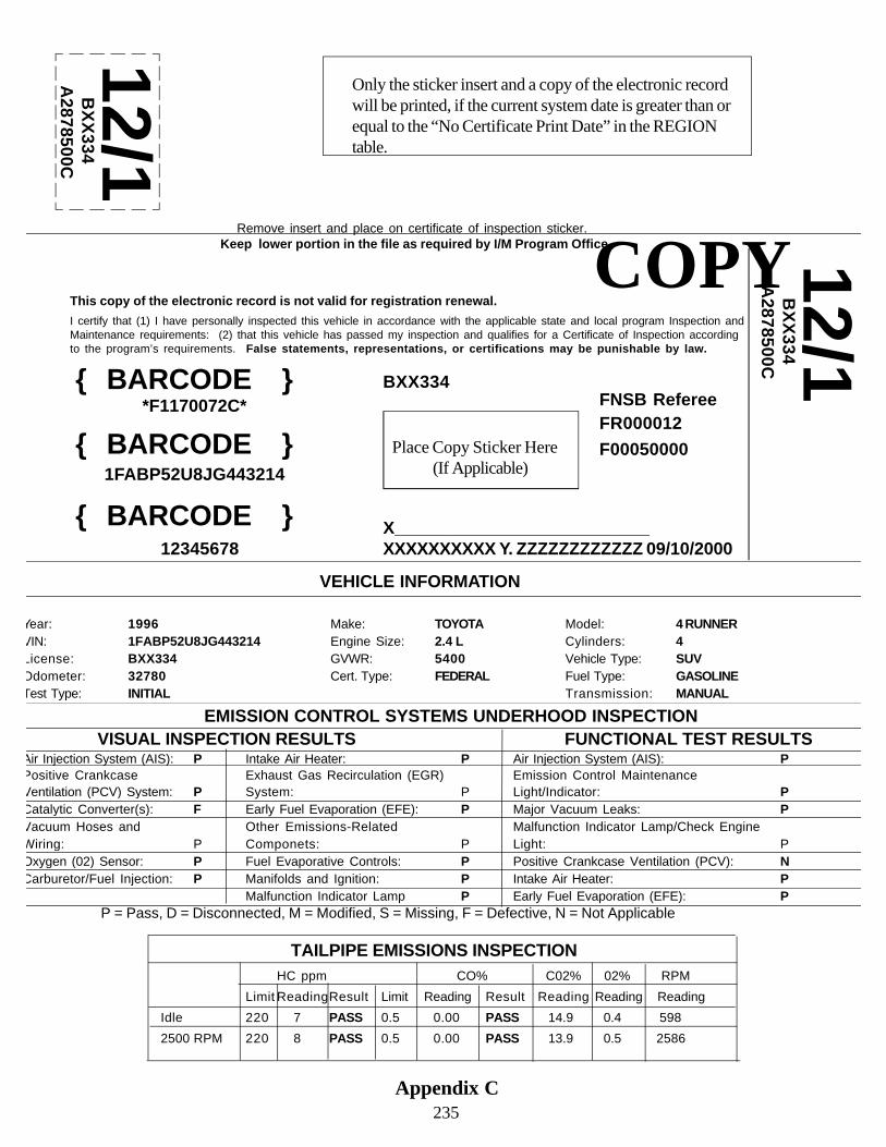
I certify that (1) I have personally inspected this vehicle in accordance with the applicable state and local program Inspection andMaintenance requirements: (2) that this vehicle has passed my inspection and qualifies for a Certificate of Inspection accordingto the program’s requirements. False statements, representations, or certifications may be punishable by law.
{ BARCODE }*F1170072C*
{ BARCODE }1FABP52U8JG443214
{ BARCODE } X__________________________XXXXXXXXXX Y. ZZZZZZZZZZZZ 09/10/2000
BXX334
12345678
COPY
Place Copy Sticker Here(If Applicable)
This copy of the electronic record is not valid for registration renewal.
FNSB RefereeFR000012F00050000
12/1B
XX
334A
2878500C
Only the sticker insert and a copy of the electronic recordwill be printed, if the current system date is greater than orequal to the “No Certificate Print Date” in the REGIONtable.
12/1B
XX
334A
2878500C
Remove insert and place on certificate of inspection sticker. Keep lower portion in the file as required by I/M Program Office.
VEHICLE INFORMATION
Year: 1996 Make: TOYOTA Model: 4 RUNNERVIN: 1FABP52U8JG443214 Engine Size: 2.4 L Cylinders: 4License: BXX334 GVWR: 5400 Vehicle Type: SUVOdometer: 32780 Cert. Type: FEDERAL Fuel Type: GASOLINETest Type: INITIAL Transmission: MANUAL
EMISSION CONTROL SYSTEMS UNDERHOOD INSPECTION VISUAL INSPECTION RESULTS FUNCTIONAL TEST RESULTSAir Injection System (AIS): P Intake Air Heater: P Air Injection System (AIS): PPositive Crankcase Exhaust Gas Recirculation (EGR) Emission Control MaintenanceVentilation (PCV) System: P System: P Light/Indicator: PCatalytic Converter(s): F Early Fuel Evaporation (EFE): P Major Vacuum Leaks: PVacuum Hoses and Other Emissions-Related Malfunction Indicator Lamp/Check EngineWiring: P Componets: P Light: POxygen (02) Sensor: P Fuel Evaporative Controls: P Positive Crankcase Ventilation (PCV): NCarburetor/Fuel Injection: P Manifolds and Ignition: P Intake Air Heater: P
Malfunction Indicator Lamp P Early Fuel Evaporation (EFE): PP = Pass, D = Disconnected, M = Modified, S = Missing, F = Defective, N = Not Applicable
TAILPIPE EMISSIONS INSPECTIONHC ppm CO% C02% 02% RPM
Limit ReadingResult Limit Reading Result Reading Reading Reading
Idle 220 7 PASS 0.5 0.00 PASS 14.9 0.4 598
2500 RPM 220 8 PASS 0.5 0.00 PASS 13.9 0.5 2586
235Appendix C

1. Certificate begins printing 0.45” from top of page with 0.45” margin on left side.2. Certificate is 3.0” long (from top of page).3. Certificate is 7.0” wide (from left hand edge of page).4. Sticker Insert begins printing 0.45” from top of page, 7.06” from left side of paper.5. Sticker Insert is 3.0” long (from top of page).6. Sticker Insert is 1.5” wide.7. The certificate number must be barcoded (0.25” height) 0.625” from left edge of paper.8. The certificate number must be printed in readable characters, Arial bold, font size 12, and 1.25” from left edge of paper.9. The VIN must be barcoded (0.25” height) 0.625” from left edge of paper.10. The VIN must be printed in readable characters, Arial bold, font size 12, 1.25” from left edge of paper.11. The license plate number must be barcoded (0.25” height) 0.625” from left edge of paper.12. The license plate number must be printed in readable characters, Arial bold, font size 12, and 1.25” from left edge of paper.13. The certified I/M station name, certified I/M station number, certified I/M mechanic name and certified mechanic number and test date (mo/da/year) must be in readable characters, Arial bold, font size 12, as shown on example; at 3.5” from left edge of paper, the line for the I/M mechanic’s signature, and the words “Certified I/M Mechanic” shall start at 5.375” from left edge of paper, the I/M station name and number and the I/M mechanic name and number must start at 5.75 the date of the I/M test must start.14. Font must be Arial, sizes as follows for the rest of the certificate:
top line “Important: Retain.....” : size 9; 2nd line “Alaska2000....”: size 11 bold; 3rd line “This certificate is valid...”: size 9 bold; 4th, 5th, and partial 6th line “I Certify.....”: size 8;end of 6th line “False statements....”: size 8 bold.
15. Sticker insert section: plate #, small font; large EIS-assigned expiration year ; large EIS-assigned expiration month; security code – to be determined.
16. An area must be identified for validation sticker, size is dependent upon length of VIN barcode, see example shown for relative size and placement.17. A dotted line must be printed between the certificate/sticker insert and their duplicated. All other dotted lines are for illustration only.18. Copy/Duplicate of Certificate of Inspection and Sticker insert.
A copy of the certificate of inspection and sticker insert as described above must be reproduced directly belowas shown in the example.The phrase “Tear off above portion and give to vehicle owner. Keep lower portion in file for 2 years with VIR copy.” replaces“Important: Retain this document with your vehicle registration.”
The word “COPY” must be printed across the duplicated certificate and sticker insert. Example shows Arial 65bold all caps.The sticker insert must only have EIS-assigned expiration month/year displayed.
Certificate of Inspection
Specifications
236Appendix C

Sticker Insert1. The EIS should print the sticker insert in the upper left corner as illustrated in the example. The text in the ex-
ample “Only the sticker insert will be printed...” should not be printed.2. The dotted line surrounding the sticker insert area is for illustration only.4. The insert information must be printed within a 1.0” by 1.5” area5. The insert area identified, in the example, by a dashed box must be 0.5” from the top edge of the paper and
0.5” from the left edge of the paper.6. The sticker insert must only have EIS-assigned expiration month/year displayed in following format MM/Y.7. For the sticker insert “Y”, the EIS-assigned expiration year, the single digit must be the last digit of the year.8. The MM/Y must be printed in Ariel, bold, 48 pt..9. The license plate number must be printed in Ariel, bold, 12 pt.10. The sticker number must be printed in Ariel, bold, 12 pt.
Copy of Electronic Record1. The EIS will use the templete established for the exmples given on pages 231 and 233 with regards to format. However, please note the following sentences and their location, which differs from the previous format. “Remove insert and place on certificate of inspection sticker. Keep lower portion in the file as required by I/M Program Office.” And “This copy of the electronic record is not valid for registration renewal.”2. Use the format, information, font sizes, as shown in the Appendix D, VIR examples, for each specific test. Forthose portions of the electronic record copy that begins with “VEHICLE INFORMATION.”
Insert
Specifications
Only the sticker insert will be printed, if the current systemdate is greater than or equal to the “No Certificate PrintDate” in the REGION table.
Appendix C237

238
Appendix D
Vehicle Inspection Reports

239
VIN: (BAR CODE)ALASKA VEHICLE INSPECTION REPORT
The I/M Program is improving air quality. Thank you for helping. RRN: (BAR CODE)Test Date/Time: 10/12/98 @ 08:51 12345678
Congratulations! Your vehicle passed the inspection. TIN:
The Certificate of Inspection is valid for registration renewal for 90 days from its date of issue.
Certificate of Inspection #: F1170072
VEHICLE INFORMATION
Year: 1996 Make: TOYOTA Model: 4 RUNNERVIN: JT3RN37XXXXXXXXXX Engine Size: 2.4 L Cylinders: 4License: CSAXXX GVWR: 5400 Vehicle Type: SUVOdometer: 32780 Cert. Type: FEDERAL Fuel Type: GASOLINETest Type: INITIAL Transmission: MANUAL
EMISSION CONTROL SYSTEMS UNDERHOOD INSPECTION
VISUAL INSPECTION RESULTS FUNCTIONAL TEST RESULTSAir Injection System (AIS): P Intake Air Heater: P Air Injection System (AIS): PPositive CrankcaseVentilation (PCV) System: P
Exhaust Gas Recirculation (EGR)System: P
Emission Control MaintenanceLight/Indicator: P
Catalytic Converter(s): P Early Fuel Evaporation (EFE): P Major Vacuum Leaks: PVacuum Hoses andWiring: P
Other Emissions-RelatedComponents: N
Malfunction Indicator Lamp/Check EngineLight: P
Oxygen (02) Sensor: P Fuel Evaporative Controls: P Positive Crankcase Ventilation (PCV): NCarburetor/Fuel Injection: P Manifolds and Ignition: P Intake Air Heater: P
Malfunction Indicator Lamp P Early Fuel Evaporation (EFE): PP = Pass, D = Disconnected, M = Modified, S = Missing, F = Defective, N = Not Applicable
TAILPIPE EMISSIONS INSPECTION
HC ppm CO% C02% 02% RPMLimit Reading Result Limit Reading Result Reading Reading Reading
Idle 220 7 PASS 0.5 0.00 PASS 14.9 0.4 5982500 RPM 220 8 PASS 0.5 0.00 PASS 13.9 0.5 2586
OVERALL TEST RESULT: PASS
Visual: PASS Functional: PASS Tailpipe Emissions: PASS OBD: PASS
I certify that (1) I have personally inspected this vehicle in accordance with applicable state and local program Inspectionand Maintenance requirements; (2) this vehicle has passed my inspection and qualifies for a Certificate of Inspectionaccording to the program’s requirements; and (3) the information listed on this report is true and correct.
Warning: False statements, representations, or certifications may be punishable by law.
Certified I/M Mechanic’s Signature_______________________________________________________ I/M Mechanic Name: XXXXXXXXXXXXXXX Y. ZZZZZZZZZZZZZZZZZZZZZZZZZZZZZZ
I/M Mechanic ID: XXXXXXXX
STATION INFORMATION
Station Name: Fairbanks North Star Borough Referee Station Phone: 907-459-1005Station Address: 3175 Peger Rd. Station Number: FT00012S
Analyzer #: BA090425Station City: Fairbanks, AK 99709 Software Version: 1.00
Appendix D.1VIR-PassingBasic Example

240
VIN: (BAR CODE)ALASKA VEHICLE INSPECTION REPORT
The I/M Program is improving air quality. Thank you for helping. RRN: (BAR CODE)Test Date/Time: 10/12/98 @ 08:51 12345678
VEHICLE INFORMATION
Year: 1996 Make: TOYOTA Model: 4 RUNNERVIN: JT3RN37XXXXXXXXXX Engine Size: 2.4 L Cylinders: 4License: CSAXXX GVWR: 5400 Vehicle Type: SUVOdometer 32780 Cert. Type: FEDERAL Fuel Type: GASOLINETest Type: INITIAL Transmission: MANUAL
EMISSION CONTROL SYSTEMS UNDERHOOD INSPECTION
VISUAL INSPECTION RESULTS FUNCTIONAL TEST RESULTSAir Injection System (AIS): P Intake Air Heater: P Air Injection System (AIS): PPositive CrankcaseVentilation (PCV) System: P
Exhaust Gas Recirculation (EGR)System: P
Emission Control MaintenanceLight/Indicator: P
Catalytic Converter(s): P Early Fuel Evaporation (EFE): P Major Vacuum Leaks: PVacuum Hoses andWiring: P
Other Emissions-RelatedComponents: N
Malfunction Indicator Lamp/Check EngineLight: F
Oxygen (02) Sensor: P Fuel Evaporative Controls: P Positive Crankcase Ventilation (PCV): PCarburetor/Fuel Injection: P Manifolds and Ignition: P Intake Air Heater: P
Malfunction Indicator Lamp P Early Fuel Evaporation (EFE): PP = Pass, D = Disconnected, M = Modified, S = Missing, F = Defective, N = Not Applicable
TAILPIPE EMISSIONS INSPECTION
HC ppm CO% C02% 02% RPMLimit Reading Result Limit Reading Result Reading Reading Reading
Idle 220 7 PASS 0.5 0.00 PASS 14.9 0.4 598
2500 RPM 220 8 PASS 0.5 0.00 PASS 13.9 0.5 2586
OVERALL TEST RESULT: FAILVisual: Pass Functional: FAIL Tailpipe Emissions : PASS OBD: PASS
Your vehicle failed the inspection because of missing, disconnected, defective or modified emission control equipment. Forfurther information or assistance, please contact the referee facility.
WARRANTY MESSAGE (For Applicable Vehicles)Please check with your authorized dealer for emission control warranty details. All vehicles that may be eligible for
warranty repair shall be referred to the Authorized Dealer.Vehicles with disconnected, modified, or missing emissions control devices require repair, regardless of cost.Only those repairs made by a certified I/M mechanic, after an initial inspection is performed, will be considered for a
repair cost waiver. If you need additional assistance, contact the local I/M program office.
I certify that (1) I have personally inspected this vehicle in accordance with applicable state and local program Inspectionand Maintenance requirements: and (2) the information listed on this report is true and correct.
Warning: False statements, representations, or certifications may be punishable by law.
Certified I/M Mechanic’s Signature_______________________________________________________I/M Mechanic Name: XXXXXXXXXXXXXXX Y. ZZZZZZZZZZZZZZZZZZZZZZZZZZZZZZI/M Mechanic ID: XXXXXXXX
STATION INFORMATION
Station Name: Fairbanks North Star Borough Referee Station Phone: 907-459-1005Station Address: 3175 Peger Rd. Station Number: FT00012S
Analyzer #: BA090425Station City: Fairbanks, AK 99709 Software Version: 1.00
Appendix D.2VIR-FailingBasic Example

241
VIN: (BAR CODE)ALASKA VEHICLE INSPECTION REPORT
Continued RRN: (BAR CODE)Test Date/Time: 10/01/98 @ 07:43 12345678
ADVISORY
Please be advised your vehicle did not pass the on-board diagnostic system (OBD) test. The purpose of the OBD system isto assure proper emission control system operation for the vehicle’s lifetime by monitoring emission-related componentsand systems for deterioration and malfunction.
Specifically, your vehicle’s OBD failed for the following reason(s):
While this is an advisory at this time, if your vehicle remains in this condition, it could result in an I/M testfailure in the future.
If your vehicle is still under warranty, please contact the Authorized Dealer for repair, if not, contact a CertifiedI/M Test & Repair Facility. Proper maintenance and timely repairs will extend the life of your engine, assuregood fuel economy and reduce air pollution.
Appendix D.3AVIR-ContinuationPage. To be used witheither Passing orFailing VIR if OBDportion fails. To beused prior to date setwhen OBD testfailure results inOverall Test Failure.
Display VIR messages located in the OBD_Exemptions_Cursor procedure’s VIR_Msg field foroffline tests and in the Vehicle_Data procedure’s OBD_VIR_Message field for online tests. Onlydisplay message if field(s) are populated for specific make, model and model year of vehicle beingtested. Text box will expand to accommodate message length. Message will not wrap to additionalpages. Text box of displayed messages will be dashed or enclosed by lines.

242
VIN: (BAR CODE)ALASKA VEHICLE INSPECTION REPORT
Continued RRN: (BAR CODE)Test Date/Time: 10/01/98 @ 07:43 12345678
Appendix D.3BVIR-Continuation Page.To be used with D.2 whenOBD portion fails andresults in an Overall TestFailure andvisual/functional testwas performed.
Display VIR messages located in the OBD_Exemptions table VIR_Msg field.. Only displaymessage if field(s) are populated for specific make, model and model year of vehicle being tested.Text box will expand to accommodate message length. Message will not wrap to additional pages.Text box of displayed messages will be dashed or enclosed by lines.
Display appropriate VIR message located in Overall OBDII Result, B. VIR Messages, according tospecific testing result or condition.

243
VIN: (BAR CODE)ALASKA VEHICLE INSPECTION REPORT
The I/M Program is improving air quality. Thank you for helping. RRN: (BAR CODE)Test Date/Time: 10/12/98 @ 08:51 12345678
TIN:Congratulations! Your vehicle passed the inspection.
The Certificate of Inspection is valid for registration renewal for 90 days from its date of issue.
Certificate of Inspection #: F1170072
VEHICLE INFORMATION
Year: 1996 Make: TOYOTA Model: 4 RUNNERVIN: JT3RN37XXXXXXXXXX Engine Size: 2.4 L Cylinders: 4License: CSAXXX GVWR: 5400 Vehicle Type: SUVOdometer: 32780 Cert. Type: FEDERAL Fuel Type: GASOLINETest Type: INITIAL Transmission: MANUAL
EMISSION CONTROL SYSTEMS UNDERHOOD INSPECTION
VISUAL INSPECTION RESULTS FUNCTIONAL TEST RESULTSAir Injection System (AIS): P Intake Air Heater: P Air Injection System (AIS): PPositive CrankcaseVentilation (PCV) System: P
Exhaust Gas Recirculation (EGR)System: P
Emission Control MaintenanceLight/Indicator: P
Catalytic Converter(s): P Early Fuel Evaporation (EFE): P Major Vacuum Leaks: PVacuum Hoses andWiring: P
Other Emissions-RelatedComponents: N
Malfunction Indicator Lamp/Check EngineLight: P
Oxygen (02) Sensor: P Fuel Evaporative Controls: P Positive Crankcase Ventilation (PCV): NCarburetor/Fuel Injection: P Manifolds and Ignition: P Intake Air Heater: P
Malfunction Indicator Lamp P Early Fuel Evaporation (EFE): PP = Pass, D = Disconnected, M = Modified, S = Missing, F = Defective, N = Not Applicable
TAILPIPE EMISSIONS INSPECTION
HC ppm CO% C02% 02% RPMLimit Reading Result Limit Reading Result Reading Reading Reading
Idle 220 7 PASS 0.5 0.00 PASS 14.9 0.4 5982500 RPM 220 8 PASS 0.5 0.00 PASS 13.9 0.5 2586
OVERALL TEST RESULT: PASSVisual: PASS Functional: PASS Tailpipe Emissions: PASS OBD: PASS
Repair Actions: A “Yes” indicates: Checked, repaired, replaced, or adjusted. A “W” indicates under Warranty.EGR System Yes Exhaust System No Internal Engine NoElectrical/Electronic System No Ignition System No PCV System NoEvaporative Control System No Intake/Fuel Induction System No Other No
Total Cost of Repairs (Parts & Labor) Performed: $407
I certify that (1) I have personally inspected this vehicle in accordance with applicable state and local program Inspectionand Maintenance requirements; (2) that this vehicle has passed my inspection and qualifies for a Certificate of Inspectionaccording to the program’s requirements: and (3) the information listed on this report is true and correct.
Warning: False statements, representations, or certifications may be punishable by law.
Certified I/M Mechanic’s Signature_______________________________________________________I/M Mechanic Name: XXXXXXXXXXXXXXX Y. ZZZZZZZZZZZZZZZZZZZZZZZZZZZZZZI/M Mechanic ID: XXXXXXXX
STATION INFORMATION
Station Name: Fairbanks North Star Borough Referee Station Phone: 907-459-1005Station Address: 3175 Peger Rd. Station Number: FT00012S
Analyzer #: BA090425Station City: Fairbanks, AK 99709 Software Version: 1.00
Appendix D.4VIR-After repairs-pass, Basic Example

244
VIN: (BAR CODE)ALASKA VEHICLE INSPECTION REPORT
The I/M Program is improving air quality. Thank you for helping. RRN: (BAR CODE)Test Date/Time: 10/12/98 @ 08:51 12345678
(i) INCOMPLETE INSPECTION
VEHICLE INFORMATION
Year: 1996 Make: TOYOTA Model: 4 RUNNERVIN: JT3RN37XXXXXXXXXX Engine Size: 2.4 L Cylinders: 4License: CSAXXX GVWR: 5400 Vehicle Type: SUVOdometer: 32780 Cert. Type: FEDERAL Fuel Type: GASOLINETest Type: INITIAL Transmission: MANUAL
EMISSION CONTROL SYSTEMS UNDERHOOD INSPECTION
VISUAL INSPECTION RESULTS FUNCTIONAL TEST RESULTSAir Injection System (AIS): P Intake Air Heater: P Air Injection System (AIS): PPositive CrankcaseVentilation (PCV) System: P
Exhaust Gas Recirculation (EGR)System: P
Emission Control MaintenanceLight/Indicator: P
Catalytic Converter(s): P Early Fuel Evaporation (EFE): P Major Vacuum Leaks: PVacuum Hoses andWiring: P
Other Emissions-RelatedComponents: N
Malfunction Indicator Lamp/Check EngineLight: N
Oxygen (02) Sensor: P Fuel Evaporative Controls: P Positive Crankcase Ventilation (PCV): N/ACarburetor/Fuel Injection: P Manifolds and Ignition: P Intake Air Heater: P
Malfunction Indicator Lamp P Early Fuel Evaporation (EFE): PP = Pass, D = Disconnected, M = Modified, S = Missing, F = Defective, N = Not Applicable
TAILPIPE EMISSIONS INSPECTION
HC ppm CO% C02% 02% RPMLimit Reading Result Limit Reading Result Reading Reading Reading
Idle 220 ABORTED ABORTED 0.5 ABORTED ABORTED ABORTED ABORTED 5982500 RPM 220 ABORTED ABORTED 0.5 ABORTED ABORTED ABORTED ABORTED 2596
OVERALL TEST RESULT: ABORTED
Visual: ABORTED Functional: ABORTED Tailpipe Emissions: ABORTED OBD: ABORTED
The Official I/M Test Was Aborted for the Following Reason(s):
Abort Code Abort Description
I certify that (1) I have personally inspected this vehicle in accordance with applicable state and local program Inspectionand Maintenance requirements; (2) the information listed on this report is true and correct.
Warning: False statements, representations, or certifications may be punishable by law.
Certified I/M Mechanic’s Signature_______________________________________________________I/M Mechanic Name: XXXXXXXXXXXXXXX Y. ZZZZZZZZZZZZZZZZZZZZZZZZZZZZZZI/M Mechanic ID: XXXXXXXX
STATION INFORMATION
Station Name: Fairbanks North Star Borough Referee Station Phone: 907-459-1005Station Address: 3175 Peger Rd. Station Number: FT00012S
Analyzer #: BA090425Station City: Fairbanks, AK 99709 Software Version: 1.00
Appendix D.5VIR-AbortBasic Example

245
VIN: (BAR CODE)ALASKA VEHICLE INSPECTION REPORT
Continued RRN: (BAR CODE)Test Date/Time: 10/01/98 @ 07:43 12345678
Please be advised that your vehicle inspection could not be completed at this time. Your vehicle’s on-board diagnostic(OBD) system was not able to complete a readiness evaluation. In order to demonstrate a “ready” condition the vehiclemust be operated in a specific driving pattern. Your vehicle must demonstrate a “ready” condition prior to being tested sothat test results are accurate. The purpose of the OBD system is to assure proper emission control system operation for thevehicle’s lifetime by monitoring emission-related components and systems for deterioration and malfunction.
Specifically, your vehicle emission control systems not in a “ready” condition are:
Please contact your appropriate vehicle dealership for assistance in determining your vehicle’s operatingcondition that must be accomplished in order to set the above code(s). When your vehicle has met the conditionslisted above please return for an inspection. If you have questions concerning your vehicle’s OBD system pleasecontact your authorized service dealer for specific information.
Appendix D.5AVIR-Continuation Page.To be used with an abortdue to an incompleteOBD readiness

246
ALASKA VEHICLE INSPECTION REPORTThe I/M Program is improving air quality. Thank you for helping. RRN: (BAR CODE)
Test Date/Time: 10/12/98 @ 08:51 12345678
TIN: VOID
TRAINING TEST
VEHICLE INFORMATION
Year: 1985 Make: FORD Model: F150VIN: 2FTEF14N9FCB47189 Engine Size: 5.0L Cylinders: 8License: 7895CD GVWR: 5999 Vehicle Type: PICKUPOdometer: 122611 Cert. Type: FEDERAL Fuel Type: GASOLINETest Type: INITIAL Transmission: AUTOMATIC
EMISSION CONTROL SYSTEMS UNDERHOOD INSPECTION
VISUAL INSPECTION RESULTS FUNCTIONAL TEST RESULTSAir Injection System (AIS): P Intake Air Heater: P Air Injection System (AIS): PPositive CrankcaseVentilation (PCV) System: P
Exhaust Gas Recirculation (EGR)System: P
Emission Control MaintenanceLight/Indicator: P
Catalytic Converter(s): P Early Fuel Evaporation (EFE): P Major Vacuum Leaks: PVacuum Hoses andWiring: P
Other Emissions-RelatedComponents: N
Malfunction Indicator Lamp/Check EngineLight: P
Oxygen (02) Sensor: P Fuel Evaporative Controls: P Positive Crankcase Ventilation (PCV): NCarburetor/Fuel Injection: P Manifolds and Ignition: P Intake Air Heater: P
Malfunction Indicator Lamp P Early Fuel Evaporation (EFE): PP = Pass, D = Disconnected, M = Modified, S = Missing, F = Defective, N = Not Applicable
TAILPIPE EMISSIONS INSPECTION
HC ppm CO% C02% 02% RPMLimit Reading Result Limit Reading Result Reading Reading Reading
Idle 220 7 PASS 0.5 0.00 PASS 14.9 0.4 5982500 RPM 220 8 PASS 0.5 0.00 PASS 13.9 0.5 2586
OVERALL TEST RESULT: INVALID
Visual: PASS Functional: PASS Tailpipe Emissions: PASS OBD: PASS
I certify that (1) I have personally inspected this vehicle in accordance with applicable state and local program Inspectionand Maintenance requirements; ((2) the information listed on this report is true and correct.
Warning: False statements, representations, or certifications may be punishable by law.
Certified I/M Mechanic’s Signature_______________________________________________________I/M Mechanic Name: XXXXXXXXXXXXXXX Y. ZZZZZZZZZZZZZZZZZZZZZZZZZZZZZZI/M Mechanic ID: XXXXXXXX
STATION INFORMATION
Station Name: Fairbanks North Star Borough Referee Station Phone: 907-459-1005Station Address: 3175 Peger Rd. Station Number: FT00012S
Analyzer #: BA090425Station City: Fairbanks, AK 99709 Software Version: 1.00
Appendix D.6VIR-TrainingBasic Example
In “TRAININGMODE” no certificatenumber will beentered or printed.
The “VOID” will appearbelow the emissioninformation so thattraining test results maybe readable.
VIN: (BAR CODE)

247
VIN: (BAR CODE)ALASKA VEHICLE INSPECTION REPORT
The I/M Program is improving air quality. Thank you for helping. RRN: (BAR CODE)Test Date/Time: 10/12/98 @ 08:51 12345678
TIN:
The Certificate of Inspection is valid for registration renewal for 90 days from its date of issue.
Certificate of Inspection #: F1170072
VEHICLE INFORMATION
Year: 1996 Make: TOYOTA Model: 4 RUNNERVIN: JT3RN37XXXXXXXXXX Engine Size: 2.4 L Cylinders: 4License: CSAXXX GVWR: 5400 Vehicle Type: SUVOdometer: 32780 Cert. Type: FEDERAL Fuel Type: GASOLINETest Type: INITIAL Transmission: MANUAL
EMISSION CONTROL SYSTEMS UNDERHOOD INSPECTIONVISUAL INSPECTION RESULTS FUNCTIONAL TEST RESULTS
Air Injection System (AIS): P Intake Air Heater: P Air Injection System (AIS): PPositive CrankcaseVentilation (PCV) System: P
Exhaust Gas Recirculation (EGR)System: P
Emission Control MaintenanceLight/Indicator: P
Catalytic Converter(s): F Early Fuel Evaporation (EFE): P Major Vacuum Leaks: PVacuum Hoses andWiring: P
Other Emissions-RelatedComponents: P
Malfunction Indicator Lamp/Check EngineLight: P
Oxygen (02) Sensor: P Fuel Evaporative Controls: P Positive Crankcase Ventilation (PCV): NCarburetor/Fuel Injection: P Manifolds and Ignition: P Intake Air Heater: P
Malfunction Indicator Lamp P Early Fuel Evaporation (EFE): PP = Pass, D = Disconnected, M = Modified, S = Missing, F = Defective, N = Not Applicable
TAILPIPE EMISSIONS INSPECTIONHC ppm CO% C02% 02% RPM
Limit Reading Result Limit Reading Result Reading Reading ReadingIdle 220 7 PASS 0.5 0.00 PASS 14.9 0.4 598
2500 RPM 220 8 PASS 0.5 0.00 PASS 13.9 0.5 2586
OVERALL TEST RESULT: REFEREE OVERRIDE
Visual: OVERRIDE Functional: PASS Tailpipe Emissions : PASS OBD: PASS
Reason for certification
Repair Actions:A “Yes” indicates: Checked, repaired, replaced, or adjusted. A “W” indicates under Warranty. An “O” indicates override.EGR System Yes Exhaust System O Internal EngineElectrical/Electronic System Ignition System Yes PCV SystemEvaporative Control System Intake/Fuel Induction System Other
Total Cost of Repairs (Parts & Labor) Performed: $457
Appendix D.7VIR-Referee OverrideBasic Result

248
- - - - - - - - - - - - - - - - -INCOMPLETE REPORT WITHOUT 2ND PAGE - - - - - - - - - - - - - - - - - - -PAGE 1 OF 2
VIN: (BAR CODE)ALASKA VEHICLE INSPECTION REPORT
The I/M Program is improving air quality. Thank you for helping. RRN: (BARCODE)
Test Date/Time: 10/12/98 @ 08:51 12345678
WARRANTY MESSAGE (For Applicable Vehicles)Please check with your authorized dealer for emission control warranty details. All vehicles that
may be eligible for warranty repair shall be referred to the authorized dealer.All vehicles with disconnected, modified, or missing emissions control devices require repair
regardless of cost.Only those repairs made by a certified I/M mechanic, after an initial inspection is performed, will
be considered for a repair cost waiver. If you need additional assistance, contact the local I/M programoffice.
I certify that (1) I have personally inspected this vehicle in accordance with applicable state and localprogram Inspection and Maintenance requirements; (2) that this vehicle has passed my inspection andqualifies for a Certificate of Inspection according to the program’s requirements: and (3) the informationlisted on this report is true and correct.
Warning: False statements, representations, or certifications may be punishable by law.
Certified I/M Mechanic’s Signature______________________________________________________I/M Mechanic Name: XXXXXXXXXXXXXXX Y. ZZZZZZZZZZZZZZZZZZZZZZZZZZZZZZI/M Mechanic ID: XXXXXXXX
STATION INFORMATIONStationName:
Fairbanks North Star BoroughReferee Station Phone: 907-459-1005
StationAddress:
3175 Peger Rd. Station Number: FT00012S
Analyzer #: BA090425Station City: Fairbanks, AK 99709 Software
Version:1.00
- - - - - - - - - - - - - - - - -INCOMPLETE REPORT WITHOUT 1ST PAGE - - - - - - - - - - - - - - - - - - -
PAGE 2 OF 2

249
ADVISORY
During the emissions inspection test on your vehicle there were technical difficulties withcommunications, and your vehicle’s electronic test result has been delayed in its transfer. Therefore, there will bea delay before you may renew your vehicle registration by phone or Internet. Please wait 72 hours beforeattempting to use an electronic means of renewing your vehicle registration.
Appendix D.9No VID ContactAdvisory Basic Example
If the modem fails to receivean answer, receives a busysignal, or if inspection data isnot transferred to the VID inthe specified time.

250
ADVISORY
THE EMISSION CONTROL MAINTENANCE LIGHT/INDICATOR IS NOT FUNCTIONAL ORINDICATES THAT YOUR EMISSION CONTROL SYSTEM IS IN NEED OF A MANUFACTURER-RECOMMENDED SERVICE. MAINTAINING YOUR VEHICLE’S EMISSION CONTROL SYSTEMIS RECOMMENDED IN ORDER TO KEEP YOUR VEHICLE’S ENGINE RUNNING PROPERLY,MAINTAIN FUEL ECONOMY AND HELP REDUCE AIR POLLUTION.
Appendix D.10MiscellaneousAdvisory BasicExample
To be used as an advisory tothe motorist when the vehiclepasses the I/M test but someproblem is noted with thevehicle during the test.

251
VIN: (BAR CODE)ALASKA VEHICLE INSPECTION REPORT
The I/M Program is improving air quality. Thank you for helping. RRN: (BAR CODE)Test Date/Time: 10/12/98 @ 08:51 12345678
VEHICLE INFORMATION
Year: 1996 Make: TOYOTA Model: 4 RUNNERVIN: JT3RN37XXXXXXXXXX Engine Size: 2.4 L Cylinders: 4License: CSAXXX GVWR: 5400 Vehicle Type: SUVOdometer: 32780 Cert. Type: FEDERAL Fuel Type: GASOLINETest Type: INITIAL Transmission: MANUAL
OVERALL TEST RESULT: _____
I certify that (1) I have personally inspected this vehicle in accordance with applicable state and local program Inspectionand Maintenance requirements; (2) this vehicle has passed my inspection and qualifies for a Certificate of Inspectionaccording to the program’s requirements; and (3) the information listed on this report is true and correct.
Warning: False statements, representations, or certifications may be punishable by law.
Certified I/M Mechanic’s Signature_______________________________________________________ I/M Mechanic Name: XXXXXXXXXXXXXXX Y. ZZZZZZZZZZZZZZZZZZZZZZZZZZZZZZ
I/M Mechanic ID: XXXXXXXX
STATION INFORMATION
Station Name: Fairbanks North Star Borough Referee Station Phone: 907-459-1005Station Address: 3175 Peger Rd. Station Number: FT00012S
Analyzer #: BA090425Station City: Fairbanks, AK 99709 Software Version: 1.00
AppendixD11VIR-OBDW/O Visual& functionaltestBasicExample
Display VIR messages located in the OBD_Exemption table VIR_Msg field. Only display messageif field(s) are populated for specific make, model and model year of vehicle being tested. Text boxwill expand to accommodate message length. Message will not wrap to additional pages. Text boxof displayed messages will be dashed or enclosed by lines.
Display appropriate VIR message located in Overall OBDII Result, B. VIR Messages, according tospecific testing result or condition.

252
VIN: (BAR CODE)ALASKA VEHICLE INSPECTION REPORT
The I/M Program is improving air quality. Thank you for helping. RRN: (BAR CODE)Test Date/Time: 10/12/98 @ 08:51 12345678
VEHICLE INFORMATION
Year: 1996 Make: TOYOTA Model: 4 RUNNERVIN: JT3RN37XXXXXXXXXX Engine Size: 2.4 L Cylinders: 4License: CSAXXX GVWR: 5400 Vehicle Type: SUVOdometer: 32780 Cert. Type: FEDERAL Fuel Type: GASOLINETest Type: INITIAL Transmission: MANUAL
OVERALL TEST RESULT: _____
Repair Actions: A “Yes” indicates: Checked, repaired, replaced, or adjusted. A “W” indicates under Warranty.EGR System Yes Exhaust System No Internal Engine NoElectrical/Electronic System No Ignition System No PCV System NoEvaporative Control System No Intake/Fuel Induction System No Other No
Total Cost of Repairs (Parts & Labor) Performed: $407
I certify that (1) I have personally inspected this vehicle in accordance with applicable state and local program Inspectionand Maintenance requirements; (2) this vehicle has passed my inspection and qualifies for a Certificate of Inspectionaccording to the program’s requirements; and (3) the information listed on this report is true and correct.
Warning: False statements, representations, or certifications may be punishable by law.
Certified I/M Mechanic’s Signature_______________________________________________________ I/M Mechanic Name: XXXXXXXXXXXXXXX Y. ZZZZZZZZZZZZZZZZZZZZZZZZZZZZZZ
I/M Mechanic ID: XXXXXXXX
STATION INFORMATION
Station Name: Fairbanks North Star Borough Referee Station Phone: 907-459-1005Station Address: 3175 Peger Rd. Station Number: FT00012S
Analyzer #: BA090425Station City: Fairbanks, AK 99709 Software Version: 1.00
AppendixD12VIR-OBDW/O Visual& functionaltestAfter-RepairBasicExample
Display VIR messages located in the OBD_Exemption table VIR_Msg field. Only display messageif field(s) are populated for specific make, model and model year of vehicle being tested. Text boxwill expand to accommodate message length. Message will not wrap to additional pages. Text boxof displayed messages will be dashed or enclosed by lines.
Display appropriate VIR message located in Overall OBDII Result, B. VIR Messages, according tospecific testing result or condition.

253
VIN: (BAR CODE)ALASKA VEHICLE INSPECTION REPORT
The I/M Program is improving air quality. Thank you for helping. RRN: (BAR CODE)Test Date/Time: 10/12/98 @ 08:51 12345678
Congratulations! Your vehicle passed the inspection.
The Certificate of Inspection is valid for registration renewal for 90 days from its date of issue.
Certificate of Inspection #: F1170072
VEHICLE INFORMATION
Year: 1995 Make: TOYOTA Model: 4 RUNNERVIN: JT3RN37XXXXXXXXXX Engine Size: 2.4 L Cylinders: 4License: CSAXXX GVWR: 5400 Vehicle Type: SUVOdometer: 32780 Cert. Type: FEDERAL Fuel Type: BI-FUELTest Type: INITIAL Transmission: MANUAL
EMISSION CONTROL SYSTEMS UNDERHOOD INSPECTION
VISUAL INSPECTION RESULTS FUNCTIONAL TEST RESULTSAir Injection System (AIS): P Intake Air Heater: P Air Injection System (AIS): PPositive CrankcaseVentilation (PCV) System: P
Exhaust Gas Recirculation (EGR)System: P
Emission Control MaintenanceLight/Indicator: P
Catalytic Converter(s): P Early Fuel Evaporation (EFE): P Major Vacuum Leaks: PVacuum Hoses andWiring: P
Other Emissions-RelatedComponents: N
Malfunction Indicator Lamp/Check EngineLight: P
Oxygen (02) Sensor: P Fuel Evaporative Controls: P Positive Crankcase Ventilation (PCV): NCarburetor/Fuel Injection: P Manifolds and Ignition: P Intake Air Heater: P
Malfunction Indicator Lamp P Early Fuel Evaporation (EFE): PP = Pass, D = Disconnected, M = Modified, S = Missing, F = Defective, N = Not Applicable
ALTERNATE FUEL MODE: TAILPIPE EMISSIONS INSPECTION
HC ppm CO% C02% 02% RPMLimit Reading Result Limit Reading Result Reading Reading Reading
Idle 220 7 PASS 0.5 0.00 PASS 14.9 0.4 5982500 RPM 220 8 PASS 0.5 0.00 PASS 13.9 0.5 2586
OVERALL TEST RESULT: PASS
I certify that (1) I have personally inspected this vehicle in accordance with applicable state and local program Inspectionand Maintenance requirements; (2) this vehicle has passed my inspection and qualifies for a Certificate of Inspectionaccording to the program’s requirements; and (3) the information listed on this report is true and correct.
Warning: False statements, representations, or certifications may be punishable by law.
Certified I/M Mechanic’s Signature_______________________________________________________ I/M Mechanic Name: XXXXXXXXXXXXXXX Y. ZZZZZZZZZZZZZZZZZZZZZZZZZZZZZZ
I/M Mechanic ID: XXXXXXXX
STATION INFORMATION
Station Name: Fairbanks North Star Borough Referee Station Phone: 907-459-1005Station Address: 3175 Peger Rd. Station Number: FT00012S
Analyzer #: BA090425Station City: Fairbanks, AK 99709 Software Version: 1.00
Appendix D.13VIR-PassingBasic Bi-FuelExample Page 1Alt. Fuel Page.=/< MY 1995

254
VIN: (BAR CODE)ALASKA VEHICLE INSPECTION REPORT
The I/M Program is improving air quality. Thank you for helping. RRN: (BAR CODE)Test Date/Time: 10/12/98 @ 08:51 12345678
Congratulations! Your vehicle passed the inspection.
The Certificate of Inspection is valid for registration renewal for 90 days from its date of issue.
Certificate of Inspection #: F1170072
VEHICLE INFORMATION
Year: 1995 Make: TOYOTA Model: 4 RUNNERVIN: JT3RN37XXXXXXXXXX Engine Size: 2.4 L Cylinders: 4License: CSAXXX GVWR: 5400 Vehicle Type: SUVOdometer: 32780 Cert. Type: FEDERAL Fuel Type: BI-FUELTest Type: INITIAL Transmission: MANUAL
EMISSION CONTROL SYSTEMS UNDERHOOD INSPECTION
VISUAL INSPECTION RESULTS FUNCTIONAL TEST RESULTSAir Injection System (AIS): P Intake Air Heater: P Air Injection System (AIS): PPositive CrankcaseVentilation (PCV) System: P
Exhaust Gas Recirculation (EGR)System: P
Emission Control MaintenanceLight/Indicator: P
Catalytic Converter(s): P Early Fuel Evaporation (EFE): P Major Vacuum Leaks: PVacuum Hoses andWiring: P
Other Emissions-RelatedComponents: N
Malfunction Indicator Lamp/Check EngineLight: P
Oxygen (02) Sensor: P Fuel Evaporative Controls: P Positive Crankcase Ventilation (PCV): NCarburetor/Fuel Injection: P Manifolds and Ignition: P Intake Air Heater: P
Malfunction Indicator Lamp P Early Fuel Evaporation (EFE): PP = Pass, D = Disconnected, M = Modified, S = Missing, F = Defective, N = Not Applicable
TAILPIPE EMISSIONS INSPECTION
HC ppm CO% C02% 02% RPMLimit Reading Result Limit Reading Result Reading Reading Reading
Idle 220 7 PASS 0.5 0.00 PASS 14.9 0.4 5982500 RPM 220 8 PASS 0.5 0.00 PASS 13.9 0.5 2586
OVERALL TEST RESULT: PASS
I certify that (1) I have personally inspected this vehicle in accordance with applicable state and local program Inspectionand Maintenance requirements; (2) this vehicle has passed my inspection and qualifies for a Certificate of Inspectionaccording to the program’s requirements; and (3) the information listed on this report is true and correct.
Warning: False statements, representations, or certifications may be punishable by law.
Certified I/M Mechanic’s Signature_______________________________________________________ I/M Mechanic Name: XXXXXXXXXXXXXXX Y. ZZZZZZZZZZZZZZZZZZZZZZZZZZZZZZ
I/M Mechanic ID: XXXXXXXX
STATION INFORMATION
Station Name: Fairbanks North Star Borough Referee Station Phone: 907-459-1005Station Address: 3175 Peger Rd. Station Number: FT00012S
Analyzer #: BA090425Station City: Fairbanks, AK 99709 Software Version: 1.00
Appendix D.14VIR-PassingBasic Bi-FuelExample Page 2Gasoline Page.=/< MY 1995

255
VIN: (BAR CODE)ALASKA VEHICLE INSPECTION REPORT
The I/M Program is improving air quality. Thank you for helping. RRN: (BAR CODE)Test Date/Time: 10/12/98 @ 08:51 12345678
Congratulations! Your vehicle passed the inspection.
The Certificate of Inspection is valid for registration renewal for 90 days from its date of issue.
Certificate of Inspection #: F1170072
VEHICLE INFORMATION
Year: 1996 Make: TOYOTA Model: 4 RUNNERVIN: JT3RN37XXXXXXXXXX Engine Size: 2.4 L Cylinders: 4License: CSAXXX GVWR: 5400 Vehicle Type: SUVOdometer: 32780 Cert. Type: FEDERAL Fuel Type: BI-FUELTest Type: INITIAL Transmission: MANUAL
EMISSION CONTROL SYSTEMS UNDERHOOD INSPECTION
VISUAL INSPECTION RESULTS FUNCTIONAL TEST RESULTSAir Injection System (AIS): P Intake Air Heater: P Air Injection System (AIS): PPositive CrankcaseVentilation (PCV) System: P
Exhaust Gas Recirculation (EGR)System: P
Emission Control MaintenanceLight/Indicator: P
Catalytic Converter(s): P Early Fuel Evaporation (EFE): P Major Vacuum Leaks: PVacuum Hoses andWiring: P
Other Emissions-RelatedComponents: N
Malfunction Indicator Lamp/Check EngineLight: P
Oxygen (02) Sensor: P Fuel Evaporative Controls: P Positive Crankcase Ventilation (PCV): NCarburetor/Fuel Injection: P Manifolds and Ignition: P Intake Air Heater: P
Malfunction Indicator Lamp P Early Fuel Evaporation (EFE): PP = Pass, D = Disconnected, M = Modified, S = Missing, F = Defective, N = Not Applicable
ALTERNATE FUEL MODE: TAILPIPE EMISSIONS INSPECTION
HC ppm CO% C02% 02% RPMLimit Reading Result Limit Reading Result Reading Reading Reading
Idle 220 7 PASS 0.5 0.00 PASS 14.9 0.4 5982500 RPM 220 8 PASS 0.5 0.00 PASS 13.9 0.5 2586
OVERALL TEST RESULT: PASS
Visual: PASS Functional: PASS Tailpipe Emissions: PASS OBD: PASS
I certify that (1) I have personally inspected this vehicle in accordance with applicable state and local program Inspectionand Maintenance requirements; (2) this vehicle has passed my inspection and qualifies for a Certificate of Inspectionaccording to the program’s requirements; and (3) the information listed on this report is true and correct.
Warning: False statements, representations, or certifications may be punishable by law.
Certified I/M Mechanic’s Signature_______________________________________________________ I/M Mechanic Name: XXXXXXXXXXXXXXX Y. ZZZZZZZZZZZZZZZZZZZZZZZZZZZZZZ
I/M Mechanic ID: XXXXXXXX
STATION INFORMATION
Station Name: Fairbanks North Star Borough Referee Station Phone: 907-459-1005Station Address: 3175 Peger Rd. Station Number: FT00012S
Analyzer #: BA090425Station City: Fairbanks, AK 99709 Software Version: 1.00
Appendix D.15VIR-PassingBasic Bi-FuelExampleOne page only=/> MY 1996Note: a failingor not-ready bi-fuel test willrequireadditionaladvisory pages.

256
Appendix E
RESERVED

257
[This page is left intentionally blank]

258
Appendix F
List of Approved Aftermarket Parts
The Alaska Department of Environmental Conservation adopts by reference the standardsapproved by the California Air Resources Board (CARB) contained in Appendix F of thismanual. An Executive Order (EO) found in Appendix F refers to parts evaluated and approvedby the CARB. These parts or modifications have undergone an engineering evaluation byCARB and have been shown not to increase vehicle emissions and therefore granted anexemption to emission control system anti-tampering laws. The exemption is called anExecutive Order (EO) and allows a modification to be installed on specific emission controlledvehicles.

259
[This page is left intentionally blank.]


