Download - Decoder Installation

Decoder InstallationDecoder Installation
Tips and Techniques I Have Found to Work for Me
YOU Can Do This!

Topics We Will Cover Topics We Will Cover Types of Decoders
Current Rating and Selection
Decoder Form Factors
Typical Decoders
Tools Needed Tools Needed
Useful Supplies
Engine Preparation
Decoder Selection
Installation Preparation
Installation
Types of DecodersTypes of Decoders
Motor Simplest – two wires to decoder and two to motor.
Two to lights minimum, some up to six effects
Sound OnlyLow cost way to add sound to existing DCC Low cost way to add sound to existing DCC engine
Sound and Motor Larger package
Speaker – two additional wires
Advanced lighting features

Current Rating & SelectionCurrent Rating & Selection
Decoder rating must exceed motor stall current
Most HO engines will work with 1 amp
Can use .75 amp if necessary. in small Can use .75 amp if necessary. in small HO engines (May require heat sink)
Soundtraxx makes small steam rated at .75 amp
One amp or higher is the norm anymore
Decoder Style or Form FactorDecoder Style or Form Factor
Light board Replacement
Simple to mount
Some soldering required
Takes less space than plug in
May need to change light bulbs to May need to change light bulbs to match voltage
Made to fit specific engines, but can be installed in a variety of engines (With some preparation)
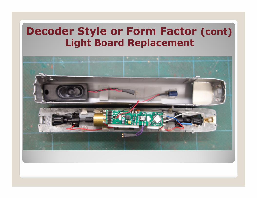
Decoder Style or Form Factor Decoder Style or Form Factor (cont)(cont)
Light Board ReplacementLight Board Replacement
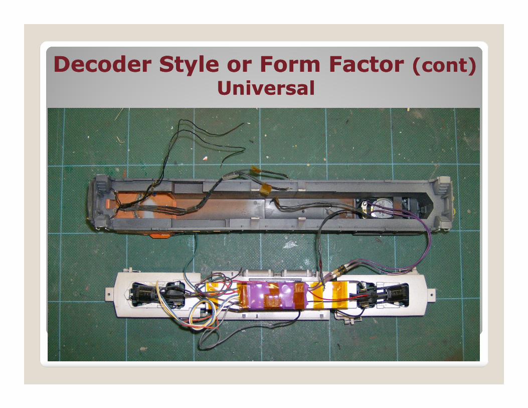
Decoder Style or Form FactorDecoder Style or Form Factor (cont)(cont)
Universal Decoder
More challenging in some ways
May require splicing wires
Have to tame wires
Most versatileMost versatile
Will work in most any engine situation
Made for non DCC ready engines
Good when lack of space is issue (more flexible decoder location)
Decoder Style or Form Factor Decoder Style or Form Factor (cont)(cont)
UniversalUniversal

Decoder Style or Form Factor Decoder Style or Form Factor (cont)(cont)
Plug InPlug In
Easiest to install
Uses existing light board
May not fit in some cases
You can add plug to any hard wired decoder, but all functions may not work
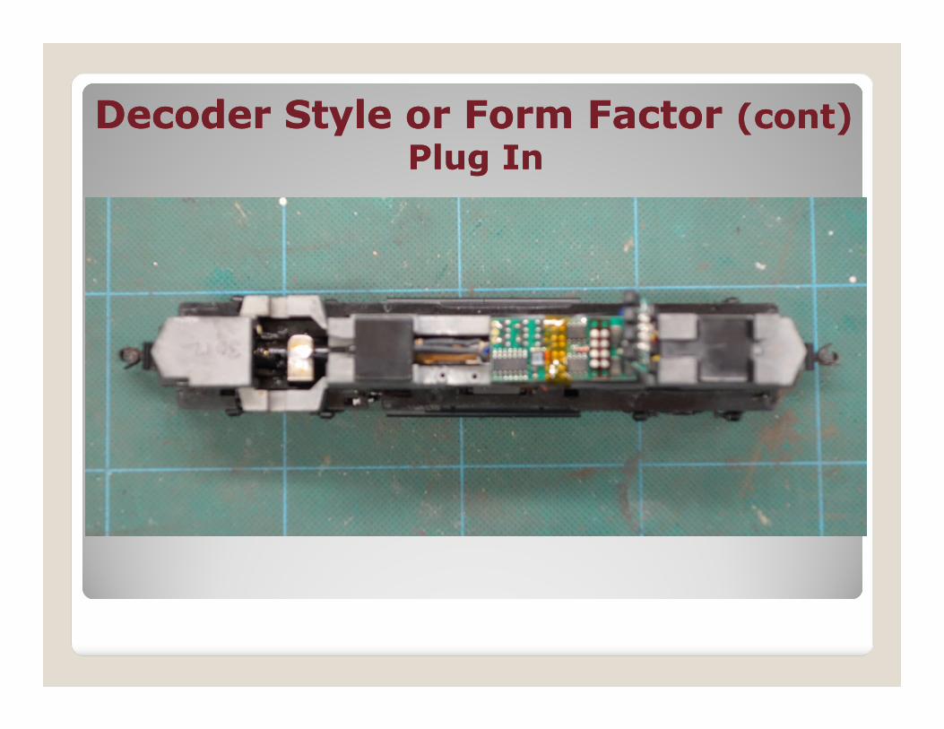
Decoder Style or Form Factor Decoder Style or Form Factor (cont)(cont)
Plug InPlug In

Typical DecodersTypical Decoders
TSU 1000 TSU 1000 Sound NCE D13SRP (1.3 – 2.0 amp)
TSU AT1000 Sound TCS T1 (1.3 – 2.0 amp)

Typical Decoders (cont)Typical Decoders (cont)
NCE SW9-SR NCE D15-SRP
NCE DA-SR NCE N12SR

Tools NeededTools Needed
Small soldering iron - 25 watt preferred
Needle nose pliers
Wire cutter and striper
X-Acto knife, small screwdrivers, etc. X-Acto knife, small screwdrivers, etc.
Volt/Ohm meter
Engine cradle
“Helping Hands” (optional, but useful)

Some Useful SuppliesSome Useful Supplies Small diameter rosin core solder Small diameter shrink tubing Kapton or electrical tape (with reservations)
Other Styrene and 3M™ foam mounting tape Styrene and 3M™ foam mounting tape Flexible wire in 24-32 ga. in suitable colors Aliene’s Tacky Glue Tacky Putty Dental Floss Sub miniature plugs LEDs, Assorted resistors, etc.
Engine PreparationEngine Preparation
Test run on DC to make sure it runs properly It will not run better on DCC
Check Stall Current at Max Voltage Remove couplers and screws needed to remove shell
Place shell and loose parts aside Place shell and loose parts aside Is engine “DCC ready?” This term has different meanings. Sometimes engine has a plug other times it just means the motor brushes are insulated from the frame
Remove factory lighting board (If not needed)
Check motor to insure brushes are isolated from the frame and trucks.

Determine decoder mounting method Plug in decoder Light board replacement (often engine specific) but can be adapted… Universal decoder“Plug in” decoder
Decoder SelectionDecoder Selection
“Plug in” decoder Should have 8 or 9 pin plug Need to match decoder and engine plugs
No soldering requiredUse existing lighting
Installation PreparationInstallation Preparation
Does the engine have bulbs or LEDs
Does the decoder have the proper output for selected lights bulbs/LEDs?
If the decoder is not ready for LEDs prepare them by adding a suitable resistor (470Ω to 2KΩ+ usually work). Increasing the value will decrease the light brightness.

Installation Preparation(cont) Installation Preparation(cont)
Remove light board (if not needed)
Identify wires (not all manufacturers follow the NMRA standard)
Check that motor brushes are insulated from framefrom frame
Install selected lighting in shell
Select resistor if needed
Small ¼ watt resistor is all that is usually needed

Typical Decoder WiringTypical Decoder Wiring
Red
Black
WARNING: To prevent decoder damage:
always make sure the motor brushes are
properly isolated before applying power.DC Motor
Right Rail
Left Rail
White
Gray
OrangeMotor –
Motor +
Right Track Power
Left Track Power
flatF0F
“Sunny White” LEDs are
used instead of the
incandescent lamps with
the 1,000 ohm resistor
for each. Resistor can
also be “wired” into each
function wire.
White
Blue
DCC decoder
Output 1 (F0)
Light Common
Output 2 (F0)
Output 3 (F1)
flat
flat
flat
F0F
Front Headlight
F0R
Rear Headlight
F1 Function
Note: The Blue function common wire is
positive rectified approx 12 volts DC
Note 2: The function wire provides a
ground when the function is operated.
DCC cecoder wiring connections showing voltage dropping resistors in the common wire.

Selected DecoderSelected Decoder
Used with permission, NCE Corp.
Most manufacturers have decoder application or selection notes on their web site
Often they have photos of specific installations


InstallationInstallation
ConclusionConclusion
Plan ahead for more professional installation
Take your time for a reliable installation
Many models are similar and you can use similar techniquessimilar techniques
Not bound to one “traditional” method
Start simple and work up


