Download - damage tolerance assessment branch

National Aeronautics and Space Administration
dam
age
tole
ranc
e as
sess
men
t bra
nch
Marshall Space Flight Center

Fracture Test of Solid Motor Inert Propellant
Infrared Thermography of the External Tank Nosecone
Eddy Current Testing of a hole
Close-up of 45° crack with Von Mises stress map display and 100× exaggerated deformation.

1
EM20 Damage Tolerance Assessment BranchThe Damage Tolerance Assessment Branch evalu-ates the ability of a structure to perform reliably throughout its service life in the presence of a defect, crack, or other form of damage. Such assessment is fundamental to the use of structural materials and requires an integral blend of materials engineering, fracture testing and analysis, and nondestructive evaluation. The vision of the Branch is to increase the safety of manned space flight by improving the fracture control and the associated nondestructive evaluation processes through development and application of standards, guidelines, advanced test and analytical methods.
The Branch also strives to assist and solve non-aero-space related NDE and damage tolerance problems, providing consultation, prototyping and inspection services.
Damage Tolerance Assessment Branch ContactsDr. Wayne R. Gamwell, Branch [email protected], 256–544–2592
Mr. Mike Suits, Deputy Branch [email protected], 256–544–8336
2
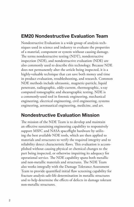
EM20 Nondestructive Evaluation TeamNondestructive Evaluation is a wide group of analysis tech-niques used in science and industry to evaluate the properties of a material, component or system without causing damage. The terms nondestructive testing (NDT), nondestructive inspection (NDI), and nondestructive evaluation (NDE) are also commonly used to describe this technology. Because NDE does not permanently alter the article being inspected, it is a highly-valuable technique that can save both money and time in product evaluation, troubleshooting, and research. Common NDE methods include ultrasonic, magnetic-particle, liquid penetrant, radiographic, eddy-current, thermographic, x-ray computed tomographic and shearographic testing. NDE is a commonly-used tool in forensic engineering, mechanical engineering, electrical engineering, civil engineering, systems engineering, aeronautical engineering, medicine, and art.
Nondestructive Evaluation Mission The mission of the NDE Team is to develop and maintain an effective sustaining engineering capability to responsively support MSFC and NASA spaceflight hardware by utiliz-ing the best available NDE tools, which are then applied to materials and structures to verify the required integrity and to reliability detect characteristic flaws. This evaluation is accom-plished without causing physical or chemical changes to the part being inspected, or otherwise impairing its adequacy for operational service. The NDE capability spans both metallic and non-metallic materials and structures. The NDE Team also works integrally with the Damage Tolerance Assessment Team to provide quantified initial flaw screening capability for fracture analysis safe-life determination in metallic structures and to help determine the effects of defects in damage tolerant non-metallic structures.

3
Recent Activities• Developmentofon-padradiographictechniques
for detection and evaluation of cracked 2090 aluminum stringers on the Space Shuttle External Tank (ET).
• DevelopmentofNDEforlocatingdefectsinthespray-on-foam-insulation of the Space Shuttle ET.
• Developmentofeddycurrenttestingtechniquesfor Space Shuttle Main Engine Flow Liners
• Developmentofthermographictestingtechniquesfor cold wall leak detection of the Space Shuttle Main Engine.
• Development of phased array ultrasonic testing for friction stir welding and friction stir plug welding.
Phased Array Ultrasonic Testing of a Common Bulkhead.

4
PH
YSICS
ENER
GY
INPUT NDE METHOD RESPONSE/OUTPUT ACTION NEWTON’S 3RD LAW REACTION
MEC
HA
NIC
AL
ELECTR
ICA
L M
AG
NETIC
LO
AD
ELECTR
OM
AG
NETIC
CAPILLARY PRESSURE
Laser Ultrasonics (Laser UT)
Terahertz (THz)
Microwave/Millimeter Wave (MMW)
Penetrant (PT)
Magnetic Particle (MT)
Eddy Current (ET)
Electromagnetic Acoustial Transducer
Electrical Potential Drop (da dN)
Computed Tomography (CT)
Backscatter X-Ray
Radiographic (RT)
Shearography (SH)
Ultrasonics (UT)/Phased Array UT
Mechanical Impedance Analysis (MIA)
MEASURED ULTRASOUND
FIELD IMPEDANCE CHANGE
LEAKAGE FIELD
SPECTRUM
INDUCTION
IMAGE
VISUA
L
Visible
HEAT
ATMOSPHERIC Acoustic Emission (AE)
COMPRESSION/ TENSION
Thermography (IRT)
SOUND
LIGHT
VISIBLE BLEEDOUT
MEASURED ULTRASOUND
RESONANCE
TEMPERATURE
VOLTAGE CHANGE
LIGHT
SURFACE DISPLACMENT
DIELECTRIC DIFFERENCES
DIELECTRIC DIFFERENCES
DENSITY PHOTON COUNT
DENSITY PHOTON COUNT
LATENT FILM DENSITY

5
Nondestructive Evaluation Methods Development at Marshall• Evaluatethestructuralintegrityofobjects,materials,and
systems for internal and external defects without impairing its future usefulness.
•TheNDEteamworksproblemsfromtechniquedevelopmentto demonstration to implementation and finally integration with production tooling and process flow.
The MSFC NDE team includes the following endeavors:• Compositematerialsscreeningandadvancedsingleand
multi-layer bondline interrogation.• SupportsadvancedFrictionStirWelddevelopment,provid-
ing process verification.• Supportsmechanicalpropertiesallowablestesting.• SupportsAgency-wideworkinggroupsinNDEincludingthe
NASA NDE Working Group (NNWG), the NASA Engineer-ing Safety Center (NESC) NDE Technical Discipline Team, the Chief Engineer’s NDE Technical Specialist Team and
the NASA standards office for NDE requirements documents.•Supportsthedevelopment
and qualification of test articles to provide clear and rational NDE and proof logic.
•Developslargescaleauto-mated NDE processes.
•Developsverification,validation and certification programs for advanced NDE methods by proper inspector training and validated probability of detection studies.
• ActiveAmericanSocietyofNondestructiveTesting(ASNT)Certifications in all conventional methods as well as in-house NAS-410 certification of inspectors.
Microwave/Millimeter Wave Testing

6
At Marshall the Nondestructive Evaluation Team provides:•Theinnovativeapplicationof
conventional and advanced NDE methods and processes to manned and unmanned space flight systems, components and materials.
•LeadershipinthedevelopmentofNASA NDE Standards and NDE Requirements for manned flight systems.
•Consultationandexpertiseforanomaly investigations in support of manned flight systems.
•ActivemembershipontheMSFCFractureControl Board.
• OneofthemostadvancedmicrowaveNDElaboratories in the world.
• Portablereal-timeradiographyfordynamicmotortest environments.
• ConventionalNDEservicesutilizingstate-of-the-art ultrasound, radiography, eddy current fluorescent dye penetrant, magnetic particle, thickness measurement, bond testing, and borescopic (visual) systems.
• AdvancedNDEservicessuchasTerahertzimaging, thermography, backscatter x-ray, laser ultrasound, laser shearography, high-resolution/high energy computed tomography.
•Thedesignandvalidationofcapabilitystudies for new NDE applications.
•ThedesignandfabricationofrealisticNDE reliability and calibration standards.
Computed Tomography Testing

7
NDE Spin-offsThefollowingarejustafewofthenon-aerospacerelated tasks that the MSFC NDE team has worked:•Thermographyofaircraftbrakedisks.• Ultrasonicleakdetectionofdieselenginecompo-
nents.• Radiographytestingofpackageslookingfor
explosives.• EddyCurrentandpentranttestingofaircraft
parts.• EddycurrentofboltsholdingSaturnVtoits
display fixture.• Ultrasonictestingofhelicopterswashplatesand
rotor components.• Computedtomographyofacartires/parts,logs,
time capsule, fossils.• UltrasonictestingonbondlinesinDepartmentof
Defense Missiles.• Lasershearographyandultrasonictestingon
graphite golf shafts.
Nondestructive Evaluation Team ContactMr. James Walker, Team [email protected],256–961–1784

8
EM20 Damage Tolerance TeamDamage Tolerance is a property of a structure relating to its ability to sustain defects safely until repair can be affected to meet usage requirements. The approach to engineering design to account for damage tolerance is based on the assumption that flaws can exist in any structure and such flaws sometimes propagate with usage. This approach is commonly used in aerospace engineering to manage the extension of cracks in structures through the application of the principles of fracture mechanics. A structure is considered to be damage tolerant if a maintenance program has been implemented that will result in the detection and repair of manu-facturing defects, accidental damage, and fatigue cracking before such damage reduces the residual strength of the structure below an acceptable limit, or if the structure can meet service life requirements in the presence of a defect without repair.
Damage Tolerance MissionThe mission of the Damage Tolerance Team is to develop and maintain an effective sustaining engineering capability to responsively support MSFC and NASA spaceflight hardware by utiliz-ing the best available fracture assessment tools and theories for thorough, accurate, and decisive solutions to engineering problems. The Team also pursues further development of engineering capabil-ity in damage tolerance testing and analysis to be implemented in assessment of issues facing MSFC and NASA programs.
9
Recent Activities• Failure analysis and test evaluation for debris liberation estimatessupportingShuttleMainPropulsionSystemvalve fracture.
• Material test data evaluation supporting Shuttle External Tank Stiffener Rib fracture.
• Computation of acceptable disbond sizes for a cryogenic tank common bulkhead honeycomb sandwich structure.
• Determination of the critical defect location in a fric-tion stir plug weld configuration for a propellant tank structure.
• Understandingofimpactdamageinfluenceonthedesign of an interstage honeycomb thrust structure.
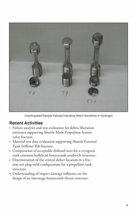
Unanticipated Sample Failures Indicating Notch Sensitivity in Hydrogen

10
Damage Tolerance/Fracture Control and Analysis at Marshall•Materialcharacterizationplanning,dataevaluation,and
generation of design curves for metallic fracture and composites damage tolerance data.
• Analyticalpredictionsinfracturemechanicsformetallichardware and residual strength for composite hardware.
• Componenttestobjectivesfordamageevaluationandproof test.
• Fracturecontrolanddamagetoleranceguidanceformitigation of failure due to defects or damage.
Finite Element Predictions for a Pressure Vessel Nozzle Interface
Finite Element Analysis of Mode III Fracture

11
The MSFC Damage Tolerance Team provides:• Customizedexperimentaltechniquesdevelopedtoassess
toughness and fatigue crack growth in metallic materials, as well as damage tolerance of structures or components under unique loads and environments.
• Developmentofmethodologiesforexperimentallyassess-ing damage tolerance of solid composite laminates and honeycomb cored composite structures.
• Advancedanalysisoffractureandfatigueinmetallicstructures using finite element and boundary element techniques.
• Structuralassessmentinaccordancewithallcommoncodesandcriteria(e.g.,NASGRO®,API,orR6failureassessment diagrams, constraint-corrected JIc, etc.)
• Specializedfractureanalysisforshort-life,high-stresscomponents commonly found in launch vehicle applica-tions.
• Developmentofadvancedanalysissoftwareandtechniques applicable to launch vehicle structures and materials.
• Consultationonfracturecontrolimplementationfornew and advanced programs at MSFC and throughout NASA.
• ChairmanshipandtechnicalsupportfortheMSFCFracture Control Board.
• DevelopmentandrefinementofNASAandindustryguidelines and standards.
• Emphasisoninnovativeapproachestotheimplementa-tion of fracture control for advanced materials and structures.
• SupporttotheNASAEngineeringandSafetyCenter(NESC).

12
Failed Compression-After-Impact Specimen

13
Damage Tolerance Spin-offsThe following represent a few of the activities pursued to advance engineering capability in damage tolerance assessment:• Supportfordevelopmentoffiniteelement
modules for integration with FEA Crack Software.
• SupportfordevelopmentofintegrationbetweentheNASGRO® and FASTRAN Analysis Codes.
• Supportforinvestigationsintodelaminationeffects in Aluminum-Lithium alloys.
• Supportforinvestigationsintoboundaryelementand finite element integrated crack turning predictions.
Damage Tolerance Team ContactMr. Wayne Gregg, Team [email protected], 256–544–5501

14
National Aeronautics and Space Administration
George C. Marshall Space Flight CenterHuntsville, AL 35812www.nasa.gov/marshall
www.nasa.gov
NP-2012-08-91-MSFC8–541009


