
Jordan Journal of Civil Engineering, Volume 13, No. 4, 2019
- 538 - © 2019 JUST. All Rights Reserved.
Damage Characterization in Building Structures Due to Blast Actions
B. Ahmed 1)*, F. Dinu 2) and I. Marginean 2)
1) Centre for Infrastructure Engineering, Western Sydney University, Sydney, Australia. 2) Department of Steel Structures and Structural Mechanics, Politehnica University Timisoara, Romania.
* Corresponding Author. E-Mail: B. [email protected]
ABSTRACT
Structural identification is a technique that can be used to assess/characterize the damage state through the
variation in eigenfrequencies, damping ratios and modal shapes in a structure or element. It has recently
received more attention for the practical implementation in several fields, including damage assessment for
structures following blast or explosion events. At present, large infrastructure components, like civil
engineering structures, are the most convenient issue of consideration for structural identification. Structures
can be moderately or severely deteriorated due to accidental or intentional blasts or explosions. Structural
engineers and other stakeholders, like rescue and emergency agencies, are more concerned about the design of
structures, design life span, proper maintenance, repair and residual capacity of structural systems in many
countries. This research work focuses on the experimental and analytical modal analysis of a full-scale steel
frame structure building aiming to develop coherent scenarios that combine the probability of the hazard event
with the structural vulnerability in case of a close-in detonation. Field tests were carried out by forced vibration
testing under hammer excitations. First, a series of tests were conducted for the undamaged structure using
classical experimental modal analysis. Then, in order to model a structural damage, a secondary beam was
dismantled (thus a damage was created artificially) and the measurements were repeated. The change in
structural behaviour was observed by identifying the changes in the stiffness and natural frequencies of the
structure. The modal parameters measured from field tests were then used to validate finite element models
using SAP2000 program. They were corrected, so that the numerical natural frequencies and mode shapes
match the experimental data. Good agreement was found in identifying the frequencies for the three-
dimensional finite element models for both damaged and undamaged structures. Then, using the calibrated
numerical model, several blast- induced damages were used in a numerical study. For the internal damage or
non-visible crack, four different damage scenarios were made by the FE model for internal and external blast
actions. The modal parameters changed significantly for higher modes for higher reduction of stiffness at the
column-beam and base connections. The results (experimental data, calibrated numerical model) can be used
as reference values of the undamaged structure for further investigations after blast tests.
KEYWORDS: SHM, Modal parameters, FEM modelling, Damage characterization, EMA.
INTRODUCTION
Structural identification is getting more importance
through finite element model updating and experimental
modal analysis technique to assess dynamic properties,
as well as structural health and performance monitoring
(Timothy Kernicky et al., 2017). Structural
identification basically uses performance-based civil
engineering modeling that is performed by
field/experimental measurements and the validation is
done by using numerical models. In the study, SAP2000 Received on 2/7/2019. Accepted for Publication on 13/10/2019.
Jordan Journal of Civil Engineering, Volume 13, No. 4, 2019
- 539 -
program was used for calibration of the experimental
data obtained using Bruel and Kjaer vibration
measurement technology and equipment. Structural
design validation, practical quality control of
construction, performance for retrofitting and
rehabilitation effectiveness, damage detection and
lifecycle analysis for long-term performance and
structural health and performance monitoring (Çatbaş et
al., 2013) are promising issues for structural
identification and characterization (Timothy Kernicky et
al., 2017). Structural identification studies for large civil
engineering structures, like long-span bridges, high-rise
buildings, wind turbines, offshore structures and towers,
are subjected to undesired and/or unexpected hazards. In
case of blast action, structural deterioration of the frame
building, structural responses for pre-blast and post-
blast conditions are conducted by blast overpressure
transducers and shock accelerometers. Performance-
based (Aktan, A. et al., 2013) analysis for civil
engineering structure and health monitoring has some
key challenges for structural identification because of
uncertainties of parameter estimation and the necessity
of finding alternative better solutions for physical
properties of the structures. The main goal of model
updating is to find the solution to get the best possible
match of stiffness and mass matrices of an analytical
model of the structure to the experimentally measured
values (Timothy Kernicky et al., 2017). Two important
methods: deterministic and probabilistic, are used for
finite element model updating. The uncertainty
parameters of the model can be assessed by
deterministic methods for structural identification of
several full-scale structures (Bakir et al., 2008; Deng, L.
et al., 2009; Marwala, T., 2010). Modal parameter
estimation is performed through system identification
using both deterministic and stochastic Subspace
Identification (SSI) system algorithms. Structural
identification for the existing structures is an auspicious
solution for decision-making to minimize unnecessary
cost for repairing, retrofitting and replacement (Romain
Pasquier et al., 2016). Unexpected errors of modeling
can be minimized for the existing civil engineering
structures by a structural identification process based on
residual minimization approaches (Yarnold et al., 2015;
Fontan et al., 2014; Baroth et al., 2010; Schlune et al.,
2009). Physical properties and structural conditions
from the identification results are observed by the
diagnostic process. Higher number of sensors is required
for computing structural identification for diagnosis and
prognosis of existing structures.
The response of the structures under reacting forces
defines the structural behavior that is urging to analyze.
External forces can be introduced in different ways and
characterize the dynamic properties (modes and natural
resonant frequencies). Modal parameters are important,
because they describe the inherent dynamic properties
of a structure. The set of modal parameters constitutes a
unique set of numbers that can be used for model
correlation and updating, design verification,
benchmarking, troubleshooting, quality control or
structural health monitoring. The structure is excited
with a hammer or shaker and its response is measured
with accelerometers. Techniques, like operational modal
analysis (OMA) and operating deflection shape analysis
(ODS), work while the structure is in operation,
allowing to get a realistic picture without having to
artificially excite the structure (Bruel and Kjaer module:
Type 7765, 7765‐A, 7765‐B and 8761).
The three important modal parameters of natural
frequencies, damping ratios and mode shapes have
become a major concern for representing structural
dynamics. Many researchers did a lot of work related to
modal parameter estimation for describing the dynamic
behavior of structures.
R. Cantieni (2004) conducted a very valuable
research on experimental methods used in system
identification of civil engineering structures, like
buildings, bridges, dams, wind turbines, towers and road
networks that are vibrated due to dynamic forces.
Brownjohn et al. (2010) examined the dynamic behavior
of Humber bridge based on operational modal analysis
in ambient conditions. Ahmet Can Altunışık et al.
(2017) experimented the structural identification of a
cantilever beam with multiple cracks by three different

Damage Characterization in Building… B. Ahmed, F. Dinu and I. Marginean
- 540 -
operational methods (EFDD, CFDD and SSI) and the
modal parameters were verified by finite element tool
ANSYS. J. B. Hansen et al. (2017) proposed “a new
scenario-based approach to damage detection using
operational modal parameter estimates”. He did
vibration-based damage introduction and identification
by the modal parameters. Structural health monitoring
(SHM) of structures was measured by the damage
detection techniques of four important factors:
detection, localization, quantification and prognosis (A.
Rytter, 1993). Mustapha Dahak et al. (2017) measured
the physical properties of cantilever beam and made it
flexible to reduce natural frequencies. Damages were
introduced in the different zones on the cantilever beam,
while experimental investigation was done for
measuring the modal parameters and ANSYS software
was used for the verification of the experimental results.
MAC value can correlate the modal shapes of the
damaged and undamaged structures (W. M. West,
1984). J. Zhang et al. (2013) presented structural
identification for long-span bridge by three separate
post-processing experimental methods: Peak Picking,
PolyMAX and Complex mode indicator function.
Aktan, A. E. et al. (1997) identified structural
parameters by experimental analysis and calibrated
them by numerical models. Kijewski-Correa et al.
(2007) measured the dynamic parameters
experimentally and performed validation by finite
element tools. Conte J.P. et al. (2008) identified
normalized vibration mode shapes using MNExT-ERA
based on ambient vibration data (S = Symmetric; AS =
Anti-Symmetric; H, V and T = Horizontal, Vertical and
Torsional mode, respectively). Wei-Xin Ren et al.
(2004) conducted laboratory experimental testing to
measure the modal parameters of a steel arch bridge in
operating conditions. Álvaro Cunha et al. (2004) applied
output only modal identification methods to perform
modal parameter extraction for different types of civil
engineering structures. Brian J. Schwarz et al. (1999)
conducted “experimental modal analysis” for measuring
the FRF (modal parameters) by using the FFT analyzer
and a set of FFT curve fitting. Ibsen et al. (2006)
represented on “experimental modal analysis” for wind
turbine and estimation of modal parameters by using
ambient response testing and modal identification
(ARTeMIS). Dongming Feng et al. (2017) introduced an
advanced technique to monitor the structural health in a
cost-effective way. Advanced noncontact vision-based
systems offer a promising alternative of conventional
experimental methods. M. Molinari et al. (2009)
represented on “damage identification of a 3D full-scale
steel–concrete composite structure with partial-strength
joints at different pseudo-dynamic load levels” and
highlighted system identification methods for damage
detection, localization and quantification by measuring
actual modal parameters of a structure. Ruqiang Yan et
al. (2015) discussed the structural health monitoring of
a spindle by stochastic subspace identification (SSI),
using Peeters B. et al. (1999) experimental methods in
operating conditions. M. Hassan Haeri et al. (2017)
introduced an innovative method; namely, inverse
vibration technique, for offshore jacket platforms. Jia He
et al. (2017) applied two sets of investigation: MR
dampers were employed for vibration control and the
EKF-based approach was used for damage detection for
Kobe earthquake and Northridge earthquake. G. Acunzo
et al. (2017) proposed a new method, Multi Rigid
Polygons (MRP) model, for building modal estimations.
E. Peter Carden et al. (2008) examined structural health
monitoring (SHM) for a civil engineering structure,
which was done by Autoregressive Moving Average
(ARMA) model to detect and locate damage. T. H.
Ooijevaar et al. (2010) developed damage detection
methods applied experimentally for a carbon fiber
PEKK-reinforced composite T-beam. S. Nagarajaiah et
al. (2009) introduced a new technique for modal
parameter estimation. He applied output-only modal
identification for structural damage detection.
Research Objectives and Scope
Experimental validation is the most reliable way to
demonstrate the performance of a building structural
system. However, there are still some uncertainties
about the expected performance of the building system

Jordan Journal of Civil Engineering, Volume 13, No. 4, 2019
- 541 -
when subjected to blast load because of the many
variables included in the process. The application of
structural identification for full-scale laboratory testing
of a steel frame building subjected to blast allows a
better understanding of blast effects, including the post-
blast condition and residual capacity of the building
structure. The research mainly focused on the
assessment of dynamic properties of a full-scale steel
frame building model and some preliminary evaluations
regarding the structural vulnerability in case of a close-
in detonation.
Application of St-Id in Structural Engineering
The development of the society and the need for
more advanced, more economical and longer lifetime of
buildings and infrastructures, like tall buildings, dams,
large cable stayed or suspension bridges, towers, wind
turbines, aircraft structures or other special structures,
require adequate methods and tools to allow for accurate
structural identification of the most relevant static and
dynamic properties. Numerical modelling, although it is
a powerful tool that witnessed important developments
in the past decades, requires the validation of the results
through analytical and/or experimental means.
A lot of research work had been done in the past to
identify the dynamic characteristics of civil engineering
structures. Some applications of Bruel and Kjaer
experimental modal analysis (EMA) for estimation of
modal parameters for different structures are presented
in Figures 1-5. Many researchers have conducted
experimental modal analysis and analytical modal
analysis for long-span bridges, tall buildings, traffic
roads, towers, wind turbines,… and so on. A lot of
research related to structural identification and structural
health monitoring has been done by different researchers
based on experimental modal analysis for civil
engineering structures.
Figure (1): Modal parameter estimation for wind turbine (Bruel and Kjaer manual: type 8760)

Damage Characterization in Building… B. Ahmed, F. Dinu and I. Marginean
- 542 -
Figure (2): Modal parameter estimation for bridge (Abdurrahman Sahin et al., 2016)
Figure (3): Modal parameter estimation for a beam structure (Bruel and Kjaer manual: access code: 636 832 431, 2017)

Jordan Journal of Civil Engineering, Volume 13, No. 4, 2019
- 543 -
Figure (4): Modal parameter estimation for air craft (Bruel and Kjaer manual: Type 8761)
Figure (5): Different physical mode shapes by experimental modal analysis (Peter, 2017)

Damage Characterization in Building… B. Ahmed, F. Dinu and I. Marginean
- 544 -
Damage Detection by Experimental Modal Analysis
Structural health monitoring after long-term
operation is the key source to detect damage. Time-to-
time health monitoring indicates physical changes of
structures, which helps identify damage occurrence,
location of damage and severity of damage. Mainly,
damage indicators are the key parameters as input and
they are unified to a single control value with a
corresponding statistical threshold. This threshold acts
as a control chart for identifying damage automatically
when the threshold is being passed after an analysis. As
example, a bridge is taken (Figure 6) for detecting
damage after long-term service of that bridge, where
eight reference measurements representing the
undamaged state were performed. Eight measurements
were recorded for the undamaged bridge and other 14
measurements were taken after introducing damage. The
first six measurements out of the eight measurements
were used as a baseline (reference) model determined by
the module. The threshold is automatically estimated
based on statistical evaluation of the damage indices of
the six reference measurements. The last two reference
measurements remain below the reference threshold
(green bars). This means that the bridge is still
serviceable or undamaged. The last 14 measurements
that were recorded after damage introduced all pass the
threshold significantly and indicate a permanent damage
(red bars). Mode tracking was done as well. The lower
left display indicates that the first two modes are
basically unaffected by the damage, whereas the natural
frequency for the highest mode changes, disappears
completely during the first set of damage measurements
and reappears again later. Tracking of the third mode is
impossible after damage is introduced (Bruel and Kjaer
product document: OMA Pro BZ-8553).
Figure (6): Damage detection of bridge by operational modal analysis
(Bruel and Kjaer manual: Type 8760-8762; OMA Pro BZ: 8553)
Jordan Journal of Civil Engineering, Volume 13, No. 4, 2019
- 545 -
Building Frames under Blast Action
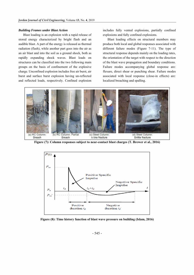
Blast loading is an explosion with a rapid release of
stored energy characterized by bright flash and an
audible blast. A part of the energy is released as thermal
radiation (flash), while another part goes into the air as
an air blast and into the soil as a ground shock, both as
rapidly expanding shock waves. Blast loads on
structures can be classified into the two following main
groups on the basis of confinement of the explosive
charge. Unconfined explosion includes free air burst, air
burst and surface burst explosion having un-reflected
and reflected loads, respectively. Confined explosion
includes fully vented explosions, partially confined
explosions and fully confined explosions.
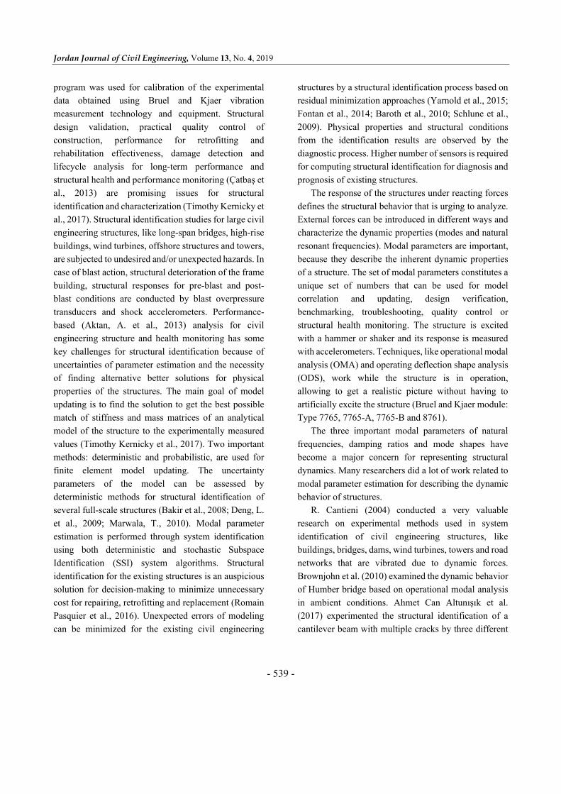
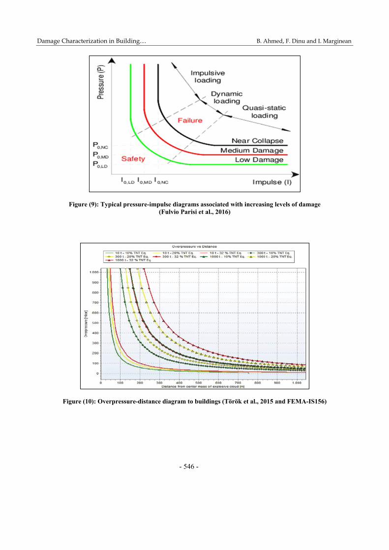
Blast loading effects on structural members may
produce both local and global responses associated with
different failure modes (Figure 7-11). The type of
structural response depends mainly on the loading rates,
the orientation of the target with respect to the direction
of the blast wave propagation and boundary conditions.
Failure modes accompanying global response are:
flexure, direct shear or punching shear. Failure modes
associated with local response (close-in effects) are:
localized breaching and spalling.
Figure (7): Column responses subject to near-contact blast charges (T. Brewer et al., 2016)
Figure (8): Time history function of blast wave pressure on building (Islam, 2016)
Damage Characterization in Building… B. Ahmed, F. Dinu and I. Marginean
- 546 -
Figure (9): Typical pressure-impulse diagrams associated with increasing levels of damage (Fulvio Parisi et al., 2016)
Figure (10): Overpressure-distance diagram to buildings (Török et al., 2015 and FEMA-IS156)

Jordan Journal of Civil Engineering, Volume 13, No. 4, 2019
- 547 -
Figure (11): Standoff distance-explosion weight diagram to buildings (Török et al., 2015)
Research Methodology
Description of Frame Building Model
The full-scale building model is a two-span, two-bay
and two-story steel structure (Figure 12). The bays and
spans measure 4.50 m and 3.0 m, respectively, while
each story is 2.5 m high. The structural system is made
of moment-resisting frames in the transversal direction,
while in the longitudinal direction it is made of
concentrically braced frames placed on perimeter
frames. The extended end-plate bolted beam-to-column
connections in the moment-resisting frames are
designed as fully rigid and fully restrained connections.
Secondary beam-to-column connections and secondary
beam-to primary beam connections are pinned
connections. Columns are rigid at the base. The design
of the structure for permanent and seismic (low
seismicity, 0.10 g horizontal acceleration) design
conditions resulted in an IPE 270 section for main
beams; IPE 200 section for main secondary beams; and
secondary beams between frames were of IPE 160
section, while columns were of HEB 260 section. Note
that structural steel S275 (yield strength of 275N/mm2)
was used for beams and columns (Dinu et al., 2017-
2018).
Instrumentation and Vibration Measurements on
Initial (Undamaged) Structure
The experimental test for full-scale building in
Petrosani was done in two distinct phases. First step is
to fix each component of the instrument. Bruel and Kjaer
experiment consists of many important tools for
measuring vibrations. Accelerometer, impact hammer,
force transducer, laptop and connecting cables are the
most important parts of the total set of instruments.
Transducer and laptop are connected by the connecting
cables. The model of the building frame is drawn by the
numerical tool SAP2000. For experimental modal
analysis, geometry is needed. It can be drawn directly
there or can be exported from AUTO CAD file (str file;
uff), file formats and SAP2000 in dxf file format. The
model was exported from SAP2000 and imported to the
MTC hammer measurement software. The external
longitudinal frame and internal transverse frame were
selected for measuring the vibration. Corner column and
central column of the longitudinal frame were
considered for experimental testing. The location of the
best points to excite the structure was determined so as
to create almost equal levels of response in the several
modes of interest. A 3.20 lb black and hard hammer is

Damage Characterization in Building… B. Ahmed, F. Dinu and I. Marginean
- 548 -
attached at a distance of 0.625m, 1.25m and 1.875m
height from the bottom of the column carefully in plane
and out of plane. The positions where the average
response level is low will be better locations to attach
the accelerometers. Accelerometers are very sensitive. If
they are not fixed properly to the position of the structure
vibration, measurement data will not be accurate.
Accelerometers are fixed perfectly to the position of
measurement of the structure to make it a proper
connection with the member. For corner column,
longitudinal and transverse frame 1st accelerometer was
fixed at the base of the column. The next accelerometers
were positioned by keeping equal clear distance of
1.25m. The last accelerometer is positioned at the top
(5.0m from bottom) of the column. All accelerometers
are positioned in strong and weak axes for measuring
vibration in-plane and out of plane of the structural
frame. Two accelerometers are placed at the mid length
(2.25m from the end of beam) of the longitudinal beam
for out of plane measurement, but not for in-plane
measurement (Figure 13-15). No accelerometers were
fixed in the secondary beam. After positioning all
accelerometers, very sensitive cables were fixed in one
end of the accelerometers and the other end of the signal
processing device LAN-XI. The point number on the
frame and the channel number in the LAN-XI device
must be the same for best estimation of response signal.
Accelerometers, hammers and channel number are
reconfigured by MTC to make sure that all connections
are fixed properly.
Figure (12): Views and details of full-scale building frame: 3D view

Jordan Journal of Civil Engineering, Volume 13, No. 4, 2019
- 549 -
Figure (13): Positioning of accelerometers for
the longitudinal frame (in plane)
Figure (14): Positioning of accelerometers for
the longitudinal frame (out of plane)

Damage Characterization in Building… B. Ahmed, F. Dinu and I. Marginean
- 550 -
Figure (15): Positioning of accelerometers for the longitudinal frame (out of plane)
after removing secondary beam
Once the set-up is completed, the second step was to
perform experiments and measure the vibration of the
frame for excitation by the hammer. Measuring time,
frequency span, average number of readings, number of
hits for excitation, proper hits detection and property for
checking the frequency range are very essential to be set
before starting measurement. The total length of
measurement time is (6400/1000) 6.4 seconds and the
span of frequency for FFT was fixed as 1000Hz. Five
measurements were recorded for average. The more
number of measurements for average, the more accuracy
of the measurement.
Frequency domain method for measuring frequency
response H1 is used for exporting spectrum for
experimental modal analysis. Hammer weighing,
response weighing and hammer tip test were properly
performed during the measurement by uniform response
variation. After measurement, the initial mode shape can
be observed from MTC hammer test FRF validation
operation. The exact modal parameters are conducted by
pulse reflex experimental modal analysis for different
numbers of iterations and interpretations.
Experimental Results and Discussion
Modal Parameter Estimation for Longitudinal Frame
Column (in-Plane)
The results obtained from the Bruel and Kjaer
experimental modal analysis and finite element analysis
are matched with good agreement if there is a smaller
number of factors that affect the results. The factors of
uncertainties are mainly responsible for error in the
obtained results. In that case, additional
calibration/updating is needed for EMA and the model

Jordan Journal of Civil Engineering, Volume 13, No. 4, 2019
- 551 -
is updated by the numerical software. The finite element
numerical tools represent the best solution to corelate,
modify and update the modal parameters (mode shapes,
natural frequency and damping). Finite element
software SAP2000 was used for correlations and
updating of the experimental results. The natural
frequencies are determined from an eigenvalue analysis
of the 3D FEM and these results are compared with the
forced vibration data using the EMA post-processing
method. The vibrations of the structure were recorded
by means of 10 sensitive accelerometers and the
sensitivity of accelerometers was 1 V/g. A picture of the
test structure including position and orientation of the
accelerometers for longitudinal frame (in-plane) is
shown in Figure 13. The comparative presentation of
modal parameters for longitudinal frame (in-plane) is
illustrated in Table 1.
Table 1. Parameters (initial) from EMA and SAP2000 for longitudinal frame (in-plane)
Mode EMA SAP2000
Error (%)
Mode type Frequency (Hz) Damping (%)
Complexity (%)
Frequency (Hz)
1 12.54 1.22 0.00 14.06 10.81 Bending
2 51.42 1.36 0.00 51.55 0.25 Bending
3 126.37 0.32 0.00 120.81 -4.40 Bending
4 150.38 2.23 0.04 151.38 0.66 Bending
5 168.63 0.85 0.09 164.21 -2.62 Bending
6 192.17 2.78 0.03 194.79 -1.72 Bending
Table 2. Corrected modal parameters with respect to EMA and initial and calibrated SAP2000 model value for longitudinal frame (in-plane)
Mode Modal parameter estimation
Error (%)
Mode type EMA (Hz)
SAP2000 initial (Hz)
SAP2000 corrected (Hz)
Damping (%)
1 12.54 14.06 12.53 1.22 0.08 Bending2 51.42 51.55 50.35 1.36 2.08 Bending3 126.37 120.81 125.59 0.32 0.62 Bending4 150.38 151.38 150.04 2.23 0.23 Bending5 168.63 164.21 160.58 0.85 4.77 Bending6 192.17 190.79 188.39 2.78 1.97 Bending
Finite Element Model Calibration and Updating
The main aim of the finite element model updating
procedure is to correct the initial FEM values of the
selected parameters to minimize errors between
experimental result and numerical results. The main
steps to calibrate the model values are: i) development
of an initial vibration-based FEM model and identifying
the dynamic characteristics by experimental
measurement of the actual structure and ii) calibrating
and validating the vibration-based FEM model to suit
the objectives of the St-Id application. Hence, the
calibration step is one of the most important tasks of

Damage Characterization in Building… B. Ahmed, F. Dinu and I. Marginean
- 552 -
St-Id of a structure. In this study, the model is corrected
by modifying the stiffness at the beam-to-column
connections and column-base connections.
Comparison of frequencies before and after model
calibration is summarized in Table 2 and shows good
improvement in frequencies. Parametric study was then
introduced to find the optimum level of allowable
parameter change to improve the results of the updated
FE model. Here, the stiffness of connections was chosen
as the parameter for the parametric study. In the
parametric study, the stiffness of beam-to-column and
column-base connections was reduced by 53% and 32%,
respectively. Figure 16 illustrates the relationship
between error in frequency (against EMA frequency)
and the corrected FEM value. The table shows the EMA
frequencies and the FEM frequencies before and after
model calibration for the first six modes. From Table 2,
it can be seen that five out of six modes of the calibrated
FEM are in excellent match with the corresponding
EMA modes with only 0.08% or less error. The largest
error of 4.77% is with the fifth mode which still shows
a very good numerical-experimental correlation for
practical modelling purposes, especially when
considering the low frequency characteristics of this
particular mode as well as the scale of this building
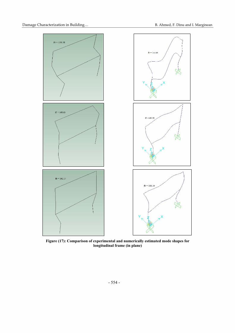
structure. Mode shapes are found after experimental
data interpretation and numerical model updating by
calibration for longitudinal frame in plane, as shown in
Figure 17.
Figure (16): Experimental measurement and numerical FEM corrected model value for longitudinal frame (in plane)
12.5
4 51.4
2
126.
37 150.
38
168.
63 192.
17
14.0
6 51.5
5
120.
81 151.
38
164.
21 194.
79
12.5
3 50.3
5
125.
59 150.
04
160.
58 188.
39
1 2 3 4 5 6
Fre
quen
cy (
HZ
)
Mode number
FREQUENCY FOR LONGITUDINALFRAME(IN PLANE)
EMA [fn (HZ)]SAP [fn (HZ)]SAP (corrected)[fn (HZ)]

Jordan Journal of Civil Engineering, Volume 13, No. 4, 2019
- 553 -
Damage Characterization in Building… B. Ahmed, F. Dinu and I. Marginean
- 554 -
Figure (17): Comparison of experimental and numerically estimated mode shapes for longitudinal frame (in plane)

Jordan Journal of Civil Engineering, Volume 13, No. 4, 2019
- 555 -
Figure (18): Frequency measured by EMA and SAP2000 for longitudinal frame (out of plane)
Modal Parameter Estimation for Longitudinal Frame
(out of Plane)
Modal parameter estimation was done by the same
procedure for longitudinal frame (out of plane) that was
used for the longitudinal frame (in-plane). 12
accelerometers and 6 reference hammers (DOF) are
fixed out of plane of the frame. The positioning and
orientation of the accelerometers and hammers for
longitudinal frame are shown Figure 14. Modal
parameters were measured by data interpretation for
longitudinal frame out of plane as shown in Figure 18.
Initial and calibrated estimated experimental and
numerical modal parameters for longitudinal frame (out
of plane) are presented in Table 3. Mode shapes are
found after experimental data interpretation and
numerical model updating by calibration for
longitudinal frame out of plane as illustrated in Figure
19.
Table 3. Corrected modal parameters with respect to EMA and initial and
calibrated SAP2000 model value for longitudinal frame (out of plane)
Mode Modal parameter estimation
Error (%)
Mode type EMA (Hz)
SAP2000 initial (Hz)
SAP2000 corrected (Hz)
Damping (%)
1 16.91 13.10 15.37 2.25 9.11 Bending2 75.48 74.75 74.77 0.07 0.94 Bending3 106.49 96.14 110.63 1.41 -3.89 Bending4 226.66 225.26 222.96 0.30 1.63 Bending5 277.29 276.68 275.12 0.27 0.78 Bending6 334.18 333.34 334.09 1.50 0.03 Bending
16.9
1 75.4
8
106.
49
226.
66 277.
29 334.
18
13.1
0 74.7
5
96.1
4
225.
26 276.
68 333.
34
15.3
7 74.7
7
110.
63
222.
96 275.
12 334.
09
1 2 3 4 5 6
Fre
quen
cy (
HZ
)
Mode number
FREQUENCY FOR LONGITUDINALFRAME(OUT OF PLANE)
EMA [fn (HZ)]SAP [fn (HZ)]SAP (corrected)[fn (HZ)]

Damage Characterization in Building… B. Ahmed, F. Dinu and I. Marginean
- 556 -

Jordan Journal of Civil Engineering, Volume 13, No. 4, 2019
- 557 -
Figure (19): Comparison of experimental and numerically estimated mode shapes for
longitudinal frame (out of plane)

Damage Characterization in Building… B. Ahmed, F. Dinu and I. Marginean
- 558 -
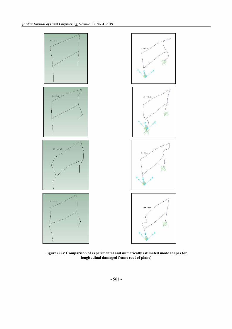
Modal Parameter Estimation for (Damaged)
Longitudinal Frame (out of Plane)
The physical properties (stability, stiffness, modal
mass,… etc.) of the frame changed for dismantled one
or more secondary beams. The secondary beam was
removed for observing the changes of modal parameters
as shown in Figure 20. Experimental modal parameters
were computed by the same procedure described for
longitudinal frame (out of plane). 11 accelerometers and
6 reference hammers (DOF) were fixed out of plane of
the frame. The positioning and orientation of the
accelerometers and hammers for longitudinal frame (out
of plane) are shown in Figure 15. Initial modal
parameters were measured by data interpretation for
longitudinal frame (out of plane) after secondary beam
dismantling. The modal parameters were corrected by
reducing the stiffness of base connections along both
axes after calibration as presented in Table 4. The table
shows the EMA frequencies and the FEM frequencies
before and after model calibration for the first six modes.
From Table 4, it can be seen that five out of six modes
of the calibrated FEM are in excellent match with the
corresponding EMA modes with only 0.04% or less
error. The largest error of 8.97% is with the 4th mode as
shown in Figure 21. Mode shapes are found after
experimental data interpretation and numerical model
updating by calibration for longitudinal frame out of
plane as illustrated in Figure 22.
Experimental Results and Discussions
The frequencies measured for undamaged and
damaged frames have significant changes for three
specific modes for longitudinal frame (out of plane). For
the 2nd mode, the frequency is 75.48 Hz for undamaged
condition and 75.75 Hz for damaged condition from
EMA. On the other hand, numerically, this value is
74.77Hz and 75.78 Hz for both conditions, respectively.
The mode calibration is good enough for EMA and
SAP2000 in mode 4 for damaged condition. The
frequency is 226.66Hz and 222.96 Hz for EMA and
SAP2000, respectively for longitudinal frame (out of
plane). But, for removing secondary beam, there is
significant difference in the frequency for undamaged
and damaged conditions. In undamaged condition, the
frequency is 226.66Hz, but it is 177.56Hz (Table 5) for
damaged condition in EMA. Numerically, there are also
big changes of frequency in the same mode. Frequency
is 222.96 Hz and 193.49 Hz for undamaged and
damaged conditions, respectively [Figure 23 and Figure
24]. Experimentally and numerically, the structural
properties changed significantly for the 6th mode. The
frame is more flexible because of low frequency
(334.18Hz and 277.30Hzs, respectively for both
conditions). Except for the 4th and 6th modes, all other
modes have no big differences of frequency for both
conditions in EMA and SAP2000. The 4th and 6th modes
are affected more due to physical property changes after
dismantling of secondary beam.
Table 4. Corrected modal parameters with respect to EMA and initial and calibrated SAP2000 model value for longitudinal damaged frame (out of plane)
Mode
Modal parameter estimation
Error (%) Mode type EMA (Hz)
SAP2000 initial (Hz)
SAP2000 corrected (Hz)
Damping (%)
1 19.49 24.99 18.79 1.10 3.59 Bending2 75.75 74.82 75.78 0.11 -0.04 Bending3 105.50 96.14 110.25 0.97 -4.50 Bending4 177.56 186.54 193.49 1.35 -8.97 Bending5 268.05 275.07 275.04 0.49 -2.61 Bending6 277.30 285.77 284.88 0.31 -2.73 Bending

Jordan Journal of Civil Engineering, Volume 13, No. 4, 2019
- 559 -
Table 5. Correlation of frequency for longitudinal frame (out of plane) for undamaged and damaged frame
Mode Measured
undamaged fn (Hz)
Calibrated model undamaged
fn (Hz)
Measured damaged
fn (Hz)
Calibrated model damaged
fn (Hz) Mode type
1 16.91 15.37 19.49 18.79 Bending
2 75.48 74.77 75.75 75.78 Bending
3 106.49 110.63 105.50 110.25 Bending
4 226.66 222.96 177.56 193.49 Bending
5 277.29 275.12 268.05 275.04 Bending
6 334.18 334.09 277.30 284.88 Bending
Figure (20): Dismantled secondary beam (red marked beam)

Damage Characterization in Building… B. Ahmed, F. Dinu and I. Marginean
- 560 -
Figure (21): Frequency measured by EMA and SAP2000 for
longitudinal damaged frame (out of plane)
19.4
9 75.7
5
105.
50
177.
56
268.
05
277.
30
24.9
9 74.8
2
96.1
4
186.
54
275.
07
285.
77
18.7
9 75.7
8 110.
25
193.
49
275.
04
284.
88
1 2 3 4 5 6
Fre
quen
cy (
HZ
)
Mode number
FREQUENCY FOR TRANSVERSE FRAME(OUT OF PLANE)-DAMAGED FRAME
EMA [fn (HZ)]SAP [fn (HZ)]SAP (corrected)[fn (HZ)]
Jordan Journal of Civil Engineering, Volume 13, No. 4, 2019
- 561 -
Figure (22): Comparison of experimental and numerically estimated mode shapes for
longitudinal damaged frame (out of plane)

Damage Characterization in Building… B. Ahmed, F. Dinu and I. Marginean
- 562 -
Figure (23): Frequency measured by EMA for longitudinal damaged frame (out of plane)
Figure (24): Frequency measured by SAP2000 for longitudinal damaged frame (out of plane)
16.9
1 75.4
8
106.
49
226.
66 277.
29 334.
18
19.4
9 75.7
5
105.
50
177.
56
268.
05
277.
30
1 2 3 4 5 6
Fre
quen
cy (
HZ
)
Mode number
FREQUENCY FROM EMALONGITUDINAL FRAME (OUT OF PLANE)
DamagedUndamaged
15.3
7 74.7
7 110.
63
222.
96 275.
12 334.
09
18.7
9 75.7
8
110.
25
193.
49
275.
04
284.
88
1 2 3 4 5 6
Fre
quen
cy (
HZ
)
Mode number
FREQUENCY FROM SAP2000LONGITUDINAL FRAME (OUT OF PLANE)
DamagedUndamaged

Jordan Journal of Civil Engineering, Volume 13, No. 4, 2019
- 563 -
a) b)
Figure (25): View of the structure with the position of the blast charge for external and internal blast tests
Figure (26): Relative frequency deviation between intact frame and damaged frame
-0.5
0.0
0.5
1.0
1.5
2.0
2.5
3.0
3.5
1 61
11
62
12
63
13
64
14
65
15
66
16
67
17
68
18
69
19
61
01
10
61
11
11
61
21
12
61
31
13
61
41
14
6Per
cent
age
freq
uenc
y de
viat
ion
Mode number
INTACT FRAME VS DAMAGE SCENERIO DC3-490% REDUCTION OF STIFFNESS AT BASE CONNECTION

Damage Characterization in Building… B. Ahmed, F. Dinu and I. Marginean
- 564 -
Figure (27): Relative frequency deviation between intact frames Blast Testing and Damage Prediction
The stiffness values at beam-to-column connection
and column-base connection of the intact frame are
32000 kNm/mrad and 1100000 kNm/mrad,
respectively. The building will be subjected to blasts
(TNT or equivalent) with different charges in sizes and
locations, resulting in different scaled distances. As the
scaled distance reduces, the peak overpressure
increases, thus causing the shear failure of the elements
located in the proximity. The potential for progressive
collapse following local damage will be also
investigated in the column and beam.
The column web will be affected by the external
charge (Figure 26 a) and the column flange and the
bottom flange of the primary beam are affected by the
internal blast (Figure 26 b). The effects of gravity load
on the columns and beams are not considered for blast
action during the test. Four different scenarios
depending on stiffness reduction at the column-base
connection for damage prediction are considered
subjected to external blast action.
Numerical Result for Damage Prediction and
Discussion
In this research, constructive implementation of
practical structural identification for full-scale building
steel structure is shown. The modal parameters have to be
updated in a convenient way by considering the finite
element model, geometry and material properties of
structural elements. The actual situations of the practical
structure can be analyzed by combining numerical
analysis and experimental investigation. The real strength
of FE model updating of a structure is confirmed. FE
model is the best tool to explain the essential physics of
the system of interest and it is capable of capturing and
simulating its critical physical behaviour.
Different damage predictions were considered for
calibrated numerical models and applied to preliminary
investigations on a full-scale building structure, using
different blast loading conditions. This prediction is
important, because it helps get a good idea about the non-
visible crack/damage due to loss of stiffness at connections
and building elements. Different damage scenarios were
considered for external and internal blast action.
-1.00.01.02.03.04.05.06.07.08.09.0
1 61
11
62
12
63
13
64
14
65
15
66
16
67
17
68
18
69
19
61
01
10
61
11
11
61
21
12
61
31
13
61
41
14
6Per
cent
age
freq
uenc
y de
viat
ion
Mode number
INTACT FRAME VS DAMAGE SCENERIO DBC3-490% REDUCTION OF STIFFNESS AT BEAM-COLUN AND
BASE CONNECTION

Jordan Journal of Civil Engineering, Volume 13, No. 4, 2019
- 565 -
Comparisons were made in terms of structural modal
parameters for each damage scenario. Due to blast
effects at the connections and other elements of the
structure, the dynamic properties depend on the
percentage reduction of stiffness at connections. From
the presented numerical result above, it can be
concluded that very few numbers of lower modes are
affected. But, for higher modes, significant changes in
the frequency exist for all damage scenarios. Damage
prediction at base connection when stiffness is reduced
simultaneously along the strong and weak axes is more
operative for some higher modes, see Figure 26. Most of
the higher modes are highly affected by internal blast
when reduced stiffness is applied simultaneously at the
external and internal column-beam connections and
base connections, see Figure 27.
Pulse Reflex Correlation Analysis
The correlation between experimental and numerical
eigenvalues and mode shapes is examined by pulse
reflex correlation analysis. There is an extensive
application of pulse reflex modal analysis to evaluate
different test and FEM strategies and to find out the
shortcomings in modal test and quality of FEM. The
mode shape, modal assurance criteria, auto-
orthogonality and paired modal data can be extracted
after correlation. It can clearly be indicated which mode
of FEM is corelated with the measured mode.
Experimental modal analysis is conducted for full-scale
steel building in the field to find the modal parameters
and to demonstrate the flexibility of the frame after
damage initiation. In this section, pulse reflex
correlation analysis is carried out to see the similarity of
the modal results for damaged and undamaged frames.
Damage location can be clearly extracted from the mode
shapes and eigenvalues.
Summary
Structural identification is used to illustrate the
damage state through the variation in eigenfrequencies,
damping ratios and modal shapes in a structure or
element. This research work focuses on the
experimental and analytical modal analysis of a full-
scale steel frame structure building aiming to develop
coherent scenarios that combine the probability of the
hazard event with the structural vulnerability in case of
a close-in detonation. The field tests were carried out by
forced vibration testing under hammer excitation. First
series of tests were conducted for the undamaged
structure using classical experimental modal analysis.
Then, in order to model a structural damage, a secondary
beam was dismantled and the measurements were
repeated. The change in structural behaviour was
observed by identifying the changes in the stiffness and
natural frequencies of the structure. The modal
parameters measured from field tests were then used to
validate finite element models using SAP2000 program.
Careful modelling of structural components was used in
mitigating uncertainty from the analytical point of view
and produced good correlation between the results
obtained from St-Id and the experiment. Significant
change was found in the frequency for damaged
initiations in longitudinal frame (out of plane) for both
EMA and numerical results. Experimentally and
numerically, the structural properties changed
significantly for the 6th mode. The frame is more flexible
because of low frequency (334.18Hz and 277.30Hz,
respectively for both conditions). Except for the 1st, 4th
and 6th modes, all other modes have no big differences
of frequency for both conditions in EMA and SAP2000.
The 1st, 4th and 6th modes are affected more due to
stability, stiffness and modal mass changes.
CONCLUSIONS
Within the research framework of FRAMEBLAST
project (experimental and numerical validation of blast
load models and structural response of a typical frame
building system under blast loading), the objective of
this study was to investigate the structural identification
and damage characterization of a full-scale building
structure with structural deterioration and develop
coherent scenarios.
The experimental program gives an active area of

Damage Characterization in Building… B. Ahmed, F. Dinu and I. Marginean
- 566 -
research related to the direct applications of modal
parameter estimation to identify health monitoring of
structures in damaged conditions. Extensive vibration
analyses were performed on the undamaged structure
and on the damaged structure. The experimental
program presents the modal parameter identification and
vibration-based damage detection of a full-scale
building structure. The results obtained from the
experimental method in the experimental modal analysis
study are focused on: (a) the effects of degree of
uncertainty (noise, vibration, temperature, humidity,…
etc.) during estimation of the identified modal
parameters. A more effective means for mitigating these
sources of uncertainty may be to better integrate
analytical model simulation results and heuristics with
the modal parameter identification process; (b) the
process of selecting the DOFs used to derive the model
of the testing; (c) the use of the method for the prediction
of the response caused by excitation forces applied at
different DOFs. The main conclusions from the study
can be summarized as follows:
To reduce data errors, various data pre-processing
techniques, like inspection of the signals, time
window selection, digital filtering, cross-correlation
construction, exponential windowing and data
averaging in time or frequency domain, had been
developed.
The measured values from experimental modal
analysis have good correlation with the calculated
values according to MAC factors derived from mode
shapes and measurements. This means that the
modal characteristics of the frame considered can
also be obtained experimentally from forced
vibration tests.
According to the frequency response synthesis
diagram, the modal parameters from experimental
tests and calculated values have big influences on the
structural identification/dynamic properties’
characterization.
Number of degrees of freedom and structural
modeling are very important issues for modal
parameter estimation. For the full-scale building,
three different models were selected during the
experiment. The corner column of the building, as
well as the longitudinal frame in-plane and out of
plane were examined by experimental modal
analysis. The results obtained by modal analysis are
correlated, validated and updated by the three-
dimensional finite element software SAP2000. The
main outcomes from the parametric study are as
follows:
Experimental modal parameters for the longitudinal
frame (in-plane) have a good relation with the finite
element analysis results. The first bending mode has
the maximum deviation of 4.27% and it is still below
5%.
Three-dimensional FEM analysis and experimental
modal analysis were also performed for the
longitudinal frame out of plane. Careful modeling of
structural components in mitigating uncertainty from
the analytical point of view produced good
correlation between the results obtained from St-Id
and the experiment. FEM analysis results are helpful
in judging the reliability of a field experiment and
integrating analysis and experiment together for
understanding how the actual behavior of structural
systems is. For the longitudinal frame (in-plane), the
errors between EMA and SAP is 4.77% for the fifth
bending mode. This indicates that the calibration for
the frame was done properly. The other modes for
the external frame are also properly calibrated and
the gap is below 5%.
There are significant changes in the frequency for
damaged initiations in longitudinal frame (out of
plane). From the experimental results, frequency has
the maximum difference for the 1st mode, where the
frequency is 16.91Hz and 19.49Hz in undamaged
condition and damaged condition, respectively. On
the other hand, numerically, this value is 15.37 Hz
and 18.79 Hz for both conditions, respectively. But,
after secondary beam removal, there is a significant
difference in frequency between undamaged and
damaged conditions. In undamaged condition,
frequency is 226.66Hz, but it is 177.56Hz in

Jordan Journal of Civil Engineering, Volume 13, No. 4, 2019
- 567 -
damaged condition in EMA for the 4th mode.
Numerically, there are also big changes of frequency
in the same mode. Frequency is 222.96Hz and
193.49 Hz for undamaged and damaged condition,
respectively. Experimentally and numerically, the
structural properties changed significantly for the 6th
mode. The frame is more flexible because of low
frequency (334.18Hz and 277.30Hz, respectively for
both conditions). Except for the 1st, 4th and 6th modes,
all other modes have no big differences of frequency
for both conditions in EMA and SAP2000. The 1st,
4th and 6th modes are affected more due to stability,
stiffness and modal mass changes.
Acknowledgments
This work was partially supported by a grant of the
Romanian National Authority for Scientific Research
and Innovation, CNCS/CCCDI - UEFISCDI, project
number PN-III-P2-2.1-PED-2016-0962, within PNCDI
III: “Experimental validation of the response of a full-
scale frame building subjected to blast load” -
FRAMEBLAST (2017-2018), as well as by the
European master program on SUSCOS. This course is
funded by the European commission for European
Erasmus Mundus Master, 520121-2011-1-CZ-ERA
MUNDUS-EMMC project. The focus of master course
SUSCOS_M is to provide attendees the engineering
ability and know-how to design and construct structures
in a balanced approach between economic,
environmental and social aspects, enhancing the
sustainability and competitiveness of steel industry.
REFERENCES
Abdurrahman Sahin, and Alemdar Bayraktaor. (2016).
“MATLAB for all steps of dynamic vibration test of
structures”. Applications from Engineering with
MATLAB Concepts; http://dx.doi.org/10.5772/63232.
Acunzo, G., Fiorini, N., Mori, F., and Spina, D. (2018).
“Modal mass estimation from ambient vibrations
measurement: a method for civil buildings.” Mechanical
Systems and Signal Processing, 98, 580-593.
Ahmet Can Altunışık, Fatih Yesevi Okur, and Volkan
Kahya. (2017). “Modal parameter identification and
vibration-based damage detection of a multiple cracked
cantilever beam.” Engineering Failure Analysis, 79,
154-170.
Aktan, A.E., and Brownjohn, J. (2013). “Structural
identification: opportunities and challenges.” Journal of
Structural Engineering, 139, 1639-1947.
Aktan, A.E., Farhey, D.N., Helmicki, A.J., Brown, D.L.,
Hunt, V.J., Lee, K.L., and Levi, A. (1997). “Structural
identification for condition assessment: experimental
arts.” Journal of Structural Engineering, 123(12), 1674-
1684.
Alberto Barontini, Maria-Giovanna Masciotto, Luis F.
Ramos, Paulo Amando-Mendes, and Paulo B. Lourenco.
(2017). “An overview on nature-inspired optimization
algorithms for structural health monitoring of historical
buildings”. 10th International Conference on Structural
Dynamics, EURODYN, 199, 3320-3325.
Andres R. Perez, BAE/MAE, Penn State. (1995). “Murrah
federal office building”.
Baker, W.E., Cox, P.A., Westine, P.S., Kulesz, J.J., and
Strehlow, R.A. (1983). “Explosion hazards and
evaluation.” Elsevier, New York.
Bakir, P.G., Reynders, E., and De Roeck, G. (2008). “An
improved finite element model updating method by
global optimization technique coupled local
minimizers.” Computer Structure, 86, 1339-1352.
Baroth, J., and Malecot, Y. (2010). “Probabilistic analysis
of the inverse analysis of an excavation problem.”
Comp. Geotech., 37 (3), 391-398.

Damage Characterization in Building… B. Ahmed, F. Dinu and I. Marginean
- 568 -
Brewer, T.R., Crawford, J.E., Morrill, K.B., and Vonk, P. J.
(2016). “Physics-based modelling, testing and retrofit
development for reinforced concrete and steel columns
subject to contact and near-contact explosive threats.” 4th
International Conference on Protective Structures
(ICPS4), Beijing, China, 18-21.
Brian, J., Schwarz, N., Larbi, and Lardies, J. (2000).
“Experimental modal analysis of a structure excited by
a random force.” Mechanical Systems and Signal
Processing, 14 (2), 181-192.
Brownjohn, J. M. W., Filipe Magalhaes, Elsa Caetano, and
Alvaro Cunha. (2010). “Ambient vibration re-testing
and operational modal analysis of the Humber Bridge.”
Engineering Structures, 32, 2003-2018.
Bruel and Kjaer manual for experimental modal analysis.
[Online], available at: https://www.bksv.com/en/
Applications/product-vibration/structural-dynamics.
Bruel and Kjaer manual for operational modal analysis.
(Online), available at: https://www.bksv.com/-/media/
literature/Product-Data/bp2567.ashx.
Cantieni, R. (2004). “Experimental methods used in system
identification of civil engineering structures”. 2nd
Workshop: Problem of Vibrational Structure Civil
Engineering Construction Mechanics, Perugia, 10-1,
Giugno.
Çatbaş, F., Kijewski-Correa, T., and Aktan, A. (2013).
“Structural identification of constructed systems:
approaches, methods and technologies for effective
practice of St-Id.” ASCE, Reston, Vibration Analysis.
Clarence, W. de Silva. “Vibration and shock handbook”.
ISBN 0-8493-1580-8. Vibration and Shock Problems of
Civil Engineering Structures, 13-43.
Conte, J. P., He, X., Moaveni, B., Masri, S. F., Caffrey, J.
P., Wahbeh, M., Tasbihgoo, F., Whang, D. H., and
Elgamal, A. (2008). “Dynamic testing of Alfred Zampa
memorial bridge.” Journal of Structural Engineering,
134 (6), 1006-1015.
Cunha, A., Caetano, E., and Delgado, R. (2001). “Dynamic
tests on a large cable-stayed bridge: an efficient
approach.” Journal of Bridge Engineering, ASCE, 6 (1),
54-62.
Deng, L., and Cai, C. (2009). “Bridge model updating using
response surface method and genetic algorithm.” Journal
of Bridge Engineering, 15, 553-564.
Dinu, F. (2017-2018). “Experimental validation of the
response of a building in frames subjected to explosion
action - FRAMEBLAST”.
Dinu, F., Dubina, D., Marginean, I., Kovacs, A., and
Ghicioi, E. “Testing of a full-scale building under
external blast.” Department of Steel Structures and
Structural Mechanics, Politehnica University Timisoara,
Romania Laboratory of Steel Structures, Romanian
Academy, Timisoara Branch, Romania.
Doebling, S.W., Farrar, C.R., and Prime, M.B. (1998). “A
summary review of vibration-based damage
identification methods.” Shock Vibration Dig., 30, 91-
105.
Dyke, S. J., Bernal, D., Beck, J. L., and Ventura, C. (2003).
“Experimental phase of the structural health monitoring
benchmark problem”. Proceedings of the 16th
Engineering Mechanics Conference, ASCE, Reston,
VA.
Emilio Di Lorenzo, Simone Manzato, Bart Peeters,
Francesco Marulo, and Wim Desmel. (2017).
“Structural health monitoring strategies based on the
estimation of modal parameters.” 10th International
Conference on Structural Dynamics, EURODYN,
Procedia-Engineering, 199, 3182-3187.
Ewins, D. (1984). “Modal testing: theory and practice”.
Research Studies Press, Ltd.” John Wiley and Sons, Inc.,
Exester.
Fontan, M., Breysse, D., and Bos, F. (2014). “A hierarchy
of sources of errors influencing the quality of
identification of unknown parameters using a meta-
heuristic algorithm.” Computer Structure, 139, 1-17.
Fulvio Parisi, Claudio Balestrier, and Domenico Asprone.
(2016). “Out-of-plane blast capacity of load-bearing
masonry walls.” 16th International Brick and Block
Masonry Conference, Padova, Italy.
Gaetan Kerschen, and Jean-Claude Golinval. (2010).
“Experimental modal analysis”.

Jordan Journal of Civil Engineering, Volume 13, No. 4, 2019
- 569 -
Hansen, J.B., Brincker, R., López-Aenlle, M., Overgaard,
C.F., and Kloborg, K. (2017). “A new scenario-based
approach to damage detection using operational modal
parameter estimates.” Mechanical Systems and Signal
Processing, 94, 359-373.
Hassan Haeri, M., Alireza Lotfi, Kiarash M. Dolatshahi, and
Ali Akbar Golafshani. (2017). “Inverse vibration
technique for structural health monitoring of offshore
jacket platforms.” Applied Ocean Research, 62, 181-
198.
Ibsen, Lars Bo, and Liingaard, Morten. “Experimental
modal analysis”. Department of Civil Engineering,
Aalborg University. (DCE Technical Reports; No. 10).
Islam, M. Ezz El-Arab. (2016). “Strengthening of existing
security buildings against vehicle bomb using fluid
viscous dampers in Egypt.” Journal of Civil Engineering
and Construction Technology, 7 (5), 37-47.
Jia, He, You-Lin Xu, Sheng Zhan, and Qin Huang. (2017).
“Structural control and health monitoring of building
structures with unknown ground excitations:
experimental investigation.” Journal of Sound and
Vibration, 390, 23-38.
Kijewski-Correa, T., and Kareem, A. (2007). “Monitoring
serviceability limit states in civil infrastructure: lessons
learned from the Chicago full-scale monitoring
experience.” Proceedings of 6th International Workshop
on Structural Health Monitoring, Palo Alto, CA.
Kr, C., Amer, A., C. A. M. de Smet and G. de Roeck. (2017).
“Z24 bridge damage detection tests.” Proceedings of
IMAC 17, International Modal Analysis Conference,
Kissimmee, FL, U.S.A., 1023-1029.
Larbi, N., and Lardies, J. (2000). “Experimental modal
analysis of a structure excited by a random force.”
Mechanical Systems and Signal Processing, 14 (2), 181-
192.
Loendersloot, R., Ooijevaar, T.H., Warnet, L.L., and de
Boer, A. (2009). “Vibration-based structural health
monitoring in fiber-reinforced composites employing
the modal strain energy method.” 3rd International
Conference on Integrity Reliability and Failure. Porto,
CD paper S1122, 16.
Marwala, T. (2010). “Finite-element-model updating using
computational intelligence techniques”. Springer.
Molinari, M., Savadkoohi, A. T., Bursi, O. S., Friswell, M.
I., and Zonta, D. (2009). “Damage identification of a 3D
full-scale steel-concrete composite structure with
partial-strength joints at different pseudo-dynamic load
levels.” Earthquake Engineering Structure Dynamics,
38, 1219-1236.
Mustapha Dahak, Noureddine Touat, and Noureddine
Benseddiq. (2017). “On the classification of normalized
natural frequencies for damage detection in cantilever
beam.” Journal of Sound and Vibration, 402, 70-84.
Nagarajaiah, S., and Basu, B. (2009). “Output-only modal
identification and structural damage detection using
time frequency and wavelet techniques.” Earthquake
Engineering and Engineering Vibration, 8, 583-605.
Ooijevaar, T. H., R. Loendersloot, L. L. Warnet, A. de Boer,
and R. Akkerman (2010). “Vibration-based structural
health monitoring of a composite T-beam”. Composite
Structures, 92, 2007-2015.
Peeters, B., and De Roeck, G. (1999). “Reference-based
stochastic subspace identification for output-only modal
analysis”. Mechanical System Signal Process, 13 (6),
855-878.
Peter Carden, E., James, M., and Brownjohn, W. (2008).
“ARMA modelled time-series classification for
structural health monitoring of civil infrastructure.”
Mechanical Systems and Signal Processing, 22, 295-
314.
Peter. “Experimental modal analysis (a simple non-
mathematical presentation); modal analysis and control
laboratory.” Mechanical Engineering Department,
University of Massachusetts, Lowell, USA.
Romain Pasquier, and Ian F.C. Smith. (2016). “Iterative
structural identification framework for evaluation of
existing structures.” Engineering Structures, 106, 179-
194.
Ruqiang Yan, Robert X. Gao, and Li Zhang. (2015). “In-
process modal parameter identification for spindle
health monitoring.” Mechatronics, 31, 42-49.

Damage Characterization in Building… B. Ahmed, F. Dinu and I. Marginean
- 570 -
Rytter, A. (1993). “Vibration-based inspection of civil
structures”. Ph.D. Thesis, Dept. of Building Technology
and Structural Engineering. Aalborg University,
Aalborg, Denmark.
Schlune, H., Plos, M., and Gylltoft, K. (2009). “Improved
bridge evaluation through finite element model updating
using static and dynamic measurements”. Engineering
Structures, 31 (7), 1477-1485.
Timothy Kernicky, Matthew Whelan, Usman Rauf, and
Ehab Al-Shaer. (2017). “Structural identification using
a nonlinear constraint satisfaction processor with
interval arithmetic and contractor programming”.
Computers and Structures, 188, 1-16.
Timothy M. Whalen. (2008). “The behavior of higher order
mode shape derivatives in damaged, beam-like
structures”. Journal of Sound and Vibration, 309, 426-
464.
Török, Zoltán, and Ozunu, Alexandru. (2015). “Hazardous
properties of ammonium nitrate and modeling of
explosions using TNT Equivalency”. Environmental
Engineering and Management Journal (EEMJ), 14 (11),
2671-2678.
Wei-Xin Ren, and Zhou-Hong Zong. (2004). “Output-only
modal parameter identification of civil engineering
structures.” Structural Engineering and Mechanics, 17
(3), 2-16.
Wei-Xin Ren, Xue-Lin Peng, and You-Qin Lin. (2005).
“Experimental and analytical studies on dynamic
characteristics of a large-span cable-stayed bridge.”
Engineering Structures, 27, 535-548.
West, W. M. (1984). “Illustration of the use of modal
assurance criterion to detect structural changes in an
orbiter test specimen.” Proceedings of Air Force
Conference on Air Craft Structural Integrity, 1-6.
Woodson, S.C. (1993). “Response of slabs: in-plane forces
and shear effects”. In: Structural Concrete Slabs under
Impulsive Loads”. Research Library, U.S. Army
Engineer Waterways Experiment Station, Vicksburg,
51-68.
Xuan Kong, Chun-Sheng Cai, and Jiexuan Hu. (2017). “The
state-of-the-art on framework of vibration-based
structural damage identification for decision-making”.
Applied Science, 7, 497; doi:10.3390/app7050497.
Yarnold, M., Moon, F., and Aktan, A. (2015).
“Temperature-based structural identification of long-
span bridges.” Journal Structural Engineering, 141 (11),
04015027.
Zhang, J., Prader, J., Grimmelsman, K.A., Moon, F., Aktan,
A.E., and Shama, A. (2013). “Experimental vibration
analysis for structural identification of a long-span
suspension bridge.” American Society of Civil
Engineers; doi: 10.1061/(ASCE)EM.1943-7889.
0000416(2013).


