
Latching Relay MMK 1
CSM_MMK_DS_E_1_1
Latching Relay
MMKMechanically Latching Relays Based on the MM Power Relay
• Low power consumption due to mechanical latch for economic operation.
• Relays with mixed coil specifications can be produced (e.g., AC set coil and DC reset coil).
• Operational response fast enough to enable pulse signal power applications.
• Ambient operating temperature: –10°C to 55°C.
Ordering Information
Models Conforming to Auxiliary Power Relay SpecificationsThe MM4KP-JD and MM4XKP-JD satisfy the ratings of auxiliary relays provided in JEC-2500 (1987) standards for power protective relays specifiedby the Japan Electromechanical Commission. Furthermore, the MM4KP-JD and MM4XKP-JD satisfy the ratings of multi-contact relays providedin JEC-174D (1979) standards for power auxiliary relays.
These models work at operation level A specified by JEC-174D (1979) standards and the hot start of the relays is possible after the coils radiateheat.
In accordance with JEC-2500 (1987) standards, the coil of each model withstands a 130% DC load or 115% AC load.
Available Models
Open Coils (with Solder Terminals)
Type Contact form Open structure Cased
Solder terminals Screw terminals Plug-in (octal pins) terminals
Standard DPDT MM2K MM2KB MM2KP
3PDT MM3K MM3KB MM3KP
4PDT MM4K MM4KB ---
DPDT+DPST-NO --- --- MM4KP
DC-switching DPDT MM2XK MM2XKB MM2XKP
3PDT MM3XK MM3XKB MM3XKP
4PDT MM4XK MM4XKB ---
DPDT+DPST-NO --- --- MM4XKP
Conforming to auxiliary power relay specifications
DPDT+DPST-NO --- --- MM4KP-JDMM4XKP-JD
Rated coil voltage
Note: When ordering, add the rated coil voltage to the model number. Rated coil voltages are given in the coil ratings table. Example: MM2K, 6 VAC
Type Contact form Relay model Available rated voltage
Standard DP MM2K 100/(110), 200/(220) VAC12, 24, 48, 100/110, 200/220 VDC
3P MM3K 100/(110), 200/(220) VAC48, 100/110 VDC
4P MM4K 200/(220) VAC12, 24, 48, 100/110, 200/220 VDC
DC-switching DP MM2XK 24, 100/110 VDC
3P MM3XK 200/(220) VAC100/110 VDC
4P MM4XK 100/(110) VAC100/110 VDC
2 Latching Relay MMK
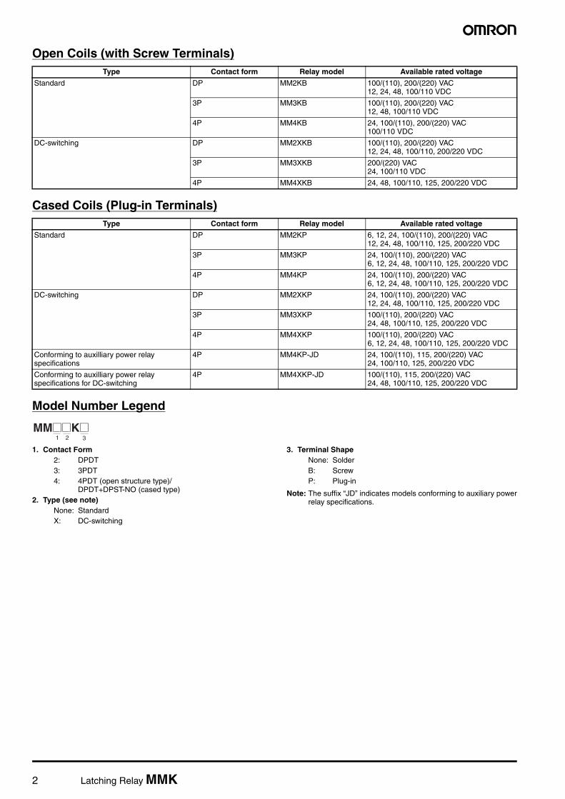
Open Coils (with Screw Terminals)
Cased Coils (Plug-in Terminals)
Model Number Legend
1. Contact Form2: DPDT3: 3PDT4: 4PDT (open structure type)/
DPDT+DPST-NO (cased type)2. Type (see note)
None: StandardX: DC-switching
3. Terminal ShapeNone: SolderB: ScrewP: Plug-in
Note: The suffix “JD” indicates models conforming to auxiliary powerrelay specifications.
Type Contact form Relay model Available rated voltage
Standard DP MM2KB 100/(110), 200/(220) VAC12, 24, 48, 100/110 VDC
3P MM3KB 100/(110), 200/(220) VAC12, 48, 100/110 VDC
4P MM4KB 24, 100/(110), 200/(220) VAC100/110 VDC
DC-switching DP MM2XKB 100/(110), 200/(220) VAC12, 24, 48, 100/110, 200/220 VDC
3P MM3XKB 200/(220) VAC24, 100/110 VDC
4P MM4XKB 24, 48, 100/110, 125, 200/220 VDC
Type Contact form Relay model Available rated voltage
Standard DP MM2KP 6, 12, 24, 100/(110), 200/(220) VAC12, 24, 48, 100/110, 125, 200/220 VDC
3P MM3KP 24, 100/(110), 200/(220) VAC6, 12, 24, 48, 100/110, 125, 200/220 VDC
4P MM4KP 24, 100/(110), 200/(220) VAC6, 12, 24, 48, 100/110, 125, 200/220 VDC
DC-switching DP MM2XKP 24, 100/(110), 200/(220) VAC12, 24, 48, 100/110, 125, 200/220 VDC
3P MM3XKP 100/(110), 200/(220) VAC24, 48, 100/110, 125, 200/220 VDC
4P MM4XKP 100/(110), 200/(220) VAC6, 12, 24, 48, 100/110, 125, 200/220 VDC
Conforming to auxilliary power relay specifications
4P MM4KP-JD 24, 100/(110), 115, 200/(220) VAC24, 100/110, 125, 200/220 VDC
Conforming to auxilliary power relay specifications for DC-switching
4P MM4XKP-JD 100/(110), 115, 200/(220) VAC24, 48, 100/110, 125, 200/220 VDC
MM@@K@1 2 3

Latching Relay MMK 3
Accessories (Order Separately)
Sockets
Mounting Brackets
Specifications
Coil Ratings
Set Coil
Note: 1. The rated current and coil resistance are measured at a coil temperature of 23°C with tolerances of +15%/–20% for AC rated current and±15% for DC coil resistance.
2. Performance characteristic data are measured at a coil temperature of 23°C.3. The AC coil resistance values are reference values.4. The maximum voltage is one that is applicable instantaneously to the Relay coil at an ambient temperature of 23°C and not continuously.∗Values in parentheses are for open relays.
Relay DIN Track/Front-connecting Socket Back-connecting Socket
Screw terminals Solder terminals
MM2(X)KP
MM3(X)KPMM4(X)KP
14PFA PL15
MM4(X)KP-JD 14PFA ---
Contact form Model
DPDT R99-03MM2K
3PDT R99-03MM3K
4PDT R99-03MM4K
11PFA PL11
Rated voltage (V)
Rated current (mA) Coil resistance (Ω)
Set volt.
Max volt.
Power consumption (VA or W)DP 3P, 4P
Open Relays Cased Open Relays Cased
50 Hz 60 Hz 50 Hz 60 Hz 50 Hz 60 Hz 50 Hz 60 Hz DP 3P, 4P % of rated voltage
AC 6 790 655 690 590 1,285 1,100 1,165 1,000 1.1 0.46 80% max.
110% Initial: DP: Approx. 6.23P, 4P: Approx. 12Rated:DP: Approx. 3.5 (3.9)3P, 4P: Approx. 6 (6.6)∗
12 395 325 345 295 640 550 580 500 4.7 1.9
24 195 160 170 145 320 275 290 250 19 8.2
50 94 78 82 70 154 132 140 120 82 34
100/ (110)
47 39/45 41 35/40 77 66/76 70 60/68 340 141
200/ (220)
23.5 19.5/22.5
20.5 17.5/20
38.5 33/38 35 30/34 1,540 563
DC 6 340 450 17.5 13.4 DP: Approx. 2.13P, 4P: Approx. 2.712 176 220 68 54
24 87 94 275 255
48 41 52 1,180 930
100/110
17/19 22/24.5 5,750 4,500
200/220
8.6/9.5 11/12 23,200 18,000

4 Latching Relay MMK
Reset Coil
Note: 1. The rated current and coil resistance are measured at a coil temperature of 23°C with tolerances of +15%/–20% for AC rated current and±15% for DC coil resistance.
2. Performance characteristic data are measured at a coil temperature of 23°C.3. The AC coil resistance values are reference values.4. The maximum voltage is one that is applicable instantaneously to the Relay coil at an ambient temperature of 23°C and not continuously.
Coils (Conforming to Auxiliary Power Relay Specifications)
Note: 1. The rated current and coil resistance are measured at a coil temperature of 23°C with tolerances of +15%/–20% for AC rated current and±15% for DC coil resistance.
2. The AC coil resistance and coil inductance values are for reference only.3. Performance characteristic data are measured at a coil temperature of 23°C.4. The maximum voltage is one that is applicable instantaneously to the Relay coil at an ambient temperature of 23°C and not continuously.
Rated voltage (V) Rated current (mA) Coil resistance (Ω)
Reset voltage Maximum voltage Power consumption(VA or W)50 Hz 60 Hz % of rated voltage
AC 6 770 690 2.3 80% max. 110% Initial: Approx. 6.5Rated:Approx. 4.112 385 345 9.2
24 191 170 35
50 92 82 175
100/(110) 46 41/46 739
200/(220) 23 20/23 3,030
DC 6 422 14.2 Approx. 2.8
12 215 56
24 109 220
48 58 832
100/110 25/27 4,040
200/220 12.2/13.5 16,330
Rated voltage (V)
Rated current (mA) Coil resistance (Ω)
Set voltage
Reset voltage
Max. voltage
Operation
level (JEC-174D)
Power consumption (VA or W)
Set coil Reset coil Set coil
Reset coil
Set coil Reset coil
50 Hz 60 Hz 50 Hz 60 Hz % of rated voltage Initial Rated Initial Rated
AC 24 245 210 191 170 8.5 35 80% max.
80% max.
110% A Approx. 6.3
Approx. 5.1
Approx. 6.5
Approx. 4.150 117 102 92 82 36 175
100/ (110)
58.5 51/58 46 41/46 150 739
110 53 46 42 37.3 182 835
115 51 44 40 35.7 210 885
200/ (220)
29 25.5/ 29
23 20.5/ 23
620 3,030
220 26.5 23 21 18.6 780 3,420
DC 24 94 109 255 220 Approx. 2.7 Approx. 2.8
48 52 58 930 832
100/ 110
22/24.5 25/27 4,500 4,040
125 22 23.5 5,800 5,330
200/ 220
11/12 12.2/13.5 18,000 16,330

Latching Relay MMK 5
Contact Ratings
Standard Relays
DC-switching Relays
Note: 1. When switching DC inductive loads at 125 V or more, an unstable region exists for a switching current of between 0.5 and 2.5 A. The Relay will not turn OFF in this region. Use a switching current of 0.5 A or less when switching 125 VDC or more.
2. If L/R exceeds 7 ms when switching DC inductive loads, an arc-breaking time of up to 50 ms must be considered in application and thecircuit must be designed to ensure that an arc-breaking time of 50 ms is not exceeded.
Contacts (Conforming to Auxiliary Power Relay Specifications)
Note: 1. When switching DC inductive loads at 125 V or more, an unstable region exists for a switching current of between 0.5 and 2.5 A. The Relay will not turn OFF in this region. Use a switching current of 0.5 A or less when switching 125 VDC or more.
2. If L/R exceeds 7 ms when switching DC inductive loads, an arc-breaking time of up to 50 ms must be considered in application and thecircuit must be designed to ensure that an arc-breaking time of 50 ms is not exceeded.
Item Open Relays: MM2K(B), MM3K(B), MM4K(B) Cased Relays: MM2KP, MM3KP, MM4KP
Resistive load (cosφ = 1)
Inductive load (cosφ=0.4, L/R=7 ms)
Resistive load (cosφ = 1)
Inductive load (cosφ=0.4, L/R=7 ms)
Contact mechanism Single
Contact material Ag
Rated load 10 A at 220 VAC7 A at 24 VDC
5 A at 220 VAC 4 A at 24 VDC
Rated carry current 10 A 5 A
Max. switching voltage 250 VAC, 250 VDC 250 VAC, 250 VDC
Max. switching current 10 A 5 A
Max. switching power(reference value)
2,200 VA, 168 W 1,100 VA, 96W
Item Open Relays: MM2XK(B), MM3XK(B), MM4XK(B) Cased Relays: MM2XKP, MM3XKP, MM4XKP
Resistive load (cosφ = 1)
Inductive load (cosφ=0.4, L/R=7 ms)
Resistive load (cosφ = 1)
Inductive load (cosφ=0.4, L/R=7 ms)
Contact mechanism Single
Contact material Ag
Rated load 7 A at 110 VDC 6 A at 110 VDC 5 A at 110 VDC
Rated current flow 10 A 5 A
Max. switching voltage 250 VAC, 250 VDC 250 VAC, 250 VDC
Max. switching current 10 A 5 A
Max. switching power(reference value)
800 W, 20 VA 660 W, 20 VA 700 W, 20 VA 600 W, 20 VA
Item MM4KP-JD MM4XKP-JD
Resistive load (cosφ = 1)
Inductive load(cosφ = 0.4, L/R= 7 ms)
Resistive load (cosφ = 1)
Inductive load(cosφ = 0.4, L/R= 7 ms)
Contact mechanism Single
Contact material Ag
Rated load 5 A at 220 VAC, 4 A at 24 VDC 5 A at 110 VDC
Rated carry current 5 A
Max. switching voltage 250 VAC, 250 VDC
Max. switching current 5 A

6 Latching Relay MMK
Characteristics
Note: 1. The data shown above are initial values.2. The contact resistance was measured with 1 A at 5 VDC using the voltage drop method.3. The set or reset time was measured with the rated voltage imposed with any contact bounce ignored at an ambient temperature of 23°C.4. The insulation resistance was measured with a 500-VDC megger applied to the same places as those used for checking the dielectric
strength.5. The electrical endurance was measured at an ambient temperature of 23°C.6. This value was measured at a switching frequency of 60 operations per minute.
Characteristics (Conforming to Auxiliary Power Relay Specifications)
Note: 1. The data shown above are initial values.2. The electrical endurance was measured at an ambient temperature of 23°C.3. This value was measured at a switching frequency of 60 operations per minute.
Item Open or bifurcated-contact Relays
Contact resistance (see note 2) 50 mΩ max.
Set time (see note 3) AC: 30 ms max.; DC: 60 ms max. (minimum pulse width for AC and DC: 100 ms)
Reset time (see note 3) 30 ms max. (minimum pulse width for AC and DC: 100 ms)
Max. operating frequency Mechanical: 1,800 operations/hrElectrical: 1,800 operations/hr (under rated load)
Insulation resistance (see note 4) 100 MΩ min. (at 500 VDC)
Dielectric strength 1,500 VAC, 50/60 Hz for 1 min between contacts of same polarity2,000 VAC, 50/60 Hz for 1 min between contacts of different polarity, between contacts and coil, and between set and reset coils
Vibration resistance Destruction: 10 to 55 to 10 Hz, 0.375 mm single amplitude (0.75 mm double amplitude)Malfunction: 10 to 35 to 10 Hz, 0.5 mm single amplitude (1.0 mm double amplitude)
Shock resistance Destruction: 500 m/s2
Malfunction: 50 m/s2
Endurance Mechanical: 2,500,000 operations min. (at 1,800 operations/hr)Electrical: 500,000 operations min. (at 1,800 operations/hr under rated load) (see note 5)
Error rate (level P)(Reference value)(see note 6)
10 mA at 5 VDC
Ambient temperature Operating: –10°C to 55°C (with no icing or condensation)
Ambient humidity Operating: 5% to 85%
Weight Standard Relays DC-switching RelaysMM2K: Approx. 255 g MM2XK: Approx. 260 gMM3K: Approx. 390 g MM2XK: Approx. 395 gMM4K: Approx. 420 g MM4XK: Approx. 430 gMM2KP: Approx. 375 g MM2XKP: Approx. 380 gMM3KP: Approx. 550 g MM3XKP: Approx. 555 gMM4KP: Approx. 570 g MM4XKP: Approx. 580 g
Vibration resistance Destruction: 10 to 55 to 10 Hz, 0.375 mm single amplitude (0.75 mm double amplitude)Malfunction: 10 to 22 to 10 Hz, 0.5 mm single amplitude (1.0 mm double amplitude)
Shock resistance Destruction: 300 m/s2
Malfunction: 30 m/s2
Endurance Mechanical: 2,500,000 operations min. (at 1,800 operations/hr)Electrical: 500,000 operations min. (at 1,800 operations/hr under rated load) (see note 2)
Error rate (level P)(Reference value)(see note 3)
10 mA at 5 VDC
Ambient temperature Operating: –10°C to 40°C (with no icing or condensation)
Ambient humidity Operating: 5% to 85%
Weight MM4KP-JD: Approx. 570 gMM4XKP-JD: Approx. 580 g

Latching Relay MMK 7
Engineering Data
Standard Relays
DC-switching Relays
Maximum Switching PowerOpen Relays
Switching voltage (V)
Cased Relays
Sw
itchi
ng c
urre
nt (
A)
Sw
itchi
ng c
urre
nt (
A)AC resistive load
DC resistive load
DC inductive load (L/R = 7 ms)
AC inductive load(cosφ = 0.4)
Switching current (A)
AC resistive load
AC inductive load(cosφ = 0.4)
DC resistive load
DC inductive load (L/R = 7 ms)
MM@K(B) MM@KP
Endurance CurvesOpen Relays Cased Relays
Switching current (A)
220 VAC resistive loadInductive load(cosφ = 0.4)
24 VDC resistive loadInductive load L/R = 7 ms
Switching current (A)
220 VAC resistive loadInductive load(cosφ = 0.4)
24 VDC resistive loadInductive load L/R = 7 ms
10,000
1,000
500
300
5,000
3,000
End
uran
ce (
x10
ope
ratio
ns)
3
End
uran
ce (
x10
ope
ratio
ns)
3
10,000
1,000
500
300
5,000
3,000
MM@K(B) MM@KP
Maximum Switching PowerOpen Relays
Switching voltage (V)
Cased Relays
Switching voltage (V)
DC inductive loadL/R=7 ms
DC resistive load
DC inductive loadL/R=7 ms
DC resistive load
MM@XK(B) MM@XKP
Sw
itchi
ng c
urre
nt (
A)
Sw
itchi
ng c
urre
nt (
A)

8 Latching Relay MMK
Relays Conforming to Auxiliary Power Relay Specifications
Endurance CurvesOpen Relays Cased Relays
Switching current (A)Switching current (A)
110 VDC resistive load
110 VDC inductive load(L/R 7 ms)
110 VDC resistive load Inductive loadL/R=7 ms
End
uran
ce (
x10
ope
ratio
ns)
3
10,000
1,000
500
300
5,000
3,000
End
uran
ce (
x10
ope
ratio
ns)
3
10,000
1,000
500
300
5,000
3,000
MM@XK(B) MM@XKP
Maximum Switching PowerMM4KP-JD MMX4KP-JD
Endurance CurvesMM4KP-JD MM4XKP-JD
AC resistive loadAC inductive loadcosφ = 0.4
DC resistive load
DC inductive loadL/R = 7 ms
Switching voltage (V)
DC resistive load
DC inductive load L/R = 7 ms
Switching voltage (V)
End
uran
ce (
x 10
)4
220 VAC resistive loadInductive loadcosφ = 0.4
24 VDC resistive load Inductive loadL/R = 7 ms
Switching current (A)
End
uran
ce (
x 10
)4
110 VDC resistive load Inductive loadL/R = 7 ms
Switching current (A)
Sw
itchi
ng c
urre
nt (
A)
Sw
itchi
ng c
urre
nt (
A)
Latching Relay MMK 9
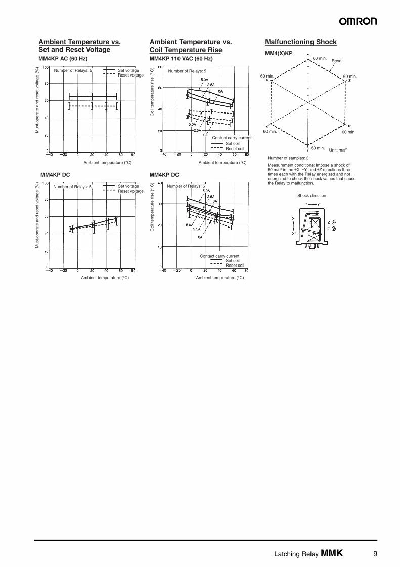
Ambient Temperature vs. Set and Reset VoltageMM4KP AC (60 Hz)
Ambient Temperature vs. Coil Temperature RiseMM4KP 110 VAC (60 Hz)
Malfunctioning Shock
MM4(X)KP
MM4KP DC MM4KP DC
Mus
t-op
erat
e an
d re
set v
olta
ge (
%)
Number of Relays: 5 Set voltageReset voltage
Ambient temperature (°C)
Coi
l tem
pera
ture
ris
e (
C)
° Number of Relays: 5
Contact carry currentSet coilReset coil
Ambient temperature (°C)
Reset60 min.
60 min. 60 min.
60 min.
60 min.
60 min.
Unit: m/s2
Number of samples: 3
Measurement conditions: Impose a shock of 50 m/s2 in the ±X, ±Y, and ±Z directions three times each with the Relay energized and not energized to check the shock values that cause the Relay to malfunction.
Mus
t-op
erat
e an
d re
set v
olta
ge (
%)
Number of Relays: 5 Set voltageReset voltage
Ambient temperature (°C)
Coi
l tem
pera
ture
ris
e (
C)
Number of Relays: 5
Contact carry currentSet coilReset coil
Ambient temperature (°C)
Shock direction
°

10 Latching Relay MMK
DimensionsNote: All units are in millimeters unless otherwise indicated.
Open Relays with Solder Terminals
Open Relays with Screw Terminals
86 max.
44 max.28±0.2
50 max.
94 max.
29±0.234
±0.2
MM2(X)K, MM3(X)K, MM4(X)K
MM2(X)K MM3(X)K
94 max.
63 max.
MM4(X)K
MM2K
15 max.
Two, M4 mounting holes
58.5 max.
Side View
2P 1P 3P 1P2P 4P 2P3P 1P Common C
Stationary A
Stationary B
Set coil
Reset coil
Note: Connect the common (C) of MM@XK to positive (+).
±0.222
22±0.2
MM2(X)KB, MM3(X)KB, MM4(X)KB
MM2KB
92 max.
Ten, M3.5 x 5.5 terminal screws
60 max.
MM2(X)KB
Thirteen,M3.5 x 5.5 terminal screws
101 max.
28±0.2
MM3(X)KB
Sixteen, M3.5 x 5.5 terminal screws
68 max.
34±0.2
101 max.
MM4(X)KB
15 max.
Two, M4 mounting holes
58.5 max.
29±0.2
Side View
60 max.
2P 1P 2P 1P3P 2P 1P3P4P Common C
Station-ary AStation-ary BSet coil
Reset coil
Note: Connect the common (C) of MM@XKB to positive (+).
Mounting Holes (Direct Mounting)Note: The tolerance is ±0.2.
Two, 4.5-dia. mounting holes
29±0.2Dimensions of : l2-pole: 22±0.2 mm3-pole: 28±0.2 mm4-pole: 34±0.2 mm
l
Mounting Bracket (S Bracket)R99-03MM ( )K
The S Bracket can be used to mount a Relay with open solder or screw terminals.
W H
29±0.2 60±0.2 50D
l
Item R99-03MM2K (DPDT)
R99-03MM3K (3PDT)
R99-03MM4K (4PDT)
l 22±0.2 28±0.2 34±0.2
D 71 max. 71 max. 71 max.
W 33 max. 39 max. 45 max.
H 6 max. 6 max. 6 max.

Latching Relay MMK 11
Cased Relays with Plug-in Terminal
Cases on Models for Switching DC LoadsAs shown at the right, there are three holes with a 10-mm diameter in the case.
80.5 max.
Terminal Arrangement/Internal Connections (Bottom View)
Note: Connect the common (C) to positive (+). Make sure that all common connections are the same in polarity. The markings of the common connections on the casing all show "+" but the polarity of the common connections can be ei- ther all negative or all positive.
Standard RelaysMM2KP
DC-switching RelaysMM2XKP
MM2(X)KP
22
54.5 max. (see note)
119 max.
64.5 max.
3.5 7
MM2KP
5
RESET
SET
RESET
SETNote: It is recommended that 55 mm min. is allowed for this side because the MM2XKP has a curved protective plate on the side.
80.5 max.
Terminal Arrangement/Internal Connections (Bottom View)
Note: Connect the common (C) to positive (+). Make sure that all common connections are the same in polarity. The markings of the common connections on the casing all show "+" but the polarity of the common connections can be either all negative or all positive.
Standard Relays
MM3KP
DC-switching RelaysMM3XKP
MM3(X)KPMM4(X)KP 72.5 max.
(see note)123 max.
64.5 max.
MM4KP
MM4KP MM4XKP
Note: It is recommended that 73 mm min. is allowed for this side because the MM3XKP and MM4XKP have a curved protective plate on the side.
Case Protective PlateBe sure the polarity is correct when connecting Exposed Models.
This example is for the MN2XK. This also applies to models with 3 or 4 poles.

12 Latching Relay MMK
Accessories
Sockets
Note: When using the MM@KP-JD by itself, the PL15 Back-connecting Socket cannot be used.
Height with Socket
Relay model DIN Track/Front-connecting Socket Back-connecting Socket
Screw terminals Solder terminals
MM2(X)KP
MM3(X)KPMM4(X)KP
14PFA PL15
MM4(X)KP-JD 14PFA ---
MM4KP-JD
70.5 max.
72.5 max.123 max.
64.5 max.
Terminal Arrangement/Internal Connections (Bottom View)
Note: The MM4KP-JD is DPDT and DPST-NO.
MM4XKP-JD
70.5 max.
73 max.123 max.
64.5 max.
Note: The MM4XKP-JD is DPDT and DPST- NO. Make sure that all common connec- tions are the same in polarity. The mark- ings of the common connections on the casing all show "+" but the polarity of the common connections can be either all negative or all positive.
11PFA PL11
MM3KP MM3XKP MM4KP MM4XKPMM4(X)KP-JD
151.5
MM2KP MM2XKP
151
11PFA 14PFA
155147.5
DIN Track/Front-connecting Socket Back-connecting Socket
PL11 PL15
124 128MM2KP MM2XKP
MM3KP MM3XKP MM4KP MM4XKP
Note: @PFA can be both track-mounted and screw-mounted.

Latching Relay MMK 13
Safety PrecautionsRefer to Safety Precautions for All Relays.
MountingMake sure that the Relay is free from iron powder or iron core, otherwise the iron dust may adhere to the Relay. As a result the movable contact may not operate properly.
An arc may be generated between the contacts in switching operation. Be sure to keep combustible objects away from the Relay. If the arc will have a bad effect around the Relay, the use of a model with a casing is recommended.
A model switching DC load incorporates an insulation base with a small built-in permanent magnet. Be sure to keep magnets or ferrous objects away from the permanent magnet, otherwise the capacity of the maximum switching current may drop.
The PL Back-connecting Socket must be flush-mounted from the surface of the panel.
If two or more Relays are mounted together, make sure that a minimum space of 20 mm is provided between adjacent Relays.
Be sure to mount the Relay so that the movable contact is in the downward direction.
Connection• When connecting a load to the contact terminals of a model for
switching DC loads ("X" models), consider the polarity of the con-tact terminals so that the generated arcs on the adjacent poles willnot collide. (For example, if the common connections of the Relayare all positive or all negative, no arc collision will occur.)
• Use proper crimp terminals or 1.2- to 2-mm-dia. single-conductorwire to connect screw terminals.
Screw Terminal ModelDo not bend the coil terminals, otherwise the coil wire may be dis-connected. Make sure that the tightening torque applied to each ter-minal is 1.27 N • m and the insertion force is 49 N for 10 s.
Solder Terminal ModelMake sure that Relay terminals are free of flux or other foreign sub-stance before soldering the Relay terminals. Finish soldering theRelay terminals quickly, otherwise the coil wire may be broken.
Circuits• You cannot use single contact to demagnetize the set coil as shown
below.
• NC contacts can remain open for a few milliseconds when the resetcoil turns ON and OFF. NO contact can remain open for a few milli-seconds when the set coil turns ON and OFF while the Relay islatched. Design your circuits to allow for this.
• Do not allow voltage to be applied simultaneously to both the setand reset coil. If voltage is applied simultaneously, the Relay will beset.
• There is no reason to apply voltage to Latching Relays continu-ously because they will latch properly with a single pulse of suffi-cient width. Continuously applying voltage will only waste power.
• A model for DC loads incorporates a permanent magnetic for arcsuppression. Keep floppy disks away from the Relay, otherwise thedata on the floppy disk may be damaged.
• Arcing when switching DC power can cause nitric gas to be generated. The case of the MM@XKP contains holes to allow the gas to escape. This, however, makes it possible for dust and dirt to enter the case. Be sure to use the MM@XKP in a suitable environment.
20 mmmin.
MMK MMKNormal mounting direction
Latching Relay coilNC contact of the Relay
Load
MMK contact (NC)
The contact may fail to hold itself.
Relay coil
In the interest of product improvement, specifications are subject to change without notice.
ALL DIMENSIONS SHOWN ARE IN MILLIMETERS.
To convert millimeters into inches, multiply by 0.03937. To convert grams into ounces, multiply by 0.03527.


