The CO2STORE project – Statusby Dr. Ing. Tore A. Torp, Statoil, Norway
CSLF International Workshop on CSLF Projects,
Potsdam 29 September 2005
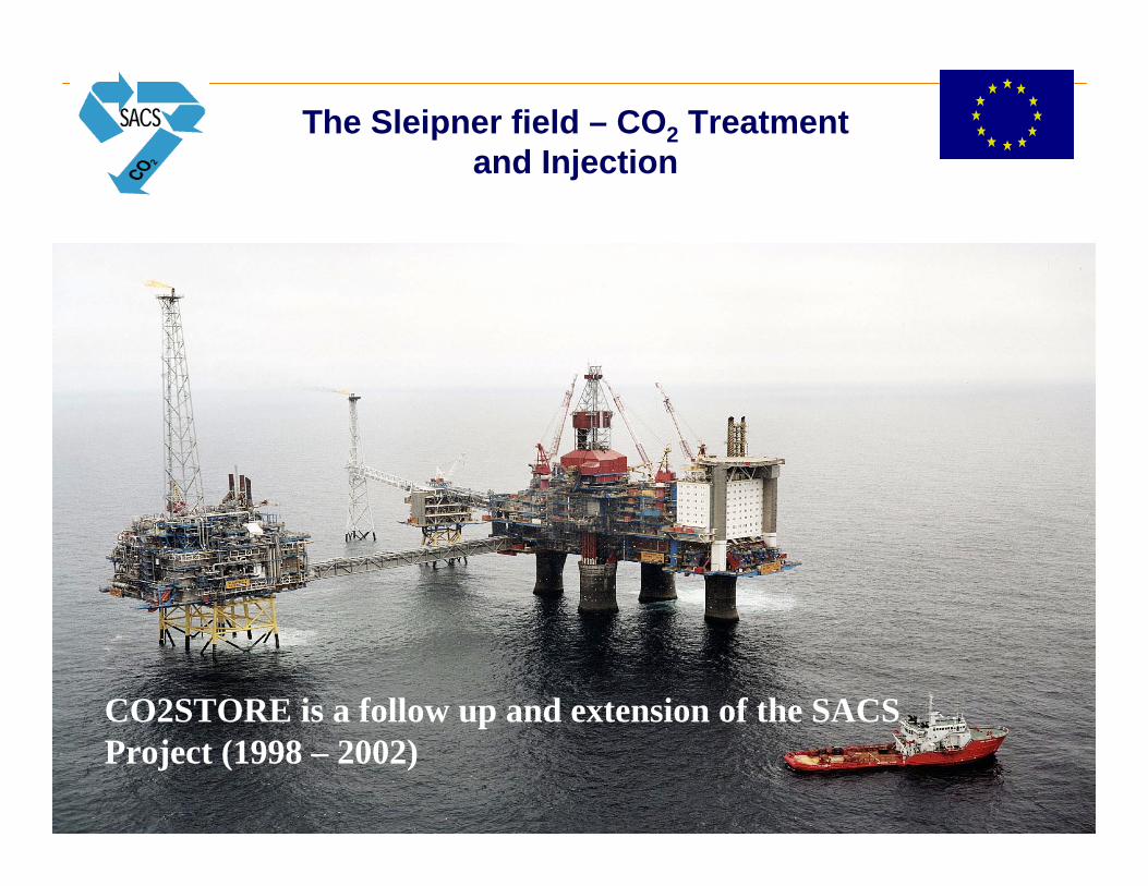
The Sleipner field – CO2 Treatment and Injection
CO2STORE is a follow up and extension of the SACSProject (1998 – 2002)
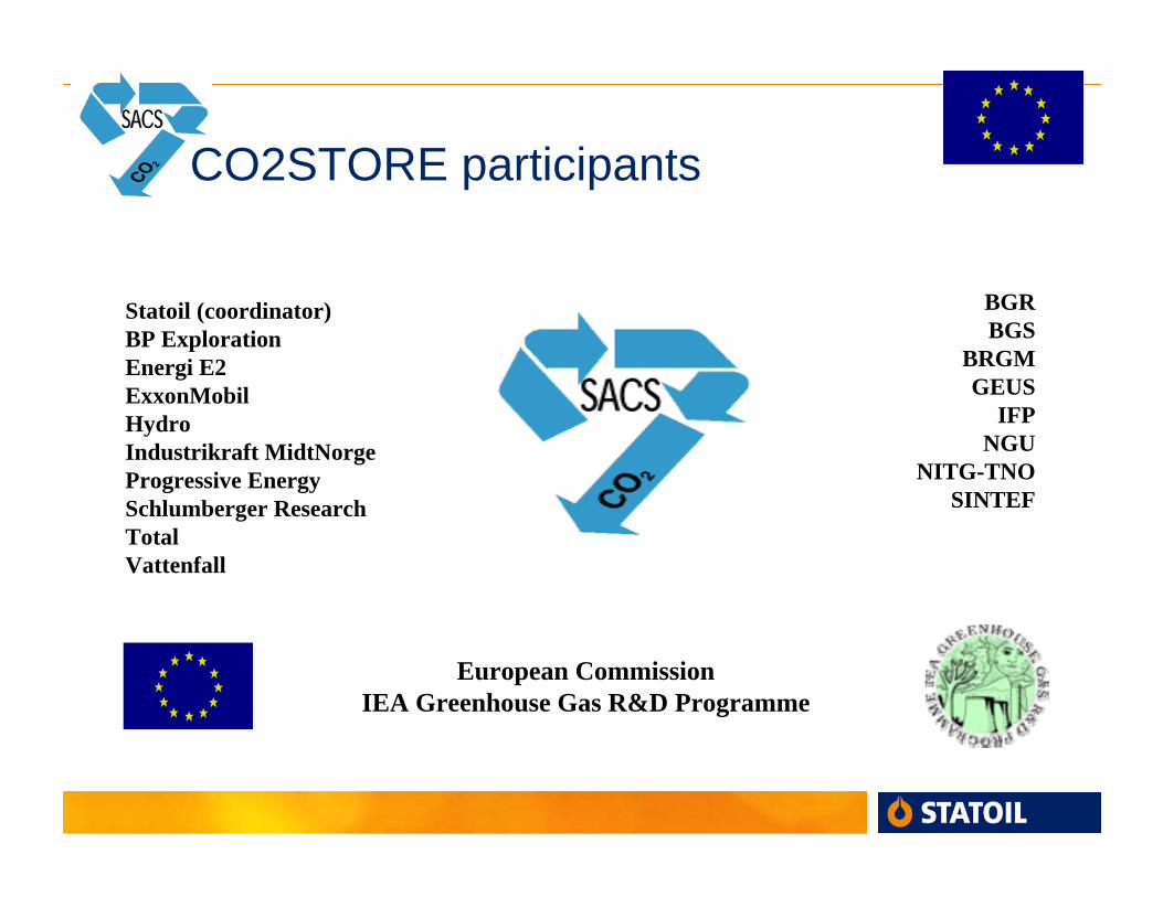
CO2STORE participants
Statoil (coordinator)BP ExplorationEnergi E2ExxonMobilHydroIndustrikraft MidtNorgeProgressive EnergySchlumberger ResearchTotalVattenfall
BGRBGS
BRGMGEUS
IFPNGU
NITG-TNOSINTEF
European CommissionIEA Greenhouse Gas R&D Programme
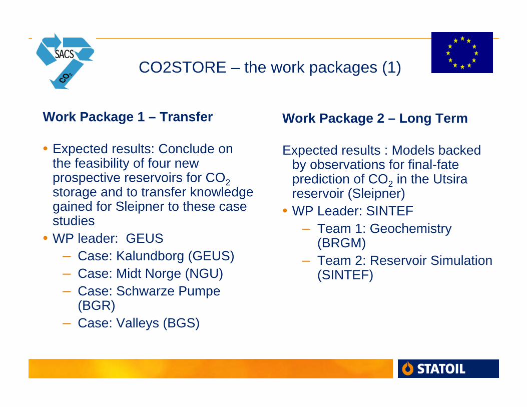
CO2STORE – the work packages (1)
Work Package 1 – Transfer
• Expected results: Conclude on the feasibility of four new prospective reservoirs for CO2storage and to transfer knowledge gained for Sleipner to these case studies
• WP leader: GEUS– Case: Kalundborg (GEUS)– Case: Midt Norge (NGU)– Case: Schwarze Pumpe
(BGR)– Case: Valleys (BGS)
Work Package 2 – Long Term
Expected results : Models backed by observations for final-fate prediction of CO2 in the Utsirareservoir (Sleipner)
• WP Leader: SINTEF– Team 1: Geochemistry
(BRGM)– Team 2: Reservoir Simulation
(SINTEF)
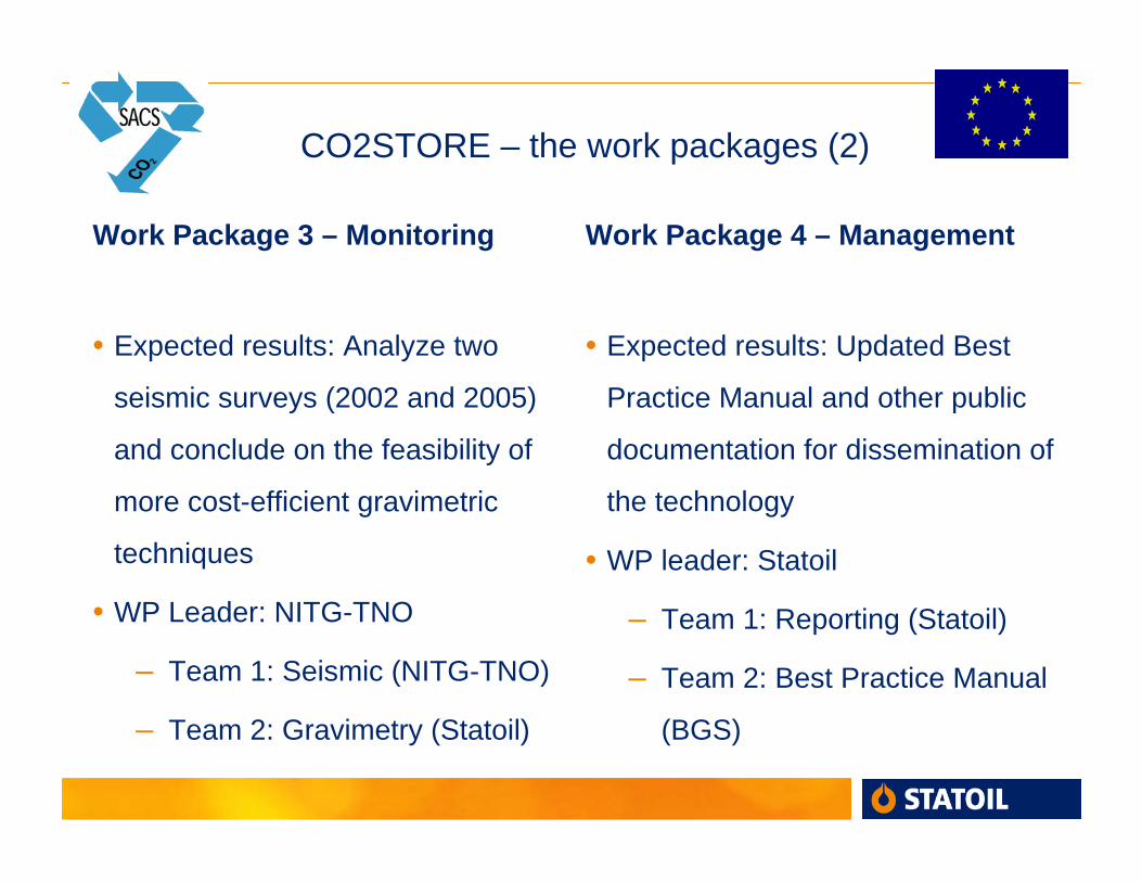
CO2STORE – the work packages (2)
Work Package 3 – Monitoring
• Expected results: Analyze two
seismic surveys (2002 and 2005)
and conclude on the feasibility of
more cost-efficient gravimetric
techniques
• WP Leader: NITG-TNO
– Team 1: Seismic (NITG-TNO)
– Team 2: Gravimetry (Statoil)
Work Package 4 – Management
• Expected results: Updated Best
Practice Manual and other public
documentation for dissemination of
the technology
• WP leader: Statoil
– Team 1: Reporting (Statoil)
– Team 2: Best Practice Manual
(BGS)
Risk assessment work in CO2STORE
• According to Description of Work for CO2STORE, all 4 case studies in
Work Package 1 shall produce ”Outline risk assessments (FEP and
scenario analysis)”
• Case Studies have chosen somewhat different approaches based on local
conditions
– Risk assessment Potential risks
• Common for all work packages: One day seminar/technical meeting
autumn 2004
• Risk assessment work is still ongoing and conclusions are preliminary
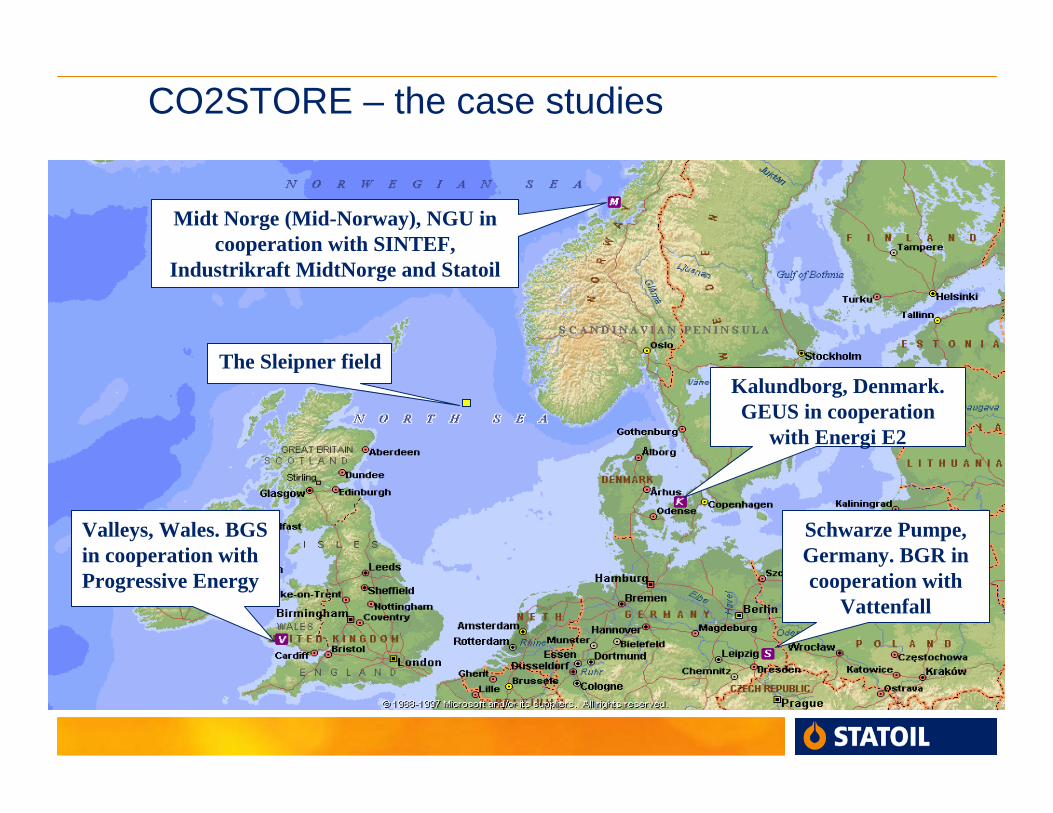
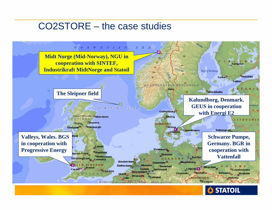
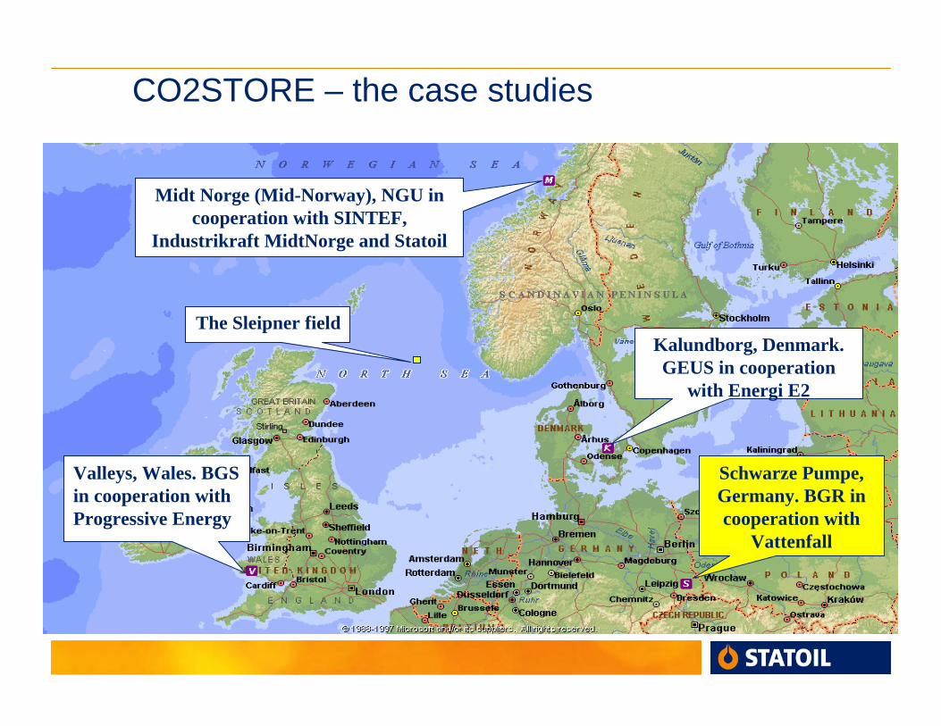
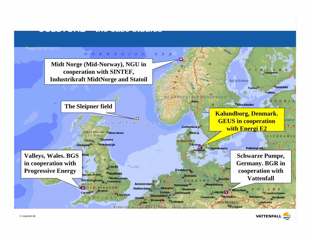
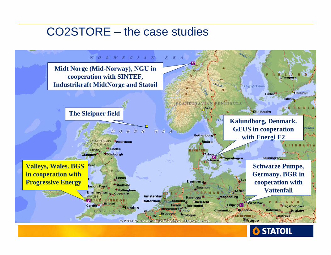
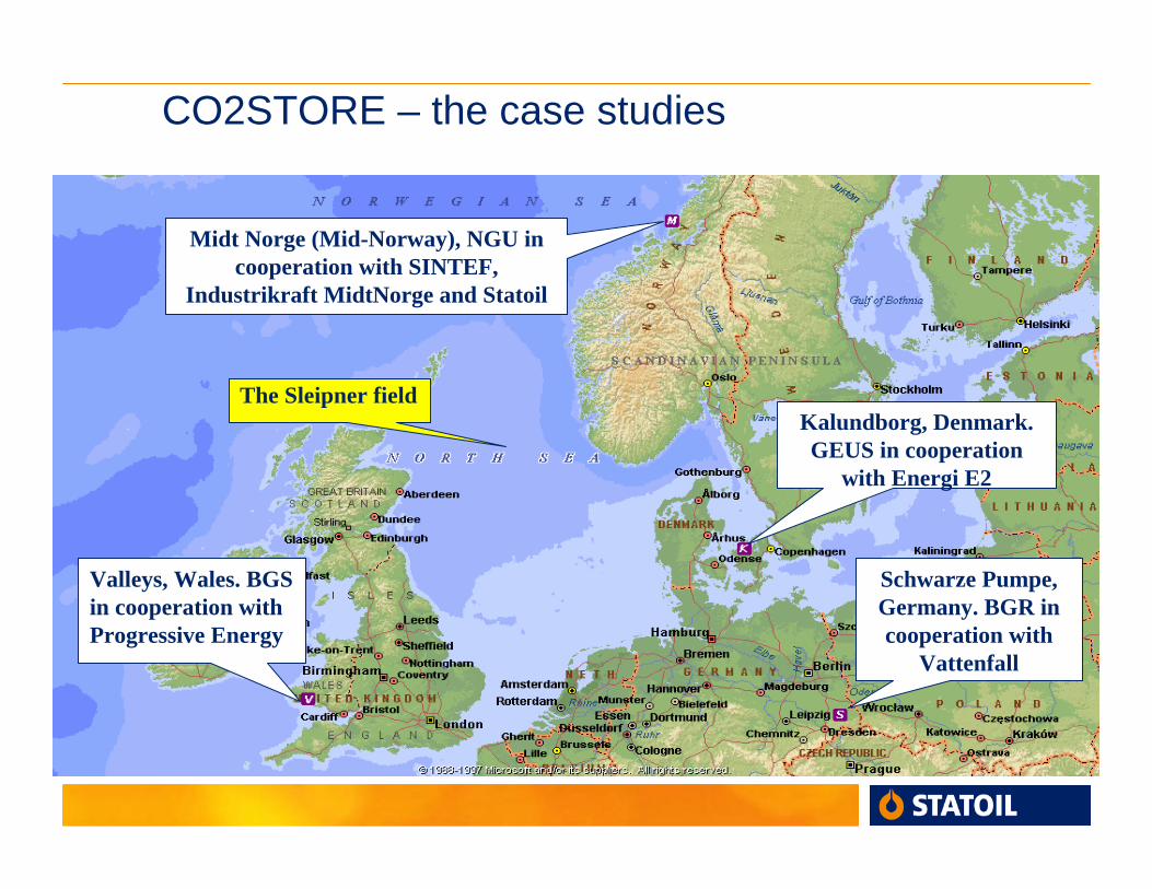
CO2STORE – the case studies
Kalundborg, Denmark. GEUS in cooperation
with Energi E2
Midt Norge (Mid-Norway), NGU in cooperation with SINTEF,
Industrikraft MidtNorge and Statoil
Valleys, Wales. BGS in cooperation withProgressive Energy
Schwarze Pumpe, Germany. BGR in cooperation with
Vattenfall
The Sleipner field
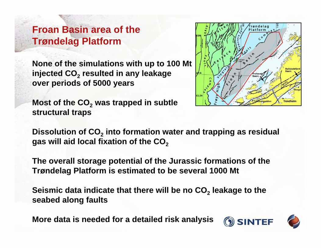
Froan Basin area of theTrøndelag Platform
None of the simulations with up to 100 Mtinjected CO2 resulted in any leakageover periods of 5000 years
Most of the CO2 was trapped in subtlestructural traps
Dissolution of CO2 into formation water and trapping as residualgas will aid local fixation of the CO2
The overall storage potential of the Jurassic formations of theTrøndelag Platform is estimated to be several 1000 Mt
Seismic data indicate that there will be no CO2 leakage to theseabed along faults
More data is needed for a detailed risk analysis
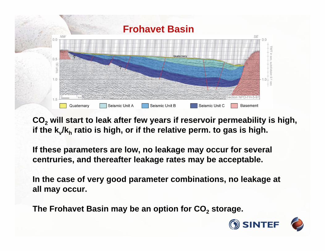
CO2 will start to leak after few years if reservoir permeability is high,if the kv/kh ratio is high, or if the relative perm. to gas is high.
If these parameters are low, no leakage may occur for severalcentruries, and thereafter leakage rates may be acceptable.
In the case of very good parameter combinations, no leakage atall may occur.
The Frohavet Basin may be an option for CO2 storage.
Frohavet Basin
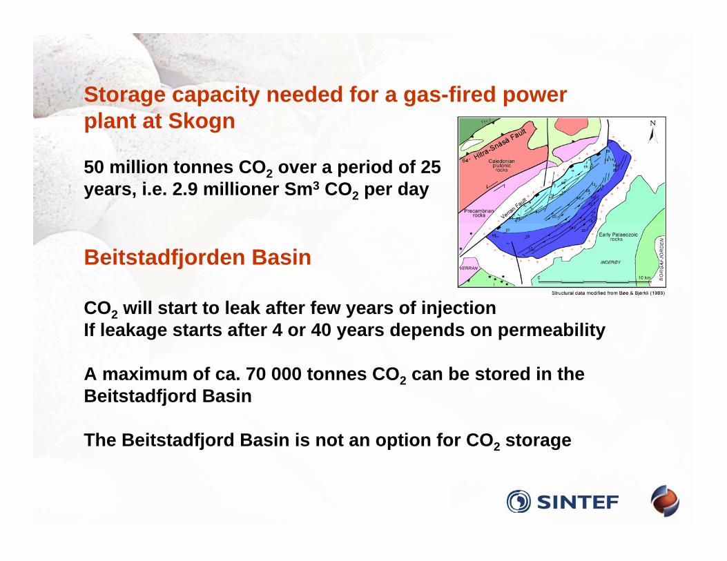
Storage capacity needed for a gas-fired powerplant at Skogn
50 million tonnes CO2 over a period of 25years, i.e. 2.9 millioner Sm3 CO2 per day
Beitstadfjorden Basin
CO2 will start to leak after few years of injectionIf leakage starts after 4 or 40 years depends on permeability
A maximum of ca. 70 000 tonnes CO2 can be stored in theBeitstadfjord Basin
The Beitstadfjord Basin is not an option for CO2 storage
CO2STORE – the case studies
Kalundborg, Denmark. GEUS in cooperation
with Energi E2
Midt Norge (Mid-Norway), NGU in cooperation with SINTEF,
Industrikraft MidtNorge and Statoil
Valleys, Wales. BGS in cooperation withProgressive Energy
Schwarze Pumpe, Germany. BGR in cooperation with
Vattenfall
The Sleipner field
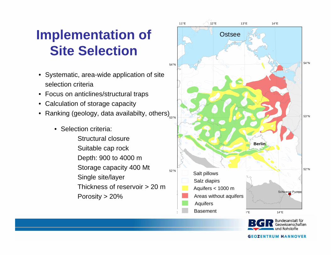
Implementation of Site Selection
• Systematic, area-wide application of site selection criteria
• Focus on anticlines/structural traps• Calculation of storage capacity• Ranking (geology, data availabilty, others)
• Selection criteria:• Structural closure• Suitable cap rock• Depth: 900 to 4000 m • Storage capacity 400 Mt• Single site/layer• Thickness of reservoir > 20 m• Porosity > 20% !.
Ostsee
Schwarze Pumpe
11°E
11°E
12°E
12°E 13°E
13°E
14°E
14°E
52°N 52°N
53°N 53°N
54°N 54°N
Salt pillowsSalz diapirsAquifers < 1000 mAreas without aquifersAquifersBasement
Berlin
Available Data…• Sound data set available from several surveys:
• Exploration for hydrocarbons (60th – 80th) • Hydrothermal energy survey (80th)• Nuclear waste repository
• Well data (60th – 80th)• Geophysical surveys (2D seismic, gravimetry, magnetotelluric (60th - 70th)
Summary:• area-wide sound knowledge of geological framework• Data from former surveys: formation boundaries, lithotypes, facies, …• no new seismic shot / no new wells drilled…
!.
Ostsee
561
406
707
1192
385
859388
540
489
Schwarze Pumpe
11°E
11°E
12°E
12°E 13°E
13°E
14°E
14°E
52°N 52°N
53°N 53°N
54°N 54°N
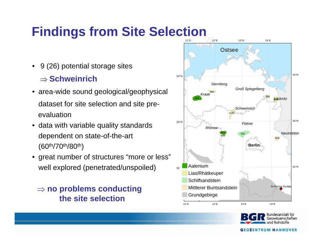
AaleniumLias/RhätkeuperSchilfsandsteinMittlerer BuntsandsteinGrundgebirge
Berlin
Findings from Site Selection
Schweinrich
Kraak
Sternberg
Löcknitz
Groß Spiegelberg
RhinowFlatow
Neutrebbin
• 9 (26) potential storage sites
⇒ Schweinrich• area-wide sound geological/geophysical
dataset for site selection and site pre-evaluation
• data with variable quality standards dependent on state-of-the-art (60th/70th/80th)
• great number of structures “more or less”well explored (penetrated/unspoiled)
⇒ no problems conductingthe site selection
© Vattenfall AB
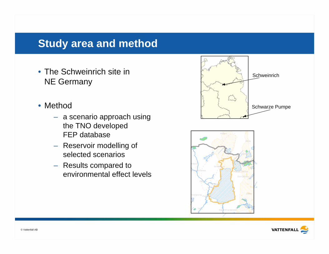
Study area and method
• The Schweinrich site in NE Germany
• Method – a scenario approach using
the TNO developed FEP database
– Reservoir modelling of selected scenarios
– Results compared to environmental effect levels
Teetz
Gadow
Mirow
Zühlen
Dossow
Biesen
Rägelin
Schwarz
Priborn
FretzdorfHerzsprung
Frankendorf
Schweinrich
Dorf-Zechlin
Flecken ZechlinWittstock/Dosse
Schweinrich
Schwarze Pumpe
© Vattenfall AB
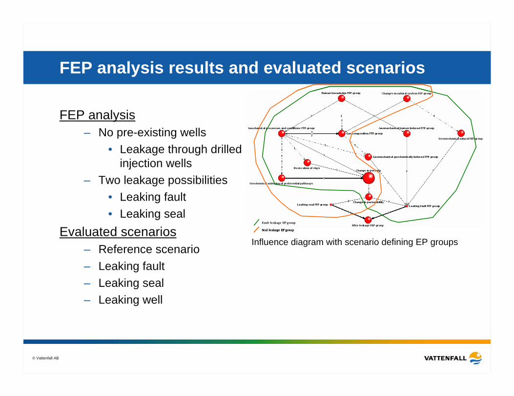
FEP analysis results and evaluated scenarios
FEP analysis– No pre-existing wells
• Leakage through drilled injection wells
– Two leakage possibilities• Leaking fault• Leaking seal
Evaluated scenarios– Reference scenario– Leaking fault– Leaking seal– Leaking well
Fault leakage EP group
Seal leakage EP group
Fault leakage EP group
Seal leakage EP group
Influence diagram with scenario defining EP groups
© Vattenfall AB
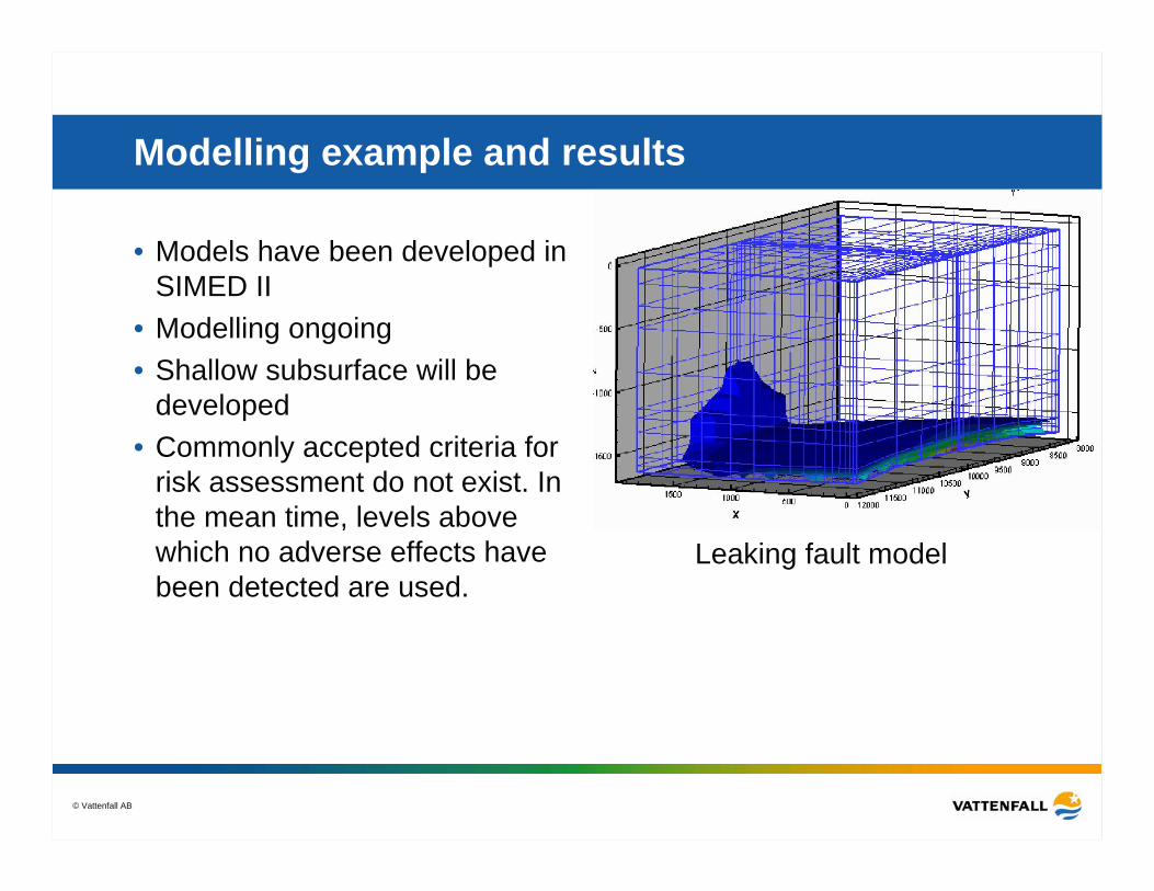
Modelling example and results
• Models have been developed in SIMED II
• Modelling ongoing• Shallow subsurface will be
developed• Commonly accepted criteria for
risk assessment do not exist. In the mean time, levels above which no adverse effects have been detected are used.
Leaking fault model
© Vattenfall AB
CO2STORE – the case studies
Kalundborg, Denmark. GEUS in cooperation
with Energi E2
Midt Norge (Mid-Norway), NGU in cooperation with SINTEF,
Industrikraft MidtNorge and Statoil
Valleys, Wales. BGS in cooperation with Progressive Energy
Schwarze Pumpe, Germany. BGR in cooperation with
Vattenfall
The Sleipner field
© Vattenfall AB
Photo EnergiE2Photo EnergiE2
Photo Energi E2Photo Energi E2
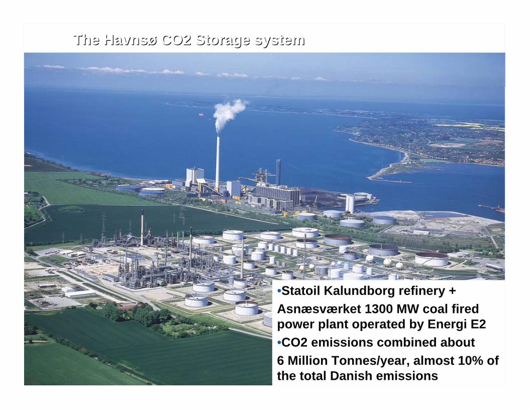
The The HavnsHavnsøø CO2 Storage systemCO2 Storage system
•Statoil Kalundborg refinery +Asnæsværket 1300 MW coal fired power plant operated by Energi E2•CO2 emissions combined about 6 Million Tonnes/year, almost 10% of the total Danish emissions
© Vattenfall AB
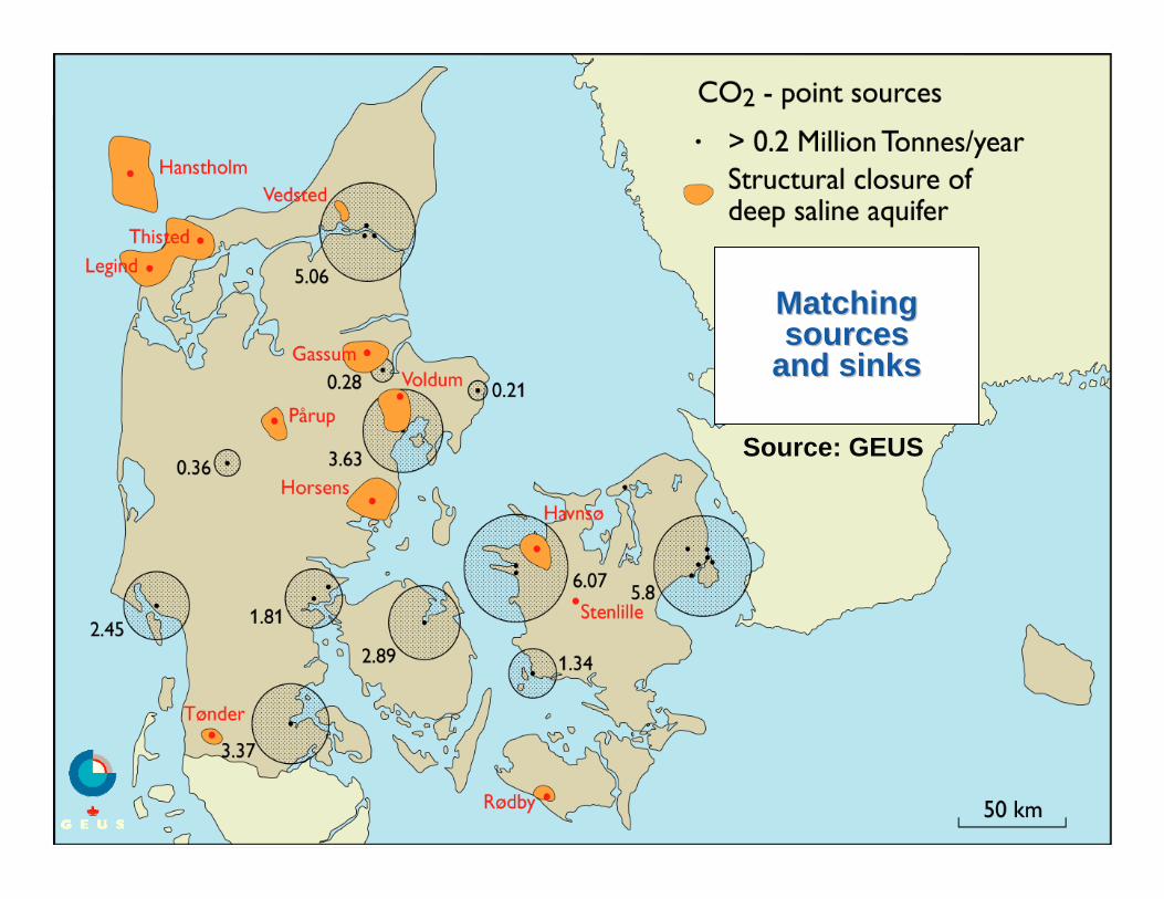
Matching Matching sources sources
and sinksand sinks
Source: GEUS
© Vattenfall AB
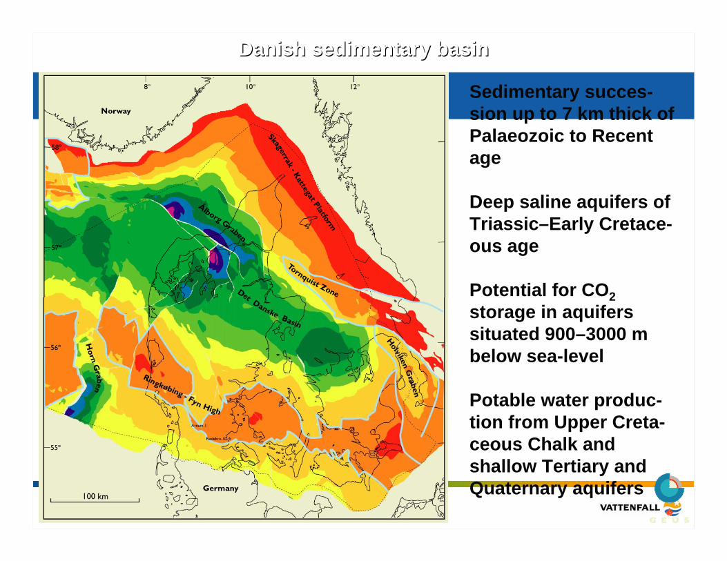
Danish sedimentary basinDanish sedimentary basin
Sedimentary succes-sion up to 7 km thick of Palaeozoic to Recent age
Deep saline aquifers of Triassic–Early Cretace-ous age
Potential for CO2storage in aquifers situated 900–3000 m below sea-level
Potable water produc-tion from Upper Creta-ceous Chalk and shallow Tertiary and Quaternary aquifers
© Vattenfall AB
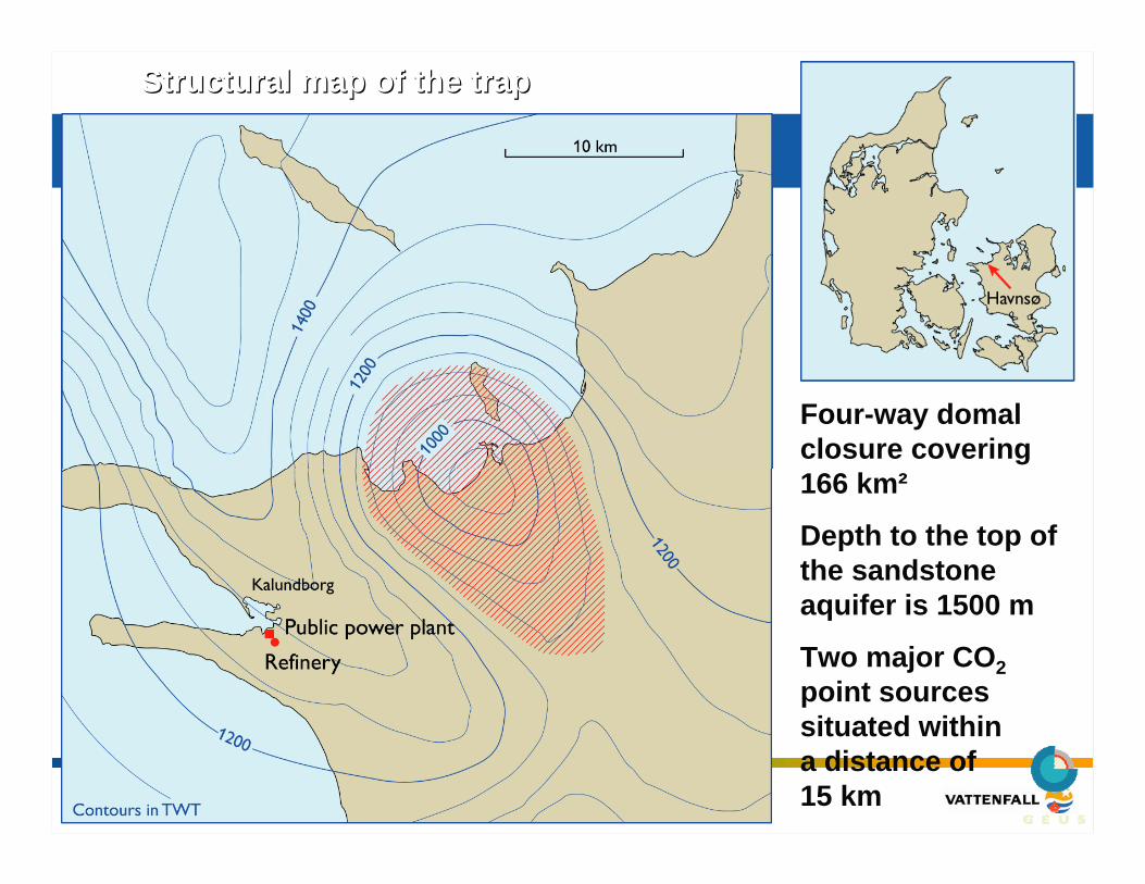
Structural map of the trapStructural map of the trap
Four-way domalclosure covering 166 km²
Depth to the top of the sandstone aquifer is 1500 m
Two major CO2point sources situated within a distance of 15 km
© Vattenfall AB
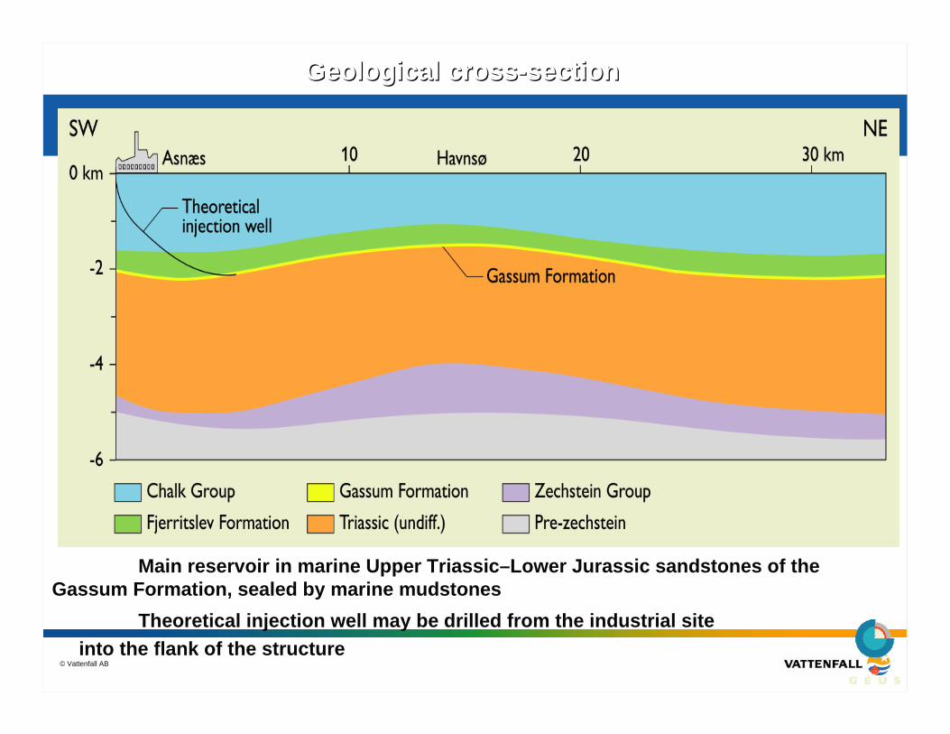
Geological crossGeological cross--sectionsection
Main reservoir in marine Upper Triassic–Lower Jurassic sandstones of the Gassum Formation, sealed by marine mudstones
Theoretical injection well may be drilled from the industrial site into the flank of the structure
CO2STORE – the case studies
Kalundborg, Denmark. GEUS in cooperation
with Energi E2
Midt Norge (Mid-Norway), NGU in cooperation with SINTEF,
Industrikraft MidtNorge and Statoil
Valleys, Wales. BGS in cooperation withProgressive Energy
Schwarze Pumpe, Germany. BGR in cooperation with
Vattenfall
The Sleipner field
© NERC All rights reserved
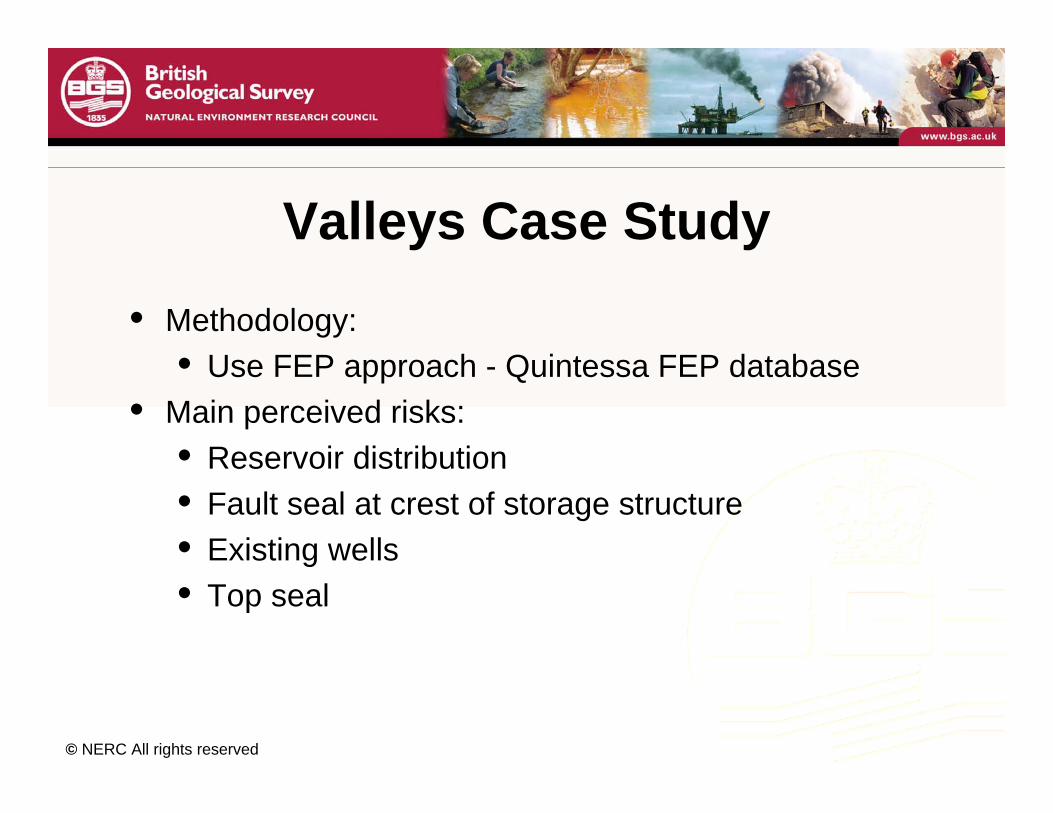
Valleys Case Study• Methodology:
• Use FEP approach - Quintessa FEP database• Main perceived risks:
• Reservoir distribution• Fault seal at crest of storage structure• Existing wells• Top seal
© NERC All rights reserved
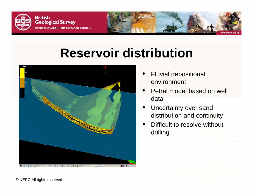
Reservoir distribution• Fluvial depositional
environment• Petrel model based on well
data• Uncertainty over sand
distribution and continuity• Difficult to resolve without
drilling
© NERC All rights reserved
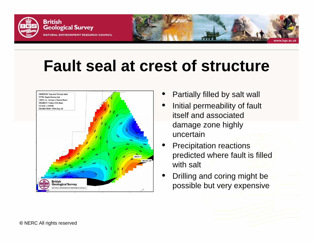
Fault seal at crest of structure• Partially filled by salt wall• Initial permeability of fault
itself and associated damage zone highly uncertain
• Precipitation reactions predicted where fault is filled with salt
• Drilling and coring might be possible but very expensive
© NERC All rights reserved
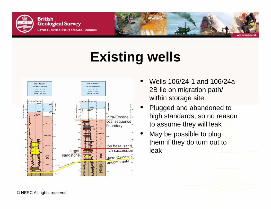
Existing wells• Wells 106/24-1 and 106/24a-
2B lie on migration path/ within storage site
• Plugged and abandoned to high standards, so no reason to assume they will leak
• May be possible to plug them if they do turn out to leak
© NERC All rights reserved
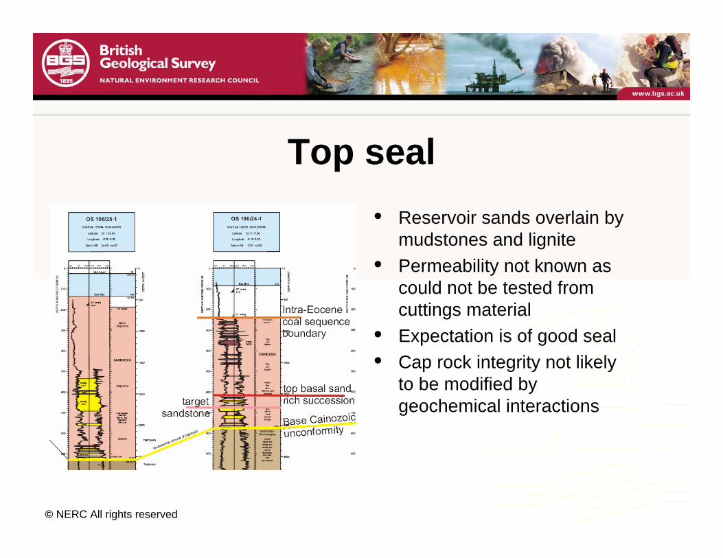
Top seal• Reservoir sands overlain by
mudstones and lignite• Permeability not known as
could not be tested from cuttings material
• Expectation is of good seal• Cap rock integrity not likely
to be modified by geochemical interactions
© NERC All rights reserved
Preliminary Conclusions Valleys• Now in the process to go through FEP process to
ensure the major risks have been identified• Since St. George’s Channel basin is poorly explored,
with only a handful of wells, the geological risks are much higher than in petroleum-bearing basins
• Simulations show all CO2 ends up next to the fault• The cost of reaching robust conclusions about
(1) whether the fault will leak or seal, and (2) whether there is sufficient reservoir sand,could be very high.
CO2STORE – the case studies
Kalundborg, Denmark. GEUS in cooperation
with Energi E2
Midt Norge (Mid-Norway), NGU in cooperation with SINTEF,
Industrikraft MidtNorge and Statoil
Valleys, Wales. BGS in cooperation withProgressive Energy
Schwarze Pumpe, Germany. BGR in cooperation with
Vattenfall
The Sleipner field
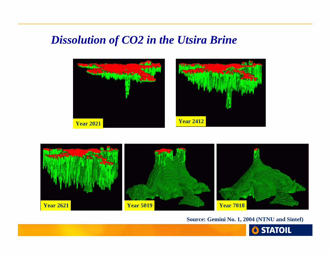
Dissolution of CO2 in the Utsira Brine
Year 2021 Year 2412
Year 2621 Year 5019 Year 7018
Source: Gemini No. 1, 2004 (NTNU and Sintef)
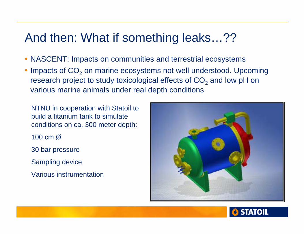
And then: What if something leaks…??• NASCENT: Impacts on communities and terrestrial ecosystems• Impacts of CO2 on marine ecosystems not well understood. Upcoming
research project to study toxicological effects of CO2 and low pH on various marine animals under real depth conditions
NTNU in cooperation with Statoil to build a titanium tank to simulate conditions on ca. 300 meter depth:
100 cm Ø
30 bar pressure
Sampling device
Various instrumentation
WAY FORWARD?
BUILD TRUST
• More geological settings
• Publish work and results
• Inform regulators, policymakers and public
• Inter-continental cooperation
LEGAL CLARIFICATION
• Mining and/or Petroleum laws adaptation
• OSPAR & LONDON Conventions