CS 552Computer NetworksQuality Of Service
Richard MartinCredit slides by B. Nath, I. Stoica

Outline
• What is Quality of Service• Basic mechanisms
– Leaky and token buckets• Integrated Services (IntServ)• Differentiated Services (DiffServ)• Economics and Social factors facing QoS

Best Effort vs. QoS
• Best Effort:– You get a link to the Internet with at most B
bits/sec.– If you don’t like it, switch to another provider.
• Quality of Service (Premium Service)– We provide you some kind of guarantees for:
• Bandwidth• Latency• Jitter
– I.e., network is engineered to provide someQuality beyond “whatever”

QoS’s Quest
The Holy Grail of computer networking is todesign a network that has the flexibility and
low cost of the Internet, yet offers the end-to-end quality-of-service guarantees of the
telephone network. --S. Keshav

Two Styles of QoS
• Worse-case– Provide bandwidth/delay/jitter guarantee to every
packet– E.g., “hard real time”
• Average-case– Provide bandwidth/delay/jitter guarantee over
many packets– Statistical in nature– E.g. “Soft real time”

Resource Reservation: Example
Router RouterSrc Dest4 Mbpsavailable
6 Mbpsavailable
10 Mbpsavailable
Case 1: Source attempts to connect to destination, and attempts to reserve 4 Mbps for the connection
Result: Connection accepted. There is enough bandwidth available. Available link bandwidths updated.
Case 2: Source attempts to connect to destination, and attempts to reserve 5 Mbps for the connection
Result: Failure. There is not enough bandwidth available on one of the links.

Resource Reservation (cont’d)
• Once a connection is accepted, the host must useonly the amount of resources reserved. It may notuse more than that.
• What if the host is malicious and attempts to usemore network resources than it reserved?

Leaky Bucket
• Used in conjunction with resource reservationto police the host’s reservation
• At the host-network interface, allow packetsinto the network at a constant rate
• Packets may be generated in a burstymanner, but after they pass through the leakybucket, they enter the network evenly spaced
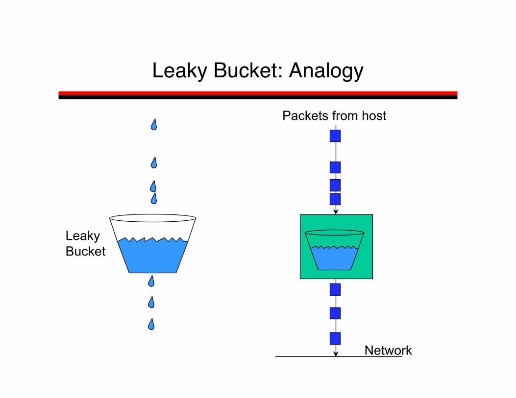
Leaky Bucket: Analogy
LeakyBucket
Network
Packets from host

Leaky Bucket (cont’d)
• The leaky bucket is a “traffic shaper”: It changes thecharacteristics of packet stream
• Traffic shaping makes more manageable and morepredictable
• Usually the network tells the leaky bucket the rate atwhich it may send packets when the connectionbegins
• Polices the average rate
Leaky Bucket:Doesn’t allow bursty transmissions
• In some cases, we may want to allow shortbursts of packets to enter the network withoutsmoothing them out
• For this purpose we use a token bucket,which is a modified leaky bucket
Token Bucket
• The bucket holds tokens instead of packets• Tokens are generated and placed into the token bucket at a
constant rate• When a packet arrives at the token bucket, it is transmitted if
there is a token available. Otherwise it is buffered until a tokenbecomes available.
• The token bucket has a fixed size, so when it becomes full,subsequently generated tokens are discarded
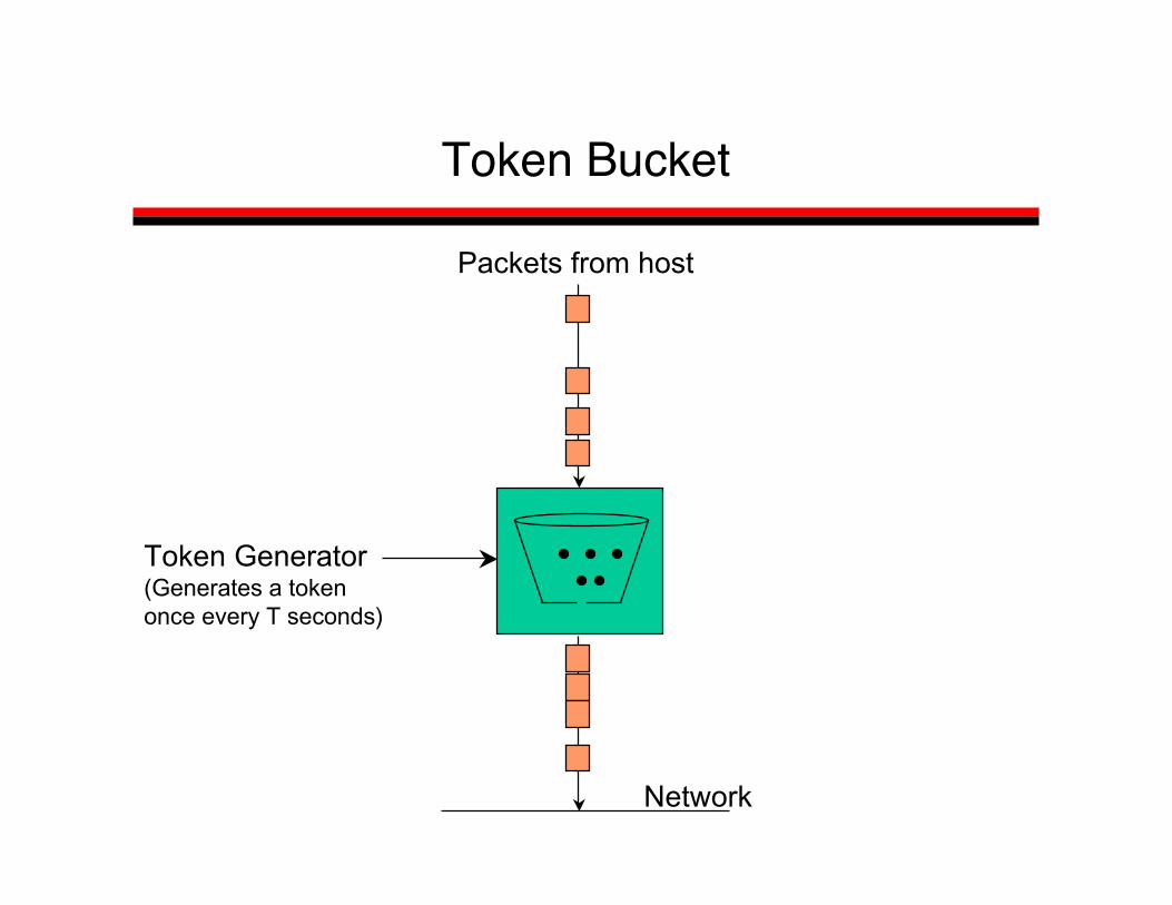
Token Bucket
Network
Packets from host
Token Generator(Generates a tokenonce every T seconds)

Token Bucket vs. Leaky Bucket
Case 1: Short burst arrivals
6543210
Arrival time at bucket
Departure time from a leaky bucketLeaky bucket rate = 1 packet / 2 time unitsLeaky bucket size = 4 packets
6543210
6543210
Departure time from a token bucketToken bucket rate = 1 tokens / 2 time unitsToken bucket size = 2 tokens

Token Bucket vs. Leaky Bucket
Case 2: Large burst arrivals
6543210
Arrival time at bucket
Departure time from a leaky bucketLeaky bucket rate = 1 packet / 2 time unitsLeaky bucket size = 2 packets
6543210
6543210
Departure time from a token bucketToken bucket rate = 1 token / 2 time unitsToken bucket size = 2 tokens

Flow Specification: Token Bucket
• Characterized by two parameters (r, b)– r – average rate– b – token depth
• Assume flow arrival rate <= R bps (e.g., R link capacity)• A bit is transmitted only when there is an available token• Arrival curve – maximum amount of bits transmitted by time t
r bps
b bits
<= R bps
regulatortime
bits
b
slope R
slope r
Arrival curve

Quality of service issues
• Flow specification– Flow spec: traffic characteristics, QoS requirements (delay,
jitter,bandwidth)• Routing
– Routing traffic to best meet demand• Resource reservation
– End-host signaling to network QoS resource requirements• Admission control
– Limiting number of reservations• Packet scheduling
– Packet by packet scheduling (fairness, delay)• RSVP addresses reservation

Integrated Services Example: Data Path
SenderReceiver
• Per-flow classification
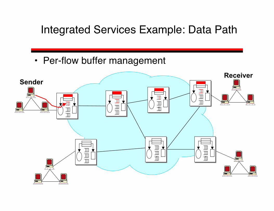
Integrated Services Example: Data Path
SenderReceiver
• Per-flow buffer management
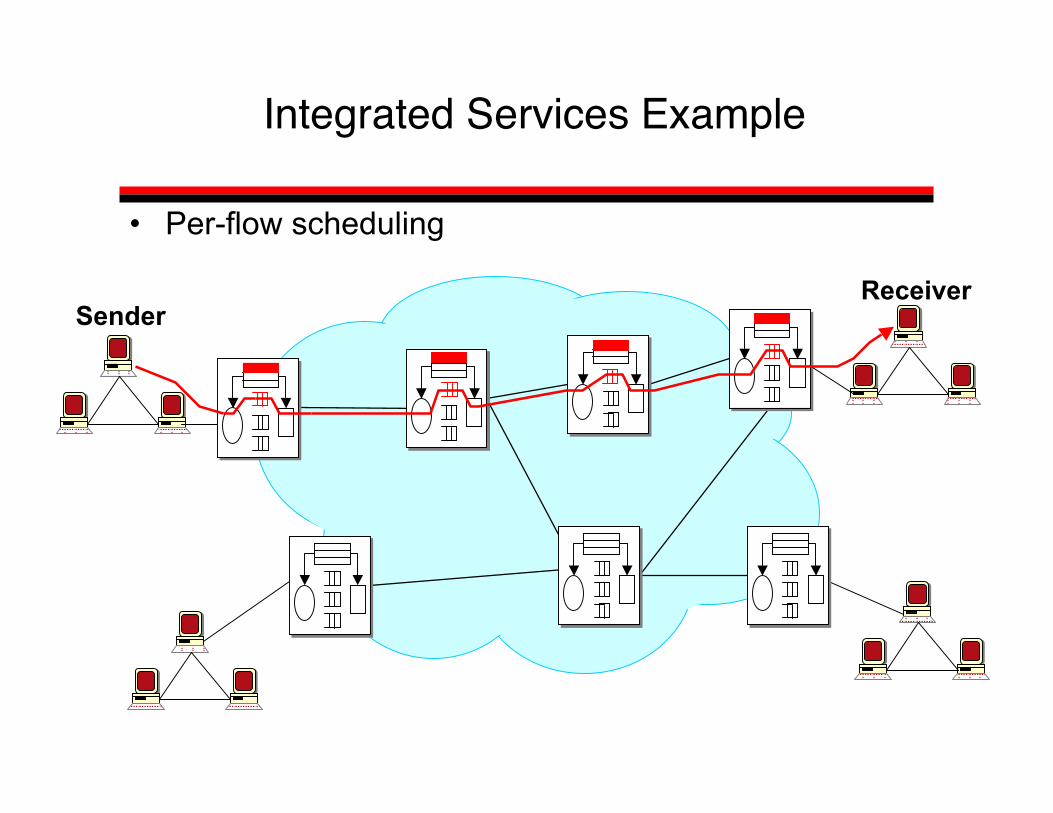
Integrated Services Example
SenderReceiver
• Per-flow scheduling

How Things Fit Together
Admission Control
Data InData Out
C
on
tro
l P
lan
eD
ata
P
lan
e
Scheduler
Routing Routing
MessagesRSVP
messages
Classifier
RSVP
Route Lookup
Forwarding Table Per Flow QoS Table

Service Classes
• Multiple service classes• Service: contract between network and
communication client– End-to-end service– Other service scopes possible
• Three common services– Best-effort (“elastic” applications)– Hard real-time (“real-time” applications)– Soft real-time (“tolerant” applications)

Worse-case : Guaranteed Services
• Service contract– Network to client: guarantee a deterministic upper
bound on delay for each packet in a session– Client to network: the session does not send more
than it specifies• Algorithm support
– Admission control based on worst-case analysis– Per flow classification/scheduling at routers

Average-case: Controlled Load Service
• Service contract:– Network to client: Average delay, jitter, bandwidth, e.g., makes
network appear as an unloaded, best effort network withbandwidth and delay
– Client to network: the session does not send more than itspecifies
• Algorithm Support– Admission control based on measurement of aggregates– Scheduling for aggregate possible

RSVP Usage andRelated Issues
25
Role of RSVP in the Architecture
• Signaling protocol for establishing per flowstate
• Carry resource requests from hosts torouters
• Collect needed information from routers tohosts
• At each hop– Consult admission control and policy module– Set up admission state or informs the requester
of failure

RSVP Design Features
• IP Multicast centric design• Receiver initiated reservation• Different reservation styles• Soft state inside network• Decouple routing from reservation

IP Multicast
• Best-effort MxN delivery of IP datagrams• Basic abstraction: IP multicast group
– Identified by Class D address: 224.0.0.0 - 239.255.255.255– Sender needs only to know the group address, but not the
membership– Receiver joins/leaves group dynamically
• Routing and group membership managed distributedly– No single node knows the membership– Tough problem– Various solutions: DVMRP, CBT, PIM

RSVP Reservation Model
• Performs signaling to set up reservation statefor a session
• A session is a simplex data flow sent to aunicast or a multicast address, characterizedby– <IP dest, protocol number, port number>
• Multiple senders and receivers can be insession

RSVP Usage andRelated Issues
29
The Big Picture
NetworkSender
Receiver
PATH Msg

RSVP Usage andRelated Issues
30
The Big Picture (2)
NetworkSender
Receiver
PATH Msg
RESV Msg

RSVP terminology
• Flow descriptor (Flow spec + Filter Spec)• Flow spec (Rate, max burst)
– Sender can Explicitly specify flow spec or not specify• Filter Spec (Sender address, TCP/UDP, Port#)
– Aids in combining similar flows– Filter can be shared (SE-style) or can use wild cards (all senders
on a given port or a given sender on all ports, etc)– The style may be shared or distinct in a sense that all reservations
may be handled as one single reservation or there may be a singlereservation for each upstream sender respectively.

RSVP Basic Operations
• Sender: sends PATH message via the data delivery path– Set up the path state each router including the address of
previous hop• Receiver sends RESV message on the reverse path
– Specifies the reservation style, QoS desired– Set up the reservation state at each router
• Things to notice– Receiver initiated reservation– Decouple routing from reservation– Two types of state: path and reservation

RSVP messages
• PATH message – sets up state along pathfollowed by packets
• RESV message – request for reservationback along setup path path
• PATH_TEAR, RESV_TEAR,RESV_CONFIRM, RESV_ERROR,PATH_ERROR

RSVP Operation
Sender
Receiver1 Receiver2Receiver3
Merged reservations
Merged reservations
RSVP PATH MESSAGE
• From sender to receiver (unicast or multicast)• Intercepted at each RSVP aware hop• Includes
– Sender TSpec : Traffic characteristics of the sender• Token bucket rate, depth, max flow rate, max packet size• forms one side of the ``contract'' between the data flow and the service.
– F-flag: specify whether filtered reservation is allowed• Routers store:
– Path state, i.e., PHOP address to previous hop (RSVP aware node)– If F-flag is set, store sender and its flowspec– Otherwise, just add new link to multicast tree
RSVP RESV MESSAGE
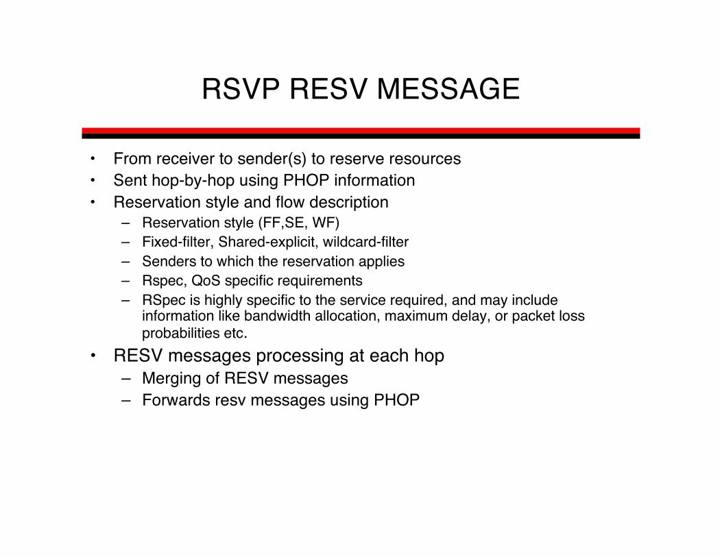
• From receiver to sender(s) to reserve resources• Sent hop-by-hop using PHOP information• Reservation style and flow description
– Reservation style (FF,SE, WF)– Fixed-filter, Shared-explicit, wildcard-filter– Senders to which the reservation applies– Rspec, QoS specific requirements– RSpec is highly specific to the service required, and may include
information like bandwidth allocation, maximum delay, or packet lossprobabilities etc.
• RESV messages processing at each hop– Merging of RESV messages– Forwards resv messages using PHOP

Route Pinning
• Problem: asymmetric routes– You may reserve resources on R‡S3‡S5‡S4‡S1‡S, but
data travels on S‡S1‡S2‡S3‡R !• Solution: use PATH to remember direct path from S to R,
i.e., perform route pinning
S1S1
S2S2
S3S3
SSRR
S5S5S4S4PATH
RESV
IP routing

How Is the Token Bucket Used?
• Can be enforced by– End-hosts (e.g., cable modems)– Routers (e.g., ingress routers in a Diffserv domain)
• Can be used to characterize the traffic sentby an end-host
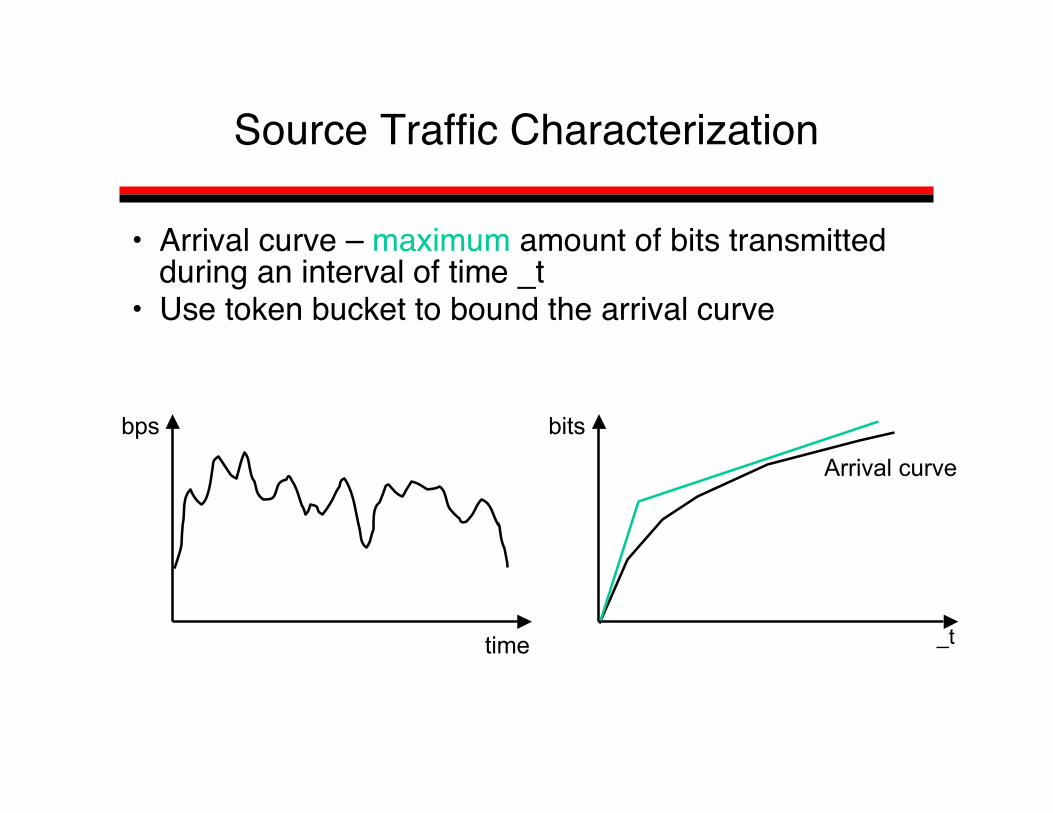
Source Traffic Characterization
• Arrival curve – maximum amount of bits transmittedduring an interval of time _t
• Use token bucket to bound the arrival curve
_t
bits
Arrival curve
time
bps

QoS Guarantees: Per-hop Reservation
• End-host: specify– the arrival rate characterized by token-bucket with parameters (b,r,R)– the maximum maximum admissible delay D
• Router: allocate bandwidth ra and buffer space Ba such that– no packet is dropped– no packet experiences a delay larger than D
bits
b*R/(R-r)
slope rArrival curve
DBa
slope ra
End-to-End Reservation
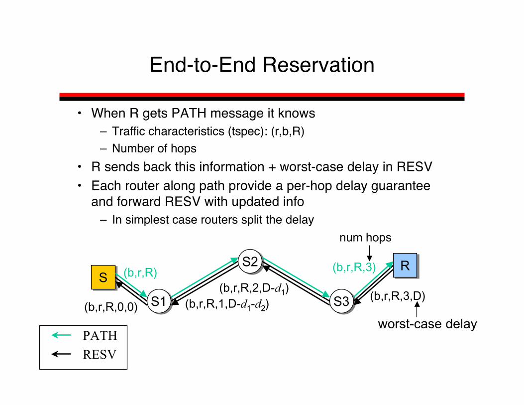
• When R gets PATH message it knows– Traffic characteristics (tspec): (r,b,R)– Number of hops
• R sends back this information + worst-case delay in RESV• Each router along path provide a per-hop delay guarantee
and forward RESV with updated info– In simplest case routers split the delay
S1S1
S2S2
S3S3
SSRR(b,r,R) (b,r,R,3)
num hops
(b,r,R,2,D-d1)(b,r,R,1,D-d1-d2)(b,r,R,0,0)
(b,r,R,3,D)
worst-case delayPATH
RESV

Reservation Style
• Motivation: achieve more efficient resourceutilization in multicast (M x N)
• Observation: in a video conferencing whenthere are M senders, only a few can be activesimultaneously– Multiple senders can share the same reservation
• Various reservation styles specify differentrules for sharing among senders

Reservation Styles and Filter Spec
• Reservation style– use filter to specify which sender can use the
reservation• Three styles
– Wildcard filter: does not specify any sender; all packetsassociated to a destination shares same resources
• Group in which there are a small number ofsimultaneously active senders
– Fixed filter: no sharing among senders, senderexplicitly identified for the reservation
• Sources cannot be modified over time– Dynamic filter: resource shared by senders that are
(explicitly) specified• Sources can be modified over time

Wildcard Filter Example
• Receivers: H1, H2; senders: H3, H4, H5• Each sender sends B• H1 reserves B; listen from one server at a time
S1S1 S2S2 S3S3
H2H2
H1H1
H5H5
H4H4
H3H3
(B,*)(B,*) (B,*)
(B,*)
(B,*)
(B,*)
senderreceiver
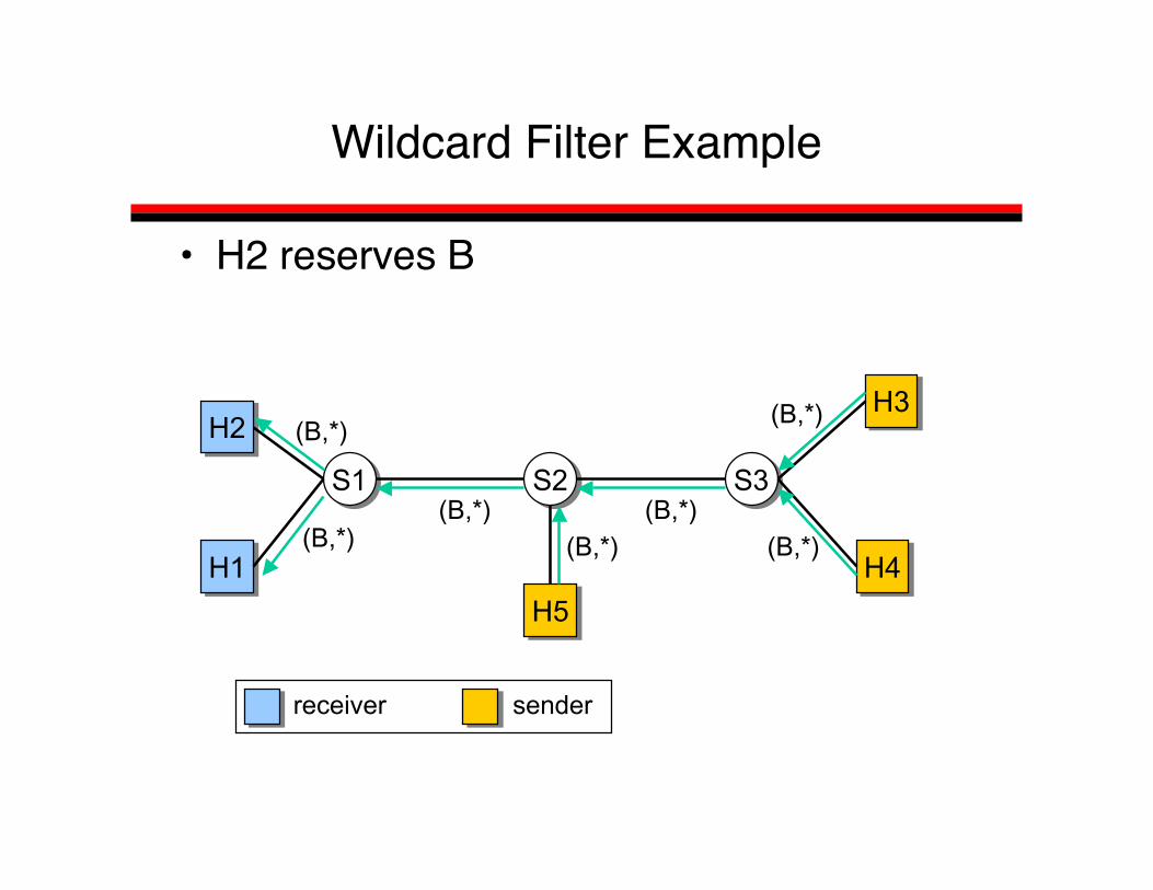
Wildcard Filter Example
• H2 reserves B
S1S1 S2S2 S3S3
H2H2
H1H1
H5H5
H4H4
H3H3
(B,*)(B,*) (B,*)
senderreceiver
(B,*)
(B,*) (B,*)
(B,*)

Wildcard Filter
• Advantages– Minimal state at routers
• Routers need to maintain only routing state augmentedby reserved bandwidth on outgoing links
• Disadvantages– May result in inefficient resource utilization
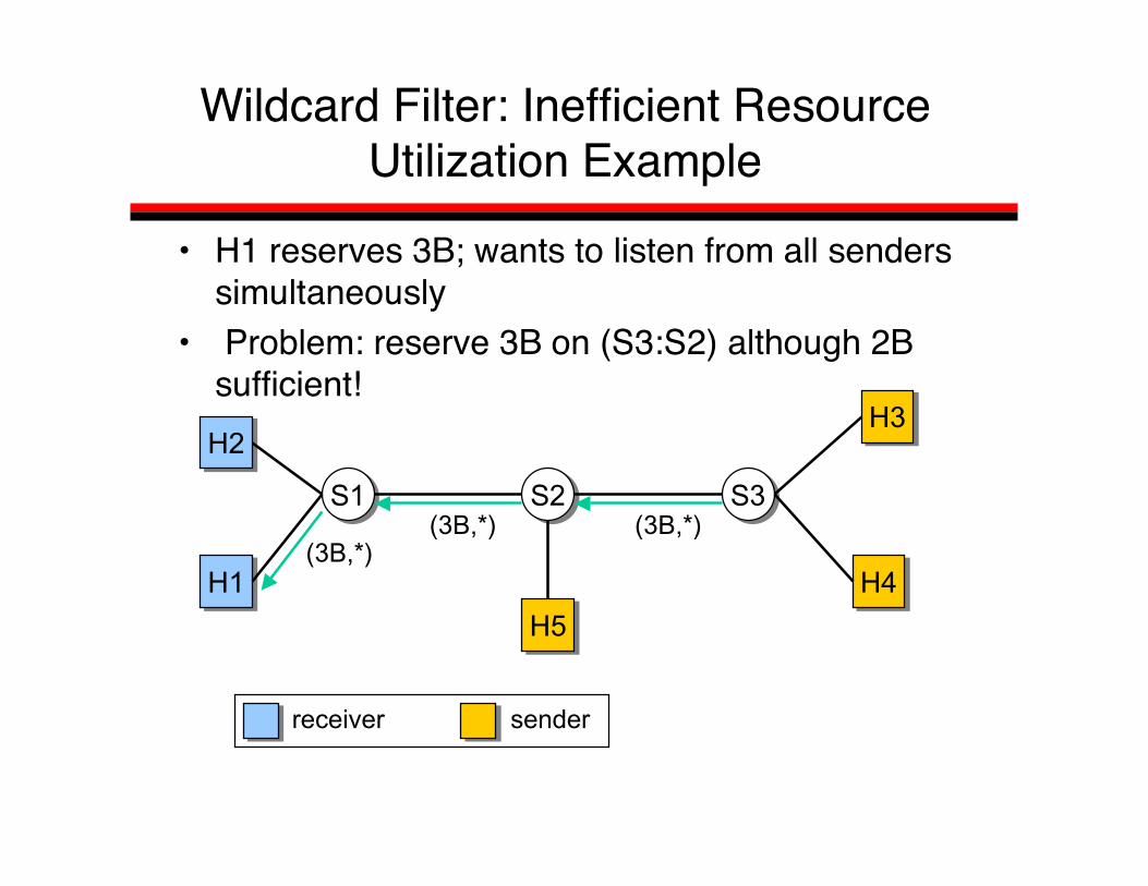
Wildcard Filter: Inefficient ResourceUtilization Example
• H1 reserves 3B; wants to listen from all senderssimultaneously
• Problem: reserve 3B on (S3:S2) although 2Bsufficient!
S1S1 S2S2 S3S3
H2H2
H1H1
H5H5
H4H4
H3H3
(3B,*)(3B,*) (3B,*)
senderreceiver
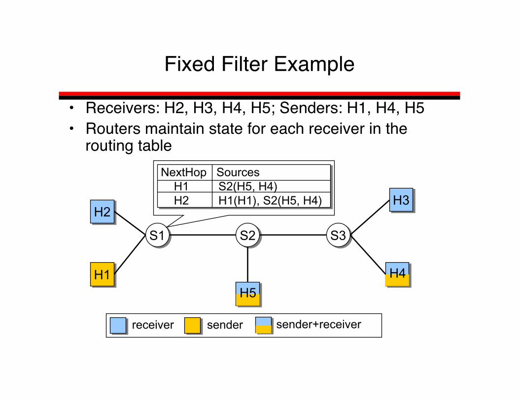
Fixed Filter Example
• Receivers: H2, H3, H4, H5; Senders: H1, H4, H5• Routers maintain state for each receiver in the
routing table
S1S1 S2S2 S3S3
H2H2
H1H1
H3H3
senderreceiver
H5
H4
sender+receiver
NextHop Sources H1 S2(H5, H4) H2 H1(H1), S2(H5, H4)

Fixed Filter Example
• H2 wants to receive B only from H4
S1S1 S2S2 S3S3
H2H2
H1H1
H3H3
senderreceiver
H5
H4
sender+receiver
(B,H4)
(B,H4) (B,H4)(B,H4)

Dynamic Filter Example
• H5 wants to receive 2B from any source
S1S1 S2S2 S3S3
H2H2
H1H1
H3H3
senderreceiver
H5
H4
sender+receiver
(B,H4) (B,H4)(B,H4)(2B,*)
(B,H4)(B,*)
(B,*)

Soft State
• Per session state has a timer associated with it– path state, reservation state
• State lost when timer expires• Sender/Receiver periodically refreshes the state• Claimed advantages
– no need to clean up dangling state after failure– can tolerate lost signaling packets
• signaling message need not be reliably transmitted– easy to adapt to route changes
• State can be explicitly deleted by a Teardownmessage
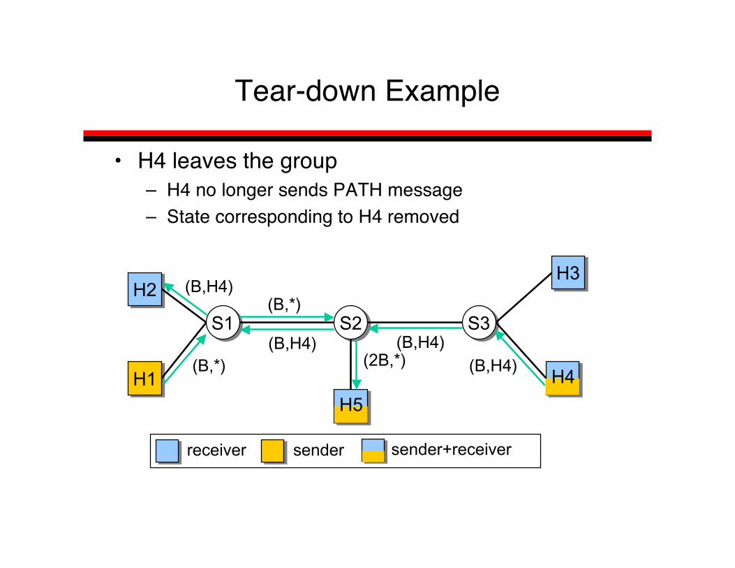
Tear-down Example
• H4 leaves the group– H4 no longer sends PATH message– State corresponding to H4 removed
S1S1 S2S2 S3S3
H2H2
H1H1
H3H3
senderreceiver
H5
H4
sender+receiver
(B,H4) (B,H4)(B,H4)(2B,*)
(B,H4)(B,*)
(B,*)

Tear-down Example
• H4 leaves the group– H4 no longer sends PATH message– State corresponding to H4 removed
S1S1 S2S2 S3S3
H2H2
H1H1
H3H3
senderreceiver
H5
sender+receiver
(2B,*)
(B,*)
(B,*)

RSVP Soft-state
• RSVP control messages need to be sentperiodically– State will disappear if not refreshed– Periodic state refresh every t sec (30 sec)– If no refresh within n*t (n=3) , delete state
• RSVP messages sent as router-alertmessage– Intermediate routers intercept packets and update
state accordingly

Soft State (cont)
• Per session state has a timer associated with it– Path state, reservation state
• State lost when timer expires• Sender/Receiver periodically refreshes the state,
resends PATH/RESV messages, resets timer• Claimed advantages
– No need to clean up dangling state after failure– Can tolerate lost signaling packets
• Signaling message need not be reliably transmitted– Easy to adapt to route changes
• State can be explicitly deleted by a Teardownmessage

RSVP and Routing
• RSVP designed to work with variety of routingprotocols
• Minimal routing service– RSVP asks routing how to route a PATH message
• Route pinning– addresses QoS changes due to “avoidable” route
changes while session in progress• QoS routing
– RSVP route selection based on QoS parameters– granularity of reservation and routing may differ
• Explicit routing– Use RSVP to set up routes for reserved traffic

Recap of RSVP
• PATH message– sender template and traffic spec– advertisement– mark route for RESV message– follow data path
• RESV message– reservation request, including flow and filter spec– reservation style and merging rules– follow reverse data path
• Other messages– PathTear, ResvTear, PathErr, ResvErr

Why did IntServ fail?
• Economic factors– Deployment cost vs Benefit
• Is reservation, the right approach?– Multicast centric view
• Is per-flow state maintenance an issue?• More about QoS in general …

What is the Problem?
• Goal: provide support for wide variety ofapplications:– Interactive TV, IP telephony, on-line gamming
(distributed simulations), VPNs, etc• Problem:
– Best-effort cannot do it?– Intserv can support all these applications, but
• Too complex• Not scalable

Differentiated Services (Diffserv)
• Build around the concept of domain• Domain – a contiguous region of network under
the same administrative ownership• Differentiate between edge and core routers• Edge routers
– Perform per aggregate shaping or policing– Mark packets with a small number of bits; each bit
encoding represents a class (subclass)• Core routers
– Process packets based on packet marking• Far more scalable than Intserv, but provides
weaker services
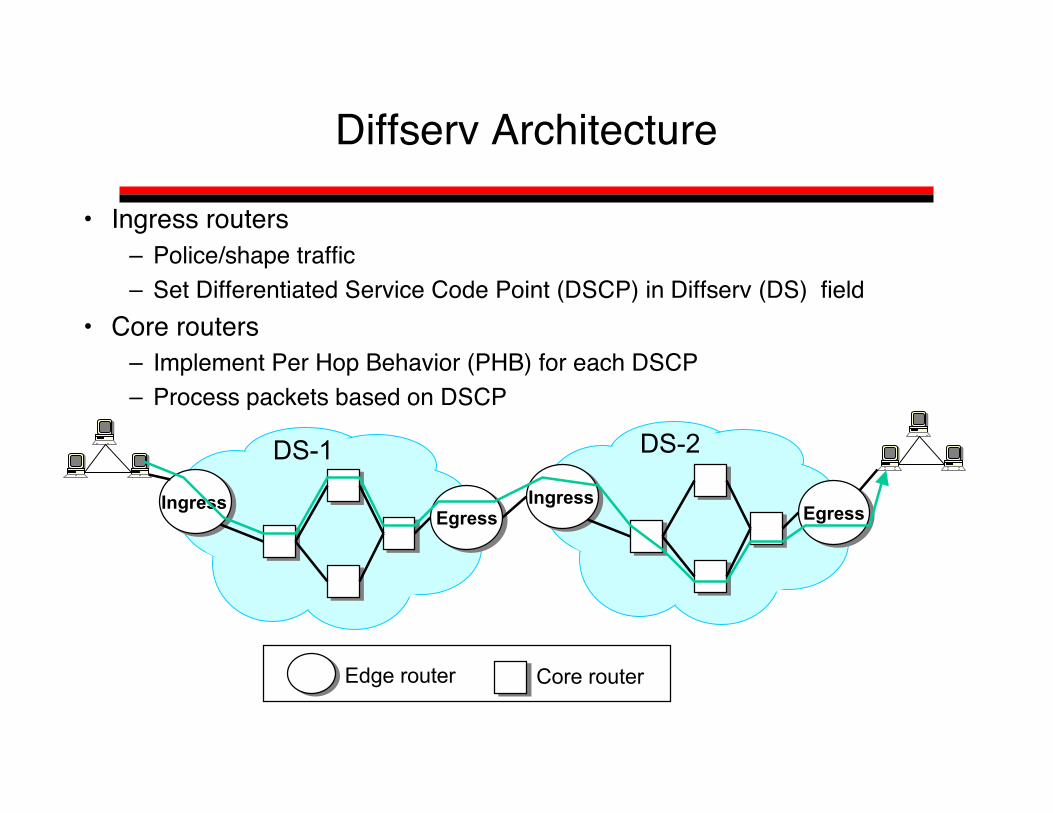
Diffserv Architecture
• Ingress routers– Police/shape traffic– Set Differentiated Service Code Point (DSCP) in Diffserv (DS) field
• Core routers– Implement Per Hop Behavior (PHB) for each DSCP– Process packets based on DSCP
IngressEgressEgress
IngressEgressEgress
DS-1 DS-2
Edge router Core router

Differentiated Service (DS) Field
Version HLen TOS Length
Identification Fragment offsetFlags
Source address
Destination address
TTL Protocol Header checksum
0 4 8 16 19 31
Data
IPheader
• DS filed reuse the first 6 bits from the former Type ofService (TOS) byte
• The other two bits are proposed to be used by ECN
DS Filed0 5 6 7

Differentiated Services
• Two types of service– Assured service– Premium service
• Plus, best-effort service

Assured Service[Clark & Wroclawski ‘97]
• Defined in terms of user profile, how much assuredtraffic is a user allowed to inject into the network
• Network: provides a lower loss rate than best-effort– In case of congestion best-effort packets are dropped first
• User: sends no more assured traffic than its profile– If it sends more, the excess traffic is converted to best-
effort

Assured Service
• Large spatial granularity service• Theoretically, user profile is defined
irrespective of destination– All other services we learnt are end-to-end,
i.e., we know destination(s) apriori• This makes service very useful, but hard
to provision (why ?)
Ingress
Traffic profile

Premium Service[Jacobson ’97]
• Provides the abstraction of a virtual pipebetween an ingress and an egress router
• Network: guarantees that premium packetsare not dropped and they experience lowdelay
• User: does not send more than the size ofthe pipe– If it sends more, excess traffic is delayed, and
dropped when buffer overflows
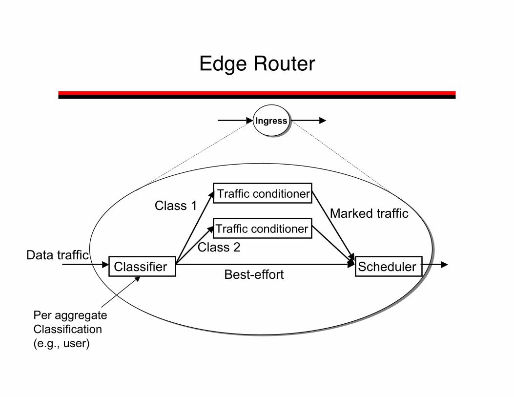
Edge Router
Classifier
Traffic conditioner
Traffic conditioner
Scheduler
Class 1
Class 2
Best-effort
Marked traffic
Ingress
Per aggregateClassification (e.g., user)
Data traffic

Assumptions
• Assume two bits– P-bit denotes premium traffic– A-bit denotes assured traffic
• Traffic conditioner (TC) implement– Metering– Marking– Shaping

TC Performing Metering/Marking
• Used to implement Assured Service• In-profile traffic is marked:
– A-bit is set in every packet• Out-of-profile (excess) traffic is unmarked
– A-bit is cleared (if it was previously set) in every packet; thistraffic treated as best-effort
r bps
b bits
Metering in-profile traffic
out-of-profile traffic
assured traffic
User profile (token bucket)
Set A-bit
Clear A-bit

TC Performing Metering/Marking/Shaping
• Used to implement Premium Service• In-profile traffic marked:
– Set P-bit in each packet• Out-of-profile traffic is delayed, and when buffer overflows it
is dropped
r bps
b bits
Metering/Shaper/Set P-bit
in-profile traffic
out-of-profile traffic(delayed and dropped)
premium traffic
User profile(token bucket)

Scheduler
• Employed by both edge and core routers• For premium service – use strict priority, or weighted fair queuing
(WFQ)• For assured service – use RIO (RED with In and Out)
– Always drop OUT packets first• For OUT measure entire queue• For IN measure only in-profile queue
OUT IN
Average queue length
1
Droppingprobability

Scheduler Example
• Premium traffic sent at high priority• Assured and best-effort traffic pass
through RIO and then sent at low priority
P-bit set?
A-bit set? RIO
yes
noyes
no
high priority
low priority
Control Path
• Each domain is assigned a Bandwidth Broker (BB)– Usually, used to perform ingress-egress bandwidth
allocation• BB is responsible to perform admission control in
the entire domain• BB not easy to implement
– Require complete knowledge about domain– Single point of failure, may be performance bottleneck– Designing BB still a research problem

Example
• Achieve end-to-end bandwidth guarantee
BBBB BBBB BBBB1
2 3
579
sender
receiver8 profile 6
profile4 profile

Comparison to Best-Effort and Intserv
Per flow setupLong term setupNo setupComplexity
End-to-endDomainEnd-to-endServicescope
Not scalable(each routermaintains perflow state)
Scalable(edge routersmaintains peraggregate state; corerouters per class state)
Highly scalable(nodesmaintain onlyrouting state)
Scalability
Per flow isolationPer flowguarantee
Per aggregateisolationPer aggregateguarantee
ConnectivityNo isolationNo guarantees
Service
IntservDiffservBest-Effort

Summary
• Diffserv more scalable than Intserv– Edge routers maintain per aggregate state– Core routers maintain state only for a few traffic classes
• But, provides weaker services than Intserv, e.g.,– Per aggregate bandwidth guarantees (premium service) vs.
per flow bandwidth and delay guarantees• BB is not an entirely solved problem
– Single point of failure– Handle only long term reservations (hours, days)

Building A QoS Router
• Is a high-bandwidth QoS capable router evenpossible?– Packets Per Second (PPS) the metric
• Real time operation– “No queuing before processing”
• Resource management– Link bandwidth– Buffer space

Real Time Operation
• Problem: Can queue packets while waiting to process– E.g.determine flow, output,– General packet classification problem (N-dimensional)– 5 dimensions, 512 rules, 1M PPS
• Head of line blocking problem• Solution:
– Aggressive router design• Multiprocessor, switched, shared forwarding engines• Similar to other higher performance routers
– Custom logic (ASIC, FPGA)
Resource Sharing

Resource Sharing

Non-technical Factors Impacting QoS
• Existing Networks– What is available today to solve our needs? Why
switch?• Business Models
– How QoS make doing business harders• Deployment Issues
– How QoS makes running the network harder.
Existing Networks
• Motivating applications?– Tele/Video conferencing, video distribution, virtual
circuits• IP+QoS must be better AND cheaper than:
– PSTN with N-way calling– Cable TV with digital recorders (Tivo)– Telecom leased lines (ISDN, ATM, sonet)– Peer to Peer networks
Business Issues
• Service provider offers premium service• Must be something customer can:
– Understand• Counterexample: Complex statistical reasoning
– Verify• 3rd party?• How do you know it works? Simulate a DoS attack?
– Reclaim loss if service is not delivered• If you buy a lock and it doesn’t work, do you try to get
your $ back? What if no one tried to break in?
Deployment Issues
• Today’s IP operators use simple models toreason about what is a “good network”
• Things you worry about:• IP packets• BGP routing• Simple Service Level Agreements (SLA)

Deployment Issues
• QoS introduces extra effort for operators:– shaping, policing, reservation signaling, per-reservation
billing and settlement.• QoS deployment changes:
– Interface between an ISP and its neighbors– adds whole new complexities for customer and support
personnel,– creates the need for accurate service auditing,
• Increases the risk of litigation• Tradeoff:
– Use QoS vs. make sure utilization is low most of the time?Which is easier?

Non-technical Issues summary
• Working on QoS for IP for 20 years?– Why little/no progress?
• QoS must be enough of a improvement toovercome all non-technical obstacles.– Value to users must exceed all costs– A typical technology adoption problem?
-> Technically better isn’t always good enough– QWERTY 10x backward compatibility rule?– QoS not cheaper, so 1000x?


