
CRV7 Semi-Automated Sealant Application
System Design
FINAL DESIGN REPORT
MECH 4860 – ENGINEERING DESIGN
Prepared By:
Sponsoring Company: Project Advisor:
Magellan Aerospace Dr. Igor Telichev, P. Eng,
Assistant Professor
Report Submitted: Monday, December 2nd
, 2013
TEAM 10
Avi Bahl ___________________
Michael Clendenan ___________________
Tyler Kabel ___________________
Conrad Kalita ___________________
Justin Reimer ___________________

Michael Clendenan
Perfect 10 Consulting
University of Manitoba
Winnipeg, MB
R3T 2N2
Paul Labossiere
Senior Instructor, P.Eng
University of Manitoba
Winnipeg, MB
R3T 2N2
December 2nd
, 2013
Dear Dr. Labossiere,
The attached report contains the design proposal for a semi-automated sealant system
to be considered by Magellan Aerospace Corporation to address its CRV7 manufacturing
process project request, as put forth September, 2013.
The report includes background information on Magellan Aerospace Corporation, the
existing manufacturing facilities, and specific details on the problem related to the CRV7
manufacturing process. Presentation of the client’s needs and objectives to be met by our
design are provided, as well as details pertaining to the final design concept selection.
The design selected is broken down and presented on an individual component basis to
highlight the distinct features each brings to the design as well as how it relates to the
client needs. The results and performance of the design are discussed through a risk
assessment (FMEA) and cost analysis. Moving forward, prototyping and testing may be
done as a result of this proposal for further analysis or procurement.
On behalf of Perfect 10 Consulting, I thank you for your time and consideration of
this design. Please feel free to contact us with any questions, concerns, or clarifications at
Sincerely,
Michael Clendenan
Perfect 10 Consulting - Team Leader
iii
Table of Contents
List of Figures............................................................................................................... v
List of Tables .............................................................................................................. vii
List of Acronyms ......................................................................................................... ix
Executive Summary ...................................................................................................... x
1. Introduction .......................................................................................................... 1
1.1. Problem Background .................................................................................... 2
1.1.1. Current Process ..................................................................................... 2
1.2. Problem Statement ........................................................................................ 3
1.3. Project Objectives ......................................................................................... 4
1.4. Technical Specifications ............................................................................... 5
1.4.1. Client Needs .......................................................................................... 5
1.4.2. Metrics ................................................................................................... 6
2. Final Concept Selection ..................................................................................... 10
3. Final Design ....................................................................................................... 12
3.1. Dispenser Design ........................................................................................ 15
3.2. Nozzle and Swivel Design .......................................................................... 17
3.3. Powertrain Design ...................................................................................... 18
3.3.1. Rotation Source ................................................................................... 19
3.3.2. Drivetrain ............................................................................................ 23
3.3.3. Bearings and Integration ..................................................................... 28
3.4. Applicator Body ......................................................................................... 31
3.4.1. Applicator Body Bottom Block ........................................................... 32
3.4.2. Applicator Body Top Block ................................................................ 33
3.4.3. Applicator Top Tube ........................................................................... 34
iv
3.4.4. Modular Functionality ......................................................................... 34
3.5. Support Structure Design ............................................................................ 36
3.5.1. Crane Selection ................................................................................... 37
3.5.2. Slide Rail Selection ............................................................................. 38
3.5.3. Suspension System Selection .............................................................. 39
3.6. System Control ........................................................................................... 40
4. Operations Manual ............................................................................................. 42
5. Cost Analysis ..................................................................................................... 45
5.1. Bill of Materials .......................................................................................... 45
5.2. Time Study ................................................................................................. 48
5.3. Lifespan and Maintenance Analysis ........................................................... 52
5.4. Economic Feasibility .................................................................................. 54
6. Failure Mode and Effects Analysis (FMEA) ..................................................... 58
7. Target Specifications Analysis........................................................................... 63
8. Recommendations .............................................................................................. 65
9. Conclusion ......................................................................................................... 66
10. Works Cited ....................................................................................................... 68
Appendix A ................................................................................................................ 71
Appendix B ............................................................................................................... 104
Appendix C ............................................................................................................... 121
Appendix D .............................................................................................................. 132

v
List of Figures
Figure 1: Display model of CRV7-C-15 motor showing exposed internal components. ... 1
Figure 2: Nozzle cross section showing sealant bead location. .......................................... 2
Figure 3: Rocket transportation cart with single CRV7 rocket. .......................................... 2
Figure 4: Sealant applicator machine currently used by Magellan Aerospace. .................. 3
Figure 5: Width comparison of circular track and rotating nozzle designs. ..................... 11
Figure 6: Semi-automated pneumatic powered grease sealant applicator assembly. ....... 12
Figure 7: Section view of grease sealant applicator sub-assembly. .................................. 13
Figure 8: Suspension system for grease sealant applicator. .............................................. 14
Figure 9: Image and section view of the VMS400 Mini Spool Valve. ............................. 16
Figure 10: Nozzle and swivel attached to the dispensing unit. ......................................... 18
Figure 11: Exploded view of nozzle and swivel. .............................................................. 18
Figure 12: Typical pneumatic motor . .............................................................................. 19
Figure 13: Typical pneumatic actuator. ............................................................................ 19
Figure 14: Dimensions and features for MMR-5001 selected motor. .............................. 23
Figure 15: Minimum spacing distance between dispenser and motor that gears must
satisfy. .............................................................................................................................. 24
Figure 16: Maximum spacing distance between dispenser and motor that gears must
satisfy. .............................................................................................................................. 24
Figure 17: Driving helical gear from motor engaged with nozzle swivel driven helical
gear. .................................................................................................................................. 27
Figure 18: Graph of motor torque vs. speed for various operating pressures. .................. 28
Figure 19: Intermediated shaft with major dimensions in inches. .................................... 29
Figure 20: Intermediate shaft assembled with drivetrain and rotation system. ................. 30
Figure 21: Tapered roller bearing location in powertrain assembly. ................................ 31
Figure 22: Applicator body assembly used to house dispenser and air motor
mechanisms. ..................................................................................................................... 32
Figure 23: Applicator body bottom block used to index CRV7 rockets. .......................... 33
Figure 24: Applicator body top block used to secure and protect the dispenser, swivel,
and drivetrain. ................................................................................................................... 33
vi
Figure 25: Applicator body tube used to protect the dispenser and motor from direct
damage and connect to the tool balancer cable................................................................. 34
Figure 26: Dual module configuration. ............................................................................ 35
Figure 27: Dual applicator module configuration exploded view. ................................... 35
Figure 28: TSJ50-FS-50-8-8 Free Standing Jib Crane. .................................................... 38
Figure 29: Tool trolley with arched saddle. ...................................................................... 39
Figure 30: Image and cut away view of the Endo XA-EW-3 Spring Balancer. ............... 40
Figure 31: DC-4 Silicone Sealant Container .................................................................... 42
Figure 32: Inspection of motor aft end ............................................................................. 43
Figure 33: Completed cart under covering ....................................................................... 44
vii
List of Tables
TABLE I: OBJECTIVES FOR SATISFYING CLIENT NEEDS...................................... 4
TABLE II: CLIENT NEEDS ............................................................................................. 5
TABLE III: METRICS AND UNITS................................................................................. 7
TABLE IV: TARGET SPECIFICATIONS ........................................................................ 8
TABLE V: PRELIMINARY COST ANALYSIS ............................................................ 10
TABLE VI: DISPENSER SELECTION CRITERIA ....................................................... 15
TABLE VII: PNEUMATIC ROTARY ACTUATOR CONSTRAINTS ......................... 20
TABLE VIII: PNEUMATIC MOTOR CONSTRAINTS ................................................ 21
TABLE IX: MANUFACTURER FEASIBILITY ............................................................ 22
TABLE X: POTENTIAL MCMASTER CARR PNEUMATIC MOTORS .................... 22
TABLE XI: CHOSEN GEAR CHARACTERISTICS ..................................................... 25
TABLE XII: BENDING AND PITTING STRESS SUMMARY .................................... 26
TABLE XIII: BEARING SELECTED ............................................................................. 31
TABLE XIV: SELECTION CRITERIA FOR THE SUPPORT STRUCTURE .............. 36
TABLE XV: SEALANT APPLICATOR COMPONENTS AND CORRESPONDING
WEIGHT. ......................................................................................................................... 37
TABLE XVI: CONTROL SYSTEM EQUIPMENT LIST .............................................. 41
TABLE XVII: BILL OF MATERIALS FOR THE SEALANT APPLICATION
SYSTEM .......................................................................................................................... 45
TABLE XVIII: TIME STUDY FOR THE ROTATING NOZZLE SEALANT
APPLICATOR SYSTEM DESIGN ................................................................................. 49
TABLE XIX: TIME STUDY FOR MAGELLAN'S CURRENT SEALANT
APPLICATOR SYSTEM ................................................................................................. 50
TABLE XX: TIME STUDY FOR THE ROTATING NOZZLE SEALANT
APPLICATOR SYSTEM DESIGN WITH TWO APPLICATORS ................................ 51
TABLE XXI: MAINTENACE COSTS OF DESIGN IN OPERATION ......................... 53
TABLE XXII: CONSTANTS FROM ECONOMIC ANALYSIS FOR SINGLE
APPLICATOR ................................................................................................................. 54
TABLE XXIII: ECONOMIC ANALYSIS RESULTS FOR A SINGLE
APPLICATOR ................................................................................................................. 55
viii
TABLE XXIV: CONSTANTS FROM ECONOMIC ANALYSIS FOR DUAL
APPLICATOR ................................................................................................................. 56
TABLE XXV: ECONOMIC ANALYSIS RESULTS FOR A DUAL APPLICATOR ... 56
TABLE XXVI: FMEA ANALYSIS ON THE COMPONENTS OF THE DESIGN ....... 59
TABLE XXVII: FMEA ANALYSIS OF THE PROCESSES USING THE DESIGN .... 61
TABLE XXVIII: PROPOSED DESIGN SPECIFICATIONS ......................................... 63
ix
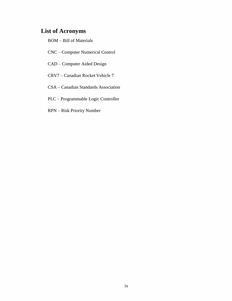
List of Acronyms
BOM – Bill of Materials
CNC – Computer Numerical Control
CAD – Computer Aided Design
CRV7 – Canadian Rocket Vehicle 7
CSA – Canadian Standards Association
PLC – Programmable Logic Controller
RPN – Risk Priority Number
x
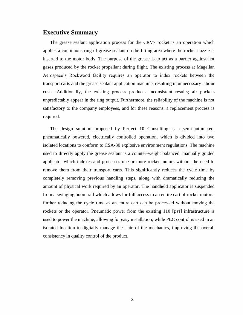
Executive Summary
The grease sealant application process for the CRV7 rocket is an operation which
applies a continuous ring of grease sealant on the fitting area where the rocket nozzle is
inserted to the motor body. The purpose of the grease is to act as a barrier against hot
gases produced by the rocket propellant during flight. The existing process at Magellan
Aerospace’s Rockwood facility requires an operator to index rockets between the
transport carts and the grease sealant application machine, resulting in unnecessary labour
costs. Additionally, the existing process produces inconsistent results; air pockets
unpredictably appear in the ring output. Furthermore, the reliability of the machine is not
satisfactory to the company employees, and for these reasons, a replacement process is
required.
The design solution proposed by Perfect 10 Consulting is a semi-automated,
pneumatically powered, electrically controlled operation, which is divided into two
isolated locations to conform to CSA-30 explosive environment regulations. The machine
used to directly apply the grease sealant is a counter-weight balanced, manually guided
applicator which indexes and processes one or more rocket motors without the need to
remove them from their transport carts. This significantly reduces the cycle time by
completely removing previous handling steps, along with dramatically reducing the
amount of physical work required by an operator. The handheld applicator is suspended
from a swinging boom rail which allows for full access to an entire cart of rocket motors,
further reducing the cycle time as an entire cart can be processed without moving the
rockets or the operator. Pneumatic power from the existing 110 [ ] infrastructure is
used to power the machine, allowing for easy installation, while PLC control is used in an
isolated location to digitally manage the state of the mechanics, improving the overall
consistency in quality control of the product.
xi
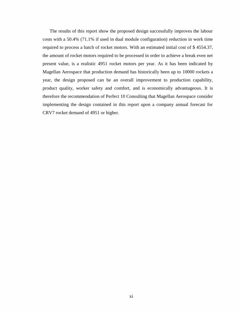
The results of this report show the proposed design successfully improves the labour
costs with a 50.4% (71.1% if used in dual module configuration) reduction in work time
required to process a batch of rocket motors. With an estimated initial cost of $ 4554.37,
the amount of rocket motors required to be processed in order to achieve a break even net
present value, is a realistic 4951 rocket motors per year. As it has been indicated by
Magellan Aerospace that production demand has historically been up to 10000 rockets a
year, the design proposed can be an overall improvement to production capability,
product quality, worker safety and comfort, and is economically advantageous. It is
therefore the recommendation of Perfect 10 Consulting that Magellan Aerospace consider
implementing the design contained in this report upon a company annual forecast for
CRV7 rocket demand of 4951 or higher.
1 | Page
1. Introduction
Perfect 10 Consulting has been tasked with the design of a new sealant application
system for use in the assembly process of the CRV7 (Canadian Rocket Vehicle 7) rocket.
The CRV7 is a 2.75 [ ] diameter unguided rocket system developed and manufactured
by Magellan Aerospace Corporation and produced in Magellan’s Rockwood Propellant
Plant just north of Winnipeg, MB.
Magellan Aerospace Corporation is a Canadian based manufacturer of aerospace
systems and components. Some of its products include aero engines, aero structures,
rockets, and satellites. Over 800,000 CRV7 rockets have been produced for thirteen
nations globally, and have been considered a standard for air-to-ground weaponry since
early 1970. [1]
The CRV7 has two variants: the C-15 and C-17. The C-15 is designed for fixed-wing
aircraft, whereas the C-17 is optimized for use in helicopter applications [1]. Both
variants are produced at the Rockwood Propellant Plant, and therefore both are taken into
account in this project.
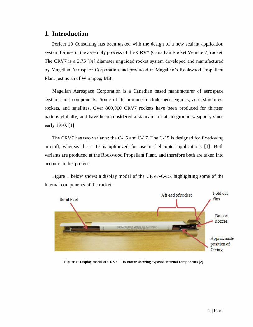
Figure 1 below shows a display model of the CRV7-C-15, highlighting some of the
internal components of the rocket.
Figure 1: Display model of CRV7-C-15 motor showing exposed internal components [2].
2 | Page
1.1. Problem Background
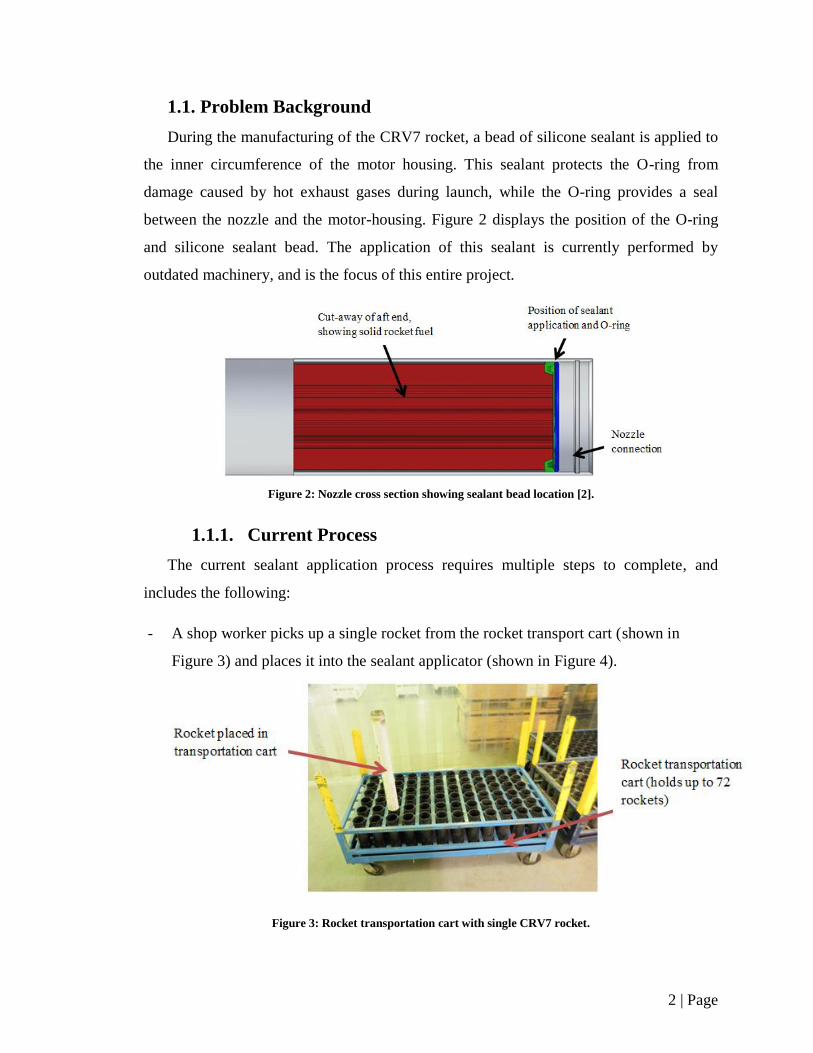
During the manufacturing of the CRV7 rocket, a bead of silicone sealant is applied to
the inner circumference of the motor housing. This sealant protects the O-ring from
damage caused by hot exhaust gases during launch, while the O-ring provides a seal
between the nozzle and the motor-housing. Figure 2 displays the position of the O-ring
and silicone sealant bead. The application of this sealant is currently performed by
outdated machinery, and is the focus of this entire project.
Figure 2: Nozzle cross section showing sealant bead location [2].
1.1.1. Current Process
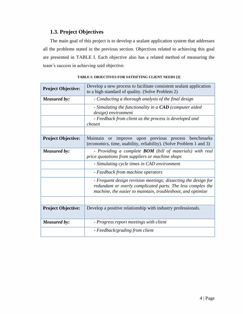
The current sealant application process requires multiple steps to complete, and
includes the following:
- A shop worker picks up a single rocket from the rocket transport cart (shown in
Figure 3) and places it into the sealant applicator (shown in Figure 4).
Figure 3: Rocket transportation cart with single CRV7 rocket.

3 | Page
- The applicator applies a bead of sealant to the inner circumference of the motor
housing.
Figure 4: Sealant applicator machine currently used by Magellan Aerospace.
- The shop worker then takes the rocket and places it into another transportation cart to
prepare for the next manufacturing process.
1.2. Problem Statement
The sealant application process has three main problems, each of which was taken
into account during the project:
1. The current process requires excessive physical handling and work from the shop
worker, since the 10 [ ] rockets are repetitively lifted and lowered until the batch
is completed.
2. The current applicator is unreliable and does not produce consistent results.
3. The current process can complete only one rocket at a time, potentially limiting
the production rate
4 | Page
1.3. Project Objectives
The main goal of this project is to develop a sealant application system that addresses
all the problems stated in the previous section. Objectives related to achieving this goal
are presented in TABLE I. Each objective also has a related method of measuring the
team’s success in achieving said objective.
TABLE I: OBJECTIVES FOR SATISFYING CLIENT NEEDS [3]
Project Objective: Develop a new process to facilitate consistent sealant application
to a high standard of quality. (Solve Problem 2)
Measured by: - Conducting a thorough analysis of the final design
- Simulating the functionality in a CAD (computer aided
design) environment
- Feedback from client as the process is developed and
chosen
Project Objective: Maintain or improve upon previous process benchmarks
(economics, time, usability, reliability). (Solve Problem 1 and 3)
Measured by: - Providing a complete BOM (bill of materials) with real
price quotations from suppliers or machine shops
- Simulating cycle times in CAD environment
- Feedback from machine operators
- Frequent design revision meetings; dissecting the design for
redundant or overly complicated parts. The less complex the
machine, the easier to maintain, troubleshoot, and optimize
Project Objective: Develop a positive relationship with industry professionals.
Measured by: - Progress report meetings with client
- Feedback/grading from client
5 | Page
1.4. Technical Specifications
The technical specifications taken into account during the final design phase were
attained by analyzing the client needs as obtained through direct interviews [4].
Corresponding metrics were then attributed to each need to measure its attainability.
1.4.1. Client Needs
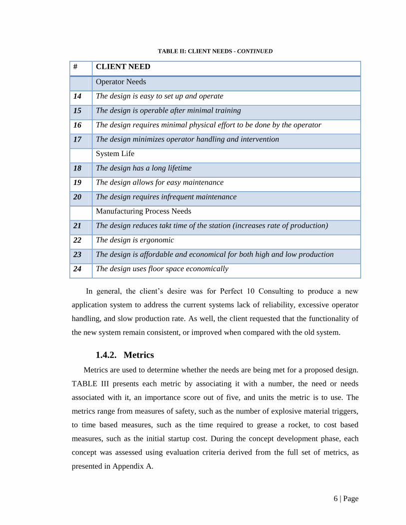
TABLE II details the client’s needs in terms of safety features, greasing
functionality, general design functionality, operator needs, system life, and the
manufacturing process respectively.
TABLE II: CLIENT NEEDS [3]
# CLIENT NEED
Safety Features
1 The design is safe to operate
2 The design produces a level of sound safe for human interaction
3 The design is capable of safely functioning in an explosives environment
Design Greasing Functionality
4 The design applies sealant to the motor nozzle junction
5 The design has a grease output that is regulated and verifiable
6 The design applies sealant to a batch rockets before refilling of sealant is
required
7 The design can dispense the silicone sealant used for CRV7 rockets
8 The design consistently produces the correct bead size and spacing of sealant
9 The design produces no air pockets in the applied sealant
General Design Functionality
10 The design is capable of accommodating people of varying heights
11 The design operates regularly for extended periods of time with consistent quality
results
12 The design does not damage the rocket
13 The design is capable of interfacing with the C-17 and C-15 rocket motors
6 | Page
TABLE II: CLIENT NEEDS - CONTINUED
# CLIENT NEED
Operator Needs
14 The design is easy to set up and operate
15 The design is operable after minimal training
16 The design requires minimal physical effort to be done by the operator
17 The design minimizes operator handling and intervention
System Life
18 The design has a long lifetime
19 The design allows for easy maintenance
20 The design requires infrequent maintenance
Manufacturing Process Needs
21 The design reduces takt time of the station (increases rate of production)
22 The design is ergonomic
23 The design is affordable and economical for both high and low production
24 The design uses floor space economically
In general, the client’s desire was for Perfect 10 Consulting to produce a new
application system to address the current systems lack of reliability, excessive operator
handling, and slow production rate. As well, the client requested that the functionality of
the new system remain consistent, or improved when compared with the old system.
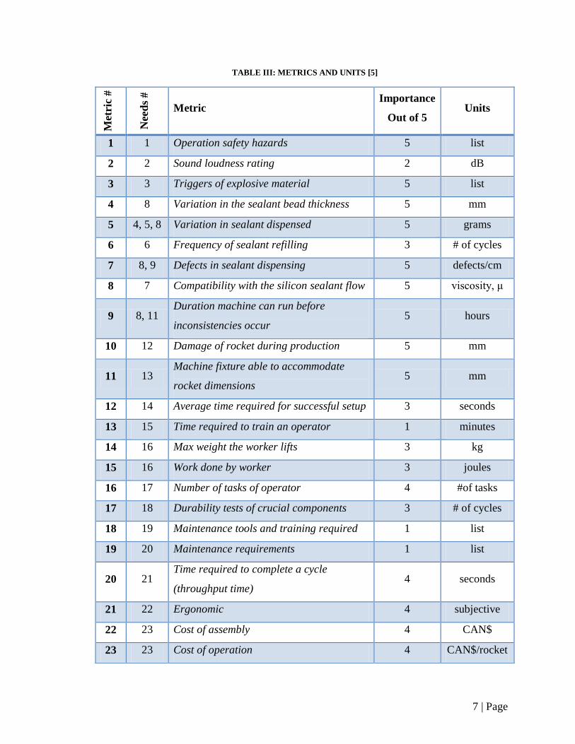
1.4.2. Metrics
Metrics are used to determine whether the needs are being met for a proposed design.
TABLE III presents each metric by associating it with a number, the need or needs
associated with it, an importance score out of five, and units the metric is to use. The
metrics range from measures of safety, such as the number of explosive material triggers,
to time based measures, such as the time required to grease a rocket, to cost based
measures, such as the initial startup cost. During the concept development phase, each
concept was assessed using evaluation criteria derived from the full set of metrics, as
presented in Appendix A.
7 | Page
TABLE III: METRICS AND UNITS [5]
Met
ric
#
Nee
ds
#
Metric Importance
Out of 5 Units
1 1 Operation safety hazards 5 list
2 2 Sound loudness rating 2 dB
3 3 Triggers of explosive material 5 list
4 8 Variation in the sealant bead thickness 5 mm
5 4, 5, 8 Variation in sealant dispensed 5 grams
6 6 Frequency of sealant refilling 3 # of cycles
7 8, 9 Defects in sealant dispensing 5 defects/cm
8 7 Compatibility with the silicon sealant flow 5 viscosity, μ
9 8, 11 Duration machine can run before
inconsistencies occur 5 hours
10 12 Damage of rocket during production 5 mm
11 13 Machine fixture able to accommodate
rocket dimensions 5 mm
12 14 Average time required for successful setup 3 seconds
13 15 Time required to train an operator 1 minutes
14 16 Max weight the worker lifts 3 kg
15 16 Work done by worker 3 joules
16 17 Number of tasks of operator 4 #of tasks
17 18 Durability tests of crucial components 3 # of cycles
18 19 Maintenance tools and training required 1 list
19 20 Maintenance requirements 1 list
20 21 Time required to complete a cycle
(throughput time) 4 seconds
21 22 Ergonomic 4 subjective
22 23 Cost of assembly 4 CAN$
23 23 Cost of operation 4 CAN$/rocket
8 | Page
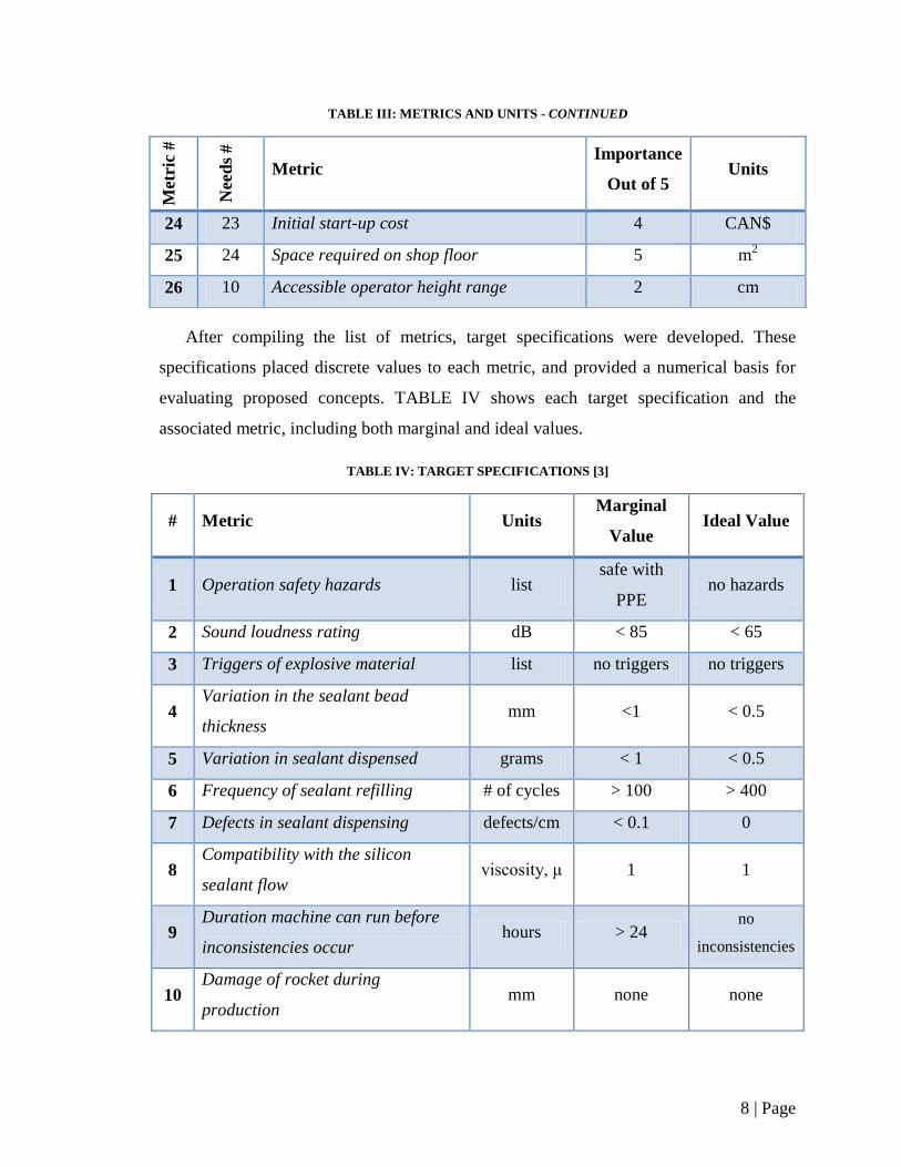
TABLE III: METRICS AND UNITS - CONTINUED
After compiling the list of metrics, target specifications were developed. These
specifications placed discrete values to each metric, and provided a numerical basis for
evaluating proposed concepts. TABLE IV shows each target specification and the
associated metric, including both marginal and ideal values.
TABLE IV: TARGET SPECIFICATIONS [3]
# Metric Units Marginal
Value Ideal Value
1 Operation safety hazards list safe with
PPE no hazards
2 Sound loudness rating dB < 85 < 65
3 Triggers of explosive material list no triggers no triggers
4 Variation in the sealant bead
thickness mm <1 < 0.5
5 Variation in sealant dispensed grams < 1 < 0.5
6 Frequency of sealant refilling # of cycles > 100 > 400
7 Defects in sealant dispensing defects/cm < 0.1 0
8 Compatibility with the silicon
sealant flow viscosity, μ 1 1
9 Duration machine can run before
inconsistencies occur hours > 24
no
inconsistencies
10 Damage of rocket during
production mm none none
Met
ric
#
Nee
ds
#
Metric Importance
Out of 5 Units
24 23 Initial start-up cost 4 CAN$
25 24 Space required on shop floor 5 m2
26 10 Accessible operator height range 2 cm
9 | Page
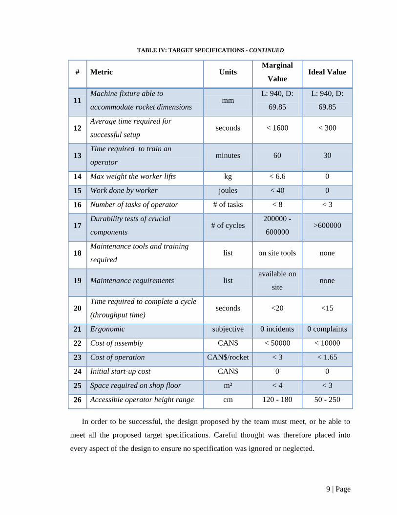
TABLE IV: TARGET SPECIFICATIONS - CONTINUED
# Metric Units Marginal
Value Ideal Value
11 Machine fixture able to
accommodate rocket dimensions mm
L: 940, D:
69.85
L: 940, D:
69.85
12 Average time required for
successful setup seconds < 1600 < 300
13 Time required to train an
operator minutes 60 30
14 Max weight the worker lifts kg < 6.6 0
15 Work done by worker joules < 40 0
16 Number of tasks of operator # of tasks < 8 < 3
17 Durability tests of crucial
components # of cycles
200000 -
600000 >600000
18 Maintenance tools and training
required list on site tools none
19 Maintenance requirements list available on
site none
20 Time required to complete a cycle
(throughput time) seconds <20 <15
21 Ergonomic subjective 0 incidents 0 complaints
22 Cost of assembly CAN$ < 50000 < 10000
23 Cost of operation CAN$/rocket < 3 < 1.65
24 Initial start-up cost CAN$ 0 0
25 Space required on shop floor m² < 4 < 3
26 Accessible operator height range cm 120 - 180 50 - 250
In order to be successful, the design proposed by the team must meet, or be able to
meet all the proposed target specifications. Careful thought was therefore placed into
every aspect of the design to ensure no specification was ignored or neglected.
10 | Page
2. Final Concept Selection
Following detailed brainstorming on new greasing solutions, three final conceptual
solutions for the application of sealant were considered: 2.5 CNC (Computer Numerical
Controlled), rotating nozzle, and circular track. The 2.5 CNC concept incorporated a
suspended X&Y table with a grease dispensing gear pump. The machine would be
preprogrammed to check each rocket location in a cart for the presence of a rocket, and
then grease accordingly. On the other hand, the rotating nozzle concept included a
pneumatically powered, rotating dispensing head suspended from a tool balancer,
manually positioned by an operator from rocket to rocket. Finally, the circular track
concept incorporated an angled nozzle on a large circular bearing, which would rotate via
a pneumatic motor. A torque reaction arm would support the entire greasing apparatus,
and is easily positioned by an operator. Further details of the selection and preliminary
development of these three concepts can be found in Appendix A.
After discussion with the client, the support assemblies of both the circular track and
rotating nozzle designs were noted as being interchangeable. As such, both support styles
would be considered in either design.
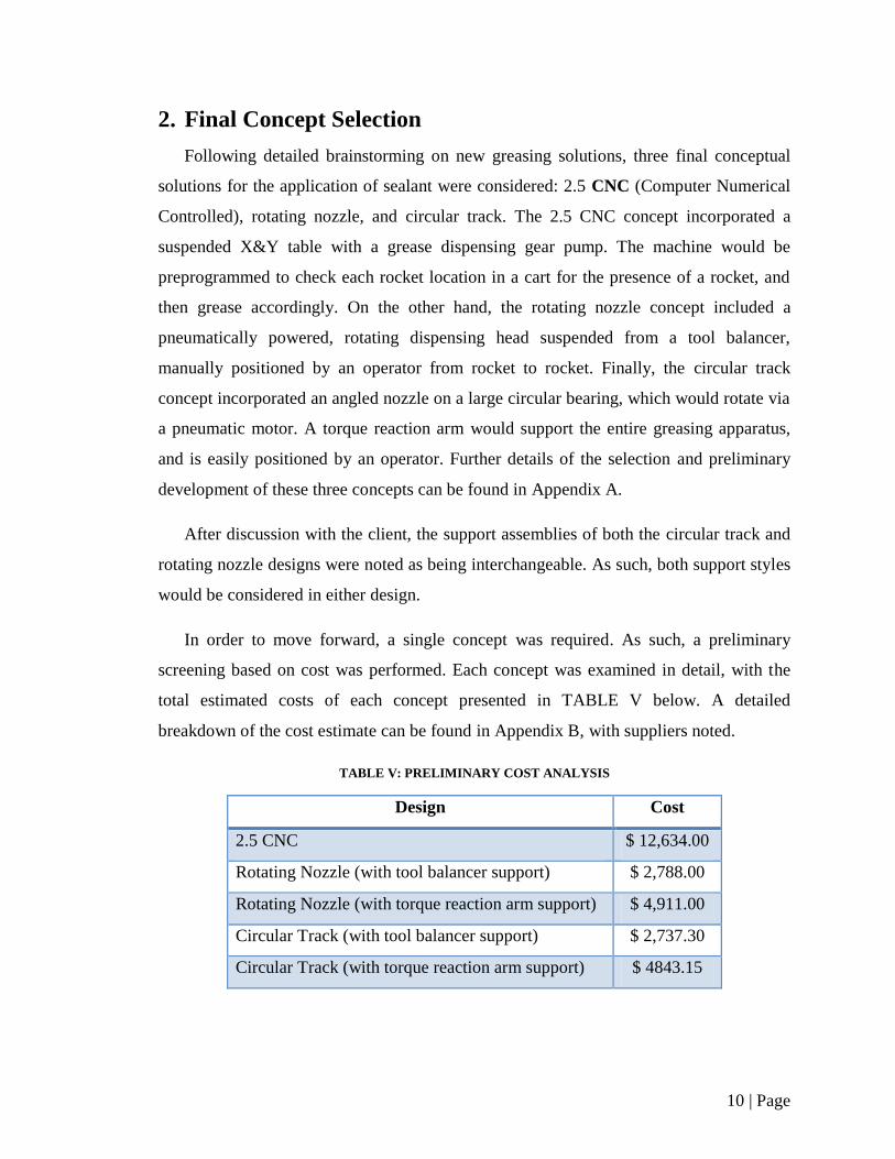
In order to move forward, a single concept was required. As such, a preliminary
screening based on cost was performed. Each concept was examined in detail, with the
total estimated costs of each concept presented in TABLE V below. A detailed
breakdown of the cost estimate can be found in Appendix B, with suppliers noted.
TABLE V: PRELIMINARY COST ANALYSIS
Design Cost
2.5 CNC $ 12,634.00
Rotating Nozzle (with tool balancer support) $ 2,788.00
Rotating Nozzle (with torque reaction arm support) $ 4,911.00
Circular Track (with tool balancer support) $ 2,737.30
Circular Track (with torque reaction arm support) $ 4843.15
11 | Page
The high cost of the 2.5 CNC concept, as well additional complexity exposed by the
thorough cost evaluation led to its elimination from future consideration. As well, torque
reaction arms were eliminated based upon their high cost and added complexity. Only the
rotating nozzle and circular track concepts, both with tool balancer supports, remained.
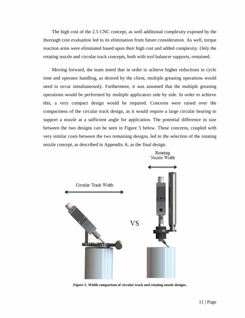
Moving forward, the team noted that in order to achieve higher reductions in cycle
time and operator handling, as desired by the client, multiple greasing operations would
need to occur simultaneously. Furthermore, it was assumed that the multiple greasing
operations would be performed by multiple applicators side by side. In order to achieve
this, a very compact design would be required. Concerns were raised over the
compactness of the circular track design, as it would require a large circular bearing to
support a nozzle at a sufficient angle for application. The potential difference in size
between the two designs can be seen in Figure 5 below. These concerns, coupled with
very similar costs between the two remaining designs, led to the selection of the rotating
nozzle concept, as described in Appendix A, as the final design.
Figure 5: Width comparison of circular track and rotating nozzle designs.
12 | Page
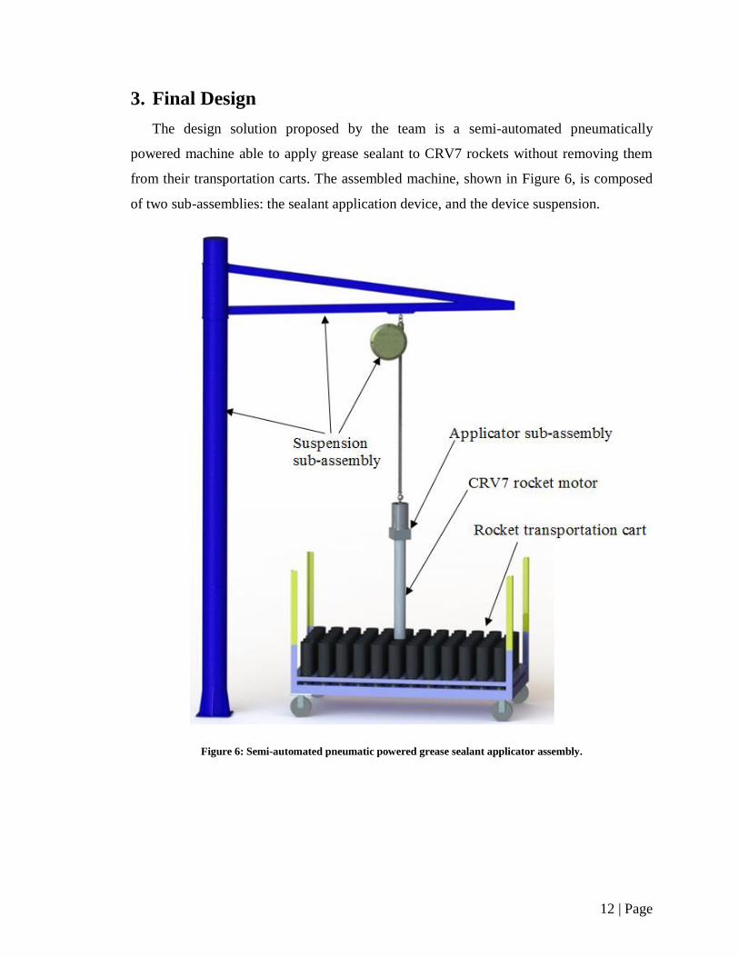
3. Final Design
The design solution proposed by the team is a semi-automated pneumatically
powered machine able to apply grease sealant to CRV7 rockets without removing them
from their transportation carts. The assembled machine, shown in Figure 6, is composed
of two sub-assemblies: the sealant application device, and the device suspension.
Figure 6: Semi-automated pneumatic powered grease sealant applicator assembly.
13 | Page
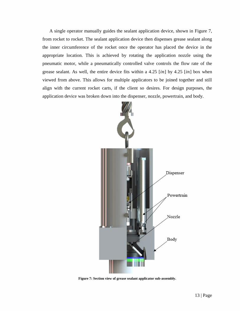
A single operator manually guides the sealant application device, shown in Figure 7,
from rocket to rocket. The sealant application device then dispenses grease sealant along
the inner circumference of the rocket once the operator has placed the device in the
appropriate location. This is achieved by rotating the application nozzle using the
pneumatic motor, while a pneumatically controlled valve controls the flow rate of the
grease sealant. As well, the entire device fits within a 4.25 [ ] by 4.25 [ ] box when
viewed from above. This allows for multiple applicators to be joined together and still
align with the current rocket carts, if the client so desires. For design purposes, the
application device was broken down into the dispenser, nozzle, powertrain, and body.
Figure 7: Section view of grease sealant applicator sub-assembly.
14 | Page
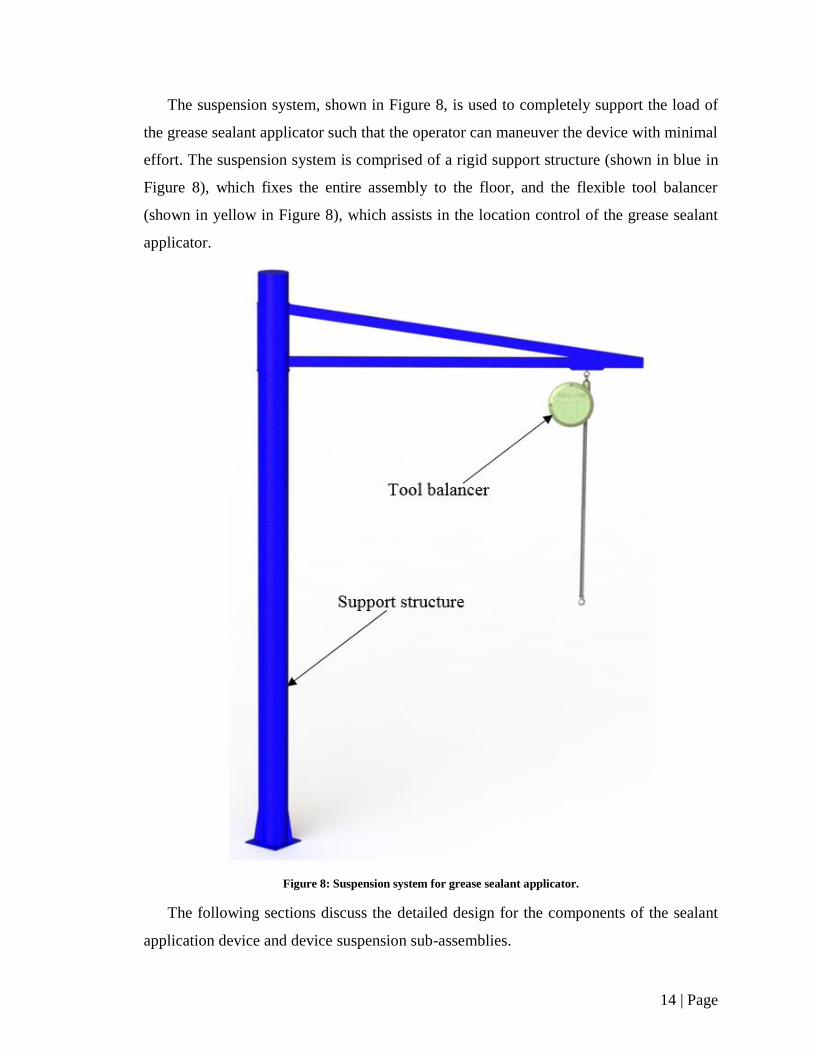
The suspension system, shown in Figure 8, is used to completely support the load of
the grease sealant applicator such that the operator can maneuver the device with minimal
effort. The suspension system is comprised of a rigid support structure (shown in blue in
Figure 8), which fixes the entire assembly to the floor, and the flexible tool balancer
(shown in yellow in Figure 8), which assists in the location control of the grease sealant
applicator.
Figure 8: Suspension system for grease sealant applicator.
The following sections discuss the detailed design for the components of the sealant
application device and device suspension sub-assemblies.

15 | Page
3.1. Dispenser Design
The dispensing system is a crucial component of the sealant applicator and is
responsible for dispensing a metered amount of sealant, as well as starting or stopping the
sealant supply to the nozzle. Although the nozzle rotates 360º to apply sealant to the
rocket, the dispenser is in fact stationary within the applicator assembly. To find a
suitable dispenser, a group of selection criteria was established and used to evaluate
current products available in order to make a final selection.
To be considered a feasible choice, the dispenser must meet all the selection criteria
listed in TABLE VI.
TABLE VI: DISPENSER SELECTION CRITERIA
Criteria Description
Explosion Proof The dispenser must comply with CSA-30
(Canadian Standards Association) standards.
Minimal Cost The dispenser with the lowest cost will be
preferred.
Operating Air Pressure The operating air pressure must be lower than
available airline pressure (110 [ ]).
Minimal Mass and Size The dispenser with the lowest mass and size
will be preferred.
Controllable Flow Rate The dispenser must be capable of regulating
the flow rate of the sealant.
Compatibility with Existing Sealant The dispenser must be able to dispense a
continuous bead of the existing sealant.
The selection criteria listed in TABLE VI represents the minimum requirements for
the dispenser selection with equal weightage. However, if multiple dispensers meet all
the criteria, minimal cost will be the deciding criterion.
Research was conducted to find dispensers that satisfied the selection criteria. The
two main categories of dispensers are gear pumps and dispensing valves. However, gear
16 | Page
pumps are only available for large scale applications, and therefore the majority of the
research was conducted on dispensing valves. Dispensing valves are available in a
number of different configurations, including diaphragm valves, positive-displacement
valves, spray valves, poppet valves, cartridge valves, needle-mini valves, pinch tube
valves and spool valves [6]. Each configuration is suitable for a certain type of
application. Diaphragm, positive-displacement, poppet, and spray valves are
recommended for dispensing shots of fluid, and are therefore not suitable for dispensing a
continuous bead of sealant [6]. Needle-mini and cartridge valves are recommended for
micro scale applications. Pinch tube valves are not capable of dispensing high viscosity
fluids such as the sealant currently used [7]. Spool valves are most suited for the sealant
applicator as they can dispense a continuous bead of high viscosity fluid.
The team evaluated a variety of dispensing valves offered by different manufacturers.
After evaluating the valves with the selection criteria in TABLE VI, the VMS400 Mini
Spool Valve from Fisnar Inc. was chosen as it satisfies all the requirements, including
minimal cost. Figure 9 shows an image of VMS400 Mini Spool Valve with a section
view that highlights major components of the valve.
Figure 9: Image and section view of the VMS400 Mini Spool Valve [8].
17 | Page
The VMS400 is capable of dispensing high viscosity fluids with a suck-back effect
that eliminates lumping at the end of the nozzle after dispensing [8]. The dispenser is also
compatible with the sealant pump attached to the old machine, allowing sealant to be
directly supplied from a nearby five gallon pail. This compatibility eliminates the need to
purchase a new pump. The selected dispenser is also completely pneumatic and does not
have any electrical components, thereby making it intrinsically safe for use in an
explosives environment. The flow rate of the sealant can be regulated by changing nozzle
tip size, fluid pressure, and the duration that the valve is open [8]. Should there be a loss
in air pressure, the normally closed valve of the dispenser will prevent accidental flow of
the sealant. Normally closed valves are spring loaded and they only open when actuated
with a pneumatic signal. The pneumatic signal will be provided by a valve controller,
specifically, the VC1195N – 4-way valve controller. Details regarding the operation of
the controller are discussed in Section 3.6. The total mass of the dispenser is 255 [ ] and
the length and width are 115 [ ] and 23 [ ] respectively [8]. The cost of the
dispenser and the controller are $1102.00 and $775.00 respectively, making the VMS400
the most suitable dispenser for the sealant applicator when considering the combined
criteria of size, weight, and cost.
3.2. Nozzle and Swivel Design
The design also requires a nozzle for the sealant dispenser that can apply the ring of
sealant by means of rotation about the central axis of the rocket motor. Therefore a nozzle
assembly capable of standing vertically in line with this central axis of the rocket was
designed. The nozzle assembly was divided into three sections, a swivel, angled tube, and
nozzle tip.
Infinite rotation of the shaft is required, as the nozzle’s shaft is rotated by means of
the powertrain. Therefore, an inline swivel, Super Swivel Male Pipe (N.P.T.F.) X Female
Pipe (N.P.T.F.), with infinite rotation was implemented for the vertical portion of the
shaft [9]. This swivel was selected for its compatibility with the selected dispenser
(matching pipe threads), and overall robust design. The cost of the swivel was
approximated as $20.
18 | Page
At the bottom of the swivel, a 45º elbow is present with a tube attached to reach the
inner diameter of the sealant ring location. The 45º elbow was selected to incline the end
tube to prevent the nozzle from making contact with the rocket propellant and seal, as
would possibly happen if a 90º elbow where to be used. The elbow selected is a Mem-co
1/8 LB6-45º, 1/8 NPT Male to Tube at a cost of approximately $10. The tubing used for
the tip of the nozzle is a semi flexible and firm Abrasion/Tear-Resistant Clear
Polyurethane Tubing with an inner diameter of 1/8 [ ], at a cost of $0.63 from
McMaster Carr [10].The tip is firm yet flexible in order to allow deformation should
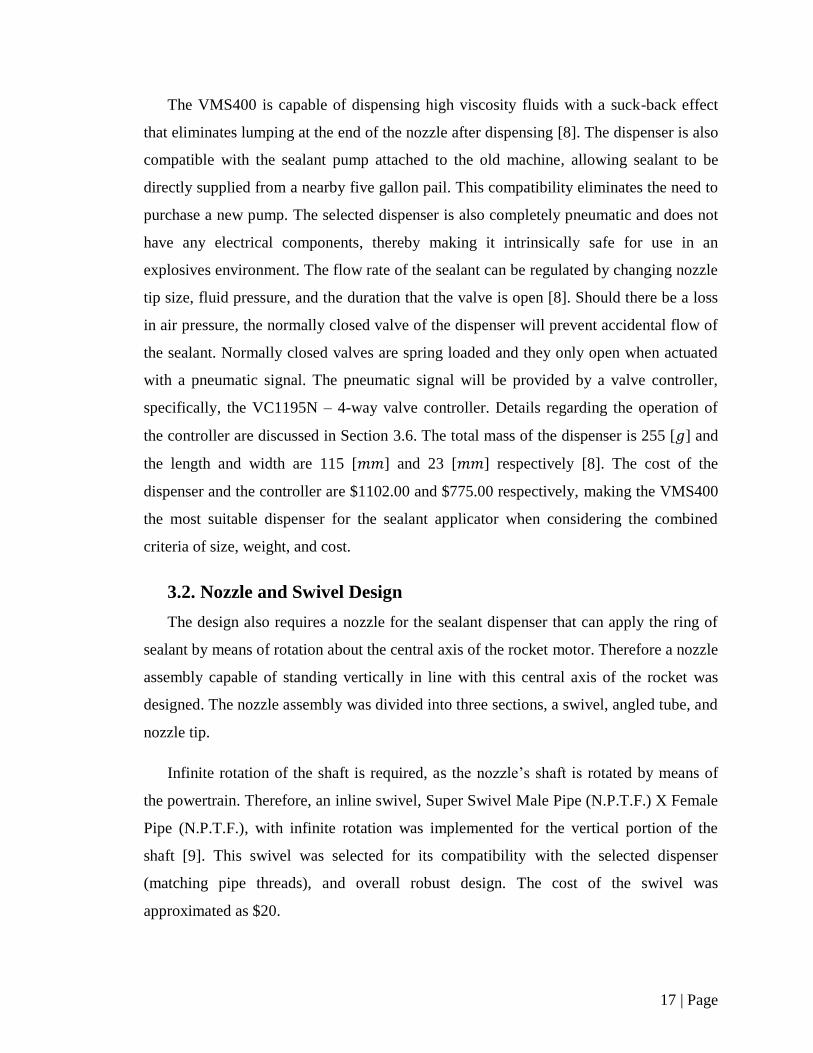
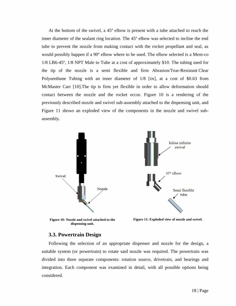
contact between the nozzle and the rocket occur. Figure 10 is a rendering of the
previously described nozzle and swivel sub-assembly attached to the dispensing unit, and
Figure 11 shows an exploded view of the components in the nozzle and swivel sub-
assembly.
Figure 10: Nozzle and swivel attached to the
dispensing unit.
Figure 11: Exploded view of nozzle and swivel.
3.3. Powertrain Design
Following the selection of an appropriate dispenser and nozzle for the design, a
suitable system (or powertrain) to rotate said nozzle was required. The powertrain was
divided into three separate components: rotation source, drivetrain, and bearings and
integration. Each component was examined in detail, with all possible options being
considered.
19 | Page
3.3.1. Rotation Source
The rotation source in the design was required to be a device capable of transferring
enough power to rotate the nozzle 360°. A substantial number of options are available to
power this rotation source, including pneumatics, electricity, and hydraulics. After careful
deliberation, pneumatic power was selected as the primary power source for the rotation
device, due to its easy integration into Magellan Aerospace’s current facility. As well,
pneumatic rotary devices were deemed more likely to be explosion proof than electrical
devices, and less cumbersome than hydraulic devices.
With regards to pneumatically powered rotation devices, research showed two
possible variations to choose from: pneumatic rotary actuators, and pneumatic motors. In
general pneumatic motors were found in a wider range of speeds, and could rotate
indefinitely. However, a pneumatic motor configuration would require an external set of
controls, and precise timing in order to stop at exactly 360°. As well, a pneumatic motor
would not be able to link directly to the dispensing head or nozzle selected, and a
drivetrain would be required. A typical pneumatic motor considered is presented in
Figure 12. On the other hand, pneumatic rotary actuators allow for much more precise
rotary motion and are able to be limited to exact values. However, this limitation would
also require extra controls be implemented into the system, as the actuator would need to
rotate in the opposing directions after every greasing cycle. As well, many rotary
actuators are available in female bore configurations, and as such, would allow for
immediate indexing with the grease dispenser. This would eliminate the need for any
form of drivetrain. A typical rotary actuator considered is presented in Figure 13. Due to
the merits of both systems, both were investigated in further detail.
Figure 12: Typical pneumatic motor [11] .
Figure 13: Typical pneumatic actuator [12].
20 | Page
Many different suppliers were examined in researching pneumatic rotary actuators,
including Bimba, Parker, Phd Inc., Festo, and Rotomation. A set of constraints were
determined to evaluate the products offered by each supplier. These constraints are
summarized in TABLE VII.
TABLE VII: PNEUMATIC ROTARY ACTUATOR CONSTRAINTS
Constraint Value
Supplier Location Canada or United States of America
Component Size Able to fit into 4.25 [ ] by 4.25 [ ] box for modular
expansion
Nominal Rotation 360°
Safety Requirements Explosion Proof/ Safe for use in explosives environments
After thoroughly evaluating every possible manufacturer, no commercially available
products satisfying all four constraints were found. This is due to rotary actuators’ typical
reliance on a rack and pinion system for rotation, causing them to be very long, extending
outside of the component size constraint. However, it is worth noting that rotary actuators
that satisfy all three other constraints are commonly available, and could be considered if
modularity is not desired.
Due to the lack of appropriate pneumatic rotary actuators, a suitable pneumatic
motor was required instead. It was important to first define the required functionality and
implementation of the motor, in order to examine appropriate motors. An appropriate
nozzle rotation speed was calculated in order to properly select a motor. Using a desired
greasing time of 6 [ ], as implemented in Magellan Aerospace’s current system, the
required speed was calculated as follows [13].
Dependant on the type of drivetrain selected, the required rotational speed of the
motor to achieve 10 [ ] at the nozzle would vary.

21 | Page
Therefore, two general groups of drivetrains were considered prior to selecting an
appropriate motor. The first group consisted of traditional spur gears, helical gears, as
well as pulleys and belts, and sprockets and chain linking the motor to the rotating
nozzle. Due to space constraints, it was determined that these drivetrains could not
achieve speed reduction ratios higher than five. The second group considered consisted of
worm and worm gear assemblies. The motor could either attach directly to the worm, or
to save space, sit vertically and connect with a pair of bevel gears. These configurations
could provide significantly higher reduction ratios of up to twenty or more depending on
component sizes. In the end, the added complexity of worm and bevel gears, as well as
the smaller overall size of the first group, traditional spur gears, helical gears, as well as
pulleys and belts, and sprockets and chain, prompted the team to select the first group
over the second. This determined a target speed range of 2 to 50 [ ] for the motor.
As with the rotary actuator, a wide range of suppliers were researched in selecting an
appropriate motor, including Gast Mfg, Boston Gear, Ingersoll Rand, McMaster Carr,
Deprag, and Parker. A set of constraints for the motor were defined based upon size
limitations, speed requirements, and other considerations. These constraints are presented
in TABLE VIII.
TABLE VIII: PNEUMATIC MOTOR CONSTRAINTS
Constraint Value
Supplier Location Canada or United States of America
Component Size Diameter no larger than 1.625 [ ]
Nominal Rotation
Speed
2 – 50 [ ]
Safety Requirements Explosion Proof/ Safe for use in explosives environments
Each manufacturer’s full product line was evaluated for potential products meeting
the required constraints. The feasibility of each manufacturer with respect to the defined
constraints is presented in TABLE IX.

22 | Page
TABLE IX: MANUFACTURER FEASIBILITY
Manufacturer
Constraints
Supplier
Location
Component
Size
Nominal
Rotation Speed
Safety
Requirements
Gast Mfg. PASS FAIL FAIL PASS
Boston Gear PASS FAIL PASS PASS
Ingersoll Rand PASS FAIL PASS PASS
McMaster Carr PASS PASS PASS PASS
Deprag FAIL PASS PASS PASS
Morita PASS PASS FAIL PASS
Parker FAIL FAIL PASS PASS
McMaster Carr was the only supplier evaluated to offer products meeting all defined
constraints. These products are presented in TABLE X below.
TABLE X: POTENTIAL MCMASTER CARR PNEUMATIC MOTORS [10]
Product Part Number Max Speed [ ] Cost
Mini Air Powered Gearmotors
with Push-to-Connect Fittings
(Reversible)
59815K892 7 $ 1,215.00
Mini Air Powered Gearmotors
with Push-to-Connect Fittings
(Reversible)
59815K882 25 $ 1,060.00
Slimline Nose-Mount Air-
Powered Gearmotors (Flanged
+ Reversible)
4185K11 42 $ 1,601.00
Due to the similarity between all motors, the lowest price option was selected, the 25
[ ] 59815K882. The team also felt that this motor would offer the most easily
attainable gear reduction ratio. After consultations with McMaster Carr, the motor was
found to be a redistribution, with the true part number being MMR-5001. As such, the
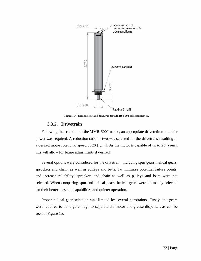
motor was found at Ferguson Engineering for $ 854.00 [14]. A drawing of the final motor
selected, the MMR-5001, is presented in Figure 14.
23 | Page
Figure 14: Dimensions and features for MMR-5001 selected motor.
3.3.2. Drivetrain
Following the selection of the MMR-5001 motor, an appropriate drivetrain to transfer
power was required. A reduction ratio of two was selected for the drivetrain, resulting in
a desired motor rotational speed of 20 [ ]. As the motor is capable of up to 25 [ ],
this will allow for future adjustments if desired.
Several options were considered for the drivetrain, including spur gears, helical gears,
sprockets and chain, as well as pulleys and belts. To minimize potential failure points,
and increase reliability, sprockets and chain as well as pulleys and belts were not
selected. When comparing spur and helical gears, helical gears were ultimately selected
for their better meshing capabilities and quieter operation.
Proper helical gear selection was limited by several constraints. Firstly, the gears
were required to be large enough to separate the motor and grease dispenser, as can be
seen in Figure 15.
24 | Page
Figure 15: Minimum spacing distance between dispenser and motor that gears must satisfy.
Formulaically, the constraint depicted in Figure 15 was defined as follows:
(
)
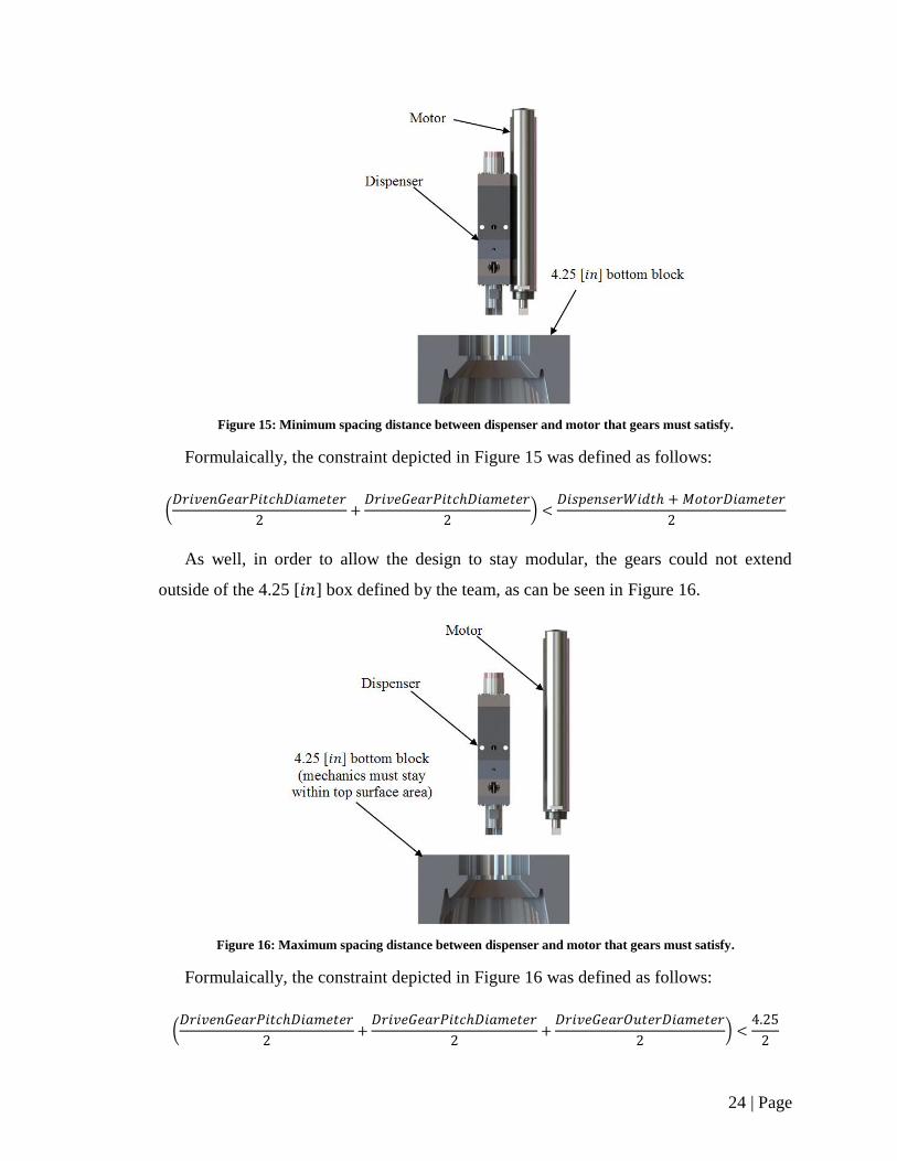
As well, in order to allow the design to stay modular, the gears could not extend
outside of the 4.25 [ ] box defined by the team, as can be seen in Figure 16.
Figure 16: Maximum spacing distance between dispenser and motor that gears must satisfy.
Formulaically, the constraint depicted in Figure 16 was defined as follows:
(
)
25 | Page
Finally, in order to ensure smooth load transfer between teeth, the each gear was
required to have a face width of at least two axial pitches [15]. Formulaically this
constraint is defined as follows:
where
Several gear manufacturers and distributors were considered during the course of the
gear selection process, including W.M.Berg, SDP-SI, McMaster Carr, Boston Gear, and
QTC Gears. In the end, SDP-SI was selected as the manufacturer of choice due to their
wide range of helical gears offered, easy to use website, and low prices.
To select the final gear configuration, drive gears were first chosen with progressively
higher numbers of teeth. An appropriate driven gear was then selected, with a pitch
similar to the drive gear, as well as a number of teeth equivalent to the number of drive
gear teeth multiplied by the reduction ratio. This gear combination was then evaluated
against the previously described size constraints. The first combination to pass all criteria
was chosen, and is presented in TABLE XI.
TABLE XI: CHOSEN GEAR CHARACTERISTICS [16]
Driving Gear Driven Gear
Number of Teeth 25 50
Diametral Pitch (Normal) 48 48
Part No. S1R86Z-P048S025 S1L86Z-P048S050
Cost $ 22.22 $ 34.23
Bore 0.25 [ ] 0.25 [ ]
Face Width 0.187 [ ] 0.187 [ ]
26 | Page
Several options of gear material were available, including stainless steel, commercial
steel, and aluminum. Stainless steel gears were selected over the other materials for their
higher durability, and will allow for a long life drivetrain. As well, to properly actuate,
the driving and driven gears must have differing helix angle directions. As such, the
driving gear was chosen to have a right-hand helix angle, while the driven gear was
chosen to have a left-hand helix angle. The gears will be configured in such a way as the
driving gear pushes up, and the driven gear pushes down, as explained further in Section
3.3.3.
The chosen gears were thoroughly analyzed to determine their performance over a
full lifespan. A summary of the calculated bending and pitting stresses in the gears, along
with their material properties, are presented in TABLE XII. Detailed calculations can be
found in Appendix C.
TABLE XII: BENDING AND PITTING STRESS SUMMARY
Driving Gear [ ] Driven Gear [ ]
Calculated Bending Stress 2800 2637
Acceptable Bending Stress 23622 23622
Calculated Pitting Stress 48493 32984
Acceptable Pitting Stress 74180 74180
As all calculated bending and pitting stresses are well below the acceptable values, it
is known that the gears are safely capable of functioning for over 30 years. The final gear
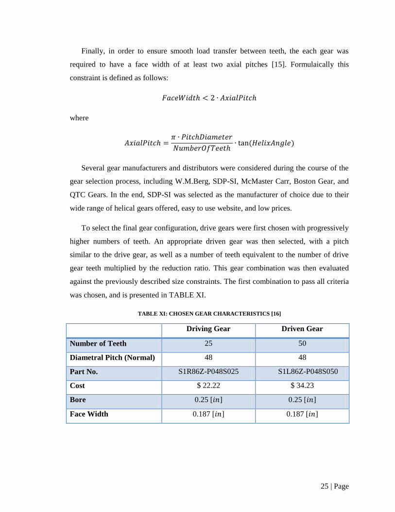
train can be seen as incorporated into the rest of powertrain in Figure 17.
27 | Page
Figure 17: Driving helical gear from motor engaged with nozzle swivel driven helical gear.
With gears chosen, the selected motor characteristics were re-examined in order to
ensure the motor had sufficient torque to drive the gearing at the desired speeds. The
graph in Figure 18 correlates available torque with chosen motor speed.
28 | Page
Figure 18: Graph of motor torque vs. speed for various operating pressures.
At 20 [ ], the desired motor speed, and a 90 [ ] operating pressure the motor
has over 800 [ ] in torque available. This is well over the 5.5 [ ] it requires, as
calculated in Appendix C.
3.3.3. Bearings and Integration
In order to properly integrate the chosen powertrain components with the rest of the
design, appropriate bearing selection was required, along with appropriate gear
modifications to accommodate the swivel.
As the bore of the driving gear is the same size of motor driveshaft, no modifications
were required. The gear can be attached to this driveshaft using the provided set screws in
the gear hub. However, the large total thickness of the gear does not expose any of the
remaining driveshaft, and prevents any indexing into a potential bearing. Therefore the
gear and motor assembly must be suspended from the surface of the indexer. Any
concerns of the gear slipping off the motor driveshaft can be alleviated by operating the
assembly so the drive gear pushes up into to the motor, as opposed to away from it.
29 | Page
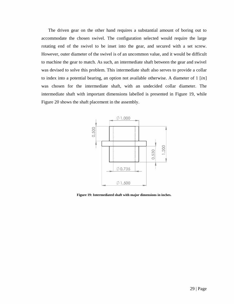
The driven gear on the other hand requires a substantial amount of boring out to
accommodate the chosen swivel. The configuration selected would require the large
rotating end of the swivel to be inset into the gear, and secured with a set screw.
However, outer diameter of the swivel is of an uncommon value, and it would be difficult
to machine the gear to match. As such, an intermediate shaft between the gear and swivel
was devised to solve this problem. This intermediate shaft also serves to provide a collar
to index into a potential bearing, an option not available otherwise. A diameter of 1 [ ]
was chosen for the intermediate shaft, with an undecided collar diameter. The
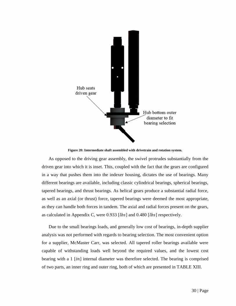
intermediate shaft with important dimensions labelled is presented in Figure 19, while
Figure 20 shows the shaft placement in the assembly.
Figure 19: Intermediated shaft with major dimensions in inches.
30 | Page
Figure 20: Intermediate shaft assembled with drivetrain and rotation system.
As opposed to the driving gear assembly, the swivel protrudes substantially from the
driven gear into which it is inset. This, coupled with the fact that the gears are configured
in a way that pushes them into the indexer housing, dictates the use of bearings. Many
different bearings are available, including classic cylindrical bearings, spherical bearings,
tapered bearings, and thrust bearings. As helical gears produce a substantial radial force,
as well as an axial (or thrust) force, tapered bearings were deemed the most appropriate,
as they can handle both forces in tandem. The axial and radial forces present on the gears,
as calculated in Appendix C, were 0.933 [ ] and 0.480 [ ] respectively.
Due to the small bearings loads, and generally low cost of bearings, in-depth supplier
analysis was not performed with regards to bearing selection. The most convenient option
for a supplier, McMaster Carr, was selected. All tapered roller bearings available were
capable of withstanding loads well beyond the required values, and the lowest cost
bearing with a 1 [ ] internal diameter was therefore selected. The bearing is comprised
of two parts, an inner ring and outer ring, both of which are presented in TABLE XIII.
31 | Page
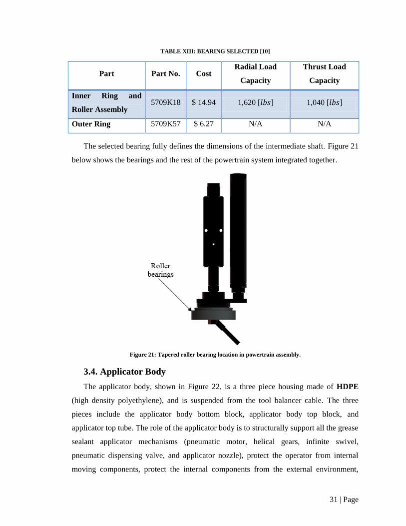
TABLE XIII: BEARING SELECTED [10]
Part Part No. Cost Radial Load
Capacity
Thrust Load
Capacity
Inner Ring and
Roller Assembly 5709K18 $ 14.94 1,620 [ ] 1,040 [ ]
Outer Ring 5709K57 $ 6.27 N/A N/A
The selected bearing fully defines the dimensions of the intermediate shaft. Figure 21
below shows the bearings and the rest of the powertrain system integrated together.
Figure 21: Tapered roller bearing location in powertrain assembly.
3.4. Applicator Body
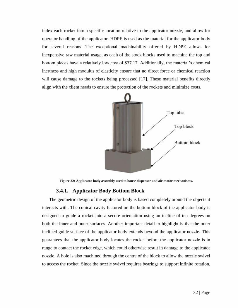
The applicator body, shown in Figure 22, is a three piece housing made of HDPE
(high density polyethylene), and is suspended from the tool balancer cable. The three
pieces include the applicator body bottom block, applicator body top block, and
applicator top tube. The role of the applicator body is to structurally support all the grease
sealant applicator mechanisms (pneumatic motor, helical gears, infinite swivel,
pneumatic dispensing valve, and applicator nozzle), protect the operator from internal
moving components, protect the internal components from the external environment,
32 | Page
index each rocket into a specific location relative to the applicator nozzle, and allow for
operator handling of the applicator. HDPE is used as the material for the applicator body
for several reasons. The exceptional machinability offered by HDPE allows for
inexpensive raw material usage, as each of the stock blocks used to machine the top and
bottom pieces have a relatively low cost of $37.17. Additionally, the material’s chemical
inertness and high modulus of elasticity ensure that no direct force or chemical reaction
will cause damage to the rockets being processed [17]. These material benefits directly
align with the client needs to ensure the protection of the rockets and minimize costs.
Figure 22: Applicator body assembly used to house dispenser and air motor mechanisms.
3.4.1. Applicator Body Bottom Block
The geometric design of the applicator body is based completely around the objects it
interacts with. The conical cavity featured on the bottom block of the applicator body is
designed to guide a rocket into a secure orientation using an incline of ten degrees on
both the inner and outer surfaces. Another important detail to highlight is that the outer
inclined guide surface of the applicator body extends beyond the applicator nozzle. This
guarantees that the applicator body locates the rocket before the applicator nozzle is in
range to contact the rocket edge, which could otherwise result in damage to the applicator
nozzle. A hole is also machined through the centre of the block to allow the nozzle swivel
to access the rocket. Since the nozzle swivel requires bearings to support infinite rotation,
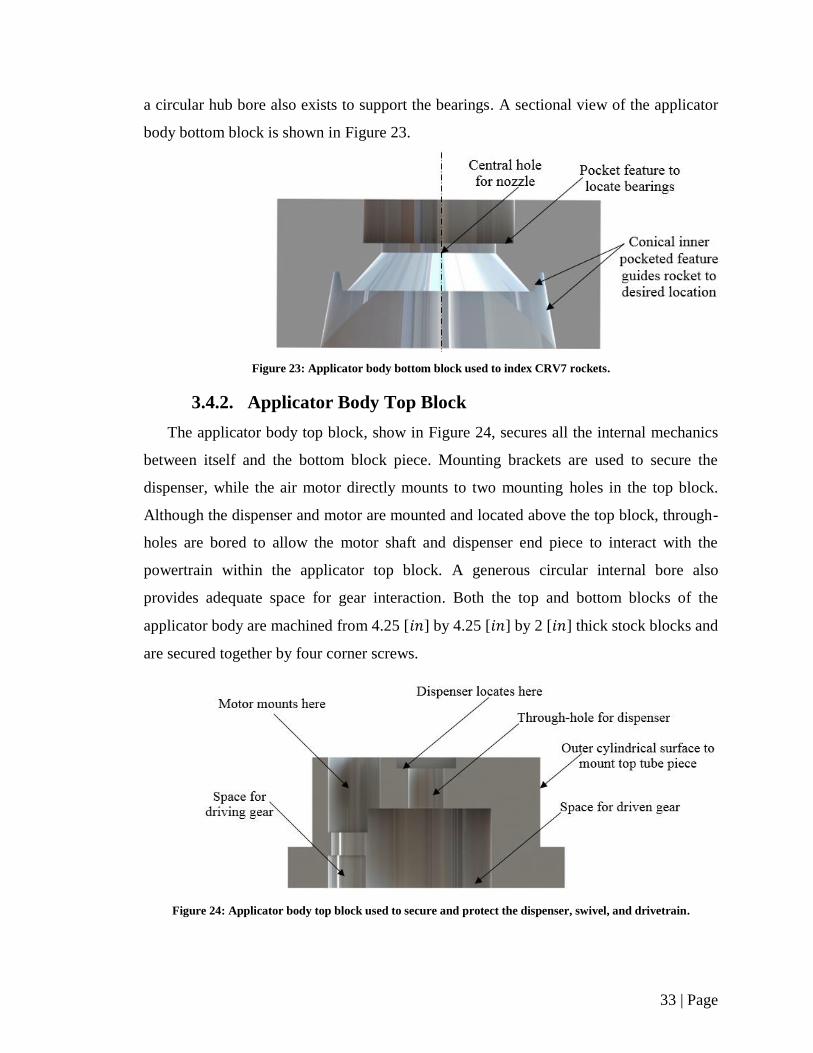
33 | Page
a circular hub bore also exists to support the bearings. A sectional view of the applicator
body bottom block is shown in Figure 23.
Figure 23: Applicator body bottom block used to index CRV7 rockets.
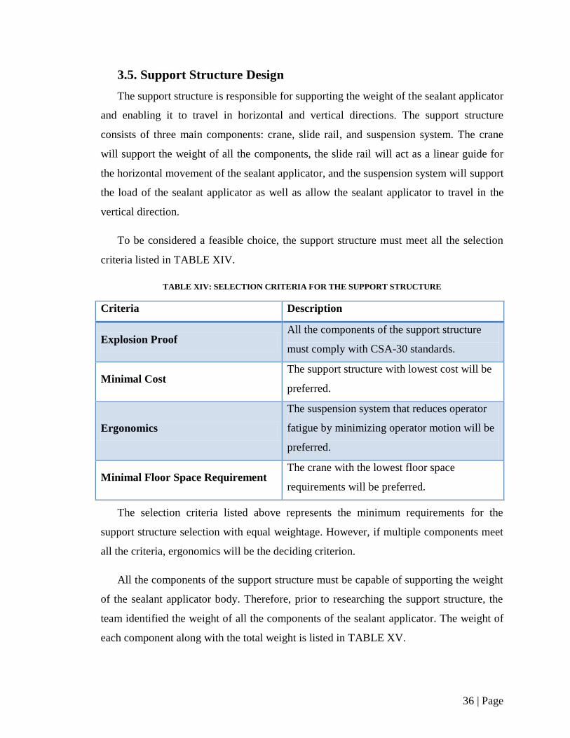
3.4.2. Applicator Body Top Block
The applicator body top block, show in Figure 24, secures all the internal mechanics
between itself and the bottom block piece. Mounting brackets are used to secure the
dispenser, while the air motor directly mounts to two mounting holes in the top block.
Although the dispenser and motor are mounted and located above the top block, through-
holes are bored to allow the motor shaft and dispenser end piece to interact with the
powertrain within the applicator top block. A generous circular internal bore also
provides adequate space for gear interaction. Both the top and bottom blocks of the
applicator body are machined from 4.25 [ ] by 4.25 [ ] by 2 [ ] thick stock blocks and
are secured together by four corner screws.
Figure 24: Applicator body top block used to secure and protect the dispenser, swivel, and drivetrain.

34 | Page
3.4.3. Applicator Top Tube
The third and final piece of the applicator body is the top tube, shown in Figure 25.
Its purpose is to protect the motor and dispenser from direct damage, allow for adequate
space to connect the pneumatic and grease sealant lines, act as a handling point for the
operator, and finally, to serve as a connecting piece to the tool balancing suspension
system. The tube is a 6 [ ] tall, 3.5 [ ] inner diameter, 1/4 [ ] thick HDPE tubing,
which allows it to conceal the internal mechanisms while still being easily handled with
one hand. The top tube connects to the top block piece by two horizontal fasteners. A
similar connection is made between the tube and a bent ¼ [ ] thick metal strip,
ultimately leading to the eye bolt connection point for the tool balance hook to latch onto.
Figure 25: Applicator body tube used to protect the dispenser and motor from direct damage and connect to the
tool balancer cable.
3.4.4. Modular Functionality
In order to facilitate the ability to attach addition applicator modules, the top and
bottom block pieces have been designed with features to allow for modular connection
points. The four corner fasteners used to hold the two block pieces together can be
removed to have a metal strip added on top, which is used to bridge the two adjacent

35 | Page
applicators together. To counteract the bending forces that would be imposed upon these
metal strips if they alone were to connect the modules, holes have been drilled out on the
vertical faces of the bottom block piece to allow for metal pins to be inserted between
modules. These pins will help reduce the stresses in the connection strips, and will help
maintain the relative positions of the two applicator modules to match the rocket
placement within the rocket carts. Figure 26 shows two applicators in dual module
configuration, while Figure 27 shows an exploded view of the module assembly.
Figure 26: Dual module configuration.
Figure 27: Dual applicator module configuration exploded view.
36 | Page
3.5. Support Structure Design
The support structure is responsible for supporting the weight of the sealant applicator
and enabling it to travel in horizontal and vertical directions. The support structure
consists of three main components: crane, slide rail, and suspension system. The crane
will support the weight of all the components, the slide rail will act as a linear guide for
the horizontal movement of the sealant applicator, and the suspension system will support
the load of the sealant applicator as well as allow the sealant applicator to travel in the
vertical direction.
To be considered a feasible choice, the support structure must meet all the selection
criteria listed in TABLE XIV.
TABLE XIV: SELECTION CRITERIA FOR THE SUPPORT STRUCTURE
Criteria Description
Explosion Proof All the components of the support structure
must comply with CSA-30 standards.
Minimal Cost The support structure with lowest cost will be
preferred.
Ergonomics
The suspension system that reduces operator
fatigue by minimizing operator motion will be
preferred.
Minimal Floor Space Requirement The crane with the lowest floor space
requirements will be preferred.
The selection criteria listed above represents the minimum requirements for the
support structure selection with equal weightage. However, if multiple components meet
all the criteria, ergonomics will be the deciding criterion.
All the components of the support structure must be capable of supporting the weight
of the sealant applicator body. Therefore, prior to researching the support structure, the
team identified the weight of all the components of the sealant applicator. The weight of
each component along with the total weight is listed in TABLE XV.
37 | Page
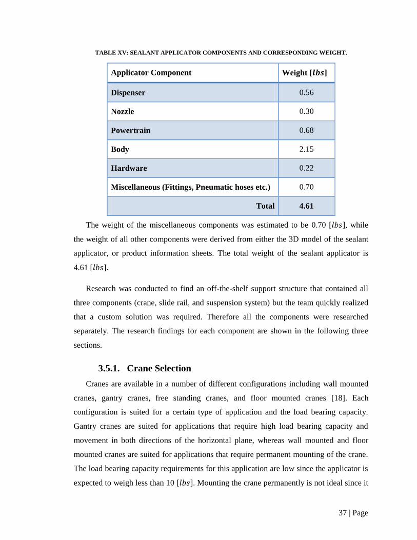
TABLE XV: SEALANT APPLICATOR COMPONENTS AND CORRESPONDING WEIGHT.
Applicator Component Weight [ ]
Dispenser 0.56
Nozzle 0.30
Powertrain 0.68
Body 2.15
Hardware 0.22
Miscellaneous (Fittings, Pneumatic hoses etc.) 0.70
Total 4.61
The weight of the miscellaneous components was estimated to be 0.70 [ ], while
the weight of all other components were derived from either the 3D model of the sealant
applicator, or product information sheets. The total weight of the sealant applicator is
4.61 [ ].
Research was conducted to find an off-the-shelf support structure that contained all
three components (crane, slide rail, and suspension system) but the team quickly realized
that a custom solution was required. Therefore all the components were researched
separately. The research findings for each component are shown in the following three
sections.
3.5.1. Crane Selection
Cranes are available in a number of different configurations including wall mounted
cranes, gantry cranes, free standing cranes, and floor mounted cranes [18]. Each
configuration is suited for a certain type of application and the load bearing capacity.
Gantry cranes are suited for applications that require high load bearing capacity and
movement in both directions of the horizontal plane, whereas wall mounted and floor
mounted cranes are suited for applications that require permanent mounting of the crane.
The load bearing capacity requirements for this application are low since the applicator is
expected to weigh less than 10 [ ]. Mounting the crane permanently is not ideal since it

38 | Page
requires alteration to the facility and the location might change in future. Therefore a free
standing crane is most suited for supporting the sealant applicator. The team researched a
variety of cranes manufactured by different companies, and after evaluating, the TSJ50-
FS-50-8-8 Free Standing Jib Crane (manufactured by Gorbel and supplied by Ergonomic
Partners Inc) was chosen. Figure 28 below shows an image of the crane.
Figure 28: TSJ50-FS-50-8-8 Free Standing Jib Crane [19].
The TSJ50-FS-50-8-8 Free Standing Jib Crane is capable of supporting 50 [ ] of
load which is ten times greater than the expected weight of the sealant applicator. The
boom of the crane has a span of eight feet and is capable of rotating 180° which ensures
that the applicator will be able to index all the rockets in the cart. The height of the crane
is eight feet, which provides more than enough clearance for the applicator to hang above
the rockets placed in the cart. Should there be a future need to relocate the crane, its small
and light structure can be transported easily. The cost of the crane is $660.00 which
makes it the most cost effective solution for supporting the sealant applicator [19].
3.5.2. Slide Rail Selection
The crane mentioned in Section 3.5.1 includes a light tool trolley which can travel on
the linear guide rail attached to the boom of the crane. The applicator suspension system
can be attached to the trolley which enables the suspension system to travel eight feet in
the horizontal plane. The trolley features low friction rollers which prs a feather-light
glide of the tool balancer. Figure 29 shows an image of the trolley.
39 | Page
Figure 29: Tool trolley with arched saddle [20].
3.5.3. Suspension System Selection
The suspension system of the sealant applicator is a tool balancer that balances the
weight of the applicator giving it an apparent weightlessness. Since the load is balanced
at all times, the tool balancer will improve safety and ergonomics which reduces operator
fatigue. Productivity will be increased since the applicator is positioned for immediate
use with minimal operator motion [21].
Tool balancers are available in two main configurations: spring balancers and ratchet
locking balancers. Both configurations include a retractable cable wound on a drum, and
can travel in the vertical direction. The two configurations differ in the locking
mechanism of the cable. Spring balancers feature an automatic drum lock which locks the
cable as soon as the tool is released by the operator. Ratchet lock balancers require the
operator to pull the cable to lock or release the lock [22]. Since spring balancers do not
require operator interference to lock or release the cable, they are considered more
ergonomic than the ratchet lock balancers. Better ergonomics is the deciding criterion for
the suspension system; therefore spring balancers are most suited for supporting the
weight of the sealant applicator. The team researched a variety of spring balancers and
after evaluation, the Endo XA-EW-3 Spring Balancer was chosen. This balancer is
manufactured by Endo Kogyo Co., Ltd. and supplied by Ergonomic Partners Inc. Figure
30 shows an image of Endo XA-EW-3 Spring Balancer with a cut away view
highlighting major components of the balancer.
40 | Page
Figure 30: Image and cut away view of the Endo XA-EW-3 Spring Balancer [24] [25].
The Endo XA-EW-3 Spring Balancer can support 2.2 [ ] to 6.6 [ ] of load.
Unlike other components of the support structure, using the upper-middle range of the
balancer capacity to ensure proper operation is ideal. The sealant applicator weight is
4.61 [ ]. The Endo XA-EW-3 Spring Balancer features a cast aluminum case, forged
swivel hook, and a cable travel of 51.18 [ ]. This spring balancer offers true zero
gravity, without any drifting or strain. The tension of the cable can be adjusted easily by
the operator. The cost of the Endo XA-EW-3 balancer is $239.00, which makes it the
most cost effective suspension system for the sealant applicator [23].
3.6. System Control
Although a detailed analysis for the control system is outside the scope of this project,
a general discussion is presented for consideration when moving forward with design
implementation. The control system is comprised of two sub systems: the pneumatic
control system and the electronic control system. The pneumatic connections and sensors
detect the environment and operator inputs, while the compressed air is used as output
power to all applicator. To accommodate CSA 30 regulations, all electrical processing is
to be done in an explosion proof enclosure or nearby isolated location. The control
41 | Page
information and output power is transferred to the grease sealant applicator through the
pneumatic control system, which interfaces directly.
The digital control is done by a PLC (programmable logic controller), which accepts
inputs from differential pressure sensors, and sends output signals to both the pneumatic
motor and dispenser control unit (the VC1195N Valve controller). The pneumatic output
to the air motor is regulated to the appropriate pressure to run the motor at the correct
speed. The electronic output from the PLC to the VC1195N controller initiates the
dispenser start cycle, which controls the air flow to the dispenser vale, resulting in grease
sealant being dispensed. These two events (dispensing and motor rotation) are synced
together such that the applicator dispenses a complete ring onto a rocket, and stops
rotating and dispensing grease sealant after a full rotation has been made.
The input decides used to dictate the device behaviour are the pneumatic foot petal
(or an equivalent pneumatic press switch), which is pressed by the operator to start a
cycle, and an internal limit switch, which confirms that the applicator is correctly
positioned onto a rocket. The combination of these input devices being active initiates the
start cycle in the PLC.
TABLE XVI presents a summary of the hardware required for the control system, as
well as recommended products and benchmark costs, based on consultation meetings
with Dr. Balakrishnan, a professor at the University of Manitoba currently conducting
research in the robotics and integrated manufacturing [24].
TABLE XVI: CONTROL SYSTEM EQUIPMENT LIST
Item Recommended Part Description Cost
PLC Allen Bradley Pico
1760
Used to control the logic for the motor and
dispenser start cycles $176
Dispenser
Controller
VC1195N Valve
Controller and Foot
Pedal
Converts PLC signal to pneumatic lines to
control dispenser state. Foot pedal included. $775
Contact
Sensor
Crouzet Low Force
Position Detector
Pneumatic contact sensor used to detect
correct indexer placement $42
42 | Page
4. Operations Manual
The following procedure outlines steps to be taken for the successful operation of the
CRV7 sealant application process. The numbers of each step correspond to the time study
completed in Section 5.2.
1. Complete initial sealant applicator inspection as follows:
a. Replace sealant container if necessary.
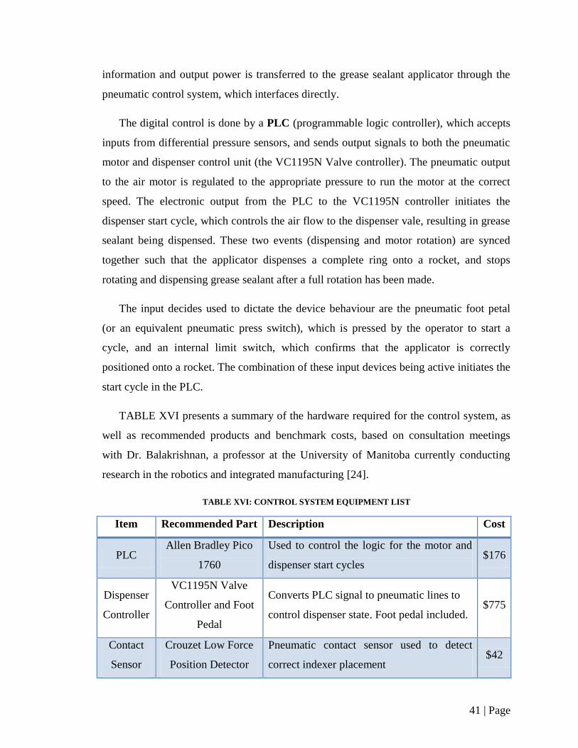
b. Check for any visible changes in sealant within the container such as
slumping, running, or bleeding. [25] (See Figure 31).
Figure 31: DC-4 Silicone Sealant Container [25].
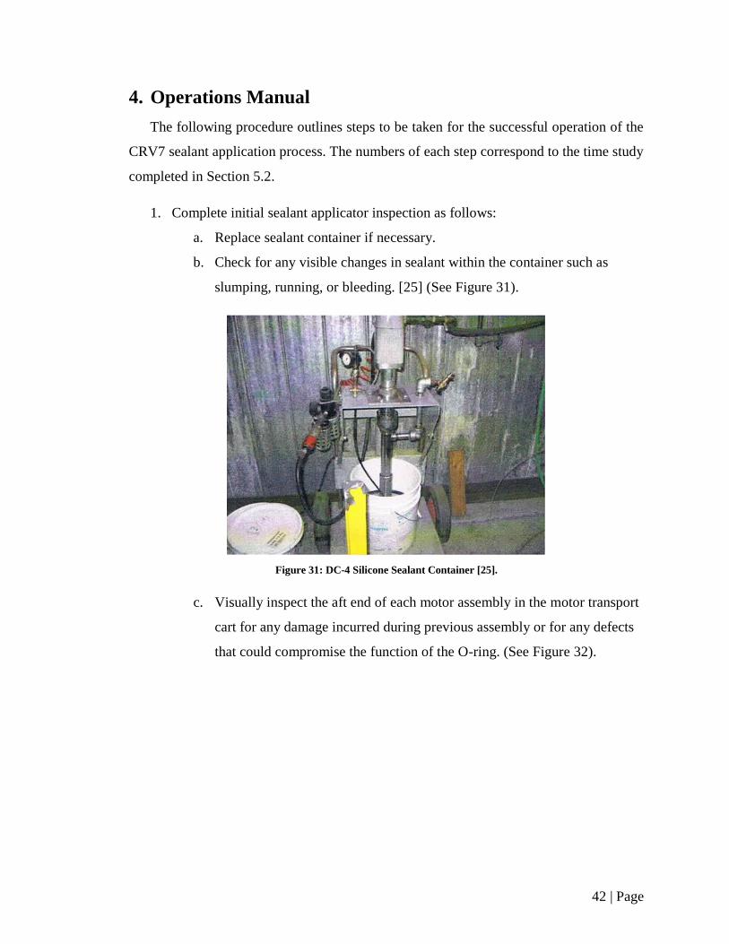
c. Visually inspect the aft end of each motor assembly in the motor transport
cart for any damage incurred during previous assembly or for any defects
that could compromise the function of the O-ring. (See Figure 32).
43 | Page
Figure 32: Inspection of motor aft end [25].
2. Move motor transport cart under the jib crane. Secure the cart position by
activating the manual wheel locks located on the wheel assemblies of the cart.
3. Grab the handle of the sealant applicator and move it to the front end of the cart.
4. Before each batch, perform the sealant dispensed weight test as follows:
a. Dispense one bead of sealant into a motor end cap.
b. Weigh the cap and sealant.
c. Determine the mass of the sealant dispensed. Mass must be within 2 and 3
grams.
d. Adjust the sealant flow as necessary. This is achieved by changing the
fluid pressure by adjusting the regulator attached to the sealant pump.
5. Lower the applicator unto the motor end. Ensure secure applicator placement –
the motor housing rim should lie flat and flush into the dispenser housing groove.
6. Activate dispensing process by depressing the floor pedal.
7. Dispensing takes approximately 6 seconds. The end of the dispensing process can
be audibly confirmed by the silencing of the dispensing air motor.
8. Once completed, lift applicator from motor housing.
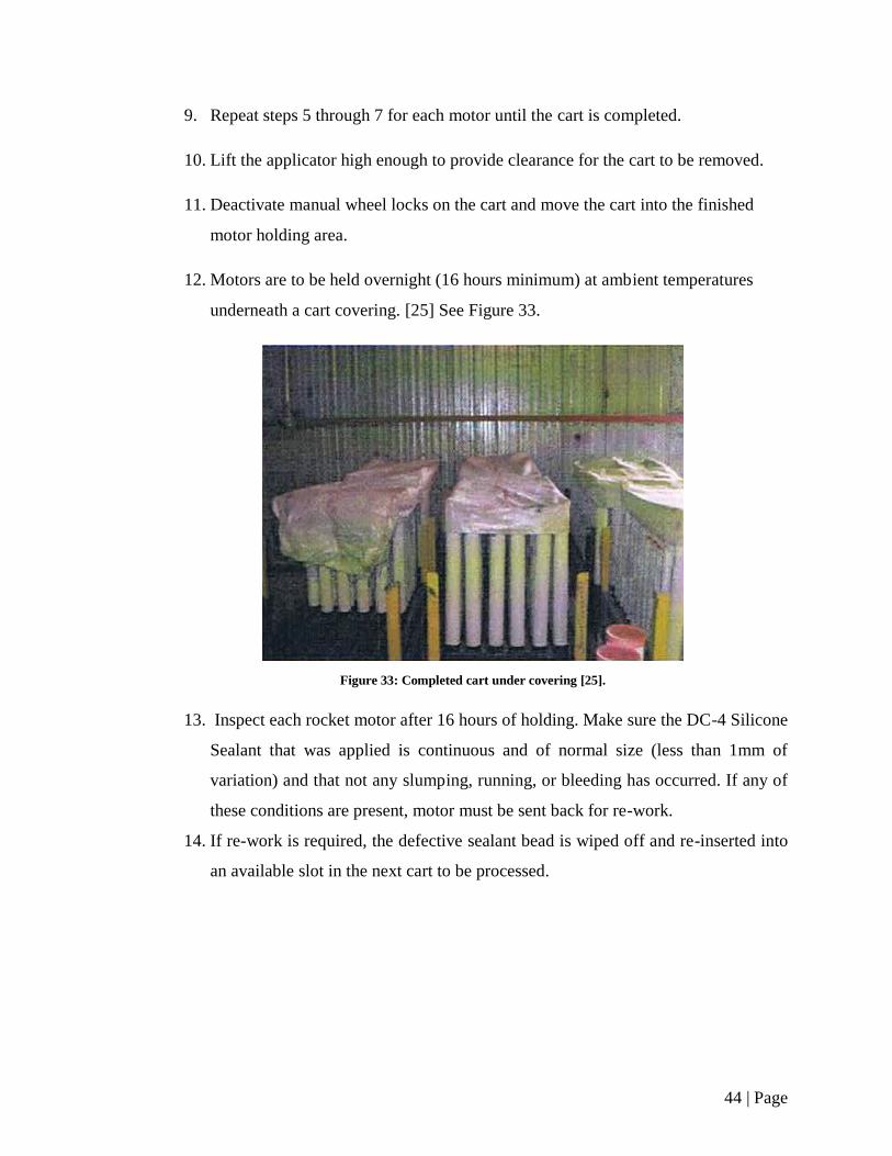
44 | Page
9. Repeat steps 5 through 7 for each motor until the cart is completed.
10. Lift the applicator high enough to provide clearance for the cart to be removed.
11. Deactivate manual wheel locks on the cart and move the cart into the finished
motor holding area.
12. Motors are to be held overnight (16 hours minimum) at ambient temperatures
underneath a cart covering. [25] See Figure 33.
Figure 33: Completed cart under covering [25].
13. Inspect each rocket motor after 16 hours of holding. Make sure the DC-4 Silicone
Sealant that was applied is continuous and of normal size (less than 1mm of
variation) and that not any slumping, running, or bleeding has occurred. If any of
these conditions are present, motor must be sent back for re-work.
14. If re-work is required, the defective sealant bead is wiped off and re-inserted into
an available slot in the next cart to be processed.

45 | Page
5. Cost Analysis
It is essential that the final design be able to apply the sealant to the CRV7 rocket
motor in a cost effective manner. Therefore a detailed cost analysis of the final design
was performed. With the development of the bill of materials, pricing of each component
was determined. The sum of these component prices provides a cost estimate for the
initial capital cost of the assembly. The cost analysis also includes a time study of both
the new design and current process used, allowing for the calculation of money saved due
to the reduction of time in production. As well, lifespan and maintenance estimates
developed give an approximation for the design’s long term expenses. Using all the
developed information, an economic analysis shows the feasibility and benefits to
implementing the new design that is proposed.
5.1. Bill of Materials
The bill of materials for the entire sealant application system is shown in TABLE
XVII. It lists of all the components with their associated costs. These components are
identified in the assembly drawings found in Appendix D.
TABLE XVII: BILL OF MATERIALS FOR THE SEALANT APPLICATION SYSTEM
Part Number Part Name Vendor Cost Per
Unit Qty
Total
Cost
TSJ50-FS-50-8-8 Free Standing Jib
Crane
Ergonomic
Partners Inc. $660.00 1 $660.00
Endo XA-EW-3 Spring Balancer Ergonomic
Partners Inc. $239.00 1 $239.00
VMS-400 Mini Spool Valve Fisnar Inc. $1102.00 1 $1102.00
VC1195N Valve Controller and
Foot Pedal Fisnar Inc. $775.00 1 $775.00
Pico 1760
Programmable
Logic Controller
(PLC)
Allan
Bradley $176.00 1 $176.00
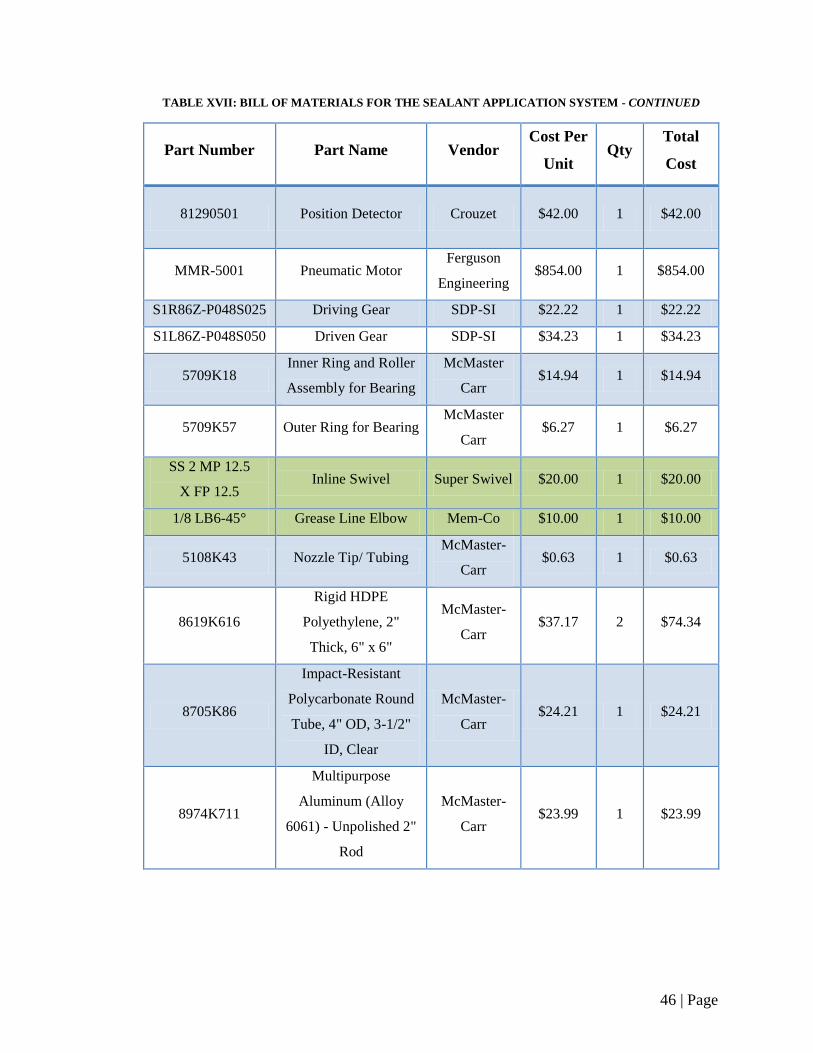
46 | Page
TABLE XVII: BILL OF MATERIALS FOR THE SEALANT APPLICATION SYSTEM - CONTINUED
Part Number Part Name Vendor Cost Per
Unit Qty
Total
Cost
81290501 Position Detector Crouzet $42.00 1 $42.00
MMR-5001 Pneumatic Motor Ferguson
Engineering $854.00 1 $854.00
S1R86Z-P048S025 Driving Gear SDP-SI $22.22 1 $22.22
S1L86Z-P048S050 Driven Gear SDP-SI $34.23 1 $34.23
5709K18 Inner Ring and Roller
Assembly for Bearing
McMaster
Carr $14.94 1 $14.94
5709K57 Outer Ring for Bearing McMaster
Carr $6.27 1 $6.27
SS 2 MP 12.5
X FP 12.5 Inline Swivel Super Swivel $20.00 1 $20.00
1/8 LB6-45° Grease Line Elbow Mem-Co $10.00 1 $10.00
5108K43 Nozzle Tip/ Tubing McMaster-
Carr $0.63 1 $0.63
8619K616
Rigid HDPE
Polyethylene, 2"
Thick, 6" x 6"
McMaster-
Carr $37.17 2 $74.34
8705K86
Impact-Resistant
Polycarbonate Round
Tube, 4" OD, 3-1/2"
ID, Clear
McMaster-
Carr $24.21 1 $24.21
8974K711
Multipurpose
Aluminum (Alloy
6061) - Unpolished 2"
Rod
McMaster-
Carr $23.99 1 $23.99
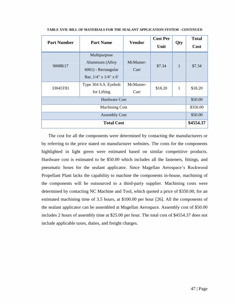
47 | Page
TABLE XVII: BILL OF MATERIALS FOR THE SEALANT APPLICATION SYSTEM - CONTINUED
Part Number Part Name Vendor Cost Per
Unit Qty
Total
Cost
9008K17
Multipurpose
Aluminum (Alloy
6061) - Rectangular
Bar, 1/4" x 1/4" x 6'
McMaster-
Carr $7.34 1 $7.34
33045T81 Type 304 S.S. Eyebolt
for Lifting
McMaster-
Carr $18.20 1 $18.20
Hardware Cost $50.00
Machining Cost $350.00
Assembly Cost $50.00
Total Cost $4554.37
The cost for all the components were determined by contacting the manufacturers or
by referring to the price stated on manufacturer websites. The costs for the components
highlighted in light green were estimated based on similar competitive products.
Hardware cost is estimated to be $50.00 which includes all the fasteners, fittings, and
pneumatic hoses for the sealant applicator. Since Magellan Aerospace’s Rockwood
Propellant Plant lacks the capability to machine the components in-house, machining of
the components will be outsourced to a third-party supplier. Machining costs were
determined by contacting NC Machine and Tool, which quoted a price of $350.00, for an
estimated machining time of 3.5 hours, at $100.00 per hour [26]. All the components of
the sealant applicator can be assembled at Magellan Aerospace. Assembly cost of $50.00
includes 2 hours of assembly time at $25.00 per hour. The total cost of $4554.37 does not
include applicable taxes, duties, and freight charges.
48 | Page
5.2. Time Study
Although a physical model of the design was not created (a prototype is beyond the
scope of this project), a theoretical time study was performed. These times are based on
performing the physical actions required throughout the process. A time was determined
for the sealant application based on the motor operating speed of completing a full
rotation. This speed could be increased in design testing, however this speed was set to
match the current process due to the unknown characteristics of dispensing the silicone
sealant at a faster rate. It should be noted that times are estimates and actual values would
have to be achieved by means of a prototype. Also worth noting is that the sealant weight
test is only required at the end and beginning of sealant application for a given day.
Therefore if multiple carts were having the sealant application performed in a given day
the times would be reduced. This time can be interchanged with the time associated with
moving carts through the workstation. TABLE XVIII on the following page displays
each operation performed in the sealant application to a rocket cart from start to finish for
the new design.
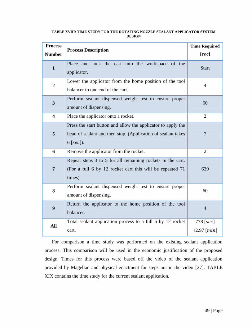
49 | Page
TABLE XVIII: TIME STUDY FOR THE ROTATING NOZZLE SEALANT APPLICATOR SYSTEM
DESIGN
Process
Number Process Description
Time Required
[ ]
1 Place and lock the cart into the workspace of the
applicator. Start
2 Lower the applicator from the home position of the tool
balancer to one end of the cart. 4
3 Perform sealant dispensed weight test to ensure proper
amount of dispensing. 60
4 Place the applicator onto a rocket. 2
5
Press the start button and allow the applicator to apply the
bead of sealant and then stop. (Application of sealant takes
6 [ ]).
7
6 Remove the applicator from the rocket. 2
7
Repeat steps 3 to 5 for all remaining rockets in the cart.
(For a full 6 by 12 rocket cart this will be repeated 71
times)
639
8 Perform sealant dispensed weight test to ensure proper
amount of dispensing. 60
9 Return the applicator to the home position of the tool
balancer. 4
All Total sealant application process to a full 6 by 12 rocket
cart.
778 [ ]
12.97 [ ]
For comparison a time study was performed on the existing sealant application
process. This comparison will be used in the economic justification of the proposed
design. Times for this process were based off the video of the sealant application
provided by Magellan and physical enactment for steps not in the video [27]. TABLE
XIX contains the time study for the current sealant application.
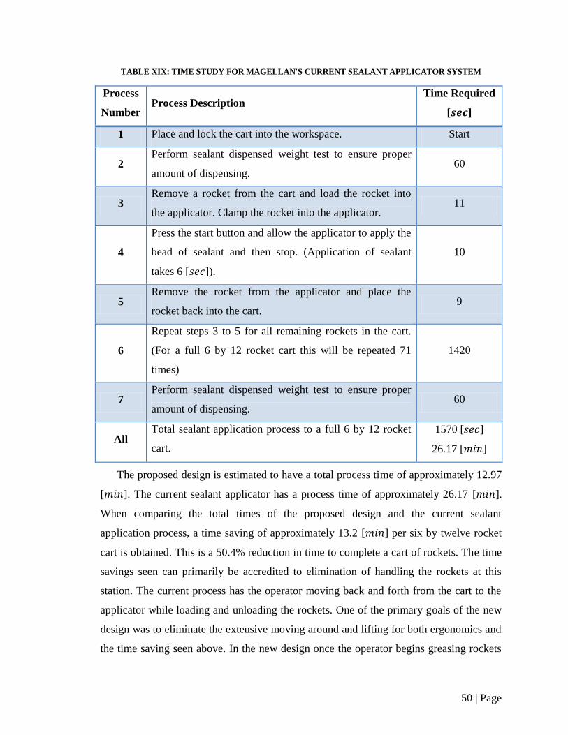
50 | Page
TABLE XIX: TIME STUDY FOR MAGELLAN'S CURRENT SEALANT APPLICATOR SYSTEM
Process
Number Process Description
Time Required
[ ]
1 Place and lock the cart into the workspace. Start
2 Perform sealant dispensed weight test to ensure proper
amount of dispensing. 60
3 Remove a rocket from the cart and load the rocket into
the applicator. Clamp the rocket into the applicator. 11
4
Press the start button and allow the applicator to apply the
bead of sealant and then stop. (Application of sealant
takes 6 [ ]).
10
5 Remove the rocket from the applicator and place the
rocket back into the cart. 9
6
Repeat steps 3 to 5 for all remaining rockets in the cart.
(For a full 6 by 12 rocket cart this will be repeated 71
times)
1420
7 Perform sealant dispensed weight test to ensure proper
amount of dispensing. 60
All Total sealant application process to a full 6 by 12 rocket
cart.
1570 [ ]
26.17 [ ]
The proposed design is estimated to have a total process time of approximately 12.97
[ ]. The current sealant applicator has a process time of approximately 26.17 [ ].
When comparing the total times of the proposed design and the current sealant
application process, a time saving of approximately 13.2 [ ] per six by twelve rocket
cart is obtained. This is a 50.4% reduction in time to complete a cart of rockets. The time
savings seen can primarily be accredited to elimination of handling the rockets at this
station. The current process has the operator moving back and forth from the cart to the
applicator while loading and unloading the rockets. One of the primary goals of the new
design was to eliminate the extensive moving around and lifting for both ergonomics and
the time saving seen above. In the new design once the operator begins greasing rockets
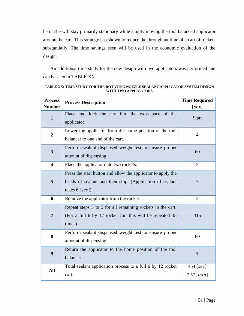
51 | Page
he or she will stay primarily stationary while simply moving the tool balanced applicator
around the cart. This strategy has shown to reduce the throughput time of a cart of rockets
substantially. The time savings seen will be used in the economic evaluation of the
design.
An additional time study for the new design with two applicators was performed and
can be seen in TABLE XX.
TABLE XX: TIME STUDY FOR THE ROTATING NOZZLE SEALANT APPLICATOR SYSTEM DESIGN
WITH TWO APPLICATORS
Process
Number Process Description
Time Required
[ ]
1 Place and lock the cart into the workspace of the
applicator. Start
2 Lower the applicator from the home position of the tool
balancer to one end of the cart. 4
3 Perform sealant dispensed weight test to ensure proper
amount of dispensing. 60
4 Place the applicator onto two rockets. 2
5
Press the start button and allow the applicator to apply the
beads of sealant and then stop. (Application of sealant
takes 6 [ ]).
7
6 Remove the applicator from the rocket. 2
7
Repeat steps 3 to 5 for all remaining rockets in the cart.
(For a full 6 by 12 rocket cart this will be repeated 35
times)
315
8 Perform sealant dispensed weight test to ensure proper
amount of dispensing. 60
9 Return the applicator to the home position of the tool
balancer. 4
All Total sealant application process to a full 6 by 12 rocket
cart.
454 [ ]
7.57 [ ]
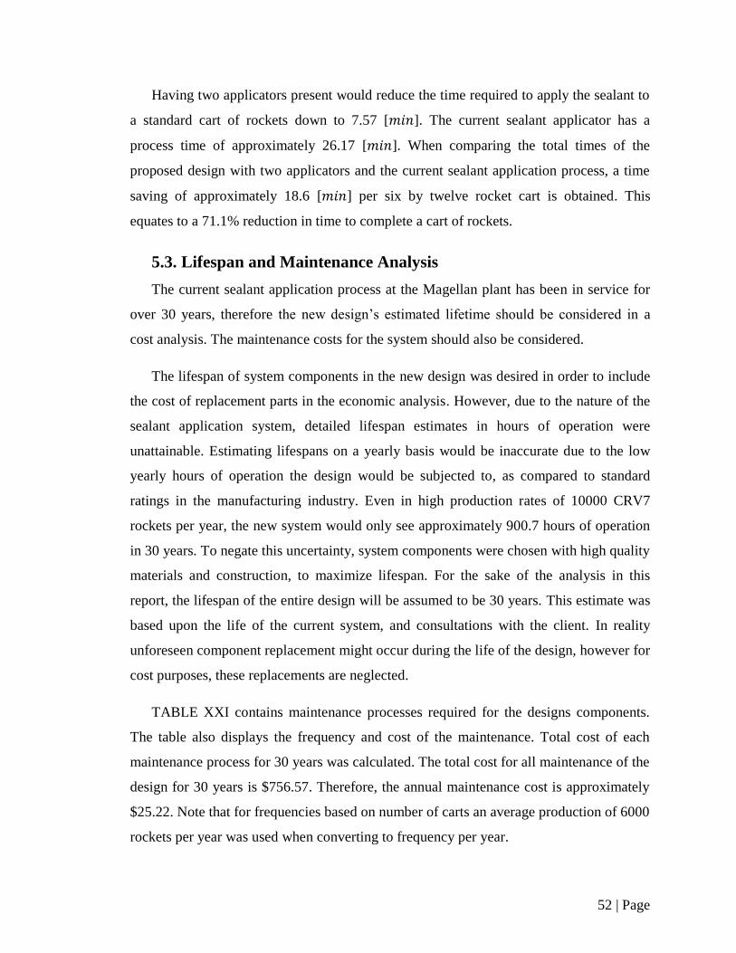
52 | Page
Having two applicators present would reduce the time required to apply the sealant to
a standard cart of rockets down to 7.57 [ ]. The current sealant applicator has a
process time of approximately 26.17 [ ]. When comparing the total times of the
proposed design with two applicators and the current sealant application process, a time
saving of approximately 18.6 [ ] per six by twelve rocket cart is obtained. This
equates to a 71.1% reduction in time to complete a cart of rockets.
5.3. Lifespan and Maintenance Analysis
The current sealant application process at the Magellan plant has been in service for
over 30 years, therefore the new design’s estimated lifetime should be considered in a
cost analysis. The maintenance costs for the system should also be considered.
The lifespan of system components in the new design was desired in order to include
the cost of replacement parts in the economic analysis. However, due to the nature of the
sealant application system, detailed lifespan estimates in hours of operation were
unattainable. Estimating lifespans on a yearly basis would be inaccurate due to the low
yearly hours of operation the design would be subjected to, as compared to standard
ratings in the manufacturing industry. Even in high production rates of 10000 CRV7
rockets per year, the new system would only see approximately 900.7 hours of operation
in 30 years. To negate this uncertainty, system components were chosen with high quality
materials and construction, to maximize lifespan. For the sake of the analysis in this
report, the lifespan of the entire design will be assumed to be 30 years. This estimate was
based upon the life of the current system, and consultations with the client. In reality
unforeseen component replacement might occur during the life of the design, however for
cost purposes, these replacements are neglected.
TABLE XXI contains maintenance processes required for the designs components.
The table also displays the frequency and cost of the maintenance. Total cost of each
maintenance process for 30 years was calculated. The total cost for all maintenance of the
design for 30 years is $756.57. Therefore, the annual maintenance cost is approximately
$25.22. Note that for frequencies based on number of carts an average production of 6000
rockets per year was used when converting to frequency per year.
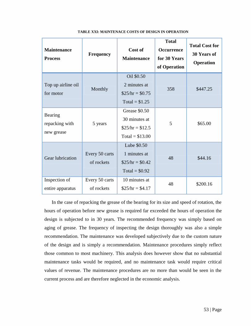
53 | Page
TABLE XXI: MAINTENACE COSTS OF DESIGN IN OPERATION
Maintenance
Process Frequency
Cost of
Maintenance
Total
Occurrence
for 30 Years
of Operation
Total Cost for
30 Years of
Operation
Top up airline oil
for motor Monthly
Oil $0.50
2 minutes at
$25/hr = $0.75
Total = $1.25
358 $447.25
Bearing
repacking with
new grease
5 years
Grease $0.50
30 minutes at
$25/hr = $12.5
Total = $13.00
5 $65.00
Gear lubrication Every 50 carts
of rockets
Lube $0.50
1 minutes at
$25/hr = $0.42
Total = $0.92
48 $44.16
Inspection of
entire apparatus
Every 50 carts
of rockets
10 minutes at
$25/hr = $4.17 48 $200.16
In the case of repacking the grease of the bearing for its size and speed of rotation, the
hours of operation before new grease is required far exceeded the hours of operation the
design is subjected to in 30 years. The recommended frequency was simply based on
aging of grease. The frequency of inspecting the design thoroughly was also a simple
recommendation. The maintenance was developed subjectively due to the custom nature
of the design and is simply a recommendation. Maintenance procedures simply reflect
those common to most machinery. This analysis does however show that no substantial
maintenance tasks would be required, and no maintenance task would require critical
values of revenue. The maintenance procedures are no more than would be seen in the
current process and are therefore neglected in the economic analysis.
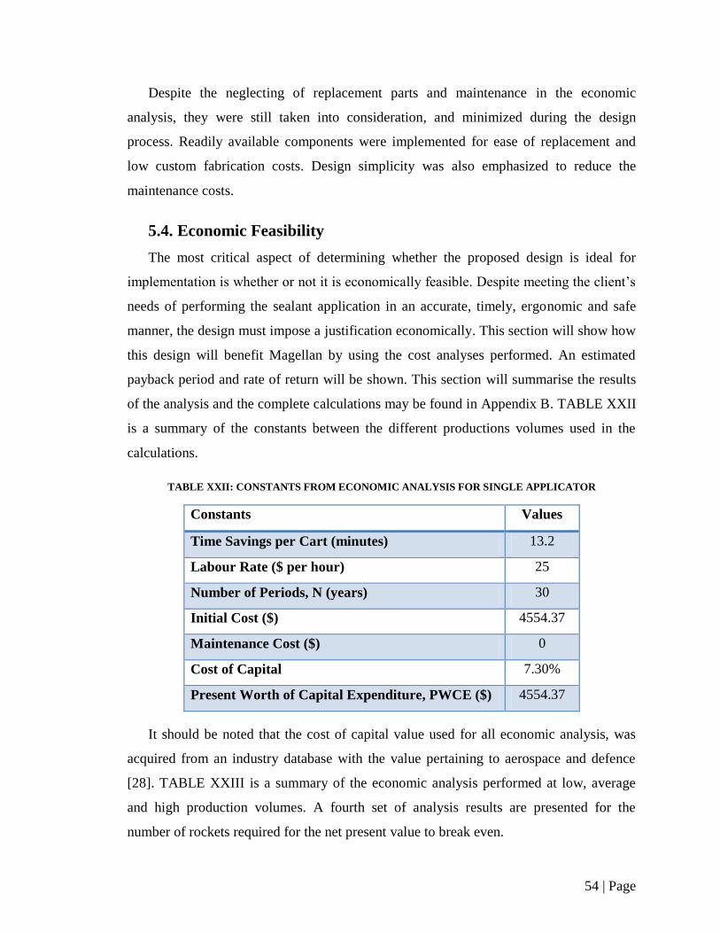
54 | Page
Despite the neglecting of replacement parts and maintenance in the economic
analysis, they were still taken into consideration, and minimized during the design
process. Readily available components were implemented for ease of replacement and
low custom fabrication costs. Design simplicity was also emphasized to reduce the
maintenance costs.
5.4. Economic Feasibility
The most critical aspect of determining whether the proposed design is ideal for
implementation is whether or not it is economically feasible. Despite meeting the client’s
needs of performing the sealant application in an accurate, timely, ergonomic and safe
manner, the design must impose a justification economically. This section will show how
this design will benefit Magellan by using the cost analyses performed. An estimated
payback period and rate of return will be shown. This section will summarise the results
of the analysis and the complete calculations may be found in Appendix B. TABLE XXII
is a summary of the constants between the different productions volumes used in the
calculations.
TABLE XXII: CONSTANTS FROM ECONOMIC ANALYSIS FOR SINGLE APPLICATOR
Constants Values
Time Savings per Cart (minutes) 13.2
Labour Rate ($ per hour) 25
Number of Periods, N (years) 30
Initial Cost ($) 4554.37
Maintenance Cost ($) 0
Cost of Capital 7.30%
Present Worth of Capital Expenditure, PWCE ($) 4554.37
It should be noted that the cost of capital value used for all economic analysis, was
acquired from an industry database with the value pertaining to aerospace and defence
[28]. TABLE XXIII is a summary of the economic analysis performed at low, average
and high production volumes. A fourth set of analysis results are presented for the
number of rockets required for the net present value to break even.
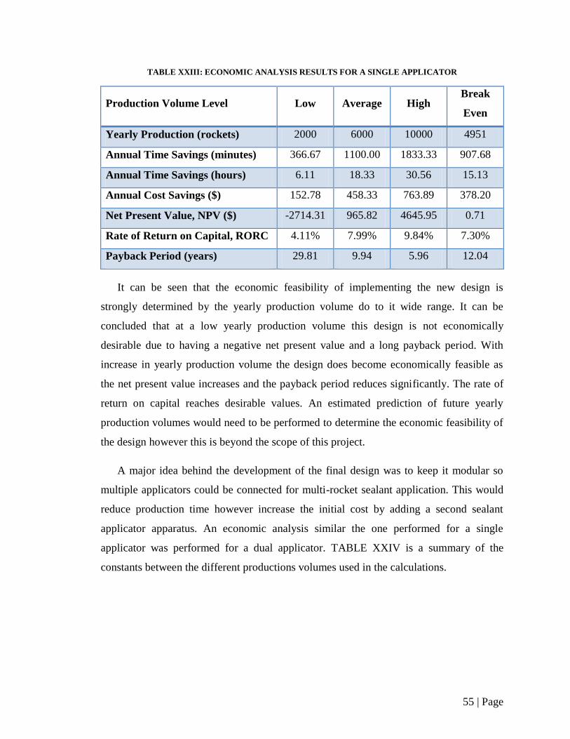
55 | Page
TABLE XXIII: ECONOMIC ANALYSIS RESULTS FOR A SINGLE APPLICATOR
Production Volume Level Low Average High Break
Even
Yearly Production (rockets) 2000 6000 10000 4951
Annual Time Savings (minutes) 366.67 1100.00 1833.33 907.68
Annual Time Savings (hours) 6.11 18.33 30.56 15.13
Annual Cost Savings ($) 152.78 458.33 763.89 378.20
Net Present Value, NPV ($) -2714.31 965.82 4645.95 0.71
Rate of Return on Capital, RORC 4.11% 7.99% 9.84% 7.30%
Payback Period (years) 29.81 9.94 5.96 12.04
It can be seen that the economic feasibility of implementing the new design is
strongly determined by the yearly production volume do to it wide range. It can be
concluded that at a low yearly production volume this design is not economically
desirable due to having a negative net present value and a long payback period. With
increase in yearly production volume the design does become economically feasible as
the net present value increases and the payback period reduces significantly. The rate of
return on capital reaches desirable values. An estimated prediction of future yearly
production volumes would need to be performed to determine the economic feasibility of
the design however this is beyond the scope of this project.
A major idea behind the development of the final design was to keep it modular so
multiple applicators could be connected for multi-rocket sealant application. This would
reduce production time however increase the initial cost by adding a second sealant
applicator apparatus. An economic analysis similar the one performed for a single
applicator was performed for a dual applicator. TABLE XXIV is a summary of the
constants between the different productions volumes used in the calculations.
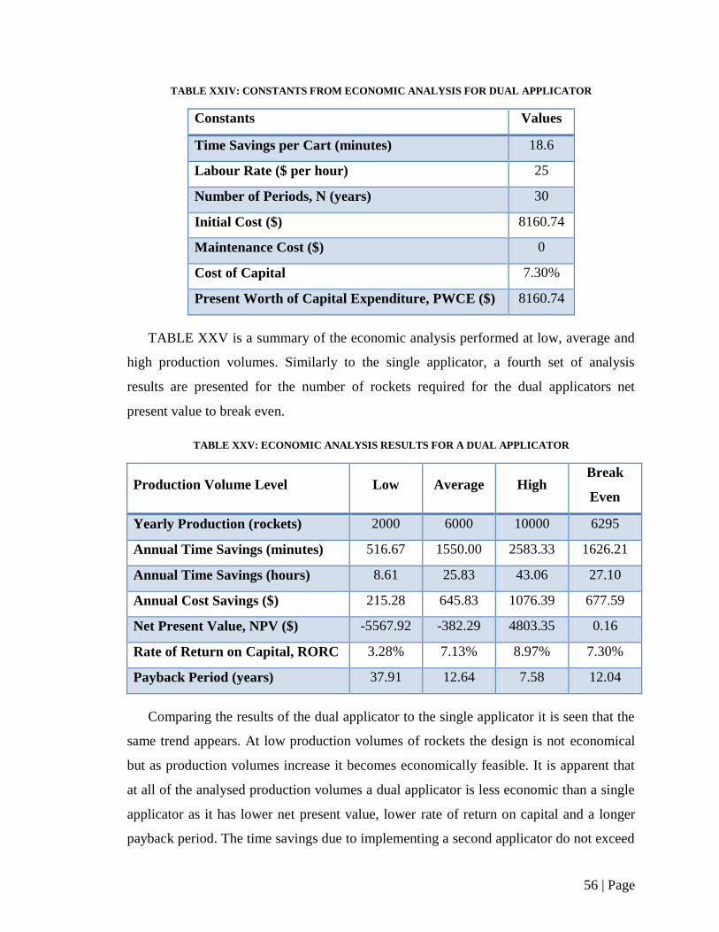
56 | Page
TABLE XXIV: CONSTANTS FROM ECONOMIC ANALYSIS FOR DUAL APPLICATOR
Constants Values
Time Savings per Cart (minutes) 18.6
Labour Rate ($ per hour) 25
Number of Periods, N (years) 30
Initial Cost ($) 8160.74
Maintenance Cost ($) 0
Cost of Capital 7.30%
Present Worth of Capital Expenditure, PWCE ($) 8160.74
TABLE XXV is a summary of the economic analysis performed at low, average and
high production volumes. Similarly to the single applicator, a fourth set of analysis
results are presented for the number of rockets required for the dual applicators net
present value to break even.
TABLE XXV: ECONOMIC ANALYSIS RESULTS FOR A DUAL APPLICATOR
Production Volume Level Low Average High Break
Even
Yearly Production (rockets) 2000 6000 10000 6295
Annual Time Savings (minutes) 516.67 1550.00 2583.33 1626.21
Annual Time Savings (hours) 8.61 25.83 43.06 27.10
Annual Cost Savings ($) 215.28 645.83 1076.39 677.59
Net Present Value, NPV ($) -5567.92 -382.29 4803.35 0.16
Rate of Return on Capital, RORC 3.28% 7.13% 8.97% 7.30%
Payback Period (years) 37.91 12.64 7.58 12.04
Comparing the results of the dual applicator to the single applicator it is seen that the
same trend appears. At low production volumes of rockets the design is not economical
but as production volumes increase it becomes economically feasible. It is apparent that
at all of the analysed production volumes a dual applicator is less economic than a single
applicator as it has lower net present value, lower rate of return on capital and a longer
payback period. The time savings due to implementing a second applicator do not exceed

57 | Page
the additional initial capital costs. It is recommended that a single applicator design be
implemented from an economic stand point, however if production rates demanded faster
throughput times multi-applicators could be implemented.
The economic analysis did not incorporate the intangible savings that the company
would also benefit from. With the new system, direct handling of rockets is completely
eliminated from the greasing process. The moving of the apparatus by the operator is
design to require minimal effort due to the implementation of the tool balancer and
swivel support structure. Ergonomics is a major part of manufacturing as the operators
will work more efficiently when given a more comfortable job. As well, providing
employees with a desirable place to work creates a strong workforce for the future.
Keeping employees satisfied also ensures their long term commitment to the company,
which prevents constant costs due to hiring and training of new employees. The operator
handling reduction was one of the key design objectives requested by the client.
The new design will also be more reliable and consistent than the current system,
helping to minimize time and materials wasted on defective beads of sealant applied to
rockets which must be removed and reapplied. These cost savings were not included in
the analysis as a quality control analysis would first be required on the current system and
a prototype of the new design for comparison. The reduction of such errors was another
major design requirement set by the client. The analysis also made the assumption that
the current system could simply remain in use if the new design were declined. Although
the current system is still in operation, if it were to cease functioning, its cost of
replacement could be compared to the initial cost of the new design. Incorporating this
major cost of replacement would significantly increase the economic benefit of
implementing the new design.

58 | Page
6. Failure Mode and Effects Analysis (FMEA)
Failure Mode and Effects Analysis (FMEA) is the study of possible ways and severity
to which a product or process may fail. FMEA prioritizes the actions required to be taken
in order to minimize risks of a product or process. The purpose of FMEA is to identify
the risks and then propose a means of eliminating or minimizing the risks. A FMEA risk
analysis was performed on the detailed design. FMEA rates risks on scales from one to
ten on the risk’s severity (SEV), frequency (FREQ) and detection (DET). When rating
severity, one is minor and ten is very high. When rating frequency, one is remote
instances and ten is very frequent. When rating detection, one is easily detectible and ten
is non-detectable. Risk Priority Number (RPN) is the product of the severity, frequency
and detection ratings. RPN ratings can have a value between one and a thousand. RPN
values should be minimized as much as possible. It should be noted that in most cases if
regular maintenance and inspection is performed the RPN number will be reduced.
TABLE XXVI is the FMEA performed on the components of the design. A second
FMEA was performed on the design’s operation processes and is shown in Table XXVII.
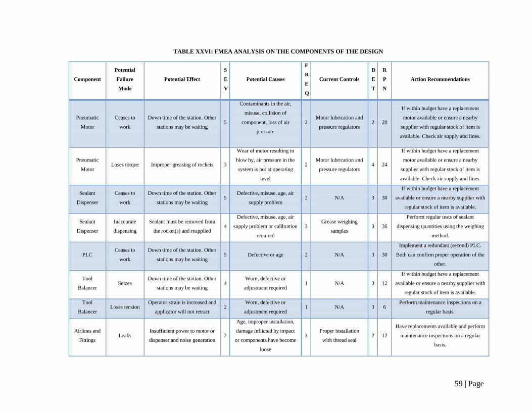
59 | Page
TABLE XXVI: FMEA ANALYSIS ON THE COMPONENTS OF THE DESIGN
Component
Potential
Failure
Mode
Potential Effect
S
E
V
Potential Causes
F
R
E
Q
Current Controls
D
E
T
R
P
N
Action Recommendations
Pneumatic
Motor
Ceases to
work
Down time of the station. Other
stations may be waiting 5
Contaminants in the air,
misuse, collision of
component, loss of air
pressure
2 Motor lubrication and
pressure regulators 2 20
If within budget have a replacement
motor available or ensure a nearby
supplier with regular stock of item is
available. Check air supply and lines.
Pneumatic
Motor Loses torque Improper greasing of rockets 3
Wear of motor resulting in
blow by, air pressure in the
system is not at operating
level
2 Motor lubrication and
pressure regulators 4 24
If within budget have a replacement
motor available or ensure a nearby
supplier with regular stock of item is
available. Check air supply and lines.
Sealant
Dispenser
Ceases to
work
Down time of the station. Other
stations may be waiting 5
Defective, misuse, age, air
supply problem 2 N/A 3 30
If within budget have a replacement
available or ensure a nearby supplier with
regular stock of item is available.
Sealant
Dispenser
Inaccurate
dispensing
Sealant must be removed from
the rocket(s) and reapplied 4
Defective, misuse, age, air
supply problem or calibration
required
3 Grease weighing
samples 3 36
Perform regular tests of sealant
dispensing quantities using the weighing
method.
PLC Ceases to
work
Down time of the station. Other
stations may be waiting 5 Defective or age 2 N/A 3 30
Implement a redundant (second) PLC.
Both can confirm proper operation of the
other.
Tool
Balancer Seizes
Down time of the station. Other
stations may be waiting 4
Worn, defective or
adjustment required 1 N/A 3 12
If within budget have a replacement
available or ensure a nearby supplier with
regular stock of item is available.
Tool
Balancer Loses tension
Operator strain is increased and
applicator will not retract 2
Worn, defective or
adjustment required 1 N/A 3 6
Perform maintenance inspections on a
regular basis.
Airlines and
Fittings Leaks
Insufficient power to motor or
dispenser and noise generation 2
Age, improper installation,
damage inflicted by impact
or components have become
loose
3 Proper installation
with thread seal 2 12
Have replacements available and perform
maintenance inspections on a regular
basis.
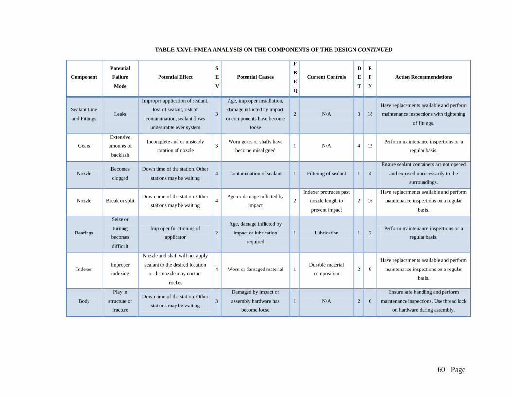
60 | Page
TABLE XXVI: FMEA ANALYSIS ON THE COMPONENTS OF THE DESIGN CONTINUED
Component
Potential
Failure
Mode
Potential Effect
S
E
V
Potential Causes
F
R
E
Q
Current Controls
D
E
T
R
P
N
Action Recommendations
Sealant Line
and Fittings Leaks
Improper application of sealant,
loss of sealant, risk of
contamination, sealant flows
undesirable over system
3
Age, improper installation,
damage inflicted by impact
or components have become
loose
2 N/A 3 18
Have replacements available and perform
maintenance inspections with tightening
of fittings.
Gears
Extensive
amounts of
backlash
Incomplete and or unsteady
rotation of nozzle 3
Worn gears or shafts have
become misaligned 1 N/A 4 12
Perform maintenance inspections on a
regular basis.
Nozzle Becomes
clogged
Down time of the station. Other
stations may be waiting 4 Contamination of sealant 1 Filtering of sealant 1 4
Ensure sealant containers are not opened
and exposed unnecessarily to the
surroundings.
Nozzle Break or split Down time of the station. Other
stations may be waiting 4
Age or damage inflicted by
impact 2
Indexer protrudes past
nozzle length to
prevent impact
2 16
Have replacements available and perform
maintenance inspections on a regular
basis.
Bearings
Seize or
turning
becomes
difficult
Improper functioning of
applicator 2
Age, damage inflicted by
impact or lubrication
required
1 Lubrication 1 2 Perform maintenance inspections on a
regular basis.
Indexer Improper
indexing
Nozzle and shaft will not apply
sealant to the desired location
or the nozzle may contact
rocket
4 Worn or damaged material 1 Durable material
composition 2 8
Have replacements available and perform
maintenance inspections on a regular
basis.
Body
Play in
structure or
fracture
Down time of the station. Other
stations may be waiting 3
Damaged by impact or
assembly hardware has
become loose
1 N/A 2 6
Ensure safe handling and perform
maintenance inspections. Use thread lock
on hardware during assembly.
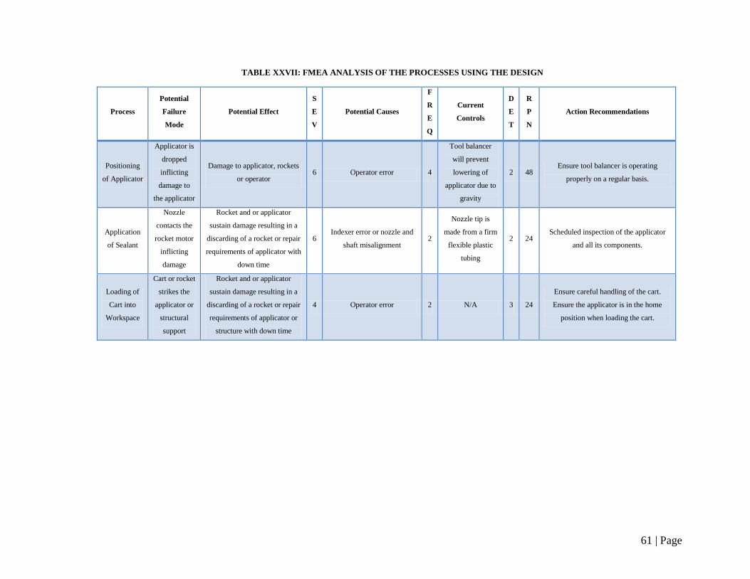
61 | Page
TABLE XXVII: FMEA ANALYSIS OF THE PROCESSES USING THE DESIGN
Process
Potential
Failure
Mode
Potential Effect
S
E
V
Potential Causes
F
R
E
Q
Current
Controls
D
E
T
R
P
N
Action Recommendations
Positioning
of Applicator
Applicator is
dropped
inflicting
damage to
the applicator
Damage to applicator, rockets
or operator 6 Operator error 4
Tool balancer
will prevent
lowering of
applicator due to
gravity
2 48 Ensure tool balancer is operating
properly on a regular basis.
Application
of Sealant
Nozzle
contacts the
rocket motor
inflicting
damage
Rocket and or applicator
sustain damage resulting in a
discarding of a rocket or repair
requirements of applicator with
down time
6 Indexer error or nozzle and
shaft misalignment 2
Nozzle tip is
made from a firm
flexible plastic
tubing
2 24 Scheduled inspection of the applicator
and all its components.
Loading of
Cart into
Workspace
Cart or rocket
strikes the
applicator or
structural
support
Rocket and or applicator
sustain damage resulting in a
discarding of a rocket or repair
requirements of applicator or
structure with down time
4 Operator error 2 N/A 3 24
Ensure careful handling of the cart.
Ensure the applicator is in the home
position when loading the cart.
62 | Page
Based on the Failure Mode and Effects Analysis performed it is clear that the design
presents no risks of major concern. With the highest risk priority number of 48 out of
1000 little risk is present. This can be attributed to the design of the system. The design is
simple in nature with very minimal moving components. The components that do move
are still safe by nature of the movements. The moving of the applicator by the operator is
safe as the operator is not required to input large amounts of force. The powertrain
movement is low risk as the rotating components have minimal mass and angular
velocities which results in low inertia. If failure such as fracture of one of the components
was to occur the ability for material to create significant impact and or travel a significant
distance would be very low. As a level of redundancy the components of the applicator
are all encased within the body, preventing material dispersion. Further redundancy could
be applied by the implementation of safety glasses worn by the operator.
The frequency of failures is also low due to the relatively simple nature of the design.
Logically, the fewer components involved the less chance of failure to occur. The final
aspect for the low risk of the design is the high detectability of error. By keeping the
process semi-automated there can be instant feedback from the operator. The simplistic
nature is once again advantageous, as it allows for easy detection and isolation of
problems.
It should be noted that like all equipment maintenance should be performed to ensure
proper functioning and reduce the chance of failure. Failure of the design could result in
down time of the entire manufacturing process of the CRV7 rocket, and therefore is
highly undesirable. To reduce downtime in times of failure, spare parts could be kept in
inventory if the initial cost associated with them was low. For high cost components risk
of order or repair time is present if failure occurred. Overall, this design can be
considered safe to both the operators and the system environment.
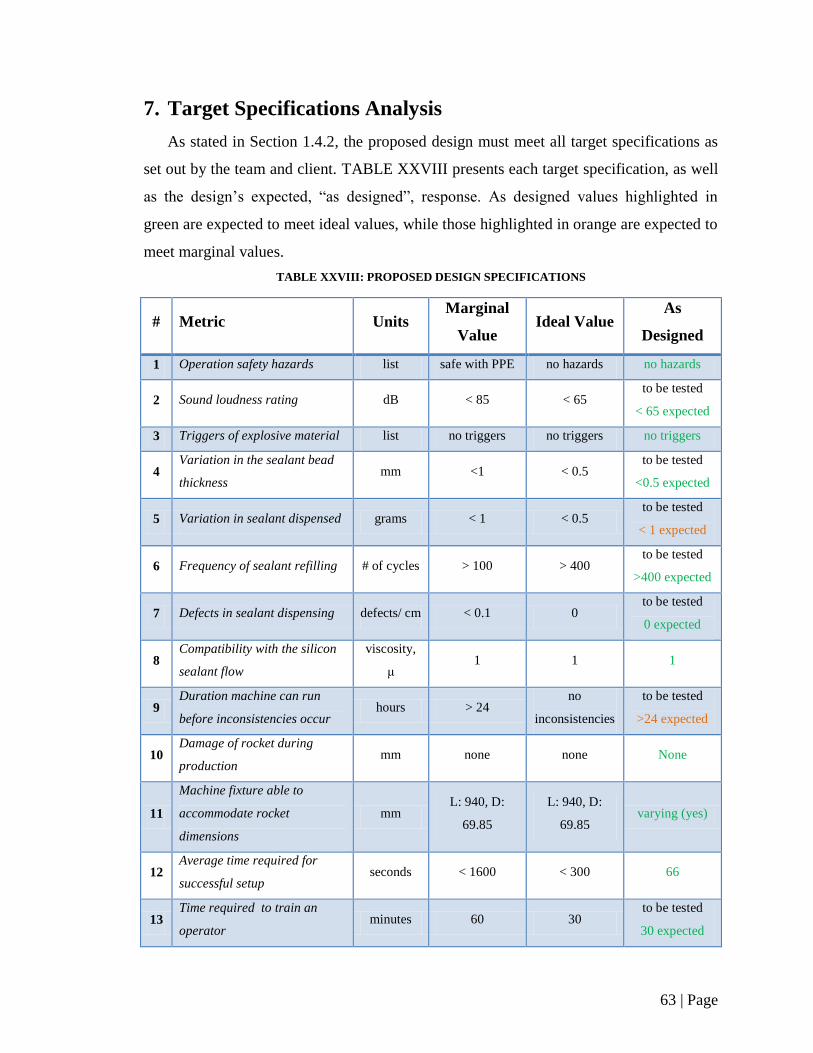
63 | Page
7. Target Specifications Analysis
As stated in Section 1.4.2, the proposed design must meet all target specifications as
set out by the team and client. TABLE XXVIII presents each target specification, as well
as the design’s expected, “as designed”, response. As designed values highlighted in
green are expected to meet ideal values, while those highlighted in orange are expected to
meet marginal values.
TABLE XXVIII: PROPOSED DESIGN SPECIFICATIONS
# Metric Units Marginal
Value Ideal Value
As
Designed
1 Operation safety hazards list safe with PPE no hazards no hazards
2 Sound loudness rating dB < 85 < 65 to be tested
< 65 expected
3 Triggers of explosive material list no triggers no triggers no triggers
4 Variation in the sealant bead
thickness mm <1 < 0.5
to be tested
<0.5 expected
5 Variation in sealant dispensed grams < 1 < 0.5 to be tested
< 1 expected
6 Frequency of sealant refilling # of cycles > 100 > 400 to be tested
>400 expected
7 Defects in sealant dispensing defects/ cm < 0.1 0 to be tested
0 expected
8 Compatibility with the silicon
sealant flow
viscosity,
μ 1 1 1
9 Duration machine can run
before inconsistencies occur hours > 24
no
inconsistencies
to be tested
>24 expected
10 Damage of rocket during
production mm none none None
11
Machine fixture able to
accommodate rocket
dimensions
mm L: 940, D:
69.85
L: 940, D:
69.85 varying (yes)
12 Average time required for
successful setup seconds < 1600 < 300 66
13 Time required to train an
operator minutes 60 30
to be tested
30 expected
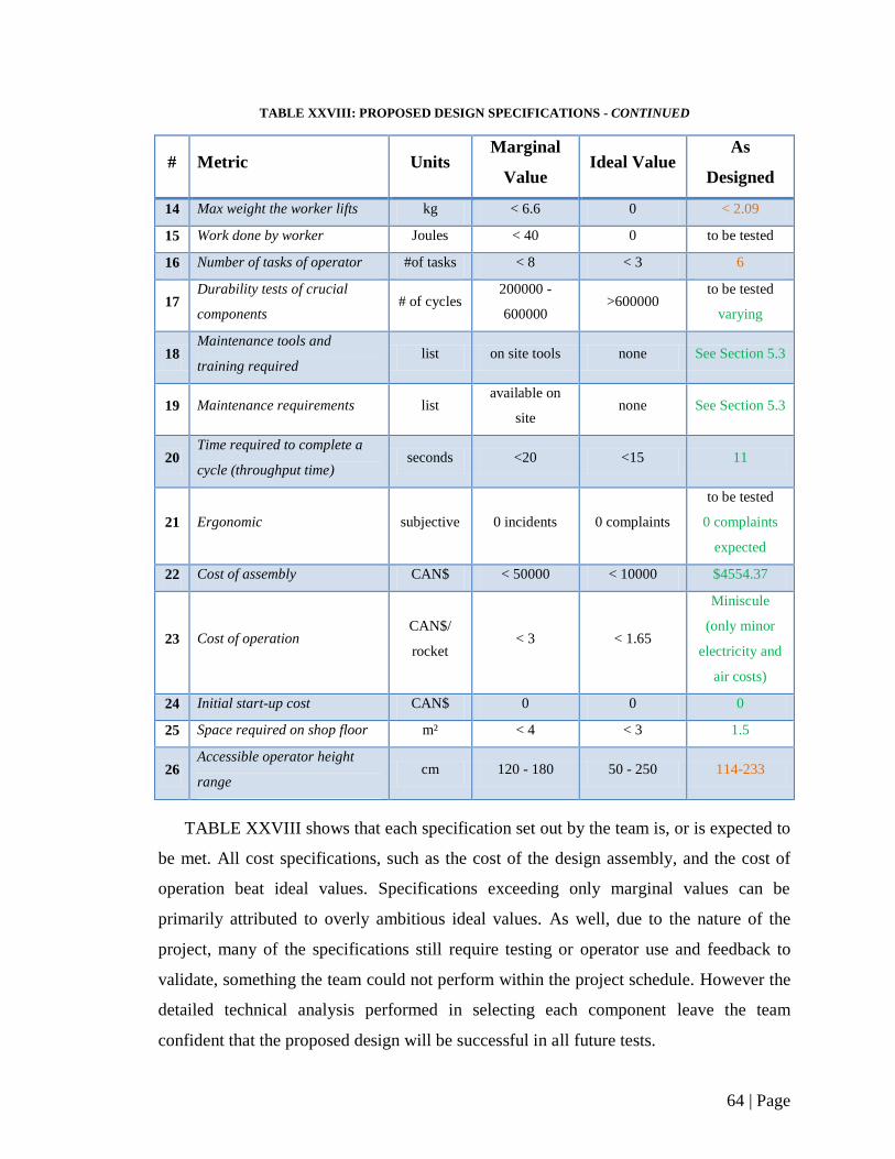
64 | Page
TABLE XXVIII: PROPOSED DESIGN SPECIFICATIONS - CONTINUED
# Metric Units Marginal
Value Ideal Value
As
Designed
14 Max weight the worker lifts kg < 6.6 0 < 2.09
15 Work done by worker Joules < 40 0 to be tested
16 Number of tasks of operator #of tasks < 8 < 3 6
17 Durability tests of crucial
components # of cycles
200000 -
600000 >600000
to be tested
varying
18 Maintenance tools and
training required list on site tools none See Section 5.3
19 Maintenance requirements list available on
site none See Section 5.3
20 Time required to complete a
cycle (throughput time) seconds <20 <15 11
21 Ergonomic subjective 0 incidents 0 complaints
to be tested
0 complaints
expected
22 Cost of assembly CAN$ < 50000 < 10000 $4554.37
23 Cost of operation CAN$/
rocket < 3 < 1.65
Miniscule
(only minor
electricity and
air costs)
24 Initial start-up cost CAN$ 0 0 0
25 Space required on shop floor m² < 4 < 3 1.5
26 Accessible operator height
range cm 120 - 180 50 - 250 114-233
TABLE XXVIII shows that each specification set out by the team is, or is expected to
be met. All cost specifications, such as the cost of the design assembly, and the cost of
operation beat ideal values. Specifications exceeding only marginal values can be
primarily attributed to overly ambitious ideal values. As well, due to the nature of the
project, many of the specifications still require testing or operator use and feedback to
validate, something the team could not perform within the project schedule. However the
detailed technical analysis performed in selecting each component leave the team
confident that the proposed design will be successful in all future tests.
65 | Page
8. Recommendations
After detailed design development and analysis, Perfect 10 Consulting recommends
that Magellan Aerospace implement the design presented in this report. The proposed
design offers a new, more ergonomic, reliable, and cost-effective way to perform sealant
application on CRV7 rockets. The design is composed of two main assemblies, each
broken down into smaller sub-assemblies. The sealant applicator is broken down into the
dispenser, nozzle and swivel, powertrain, and body, while the device suspension is
composed of a crane, tool balancer, and slide rail. The components selected for each
assembly ensure accurate, ergonomic, and reliable sealant application.
Apart from improvements in reliability and ergonomics, the design’s elimination of
direct rocket handing allows for a time savings of over 50% per rocket cart. This time
savings, coupled with the low $4554.37 cost of the new system and its implementation
allows for an economically feasible design.
However, prior to implementation, work still remains on several aspects of the system
that were beyond the required scope. The controls system would require more design
analysis and development, such as determining proper controls system placement in the
factory, PLC programming, and synchronization of the motor and dispenser.
As well, the team recommends the construction of a prototype in order to better
understand the design’s functionality, and expose any potential issues in operator
interaction. Detailed testing remains to be done on several aspects of the design, as can be
seen in TABLE XXVIII.
66 | Page
9. Conclusion
The problem initially proposed the client was to design a new CRV7 sealant
application system that would cut down on operator handling, increase the sealant
dispensing quality, and decrease the production time per rocket. The final design
described in this report is designed with many features to meet each of the client’s needs.
To cut down on operator handling, a hand-guided suspended sealant applicator is
used which glides on a set of tracks to reach positions of each rocket in the cart. The
weight of the applicator is counteracted by a built-in Endo XA-EW-3 Spring Balancer
suspension system, providing efficient operation with little effort from the shop worker.
This is contrasted by the current system in use which requires the shop worker to
manually lift each rocket motor into the apparatus one at a time.
The sealant dispensing quality is increased by the use of a pneumatically powered
sealant dispenser, namely the VMS400 – Mini Spool Valve from Fisnar Inc. This
dispenser provides accurate, adjustable flow of the high viscosity DC-4 Silicone Sealant
used. This accurate controlling comes from the VC1195N 4-way valve controller from
Fisnar Inc. and is located in a separate section of the building. This allows for precise
flow control while complying with CSA-30 explosion proof safety ratings. In addition,
the 360º of nozzle rotation required to apply sealant to the entire inner circumference is
accomplished by a MMR-5001, by Ferguson Engineering, which actuates a 1/8 [ ]
N.P.T.F. inline swivel at the end of the dispenser.
Finally, the overall throughput time for this sealant application process is decreased
significantly from contributions from each feature working in one system. The time
required to complete a full cart of rockets is decreased from the current 26 minutes to
approximately 13 minutes – a 50% time reduction. Furthermore, if two applicators are
used to take advantage of the designs modularity, the 71% time reduction can be realized.
67 | Page
From the economic analysis of the proposed design, an initial cost estimate of
$ 4554.37 results with a breakeven production demand of 4951 rockets annually, and a
maximum rate of return of 9.84%. The proposed design for the sealant application for
CRV7 manufacturing therefore meets the client’s needs and completes the proposed
objectives by providing a solution which improves product quality, production capability,
worker safety and comfort, and is economically advantageous. It is the final
recommendation of Perfect 10 Consulting for Magellan Aerospace to, product demand
forecast permitting, consider further development in prototyping and testing of this
design.
68 | Page
10. Works Cited
[1] "Magellan Aerospace - Rockets and Space," 2013. [Online]. Available:
http://www.magellanaerospace.com/our-products/rockets-and-space. [Accessed 26
September 2013].
[2] K. Braid, Interviewee, (Private Commnication) Photos of Rocket and Sealant
Process. [Interview]. 27 September 2013.
[3] Michael Clendenan, Tyler Kabel, Conrad Kalita, Avi Bahl, Justin Reimer, "Project
Definition Report," University of Manitoba, Winnipeg, 2013.
[4] K. Braid, Interviewee, (Private Communication). [Interview]. 19 September 2013.
[5] T. Kabel, List of Metrics and Units, Winnipeg: Design Eng.,Univ Manitoba, 2013.
[6] Fisnar Inc., "Valves for Precision Dispensing," [Online]. Available:
http://www.fisnar.com/valves_index. [Accessed 18 November 2013].
[7] Fisnar Inc., "710PT-LF - Pinch Tube Valve," [Online]. Available:
http://www.fisnar.com/valves_710pt. [Accessed 18 November 2013].
[8] FIsnar Inc., "VMS400 - Mini-Spool Valve," [Online]. Available:
http://www.fisnar.com/valves_vms400/. [Accessed 18 November 2013].
[9] Super Swivels, "Male Pipe (N.P.T.F.) X Female Pipe (N.P.T.F.)," [Online].
Available: http://superswivels.com/swivels/pg14b.html. [Accessed 18 November
2013].
[10] McMASTER-CARR, "McMASTER-CARR," [Online]. Available:
http://www.mcmaster.com/#. [Accessed November 2013].
[11] McMASTER-CARR, "Stainless Steel Nose-Mount Air-Powered Gear Motors,"
[Online]. Available: http://www.mcmaster.com/#pneumatic-motors/=piv6jq.
[Accessed 9 November 2013].
69 | Page
[12] PHD, Inc., "Series 1000-8000 Heavy Duty Pneumatic & Hydraulic Rotary
Actuator," [Online]. Available:
http://www.phdinc.com/product/?product=rotary&series=18000r. [Accessed 10
November 2013].
[13] K. Braid, Director, P9276449 (Sealant Application Video). [Film]. Magellan
Aerospace, 2013.
[14] Ferguson Engineering, "Micro Motors Order Page," [Online]. Available:
http://fergusonengineering.com/MicroMotor_products.html. [Accessed 14
November 2013].
[15] R. L. Mott, Machine Elements in Mechanical Design, United States of America:
Prentice-Hall Inc., 2001.
[16] Stock Drive Products / Sterling Instrument, "Commercial & Precision Helical Gear
(Inch) Catalog," [Online]. Available: https://sdp-si.com/eStore/Catalog/Group/204.
[Accessed 16 November 2013].
[17] M. P. Groover, Fundamentals of Modern Manufacturing, 4th Edition, USA: John
Wiley & Sons Inc., 2010.
[18] Ergonomic Partners, INC., "Cranes," [Online]. Available:
http://www.ergonomicpartners.com/335/335/category/Cranes/Tool-Balancer-Jib-
Crane/Free-Standing-Tool-Balancer-Jib-Cranes/Cranes.aspx. [Accessed 20
November 2013].
[19] Ergonomic Partners INC., "Gorbel Free Standing Tool Balancer Jib Crane,
Capacity 50 lbs, Span 8 ft, HUB 8 ft, Model TSJ50-FS-50-8-8," [Online].
Available: http://www.ergonomicpartners.com/product/467/992/Gorbel-Free-
Standing-Tool-Balancer-Jib-Crane-Capacity-50-lbs-Span-8-ft-HUB-8-ft-Model-
TSJ50-FS-50-8-8.aspx. [Accessed 20 November 2013].
70 | Page
[20] Gorbel, "Tool Jib Trolley," [Online]. Available:
https://www.gorbel.com/Products/Accessories/tstrolley.aspx. [Accessed 20
November 2013].
[21] L.K. GOODWIN CO. , "Tool Balancers," [Online]. Available:
http://www.lkgoodwin.com/more_info/medium_and_heavy_duty_tool_balancers/
medium_and_heavy_duty_tool_balancers.shtml. [Accessed 20 November 2013].
[22] McMASTER-CARR, "Tool Balancer with Ratchet Lock," [Online]. Available:
http://www.mcmaster.com/#6704a74/=pgocz3. [Accessed 20 November 2013].
[23] Ergonomic Partners INC., "Endo XA-EW-3 Spring Balancer Capacity 2.2-6.6 lbs,"
[Online]. Available: http://www.ergonomicpartners.com/product/395/529/Endo-
XA-EW-3-Spring-Balancer-Capacity-22-66-lbs.aspx. [Accessed 20 November
2013].
[24] D. S. Balakrishnan, Interviewee, Control System Consultation. [Interview]. 6
November 2013.
[25] "Operations Instructions RPI-CRV7-001," Magellan Aerospace, Winnipeg, MB.
[26] NC Machine and Tool, Interviewee, Machining Price Estimate. [Interview]. 26
November 2013.
[27] CRV7 Sealant Application. [Film]. Cananda: Magellan, 2013.
[28] dBase, [Online]. Available: http://www.dbase.com/costs-of-capital-by-industry-
sector/. [Accessed 23 November 2013].

71 | Page
Appendix A
72 | Page
Table of Contents – Appendix A
List of Figures............................................................................................................. 73
List of Tables .............................................................................................................. 74
List of Acronyms ........................................................................................................ 75
1. Concept Generation ........................................................................................... 76
1.1. External Searches ....................................................................................... 76
1.1.1. Standards and Codes ........................................................................... 76
1.1.2. Patents and Literature Searches ........................................................... 77
1.1.3. Competitor’s Products ......................................................................... 77
1.1.4. Discussion with Experts ...................................................................... 79
1.1.5. External Search Summary ................................................................... 79
1.2. Internal Searches ......................................................................................... 79
1.2.1. Internal Search Methodologies ............................................................ 80
1.2.2. Internal Search Results ........................................................................ 81
2. Concept Synthesis, Analysis, and Screening ..................................................... 84
2.1. Phase 1: Initial Screening ........................................................................... 85
2.2. Phase 2: Elimination ................................................................................... 86
2.3. Technical Description and Considerations ................................................. 87
2.4. Phase 3 Final Evaluation ............................................................................ 95
2.5. Recommendations ...................................................................................... 99
2.6. Concept Integration .................................................................................. 101
2.7. Concept Fusion ......................................................................................... 102
3. Works Cited ..................................................................................................... 103
73 | Page
List of Figures
Figure 1: Multi-level hierarchy model of the screening process. ..................................... 84
Figure 2: Circular Track final concept drawing................................................................ 99
Figure 3: Rotating Nozzle Shaft final concept drawing.................................................. 100
Figure 4: 2.5D CNC full concept drawing. ..................................................................... 101
74 | Page
List of Tables
TABLE I: PATENT IDENTIFICATION INFORMATION ............................................ 77
TABLE II: BRAINSTORMED KEY FUNCTIONS ........................................................ 80
TABLE III: BRAINSTORMED CONCEPTS FOR LIFTING ROCKETS FROM
CARTS ............................................................................................................................. 81
TABLE IV: BRAINSTORMED CONCEPTS FOR INDEXING OF ROCKETS AND
CARTS ............................................................................................................................. 82
TABLE V: BRAINSTORMED CONCEPTS FOR GREASING OF THE ROCKET ..... 83
TABLE VI: BRAINSTORMED CONCEPTS FOR REMOVING ROCKETS FROM
MACHINE ....................................................................................................................... 84
TABLE VII: PROS AND CONS FOR TWO MAIN CATEGORIES OF IDEAS........... 85
TABLE VIII SCREENING MATRIX WITH INDIVIDUAL AND AVERAGE
SCORES ........................................................................................................................... 87
TABLE IX: MORPHOLOGICAL BOX FOR THE FROZEN RING PROCESS ........... 88
TABLE X: MORPHOLOGICAL BOX FOR THE CIRCULAR TRACK PROCESS .... 90
TABLE XI: MORPHOLOGICAL BOX FOR THE INVERTED FUNNEL PROCESS . 91
TABLE XII: MORPHOLOGICAL BOX FOR THE ROTATING NOZZLE SHAFT
PROCESS ......................................................................................................................... 92
TABLE XIII: MORPHOLOGICAL BOX FOR THE ROBOT ARM PROCESS ........... 93
TABLE XIV: MORPHOLOGICAL BOX FOR THE 2.5D CNC PROCESS.................. 94
TABLE XV: CRITERIA WEIGHTING MATRIX .......................................................... 96
TABLE XVI: EVALUATION OF CONCEPTS BASED ON PASS/FAIL CRITERIA . 97
TABLE XVII : CONCEPT SCORING MATRIX ........................................................... 98
75 | Page
List of Acronyms
ANSI – American National Standards Institute
BOM – Bill of Materials
CNC – Computer Numerical Control
CAD – Computer Aided Design
CDR – Conceptual Design Report
CP – Continuous Path
CSA – Canadian Standards Association
DOF – Degree of Freedom
PDR – Project Definition Report
PLC – Programmable Logic Controller
PTP – Point to Point
RIA – Robotics Industry Association
TRIZ - Theory of Inventive Problem Solving
3P - Production Preparation Process
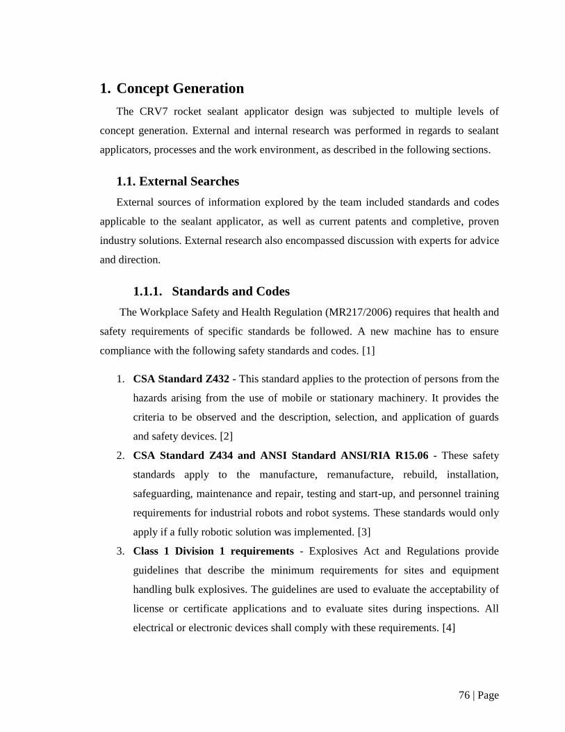
76 | Page
1. Concept Generation
The CRV7 rocket sealant applicator design was subjected to multiple levels of
concept generation. External and internal research was performed in regards to sealant
applicators, processes and the work environment, as described in the following sections.
1.1. External Searches
External sources of information explored by the team included standards and codes
applicable to the sealant applicator, as well as current patents and completive, proven
industry solutions. External research also encompassed discussion with experts for advice
and direction.
1.1.1. Standards and Codes
The Workplace Safety and Health Regulation (MR217/2006) requires that health and
safety requirements of specific standards be followed. A new machine has to ensure
compliance with the following safety standards and codes. [1]
1. CSA Standard Z432 - This standard applies to the protection of persons from the
hazards arising from the use of mobile or stationary machinery. It provides the
criteria to be observed and the description, selection, and application of guards
and safety devices. [2]
2. CSA Standard Z434 and ANSI Standard ANSI/RIA R15.06 - These safety
standards apply to the manufacture, remanufacture, rebuild, installation,
safeguarding, maintenance and repair, testing and start-up, and personnel training
requirements for industrial robots and robot systems. These standards would only
apply if a fully robotic solution was implemented. [3]
3. Class 1 Division 1 requirements - Explosives Act and Regulations provide
guidelines that describe the minimum requirements for sites and equipment
handling bulk explosives. The guidelines are used to evaluate the acceptability of
license or certificate applications and to evaluate sites during inspections. All
electrical or electronic devices shall comply with these requirements. [4]
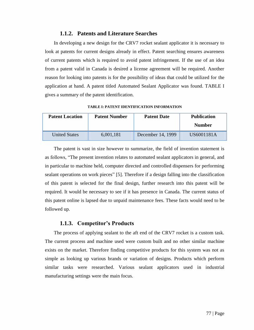
77 | Page
1.1.2. Patents and Literature Searches
In developing a new design for the CRV7 rocket sealant applicator it is necessary to
look at patents for current designs already in effect. Patent searching ensures awareness
of current patents which is required to avoid patent infringement. If the use of an idea
from a patent valid in Canada is desired a license agreement will be required. Another
reason for looking into patents is for the possibility of ideas that could be utilized for the
application at hand. A patent titled Automated Sealant Applicator was found. TABLE I
gives a summary of the patent identification.
TABLE I: PATENT IDENTIFICATION INFORMATION
Patent Location Patent Number Patent Date Publication
Number
United States 6,001,181 December 14, 1999 US6001181A
The patent is vast in size however to summarize, the field of invention statement is
as follows, “The present invention relates to automated sealant applicators in general, and
in particular to machine held, computer directed and controlled dispensers for performing
sealant operations on work pieces” [5]. Therefore if a design falling into the classification
of this patent is selected for the final design, further research into this patent will be
required. It would be necessary to see if it has presence in Canada. The current status of
this patent online is lapsed due to unpaid maintenance fees. These facts would need to be
followed up.
1.1.3. Competitor’s Products
The process of applying sealant to the aft end of the CRV7 rocket is a custom task.
The current process and machine used were custom built and no other similar machine
exists on the market. Therefore finding competitive products for this system was not as
simple as looking up various brands or variation of designs. Products which perform
similar tasks were researched. Various sealant applicators used in industrial
manufacturing settings were the main focus.
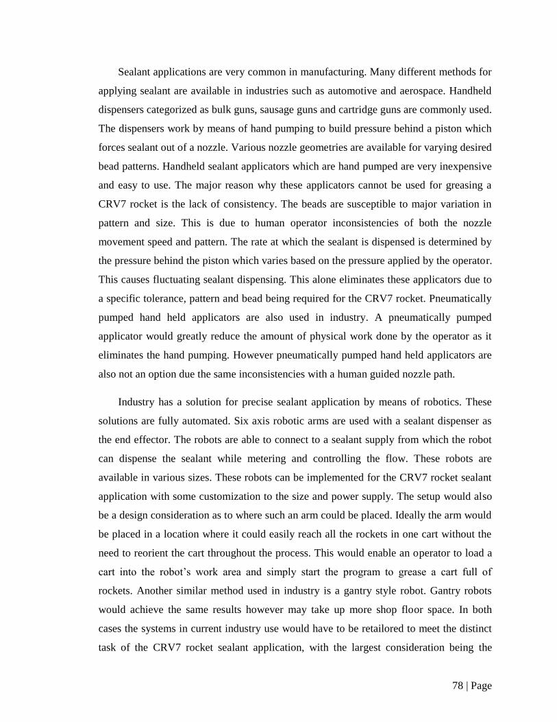
78 | Page
Sealant applications are very common in manufacturing. Many different methods for
applying sealant are available in industries such as automotive and aerospace. Handheld
dispensers categorized as bulk guns, sausage guns and cartridge guns are commonly used.
The dispensers work by means of hand pumping to build pressure behind a piston which
forces sealant out of a nozzle. Various nozzle geometries are available for varying desired
bead patterns. Handheld sealant applicators which are hand pumped are very inexpensive
and easy to use. The major reason why these applicators cannot be used for greasing a
CRV7 rocket is the lack of consistency. The beads are susceptible to major variation in
pattern and size. This is due to human operator inconsistencies of both the nozzle
movement speed and pattern. The rate at which the sealant is dispensed is determined by
the pressure behind the piston which varies based on the pressure applied by the operator.
This causes fluctuating sealant dispensing. This alone eliminates these applicators due to
a specific tolerance, pattern and bead being required for the CRV7 rocket. Pneumatically
pumped hand held applicators are also used in industry. A pneumatically pumped
applicator would greatly reduce the amount of physical work done by the operator as it
eliminates the hand pumping. However pneumatically pumped hand held applicators are
also not an option due the same inconsistencies with a human guided nozzle path.
Industry has a solution for precise sealant application by means of robotics. These
solutions are fully automated. Six axis robotic arms are used with a sealant dispenser as
the end effector. The robots are able to connect to a sealant supply from which the robot
can dispense the sealant while metering and controlling the flow. These robots are
available in various sizes. These robots can be implemented for the CRV7 rocket sealant
application with some customization to the size and power supply. The setup would also
be a design consideration as to where such an arm could be placed. Ideally the arm would
be placed in a location where it could easily reach all the rockets in one cart without the
need to reorient the cart throughout the process. This would enable an operator to load a
cart into the robot’s work area and simply start the program to grease a cart full of
rockets. Another similar method used in industry is a gantry style robot. Gantry robots
would achieve the same results however may take up more shop floor space. In both
cases the systems in current industry use would have to be retailored to meet the distinct
task of the CRV7 rocket sealant application, with the largest consideration being the
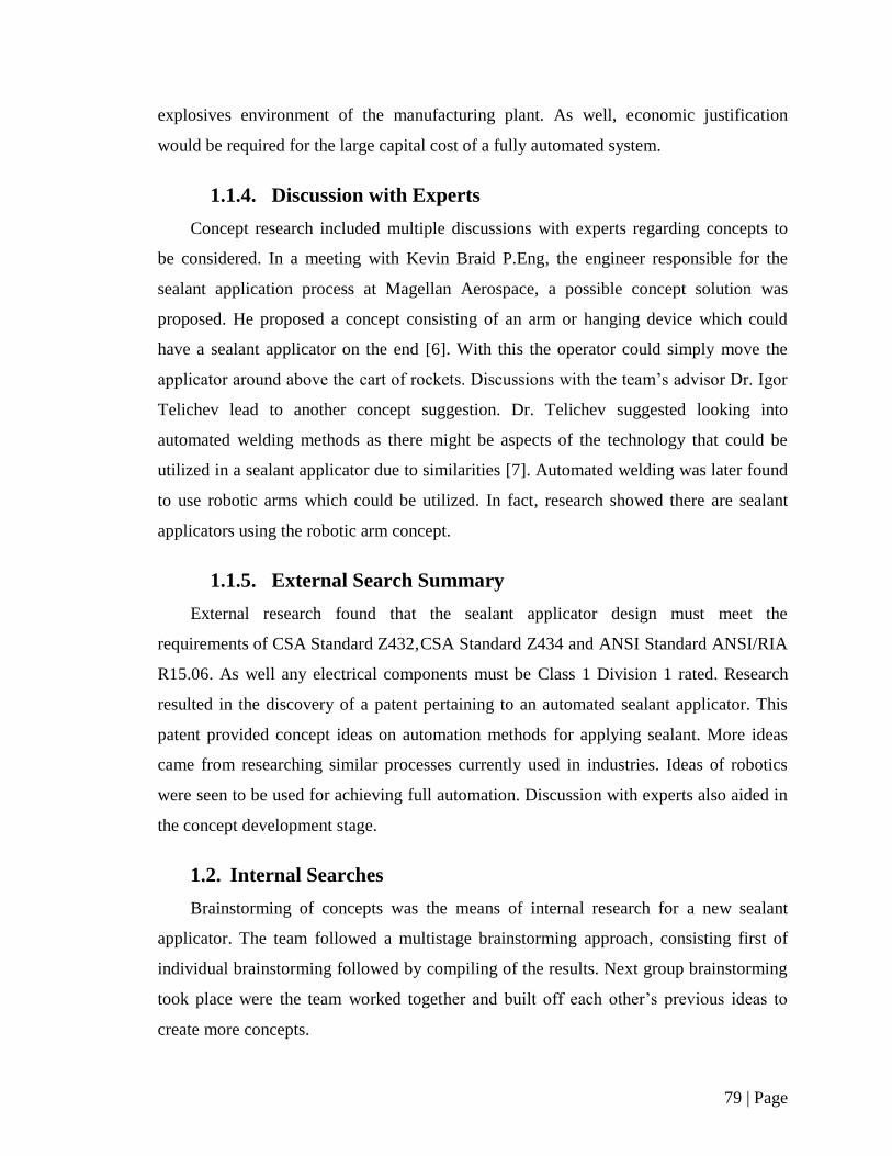
79 | Page
explosives environment of the manufacturing plant. As well, economic justification
would be required for the large capital cost of a fully automated system.
1.1.4. Discussion with Experts
Concept research included multiple discussions with experts regarding concepts to
be considered. In a meeting with Kevin Braid P.Eng, the engineer responsible for the
sealant application process at Magellan Aerospace, a possible concept solution was
proposed. He proposed a concept consisting of an arm or hanging device which could
have a sealant applicator on the end [6]. With this the operator could simply move the
applicator around above the cart of rockets. Discussions with the team’s advisor Dr. Igor
Telichev lead to another concept suggestion. Dr. Telichev suggested looking into
automated welding methods as there might be aspects of the technology that could be
utilized in a sealant applicator due to similarities [7]. Automated welding was later found
to use robotic arms which could be utilized. In fact, research showed there are sealant
applicators using the robotic arm concept.
1.1.5. External Search Summary
External research found that the sealant applicator design must meet the
requirements of CSA Standard Z432, CSA Standard Z434 and ANSI Standard ANSI/RIA
R15.06. As well any electrical components must be Class 1 Division 1 rated. Research
resulted in the discovery of a patent pertaining to an automated sealant applicator. This
patent provided concept ideas on automation methods for applying sealant. More ideas
came from researching similar processes currently used in industries. Ideas of robotics
were seen to be used for achieving full automation. Discussion with experts also aided in
the concept development stage.
1.2. Internal Searches
Brainstorming of concepts was the means of internal research for a new sealant
applicator. The team followed a multistage brainstorming approach, consisting first of
individual brainstorming followed by compiling of the results. Next group brainstorming
took place were the team worked together and built off each other’s previous ideas to
create more concepts.

80 | Page
1.2.1. Internal Search Methodologies
The team’s internal searches began with each team member individually
brainstorming as many possible general solutions to the general problem statement as
possible. An extremely wide range of solutions were discovered, and a more systematic
approach was deemed necessary to better synthesize possible concepts. From the general
brainstorming, two distinct methodologies with regards to greasing the CRV7 rockets in
question were discovered; removing the rocket from its transportation cart into a greasing
machine, or leaving the rockets in its cart and bringing a machine to it instead. Each of
these methodologies were broken down by the team into key functions as presented in
TABLE II.
TABLE II: BRAINSTORMED KEY FUNCTIONS
A. Remove Rockets From Cart B. Keep Rocket In Cart
A1. Lift rocket from cart B1. Index rocket (single) or cart (multiple)
A2. Index rocket into greasing machine B2. Apply grease to rocket
A3. Apply grease to rocket
A4. Remove rocket from machine
Each key function was brainstormed by each team member, with care being taken not
to allow any outside influences or ideas limit the brainstorming. All concepts were
considered valid. A summary of each key function is presented in Section 1.2.2.
Following these searches the team delved into external searches and concept screening.
The team did not follow traditional brainstorming methodologies such as TRIZ
(Theory of Inventive Problem Solving) and 3P (Production Preparation Process). TRIZ
was avoided during preliminary brainstorming as it is designed to better facilitate product
improvements, as opposed to new product creation. 3P was avoided due to a lack of
testing facilities and materials for Moonshining. It was not feasible for the team to
extensively test concepts during this phase.
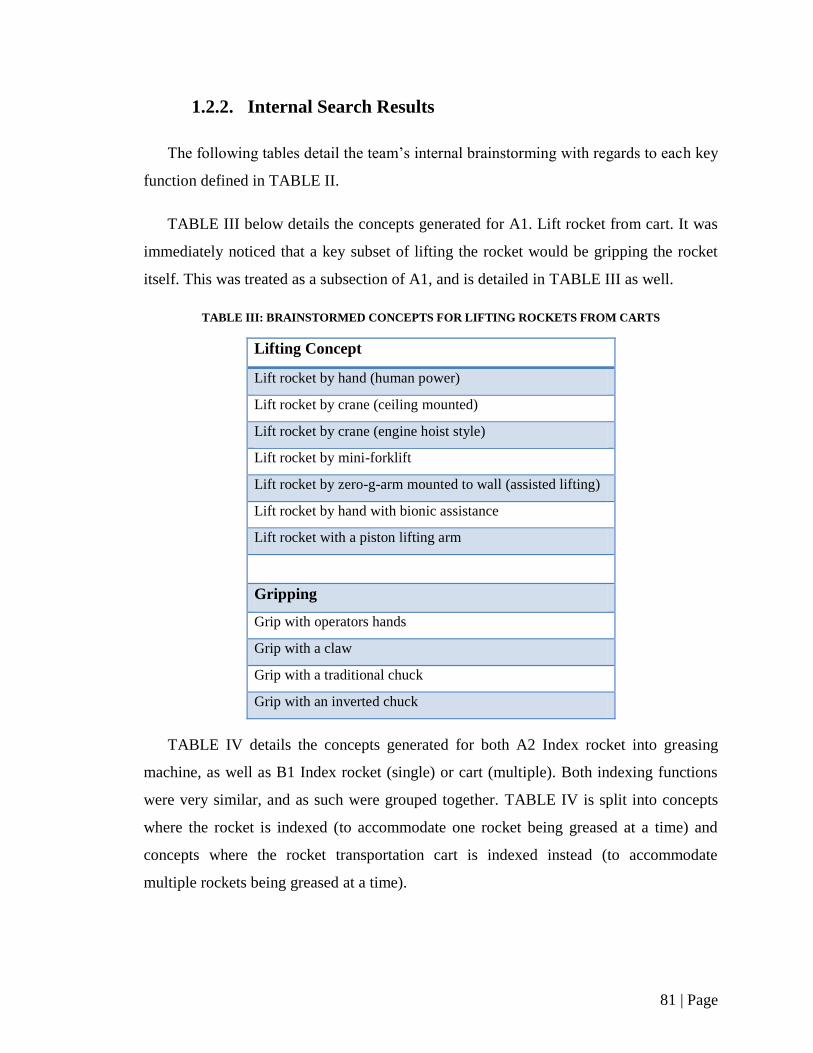
81 | Page
1.2.2. Internal Search Results
The following tables detail the team’s internal brainstorming with regards to each key
function defined in TABLE II.
TABLE III below details the concepts generated for A1. Lift rocket from cart. It was
immediately noticed that a key subset of lifting the rocket would be gripping the rocket
itself. This was treated as a subsection of A1, and is detailed in TABLE III as well.
TABLE III: BRAINSTORMED CONCEPTS FOR LIFTING ROCKETS FROM CARTS
Lifting Concept
Lift rocket by hand (human power)
Lift rocket by crane (ceiling mounted)
Lift rocket by crane (engine hoist style)
Lift rocket by mini-forklift
Lift rocket by zero-g-arm mounted to wall (assisted lifting)
Lift rocket by hand with bionic assistance
Lift rocket with a piston lifting arm
Gripping
Grip with operators hands
Grip with a claw
Grip with a traditional chuck
Grip with an inverted chuck
TABLE IV details the concepts generated for both A2 Index rocket into greasing
machine, as well as B1 Index rocket (single) or cart (multiple). Both indexing functions
were very similar, and as such were grouped together. TABLE IV is split into concepts
where the rocket is indexed (to accommodate one rocket being greased at a time) and
concepts where the rocket transportation cart is indexed instead (to accommodate
multiple rockets being greased at a time).
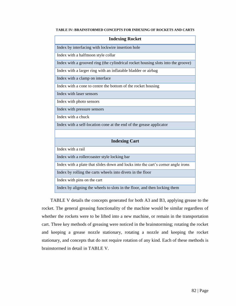
82 | Page
TABLE IV: BRAINSTORMED CONCEPTS FOR INDEXING OF ROCKETS AND CARTS
Indexing Rocket
Index by interfacing with lockwire insertion hole
Index with a halfmoon style collar
Index with a grooved ring (the cylindrical rocket housing slots into the groove)
Index with a larger ring with an inflatable bladder or airbag
Index with a clamp on interface
Index with a cone to centre the bottom of the rocket housing
Index with laser sensors
Index with photo sensors
Index with pressure sensors
Index with a chuck
Index with a self-location cone at the end of the grease applicator
Indexing Cart
Index with a rail
Index with a rollercoaster style locking bar
Index with a plate that slides down and locks into the cart’s corner angle irons
Index by rolling the carts wheels into divets in the floor
Index with pins on the cart
Index by aligning the wheels to slots in the floor, and then locking them
TABLE V details the concepts generated for both A3 and B3, applying grease to the
rocket. The general greasing functionality of the machine would be similar regardless of
whether the rockets were to be lifted into a new machine, or remain in the transportation
cart. Three key methods of greasing were noticed in the brainstorming; rotating the rocket
and keeping a grease nozzle stationary, rotating a nozzle and keeping the rocket
stationary, and concepts that do not require rotation of any kind. Each of these methods is
brainstormed in detail in TABLE V.

83 | Page
TABLE V: BRAINSTORMED CONCEPTS FOR GREASING OF THE ROCKET
Rotating the Rocket
Grease by the “old system”; a rotating index point on the bottom of a machine, with a grease
nozzle inserting from above.
Grease by integrating rotating cones into the bottom of carts, and having a moveable fixed nozzle
to coordinate with it.
Grease by having two wheels clamp on the side of the rocket, and spin it under a fixed applicator.
Grease by resting the rockets horizontally and spinning them with a fixed applicator inside.
Grease by rolling the rockets down an incline and having a CNC arm shoot in to dispense grease.
Grease by rolling the rockets down an incline and having an indexed nozzle follow the rocket
down the incline.
Grease by having a robot arm grip the rocket and spin it underneath a stationary nozzle.
Nozzle Rotating/Moving
Grease by having a grease dispensing arm on a circular track outside of the rocket, with the
nozzle facing inwards.
Grease by having a grease dispensing arm on a circular track inside the rocket, with the nozzle
facing outwards.
Grease by having the nozzle rotate on a shaft.
Grease by having grease applied by a CNC robotic arm in a preprogrammed fashion.
Grease by having a machine hook onto the edge of the rocket and drive around the lip (like a can
opener).
Grease by having a corkscrew framework force a grease applicator to spin.
Grease by having a 2.5D CNC apply grease in a preprogrammed fashion.
Non Rotating Concepts
Grease by freezing rings of sealant to place into rockets and thaw
Grease by pumping grease out an inverted funnel
Grease by pumping grease out of many nozzles, so a droplet from each nozzle touches the droplet
beside it
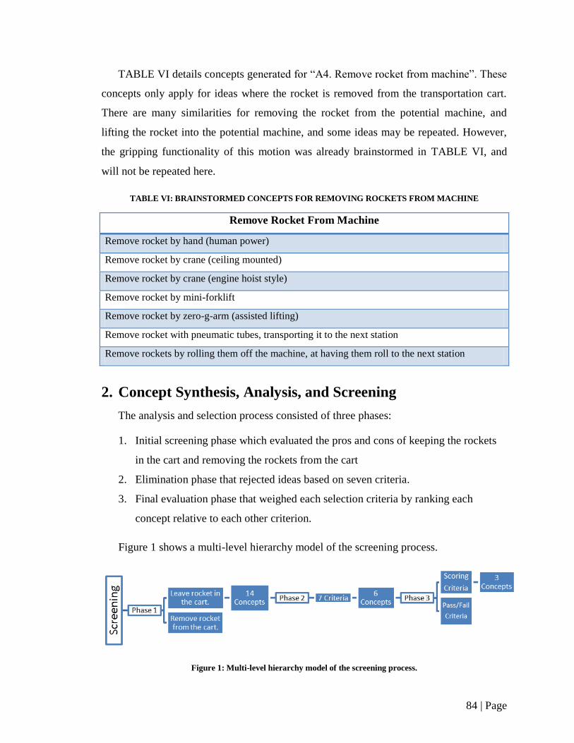
84 | Page
TABLE VI details concepts generated for “A4. Remove rocket from machine”. These
concepts only apply for ideas where the rocket is removed from the transportation cart.
There are many similarities for removing the rocket from the potential machine, and
lifting the rocket into the potential machine, and some ideas may be repeated. However,
the gripping functionality of this motion was already brainstormed in TABLE VI, and
will not be repeated here.
TABLE VI: BRAINSTORMED CONCEPTS FOR REMOVING ROCKETS FROM MACHINE
Remove Rocket From Machine
Remove rocket by hand (human power)
Remove rocket by crane (ceiling mounted)
Remove rocket by crane (engine hoist style)
Remove rocket by mini-forklift
Remove rocket by zero-g-arm (assisted lifting)
Remove rocket with pneumatic tubes, transporting it to the next station
Remove rockets by rolling them off the machine, at having them roll to the next station
2. Concept Synthesis, Analysis, and Screening
The analysis and selection process consisted of three phases:
1. Initial screening phase which evaluated the pros and cons of keeping the rockets
in the cart and removing the rockets from the cart
2. Elimination phase that rejected ideas based on seven criteria.
3. Final evaluation phase that weighed each selection criteria by ranking each
concept relative to each other criterion.
Figure 1 shows a multi-level hierarchy model of the screening process.
Figure 1: Multi-level hierarchy model of the screening process.
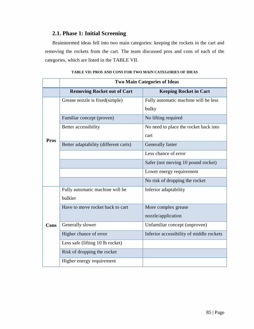
85 | Page
2.1. Phase 1: Initial Screening
Brainstormed ideas fell into two main categories: keeping the rockets in the cart and
removing the rockets from the cart. The team discussed pros and cons of each of the
categories, which are listed in the TABLE VII.
TABLE VII: PROS AND CONS FOR TWO MAIN CATEGORIES OF IDEAS
Two Main Categories of Ideas
Removing Rocket out of Cart Keeping Rocket in Cart
Pros
Grease nozzle is fixed(simple) Fully automatic machine will be less
bulky
Familiar concept (proven) No lifting required
Better accessibility No need to place the rocket back into
cart
Better adaptability (different carts) Generally faster
Less chance of error
Safer (not moving 10 pound rocket)
Lower energy requirement
No risk of dropping the rocket
Cons
Fully automatic machine will be
bulkier
Inferior adaptability
Have to move rocket back to cart More complex grease
nozzle/application
Generally slower Unfamiliar concept (unproven)
Higher chance of error Inferior accessibility of middle rockets
Less safe (lifting 10 lb rocket)
Risk of dropping the rocket
Higher energy requirement

86 | Page
Since ‘Keeping Rocket in the Cart’ idea reduced the amount of handling by the
operator and had a higher number of pros and lower number of cons compared to the
alternative idea of ‘Removing Rocket from the Cart’, the team concluded that keeping the
rocket in the cart is the desirable option.
2.2. Phase 2: Elimination
Concepts that required removal of the rocket from the cart were eliminated in Phase
1. Fourteen concepts were analyzed in Phase 2. In Section 1.2.1, keeping the rocket in the
cart was divided into two key functions of indexing the rockets (or the cart) and grease
application. Since indexing is dependent on the grease application method, the team
decided to screen the concepts based on the grease application method alone.
The team decided on seven criteria which were used to analyze each concept using a
screening matrix. These criteria were cost, manufacturability of the design, reliability of
the design, number of steps involved in the process, speed of the process, grease
application quality, and physical work by the operator. Each concept was given either a
‘1’ for a better effect, ‘-1’ for a worse effect, or ‘0’ for a same effect on each of the
criteria when compared to the reference concept, “Nozzle rotating on a shaft”. The team
decided to fill the screening matrix individually which ensured independent and equal
opinion from each team member. These values were then averaged and given a final
score. A concept with a score of ‘-1’ or less was immediately eliminated. A concept
scoring between ‘-1’ and ‘0’ was subject to team discussion and a score of ‘0’ or greater
was approved. The following TABLE VIII is the screening matrix with individual and
average scores of the team.
Concepts requiring team discussion were multi nozzle (stationary), wheel clamp
spinning rocket (from top), the external circular track, and the corkscrew rotating nozzle.
The multi nozzle (stationary) and wheel clamp spinning rocket concepts were eliminated
as the team felt the concepts did not have enough positive traits. The corkscrew rotating
nozzle concept was eliminated as the team felt it was too complex. Finally the external
circular track was chosen to move forward, as although it had a negative score, the team
felt the concept had a very high potential.
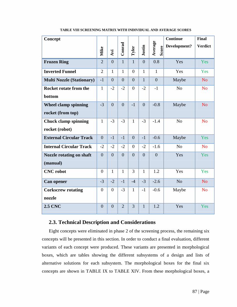
87 | Page
TABLE VIII SCREENING MATRIX WITH INDIVIDUAL AND AVERAGE SCORES
Concept
Mik
e
Avi
Con
rad
Tyle
r
Ju
stin
Avera
ge
Sco
re
Continue
Development?
Final
Verdict
Frozen Ring 2 0 1 1 0 0.8 Yes Yes
Inverted Funnel 2 1 1 0 1 1 Yes Yes
Multi Nozzle (Stationary) -1 0 0 0 1 0 Maybe No
Rocket rotate from the
bottom
1 -2 -2 0 -2 -1 No No
Wheel clamp spinning
rocket (from top)
-3 0 0 -1 0 -0.8 Maybe No
Chuck clamp spinning
rocket (robot)
1 -3 -3 1 -3 -1.4 No No
External Circular Track 0 -1 -1 0 -1 -0.6 Maybe Yes
Internal Circular Track -2 -2 -2 0 -2 -1.6 No No
Nozzle rotating on shaft
(manual)
0 0 0 0 0 0 Yes Yes
CNC robot 0 1 1 3 1 1.2 Yes Yes
Can opener -3 -2 -1 -4 -3 -2.6 No No
Corkscrew rotating
nozzle
0 0 -3 1 -1 -0.6 Maybe No
2.5 CNC 0 0 2 3 1 1.2 Yes Yes
2.3. Technical Description and Considerations
Eight concepts were eliminated in phase 2 of the screening process, the remaining six
concepts will be presented in this section. In order to conduct a final evaluation, different
variants of each concept were produced. These variants are presented in morphological
boxes, which are tables showing the different subsystems of a design and lists of
alternative solutions for each subsystem. The morphological boxes for the final six
concepts are shown in TABLE IX to TABLE XIV. From these morphological boxes, a
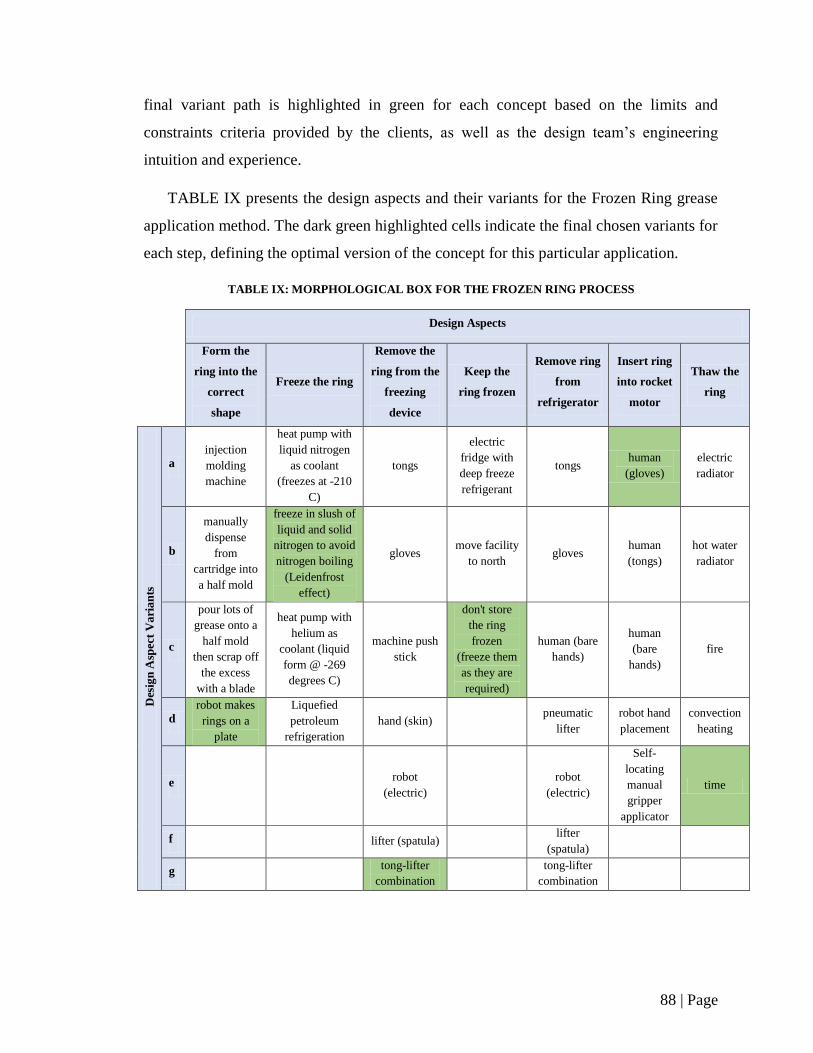
88 | Page
final variant path is highlighted in green for each concept based on the limits and
constraints criteria provided by the clients, as well as the design team’s engineering
intuition and experience.
TABLE IX presents the design aspects and their variants for the Frozen Ring grease
application method. The dark green highlighted cells indicate the final chosen variants for
each step, defining the optimal version of the concept for this particular application.
TABLE IX: MORPHOLOGICAL BOX FOR THE FROZEN RING PROCESS
Design Aspects
Form the
ring into the
correct
shape
Freeze the ring
Remove the
ring from the
freezing
device
Keep the
ring frozen
Remove ring
from
refrigerator
Insert ring
into rocket
motor
Thaw the
ring
Des
ign
Asp
ect
Va
ria
nts
a
injection
molding
machine
heat pump with
liquid nitrogen
as coolant
(freezes at -210
C)
tongs
electric
fridge with
deep freeze
refrigerant
tongs human
(gloves)
electric
radiator
b
manually
dispense
from
cartridge into
a half mold
freeze in slush of
liquid and solid
nitrogen to avoid
nitrogen boiling
(Leidenfrost
effect)
gloves move facility
to north gloves
human
(tongs)
hot water
radiator
c
pour lots of
grease onto a
half mold
then scrap off
the excess
with a blade
heat pump with
helium as
coolant (liquid
form @ -269
degrees C)
machine push
stick
don't store
the ring
frozen
(freeze them
as they are
required)
human (bare
hands)
human
(bare
hands)
fire
d
robot makes
rings on a
plate
Liquefied
petroleum
refrigeration
hand (skin)
pneumatic
lifter
robot hand
placement
convection
heating
e
robot
(electric)
robot
(electric)
Self-
locating
manual
gripper
applicator
time
f
lifter (spatula)
lifter
(spatula)
g
tong-lifter
combination
tong-lifter
combination
89 | Page
For the concept variant selection shown in TABLE IX, technical considerations
moving forward include either purchasing or designing a CNC dispensing mechanism to
create grease rings on a cooling tray. If designed, this would include design analysis for
lead screws to control horizontal translation, motor specifications to provide adequate
power to the robot applicator, a control system to govern the robot movement, specifying
recirculating ball bearings for the horizontal applicator table to traverse the lead screws,
and a gear pump or other mechanism to control grease flow. For the cooling method,
thermodynamic analysis would need to be conducted for the requirements of the coolant,
compressor, and pump involved in the refrigerating system. This would be done
simultaneously with a heat transfer analysis on the cooling tray and grease rings to
determine the cooling system heat flux requirements. Research and experiments have
shown that the extreme cooling to the grease will not inhibit its function [8]. Finally, heat
transfer analysis would need to be completed on the grease rings to determine how long
is required to return the frozen rings back to room temperature once they are seated in a
rocket motor.
TABLE X presents the design aspects and their variants for the Circular Track grease
application method. The dark green highlighted cells indicate the final chosen variants for
each step, defining the optimal version of the concept for this particular application.
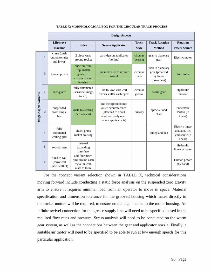
90 | Page
TABLE X: MORPHOLOGICAL BOX FOR THE CIRCULAR TRACK PROCESS
Design Aspects
Lift/move
machine Index Grease Applicator
Track
Style
Track Rotation
Method
Rotation
Power Source
Des
ign
Asp
ect
Va
ria
nts
a
crane (push
button to raise
and lower)
2 piece wrap
around rocket
cartridge on applicator
(no line)
circular
bearing
gear to planetary
gear Electric motor
b human power
slide on from
top, match
groove to
circular rocket
housing
line moves up to infinite
swivel
circular
rack
rack to planetary
gear (powered
by linear
movement)
Air motor
c zero-g arm
fully automated
- sensors (image,
touch)
line follows cart, cart
reverses after each cycle
circular
groove worm gear
Hydraulic
motor?
d
suspended
from single
line
mate to existing
parts on cart
line incorporated into
outer circumference
(attached to donut
reservoir, only open
where applicator is)
railway sprocket and
chain
Pneumatic
Piston (if
linear)
e
fully
automated
ceiling grid
chuck grabs
rocket housing pulley and belt
Electric linear
actuator, i.e.
lead screw (if
linear)
f robotic arm
internal
expanding
interface
Hydraulic
linear actuator
g
fixed to wall
(move cart
underneath it)
add four index
pins around each
rocket in cart,
mate to these
Human power
(by hand)
For the concept variant selection shown in TABLE X, technical considerations
moving forward include conducting a static force analysis on the suspended zero gravity
arm to ensure it requires minimal load from an operator to move in space. Material
specification and dimension tolerance for the grooved housing which mates directly to
the rocket motors will be required, to ensure no damage is done to the motor housing. An
infinite swivel connection for the grease supply line will need to be specified based in the
required flow rates and pressure. Stress analysis will need to be conducted on the worm
gear system, as well as the connections between the gear and applicator nozzle. Finally, a
suitable air motor will need to be specified to be able to run at low enough speeds for this
particular application.

91 | Page
TABLE XI presents the design aspects and their variants for the Inverted Funnel
grease application method. The dark green highlighted cells indicate the final chosen
variants for each step, defining the optimal version of the concept for this particular
application.
TABLE XI: MORPHOLOGICAL BOX FOR THE INVERTED FUNNEL PROCESS
Design Aspects
Move cart
into
position
Secure cart X-Y
translation
Locate
rocket
Nozzle
movement
(z-axis)
Z-axis
position
control
Grease
feed
Dispense
grease
Des
ign
Asp
ect
Va
ria
nts
a worker
pushes cart
fold arms
down
(manual)
manual manual
electric
motor and
lead screw
physical
switch cartridge pneumatic
b conveyor
belt
pneumatic
arms
pneumatic
piston and
rack with
pinion
laser
sensors
pneumatic
piston
photo
sensor
straight
from pail
screw
pump
c
hydraulic
arms
hydraulic
piston and
rack with
pinion
photo
sensors
hydraulic
piston
laser
sensor
d
electric
arms
electric motor
and lead screw
For the concept variant selection shown in TABLE XI, technical considerations
moving forward include determining the dimensional tolerance for the securing
mechanism between the pneumatic arms and the cart. The design of the automated
components include stress analysis for lead screws to control horizontal translation,
motor specifications to provide adequate power to the robot applicator, a control system
to govern the robot movement, specifying recirculating ball bearings for the horizontal
applicator table to traverse the lead screws, and a gear pump or other mechanism to
control grease flow.
TABLE XII presents the design aspects and their variants for the Rotating Nozzle
Shaft grease application method. The dark green highlighted cells indicate the final
chosen variants for each step, defining the optimal version of the concept for this
particular application.
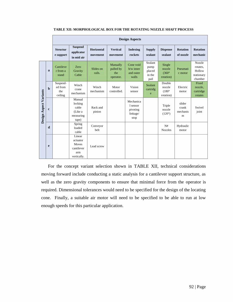
92 | Page
TABLE XII: MORPHOLOGICAL BOX FOR THE ROTATING NOZZLE SHAFT PROCESS
Design Aspects
Structur
e support
Suspend
applicator
in mid air
Horizontal
movement
Vertical
movement
Indexing
rockets
Supply
sealant
Dispense
sealant
Rotation
of nozzle
Rotation
mechanic
Des
ign
Asp
ect
Va
ria
nts
a Cantileve
r from a
stand
Zero
Gravity
Cable
Slides on
rails.
Manually
pulled by
the
operator.
Cone void
b/w inner
and outer
walls
Sealant
pump
placed
in the
pail
Single
nozzle
(360°
rotation)
Pneumati
c motor
Nozzle
rotates,
Hollow
stationary
chamber
b
Suspend-
ed from
the
ceiling
Winch
crane
mechanism
Winch
mechanism
Motor
controlled.
Vision
sensor
Sealant
cartridg
e
Double
nozzle
(180°
rotation)
Electric
motor
Fixed
nozzle,
cartridge
rotates
c
Manual
locking
cable
(Like a
measuring
tape)
Rack and
pinion
Mechanica
l sensor
pivoting
linkage/
stop
Triple
nozzle
(120°)
slider
crank
mechanis
m
Swivel
joint
d
Spring
loaded
cable
Conveyor
belt
N#
Nozzles
Hydraulic
motor
e
Linear
actuator
Moves
cantilever
arm
vertically.
Lead screw
For the concept variant selection shown in TABLE XII, technical considerations
moving forward include conducting a static analysis for a cantilever support structure, as
well as the zero gravity components to ensure that minimal force from the operator is
required. Dimensional tolerances would need to be specified for the design of the locating
cone. Finally, a suitable air motor will need to be specified to be able to run at low
enough speeds for this particular application.

93 | Page
TABLE XIII presents the design aspects and their variants for the Robot Arm grease
application method. The dark green highlighted cells indicate the final chosen variants for
each step, defining the optimal version of the concept for this particular application.
TABLE XIII: MORPHOLOGICAL BOX FOR THE ROBOT ARM PROCESS
Design Aspects
Power
source Sensors
End
effector
Robotic
joints
Physical
configuration
Control
system
Degrees
of
freedom
Indexing
Des
ign
Asp
ect
Va
ria
nts
a Hydraulic Position
Grease /
Sealant
Applicator
Nozzle
Prismatic Cartesian
Point-to-
Point
(PTP)
1 DOF
Lock cart
into a
predestinate
d location
b
Electric-
Stepper
Motor
Range
Revolute Cylindrical Continuous
Path (CP) 2 DOF
Have
sensor
locate each
rocket
individually
c
Electric-
Servo
Motor
Velocity
Combo Polar Controlled-
path 3 DOF
d Pneumatic Proximity
Jointed-Arm
4 DOF
e
Acoustic
5 DOF
f
Touch
6 DOF
g
Force
For the concept variant selection shown in TABLE XIII, it is likely that the
recommended option is to purchase a pre-fabricated robot arm. Technical considerations
moving forward include determining the required workspace dimensions needed to
complete the process, the maximum load demand that would be put on the robot arm, as
well as the level of feedback sensors. These factors are required in order to specify an
appropriate robot arm for purchase.
TABLE XIV presents the design aspects and their variants for the 2.5D CNC grease
application method. The dark green highlighted cells indicate the final chosen variants for
each step, defining the optimal version of the concept for this particular application.
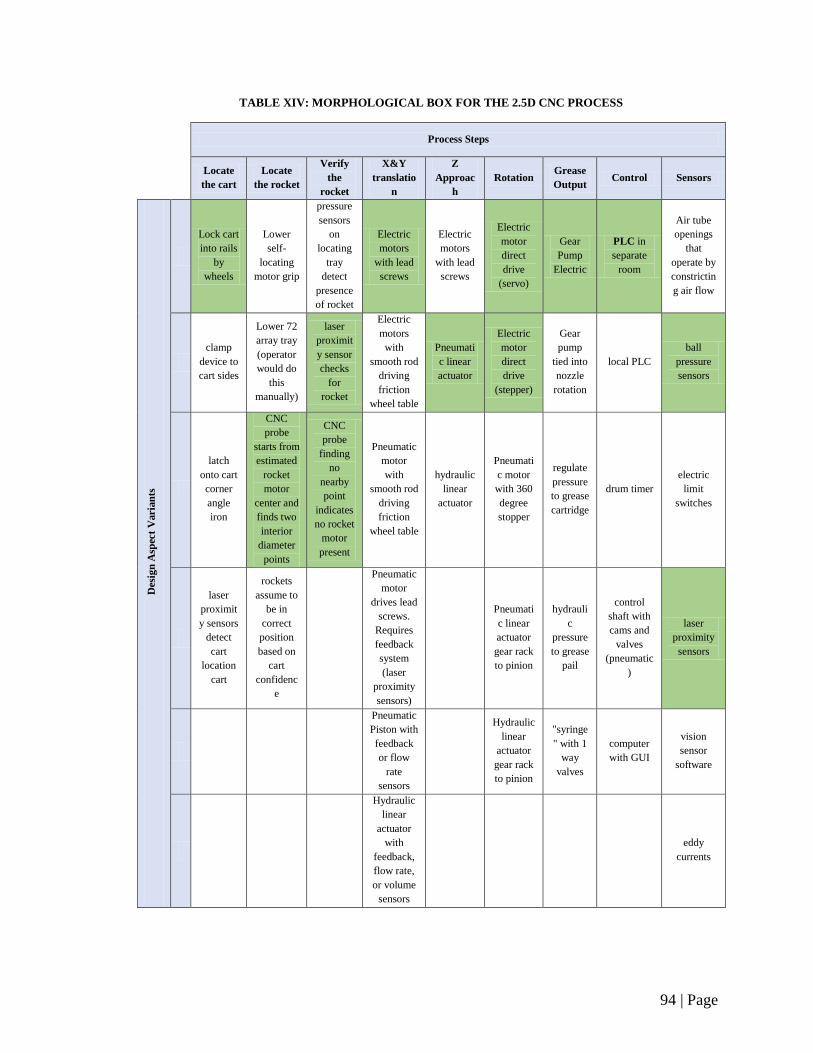
94 | Page
TABLE XIV: MORPHOLOGICAL BOX FOR THE 2.5D CNC PROCESS
Process Steps
Locate
the cart
Locate
the rocket
Verify
the
rocket
X&Y
translatio
n
Z
Approac
h
Rotation Grease
Output Control Sensors
Des
ign
Asp
ect
Vari
an
ts
a
Lock cart
into rails
by
wheels
Lower
self-
locating
motor grip
pressure
sensors
on
locating
tray
detect
presence
of rocket
Electric
motors
with lead
screws
Electric
motors
with lead
screws
Electric
motor
direct
drive
(servo)
Gear
Pump
Electric
PLC in
separate
room
Air tube
openings
that
operate by
constrictin
g air flow
b
clamp
device to
cart sides
Lower 72
array tray
(operator
would do
this
manually)
laser
proximit
y sensor
checks
for
rocket
Electric
motors
with
smooth rod
driving
friction
wheel table
Pneumati
c linear
actuator
Electric
motor
direct
drive
(stepper)
Gear
pump
tied into
nozzle
rotation
local PLC
ball
pressure
sensors
c
latch
onto cart
corner
angle
iron
CNC
probe
starts from
estimated
rocket
motor
center and
finds two
interior
diameter
points
CNC
probe
finding
no
nearby
point
indicates
no rocket
motor
present
Pneumatic
motor
with
smooth rod
driving
friction
wheel table
hydraulic
linear
actuator
Pneumati
c motor
with 360
degree
stopper
regulate
pressure
to grease
cartridge
drum timer
electric
limit
switches
d
laser
proximit
y sensors
detect
cart
location
cart
rockets
assume to
be in
correct
position
based on
cart
confidenc
e
Pneumatic
motor
drives lead
screws.
Requires
feedback
system
(laser
proximity
sensors)
Pneumati
c linear
actuator
gear rack
to pinion
hydrauli
c
pressure
to grease
pail
control
shaft with
cams and
valves
(pneumatic
)
laser
proximity
sensors
e
Pneumatic
Piston with
feedback
or flow
rate
sensors
Hydraulic
linear
actuator
gear rack
to pinion
"syringe
" with 1
way
valves
computer
with GUI
vision
sensor
software
f
Hydraulic
linear
actuator
with
feedback,
flow rate,
or volume
sensors
eddy
currents
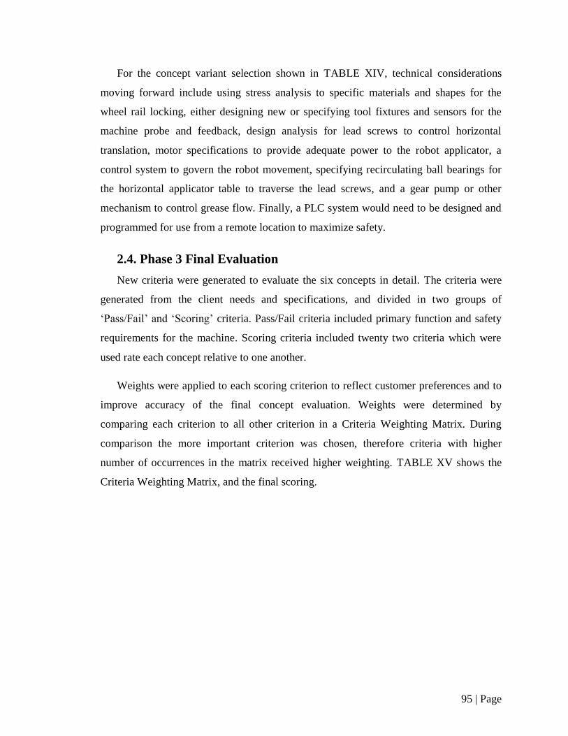
95 | Page
For the concept variant selection shown in TABLE XIV, technical considerations
moving forward include using stress analysis to specific materials and shapes for the
wheel rail locking, either designing new or specifying tool fixtures and sensors for the
machine probe and feedback, design analysis for lead screws to control horizontal
translation, motor specifications to provide adequate power to the robot applicator, a
control system to govern the robot movement, specifying recirculating ball bearings for
the horizontal applicator table to traverse the lead screws, and a gear pump or other
mechanism to control grease flow. Finally, a PLC system would need to be designed and
programmed for use from a remote location to maximize safety.
2.4. Phase 3 Final Evaluation
New criteria were generated to evaluate the six concepts in detail. The criteria were
generated from the client needs and specifications, and divided in two groups of
‘Pass/Fail’ and ‘Scoring’ criteria. Pass/Fail criteria included primary function and safety
requirements for the machine. Scoring criteria included twenty two criteria which were
used rate each concept relative to one another.
Weights were applied to each scoring criterion to reflect customer preferences and to
improve accuracy of the final concept evaluation. Weights were determined by
comparing each criterion to all other criterion in a Criteria Weighting Matrix. During
comparison the more important criterion was chosen, therefore criteria with higher
number of occurrences in the matrix received higher weighting. TABLE XV shows the
Criteria Weighting Matrix, and the final scoring.

96 | Page
TABLE XV: CRITERIA WEIGHTING MATRIX
safe
to
op
erat
e
grea
se o
utp
ut
regl
uat
ale
and
ver
ifab
le
# ro
cket
s gr
ease
d b
efo
re g
reas
e re
fill
con
sist
ent
and
co
rrec
t b
ead
siz
e/sp
acin
g
air
po
cket
s
acco
mo
dat
ion
s fo
r p
eop
le o
f va
ryin
g h
eigh
t
ove
rall
mac
hin
e re
liab
lilit
y
risk
of
dam
age
to
ro
cket
adap
tab
ility
(c1
7, f
utu
re)
easy
to
set
up
an
d o
per
ate
leve
l of
op
erat
or
trai
nin
g re
qu
ired
ph
ysic
al w
ork
of
op
erat
or
amo
un
t o
f o
per
ato
r h
and
ling
& in
terv
enti
on
ease
of
mai
nte
nan
ce
freq
uen
cy o
f m
ain
ten
ance
setu
p t
ime
op
erat
ion
tim
e
des
ign
co
mp
lexi
ty
man
ufa
ctu
rin
g/p
urc
has
ing
cost
Op
erat
ion
Co
st
Mai
nte
nan
ce c
ost
Mac
hin
e Fo
otp
rin
t
A B C D E F G H I J K L M N O P Q R S T U V
A safe to operate A A A A A A A A A A A A A A A A A A A A A
Bgrease output regulated
and verifiableB D E B B H B B B L M B O B Q B B B B B
C# rockets greased before
grease refillD E C G H C J C L M C O P Q C S T C C
Dconsistent & correct
bead size/spacingD D D H D D D D D D D D D D D D D D
E air pockets E E H E E E E E E O E E E E E E E
Faccomodations for
people of varying heightG H F J F L M N O P Q R S T U F
G overall machine reliablility H G J G L M G G P Q G G T G G
H risk of damage to rocket H H H H H H H H H H H H H H
I adaptability (c17, future) J I L M N O P Q I S T U I
J easy to setup and operate J J M J J P Q J J T J J
Klevel of operator training
requiredL M N O P Q R S T U K
L physical work of operator L L L P Q L L T L L
M
amount of operator
handling
& intervention
M M P Q M M T M M
N ease of maintenance O P Q N S T U N
O frequency of maintenance P Q O O T U O
P setup time Q P P T P P
Q operation time Q Q T Q Q
R design complexity S T U R
Smanufacturing &
purchasing costT S S
T Operation Cost T T
U Maintenance cost U
V Machine Footprint
21 13 7 19 17 3 10 20 3 12 1 13 13 5 10 14 16 3 8 16 7 00.09 0.06 0.03 0.08 0.07 0.01 0.04 0.09 0.01 0.05 0.00 0.06 0.06 0.02 0.04 0.06 0.07 0.01 0.03 0.07 0.03 0.00
0.91 0.56 0.30 0.82 0.74 0.13 0.43 0.87 0.13 0.52 0.04 0.56 0.56 0.22 0.43 0.61 0.69 0.13 0.35 0.69 0.30 0.00
Criteria
Total number of Hits
Weightings
Weightings multiplied by ten
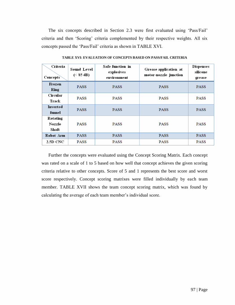
97 | Page
The six concepts described in Section 2.3 were first evaluated using ‘Pass/Fail’
criteria and then ‘Scoring’ criteria complemented by their respective weights. All six
concepts passed the ‘Pass/Fail’ criteria as shown in TABLE XVI.
TABLE XVI: EVALUATION OF CONCEPTS BASED ON PASS/FAIL CRITERIA
Further the concepts were evaluated using the Concept Scoring Matrix. Each concept
was rated on a scale of 1 to 5 based on how well that concept achieves the given scoring
criteria relative to other concepts. Score of 5 and 1 represents the best score and worst
score respectively. Concept scoring matrixes were filled individually by each team
member. TABLE XVII shows the team concept scoring matrix, which was found by
calculating the average of each team member’s individual score.
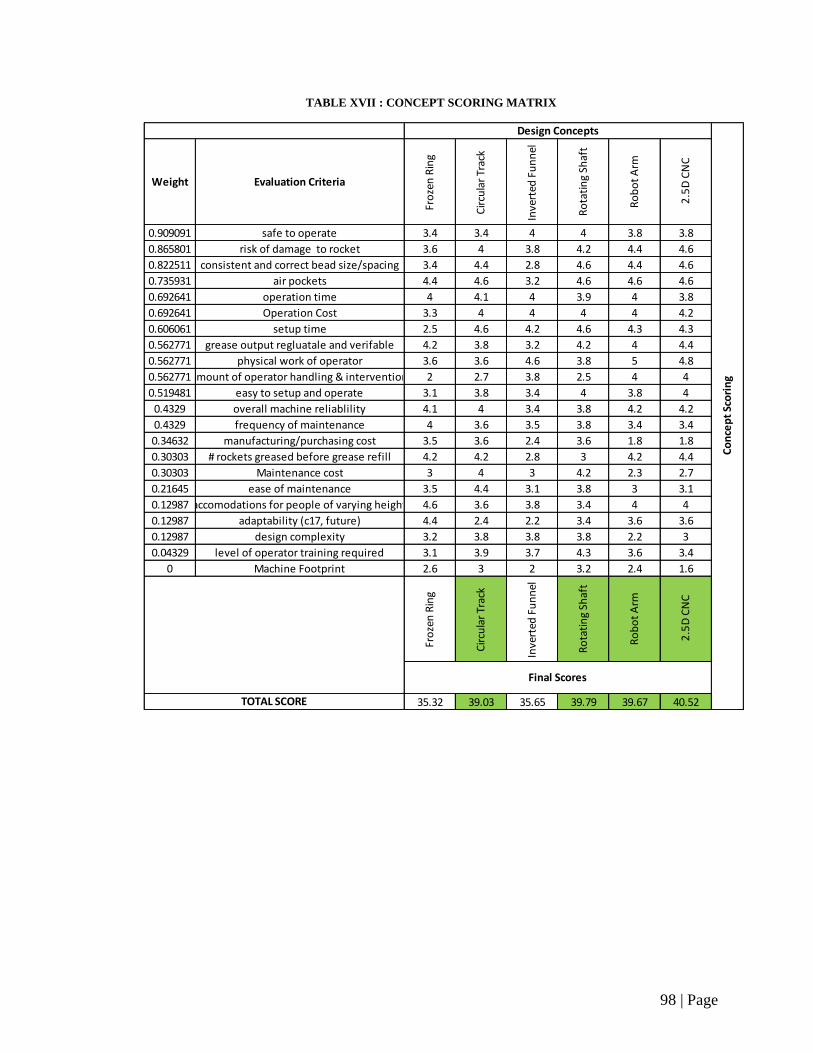
98 | Page
TABLE XVII : CONCEPT SCORING MATRIX
Weight Evaluation Criteria
Fro
zen
Rin
g
Cir
cula
r Tr
ack
Inve
rted
Fu
nn
el
Ro
tati
ng
Shaf
t
Ro
bo
t A
rm
2.5
D C
NC
0.909091 safe to operate 3.4 3.4 4 4 3.8 3.8
0.865801 risk of damage to rocket 3.6 4 3.8 4.2 4.4 4.6
0.822511 consistent and correct bead size/spacing 3.4 4.4 2.8 4.6 4.4 4.6
0.735931 air pockets 4.4 4.6 3.2 4.6 4.6 4.6
0.692641 operation time 4 4.1 4 3.9 4 3.8
0.692641 Operation Cost 3.3 4 4 4 4 4.2
0.606061 setup time 2.5 4.6 4.2 4.6 4.3 4.3
0.562771 grease output regluatale and verifable 4.2 3.8 3.2 4.2 4 4.4
0.562771 physical work of operator 3.6 3.6 4.6 3.8 5 4.8
0.562771amount of operator handling & intervention 2 2.7 3.8 2.5 4 4
0.519481 easy to setup and operate 3.1 3.8 3.4 4 3.8 4
0.4329 overall machine reliablility 4.1 4 3.4 3.8 4.2 4.2
0.4329 frequency of maintenance 4 3.6 3.5 3.8 3.4 3.4
0.34632 manufacturing/purchasing cost 3.5 3.6 2.4 3.6 1.8 1.8
0.30303 # rockets greased before grease refill 4.2 4.2 2.8 3 4.2 4.4
0.30303 Maintenance cost 3 4 3 4.2 2.3 2.7
0.21645 ease of maintenance 3.5 4.4 3.1 3.8 3 3.1
0.12987 accomodations for people of varying height 4.6 3.6 3.8 3.4 4 4
0.12987 adaptability (c17, future) 4.4 2.4 2.2 3.4 3.6 3.6
0.12987 design complexity 3.2 3.8 3.8 3.8 2.2 3
0.04329 level of operator training required 3.1 3.9 3.7 4.3 3.6 3.4
0 Machine Footprint 2.6 3 2 3.2 2.4 1.6
Fro
zen
Rin
g
Cir
cula
r Tr
ack
Inve
rted
Fu
nn
el
Ro
tati
ng
Shaf
t
Ro
bo
t A
rm
2.5
D C
NC
35.32 39.03 35.65 39.79 39.67 40.52
Co
nce
pt
Sco
rin
g
Design Concepts
TOTAL SCORE
Final Scores
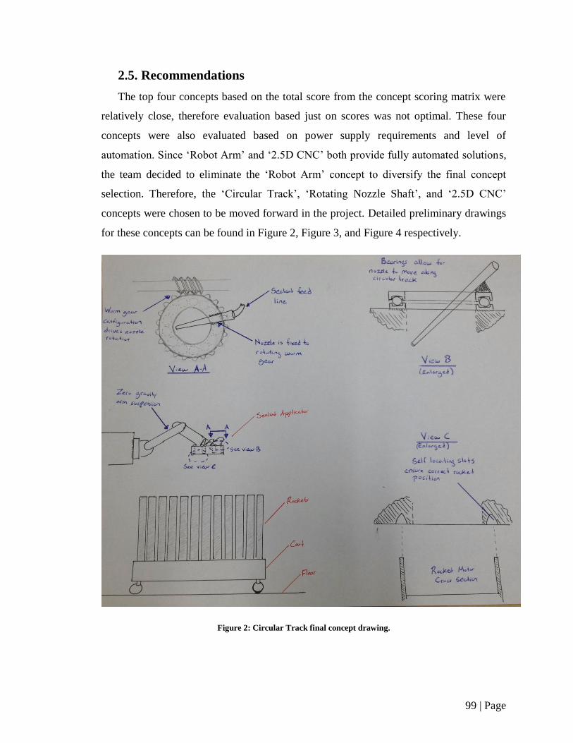
99 | Page
2.5. Recommendations
The top four concepts based on the total score from the concept scoring matrix were
relatively close, therefore evaluation based just on scores was not optimal. These four
concepts were also evaluated based on power supply requirements and level of
automation. Since ‘Robot Arm’ and ‘2.5D CNC’ both provide fully automated solutions,
the team decided to eliminate the ‘Robot Arm’ concept to diversify the final concept
selection. Therefore, the ‘Circular Track’, ‘Rotating Nozzle Shaft’, and ‘2.5D CNC’
concepts were chosen to be moved forward in the project. Detailed preliminary drawings
for these concepts can be found in Figure 2, Figure 3, and Figure 4 respectively.
Figure 2: Circular Track final concept drawing.
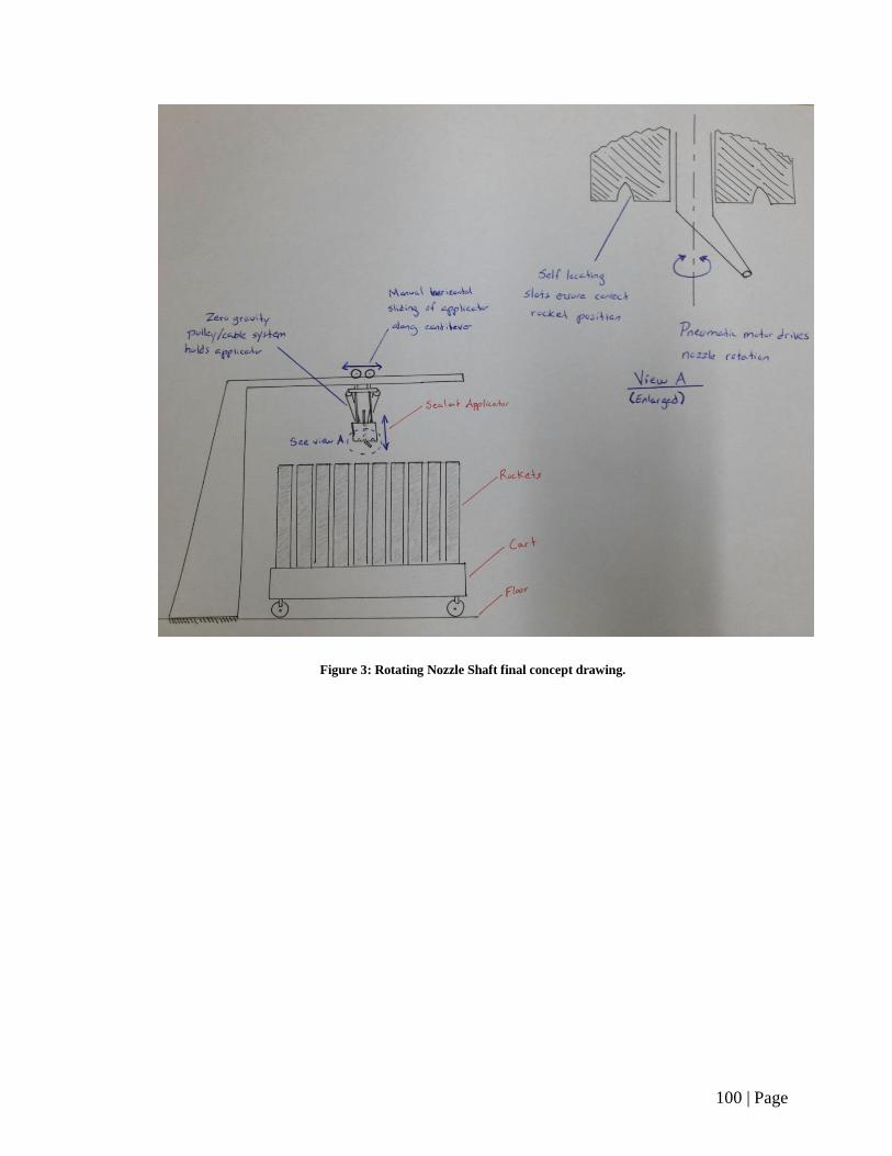
100 | Page
Figure 3: Rotating Nozzle Shaft final concept drawing.
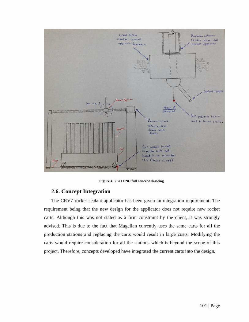
101 | Page
Figure 4: 2.5D CNC full concept drawing.
2.6. Concept Integration
The CRV7 rocket sealant applicator has been given an integration requirement. The
requirement being that the new design for the applicator does not require new rocket
carts. Although this was not stated as a firm constraint by the client, it was strongly
advised. This is due to the fact that Magellan currently uses the same carts for all the
production stations and replacing the carts would result in large costs. Modifying the
carts would require consideration for all the stations which is beyond the scope of this
project. Therefore, concepts developed have integrated the current carts into the design.
102 | Page
Another suggestion from the client was for the design to be integrated into the current
pneumatic system at the Magellan facility. A readily available air supply is present.
Therefore, pneumatics are the ideal means of power since it will reduce initial capital
costs and is safe for use in an explosive environment. Electronic devices are restricted
due to the non-explosive requirement. However explosive proof electronics do exist and
may be used if they comply with the Class 1 Division 1 explosion regulations. Another
alternative which was considered is hydraulics. In concept development all means of
driving the design were considered. Pneumatics were generally strived for and given
higher ranking for criteria based on the suggestion of the air supply integration.
2.7. Concept Fusion
The fusing of concepts took place throughout the concept development. Taking
various ideas and merging them was the means to which the end concepts were arrived at.
Brainstorming lead to the development of many ideas for performing the various tasks
required in the sealant application process. By using the use of morphological boxes the
brainstormed concepts could be considered for fusing into the overall design concepts.
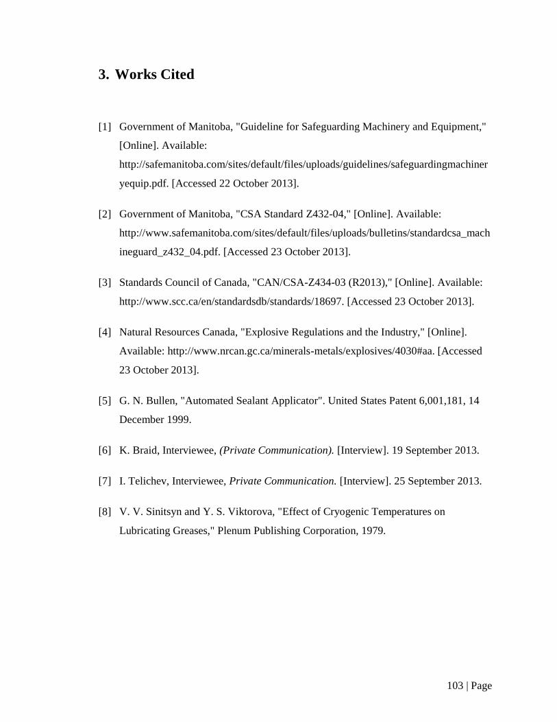
103 | Page
3. Works Cited
[1] Government of Manitoba, "Guideline for Safeguarding Machinery and Equipment,"
[Online]. Available:
http://safemanitoba.com/sites/default/files/uploads/guidelines/safeguardingmachiner
yequip.pdf. [Accessed 22 October 2013].
[2] Government of Manitoba, "CSA Standard Z432-04," [Online]. Available:
http://www.safemanitoba.com/sites/default/files/uploads/bulletins/standardcsa_mach
ineguard_z432_04.pdf. [Accessed 23 October 2013].
[3] Standards Council of Canada, "CAN/CSA-Z434-03 (R2013)," [Online]. Available:
http://www.scc.ca/en/standardsdb/standards/18697. [Accessed 23 October 2013].
[4] Natural Resources Canada, "Explosive Regulations and the Industry," [Online].
Available: http://www.nrcan.gc.ca/minerals-metals/explosives/4030#aa. [Accessed
23 October 2013].
[5] G. N. Bullen, "Automated Sealant Applicator". United States Patent 6,001,181, 14
December 1999.
[6] K. Braid, Interviewee, (Private Communication). [Interview]. 19 September 2013.
[7] I. Telichev, Interviewee, Private Communication. [Interview]. 25 September 2013.
[8] V. V. Sinitsyn and Y. S. Viktorova, "Effect of Cryogenic Temperatures on
Lubricating Greases," Plenum Publishing Corporation, 1979.

104 | Page
Appendix B

105 | Page
Table of Contents – Appendix B
List of Tables ............................................................................................................ 106
1. Preliminary Cost Analysis ............................................................................... 107
2. Final Design Economic Feasibility .................................................................. 112
2.1. Single Sealant Applicator Economic Calculations ................................... 112
2.2. Dual Sealant Applicator Economic Calculations ...................................... 115
3. Works Cited ..................................................................................................... 120
106 | Page
List of Tables
TABLE I: 2.5 CNC PRELIMINARY COST ESTIMATE ............................................. 107
TABLE II: CIRCULAR TRACK PRELIMINARY COST ESTIMATE ....................... 108
TABLE III: ROTATING NOZZLE PRELIMINARY COST ANALYSIS ................... 109
TABLE IV: COMERCIALLY AVAILABLE TORQUE REACTION ARM
PRELIMINARY COST ESTIMATE ............................................................................. 110
TABLE V: CUSTOM MANUFACTURED TORQUE REACTION ARM
PRELIMINARY COST ESTIMATE ............................................................................. 110
TABLE VI: TOOL BALANCER PRELIMINARY COST ESTIMATE ....................... 111
TABLE VII: PRELIMINARY COST ANALYSIS SUMMARY .................................. 111
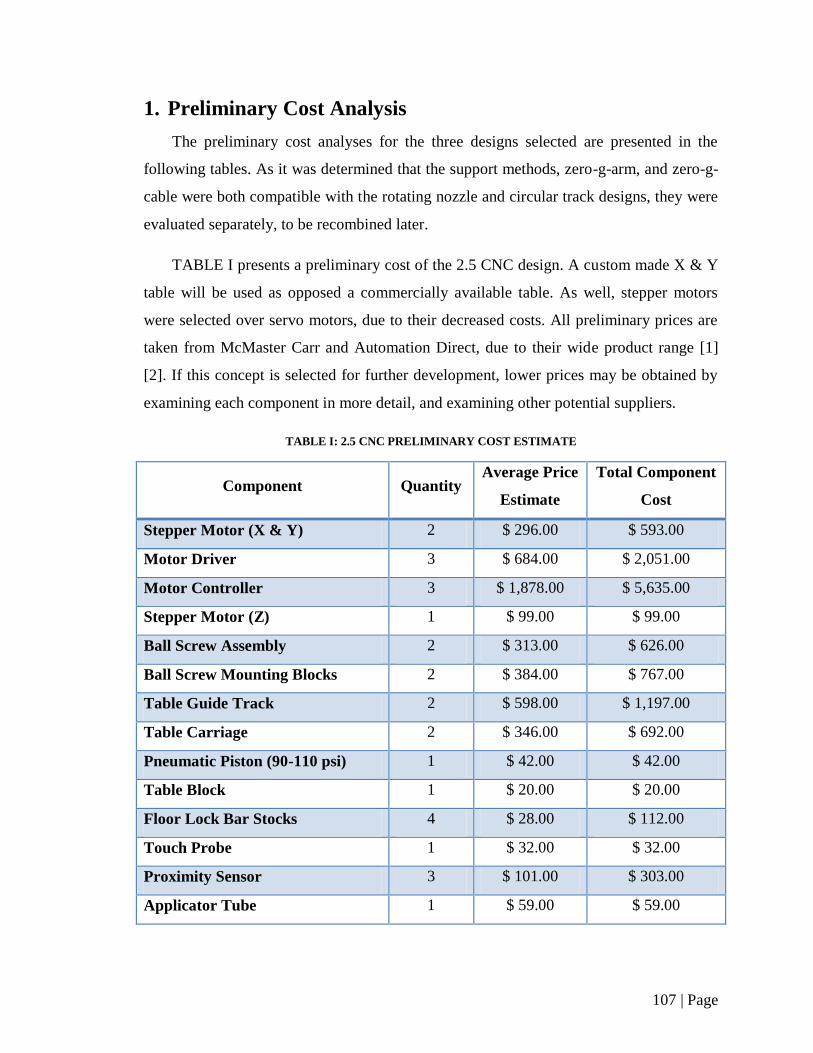
107 | Page
1. Preliminary Cost Analysis
The preliminary cost analyses for the three designs selected are presented in the
following tables. As it was determined that the support methods, zero-g-arm, and zero-g-
cable were both compatible with the rotating nozzle and circular track designs, they were
evaluated separately, to be recombined later.
TABLE I presents a preliminary cost of the 2.5 CNC design. A custom made X & Y
table will be used as opposed a commercially available table. As well, stepper motors
were selected over servo motors, due to their decreased costs. All preliminary prices are
taken from McMaster Carr and Automation Direct, due to their wide product range [1]
[2]. If this concept is selected for further development, lower prices may be obtained by
examining each component in more detail, and examining other potential suppliers.
TABLE I: 2.5 CNC PRELIMINARY COST ESTIMATE
Component Quantity Average Price
Estimate
Total Component
Cost
Stepper Motor (X & Y) 2 $ 296.00 $ 593.00
Motor Driver 3 $ 684.00 $ 2,051.00
Motor Controller 3 $ 1,878.00 $ 5,635.00
Stepper Motor (Z) 1 $ 99.00 $ 99.00
Ball Screw Assembly 2 $ 313.00 $ 626.00
Ball Screw Mounting Blocks 2 $ 384.00 $ 767.00
Table Guide Track 2 $ 598.00 $ 1,197.00
Table Carriage 2 $ 346.00 $ 692.00
Pneumatic Piston (90-110 psi) 1 $ 42.00 $ 42.00
Table Block 1 $ 20.00 $ 20.00
Floor Lock Bar Stocks 4 $ 28.00 $ 112.00
Touch Probe 1 $ 32.00 $ 32.00
Proximity Sensor 3 $ 101.00 $ 303.00
Applicator Tube 1 $ 59.00 $ 59.00

108 | Page
TABLE I: 2.5 CNC PRELIMINARY COST ESTIMATE CONTINUED
Component Quantity Average Price
Estimate
Total Component
Cost
Programmable Logic Controller 1 $ 361.00 $ 361.00
Push Buttons 2 $ 24.00 $ 47.00
TOTAL $ 12,634.00
TABLE II presents a preliminary cost for the circular track design. A wormgear
drive was selected to rotate the track, due to its high reduction ratio. This allowed for the
use of a higher speed, and less expensive pneumatic motor. All preliminary prices are
taken from McMaster Carr due to the wide product range offered [1]. As before, if this
concept is selected for further development, lower prices may be obtained by examining
each component in more detail, and examining other potential suppliers.
TABLE II: CIRCULAR TRACK PRELIMINARY COST ESTIMATE
Component Quantity Average Price
Estimate
Total Component
Cost
Turntable 1 $ 8.00 $ 8.00
Wormgear 1 $ 110.00 $ 110.00
Worm 1 $ 30.00 $ 30.00
Pneumatic Motor 1 $ 950.00 $ 950.00
Motor Mount 1 $ 115.00 $ 115.00
Grease Line Swivel 1 $ 32.00 $ 32.00
Grease Hose Connectors 2 $ 13.50 $ 27.00
Grease line/ Nozzle (ft) 1 $ 0.50 $ 0.50
Air Line Connector sets 4 $ 14.50 $ 58.00
Air Lines (ft) 20 $ 1.30 $ 25.80
Air filter/ Regulator 1 $ 155.00 $ 155.00
Indexing Base stock 1 $ 25.00 $ 25.00
Handle 2 $ 12.00 $ 24.00
TOTAL $ 1,560.30
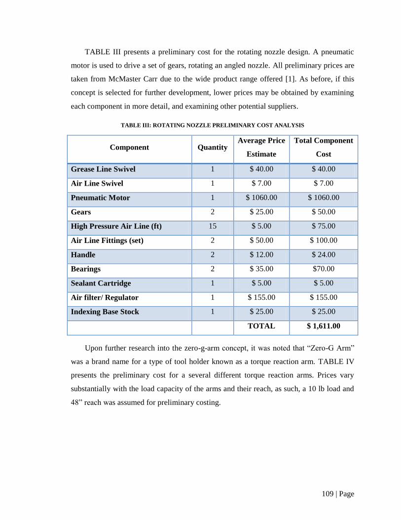
109 | Page
TABLE III presents a preliminary cost for the rotating nozzle design. A pneumatic
motor is used to drive a set of gears, rotating an angled nozzle. All preliminary prices are
taken from McMaster Carr due to the wide product range offered [1]. As before, if this
concept is selected for further development, lower prices may be obtained by examining
each component in more detail, and examining other potential suppliers.
TABLE III: ROTATING NOZZLE PRELIMINARY COST ANALYSIS
Component Quantity Average Price
Estimate
Total Component
Cost
Grease Line Swivel 1 $ 40.00 $ 40.00
Air Line Swivel 1 $ 7.00 $ 7.00
Pneumatic Motor 1 $ 1060.00 $ 1060.00
Gears 2 $ 25.00 $ 50.00
High Pressure Air Line (ft) 15 $ 5.00 $ 75.00
Air Line Fittings (set) 2 $ 50.00 $ 100.00
Handle 2 $ 12.00 $ 24.00
Bearings 2 $ 35.00 $70.00
Sealant Cartridge 1 $ 5.00 $ 5.00
Air filter/ Regulator 1 $ 155.00 $ 155.00
Indexing Base Stock 1 $ 25.00 $ 25.00
TOTAL $ 1,611.00
Upon further research into the zero-g-arm concept, it was noted that “Zero-G Arm”
was a brand name for a type of tool holder known as a torque reaction arm. TABLE IV
presents the preliminary cost for a several different torque reaction arms. Prices vary
substantially with the load capacity of the arms and their reach, as such, a 10 lb load and
48” reach was assumed for preliminary costing.
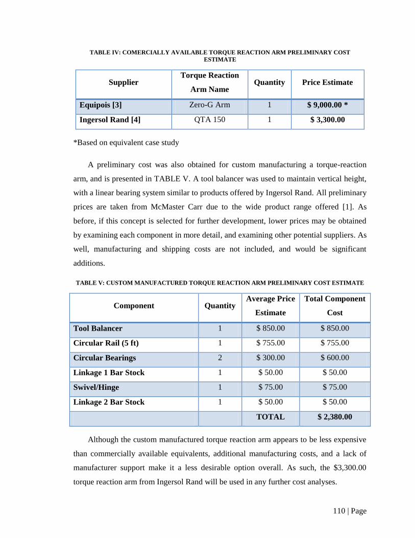
110 | Page
TABLE IV: COMERCIALLY AVAILABLE TORQUE REACTION ARM PRELIMINARY COST
ESTIMATE
Supplier Torque Reaction
Arm Name Quantity Price Estimate
Equipois [3] Zero-G Arm 1 $ 9,000.00 *
Ingersol Rand [4] QTA 150 1 $ 3,300.00
*Based on equivalent case study
A preliminary cost was also obtained for custom manufacturing a torque-reaction
arm, and is presented in TABLE V. A tool balancer was used to maintain vertical height,
with a linear bearing system similar to products offered by Ingersol Rand. All preliminary
prices are taken from McMaster Carr due to the wide product range offered [1]. As
before, if this concept is selected for further development, lower prices may be obtained
by examining each component in more detail, and examining other potential suppliers. As
well, manufacturing and shipping costs are not included, and would be significant
additions.
TABLE V: CUSTOM MANUFACTURED TORQUE REACTION ARM PRELIMINARY COST ESTIMATE
Component Quantity Average Price
Estimate
Total Component
Cost
Tool Balancer 1 $ 850.00 $ 850.00
Circular Rail (5 ft) 1 $ 755.00 $ 755.00
Circular Bearings 2 $ 300.00 $ 600.00
Linkage 1 Bar Stock 1 $ 50.00 $ 50.00
Swivel/Hinge 1 $ 75.00 $ 75.00
Linkage 2 Bar Stock 1 $ 50.00 $ 50.00
TOTAL $ 2,380.00
Although the custom manufactured torque reaction arm appears to be less expensive
than commercially available equivalents, additional manufacturing costs, and a lack of
manufacturer support make it a less desirable option overall. As such, the $3,300.00
torque reaction arm from Ingersol Rand will be used in any further cost analyses.

111 | Page
Upon further research into the zero-g cable concept, it was noted that the correct
terminology for the desired component is “tool balancer”. A preliminary cost for this tool
balancer support concept is presented in TABLE VI below. Costs are taken as an average
from several sources, including McMaster Carr, Ingersoll Rand, Gleason Reel, and
Gorbel [1] [5] [6] [7]. Further development of each component would define a more
exact concept cost.
TABLE VI: TOOL BALANCER PRELIMINARY COST ESTIMATE
Component Quantity Average Price
Estimate
Total Component
Cost
Tool Balancer 1 $ 300.00 $ 300.00
Jib Mount 1 $ 777.00 $ 777.00
Miscellaneous Brackets and
Fittings 1 $ 100.00 $ 100.00
TOTAL $ 1,177.00
The total cost of each potential concept is presented in TABLE VII below.
TABLE VII: PRELIMINARY COST ANALYSIS SUMMARY
Design Cost
2.5 CNC $ 12,634.00
Rotating Nozzle (with tool balancer support) $ 2,788.00
Rotating Nozzle (with torque reaction arm
support) $ 4,911.00
Circular Track (with tool balancer support) $ 2,737.30
Circular Track (with torque reaction arm
support) $ 4,860.30
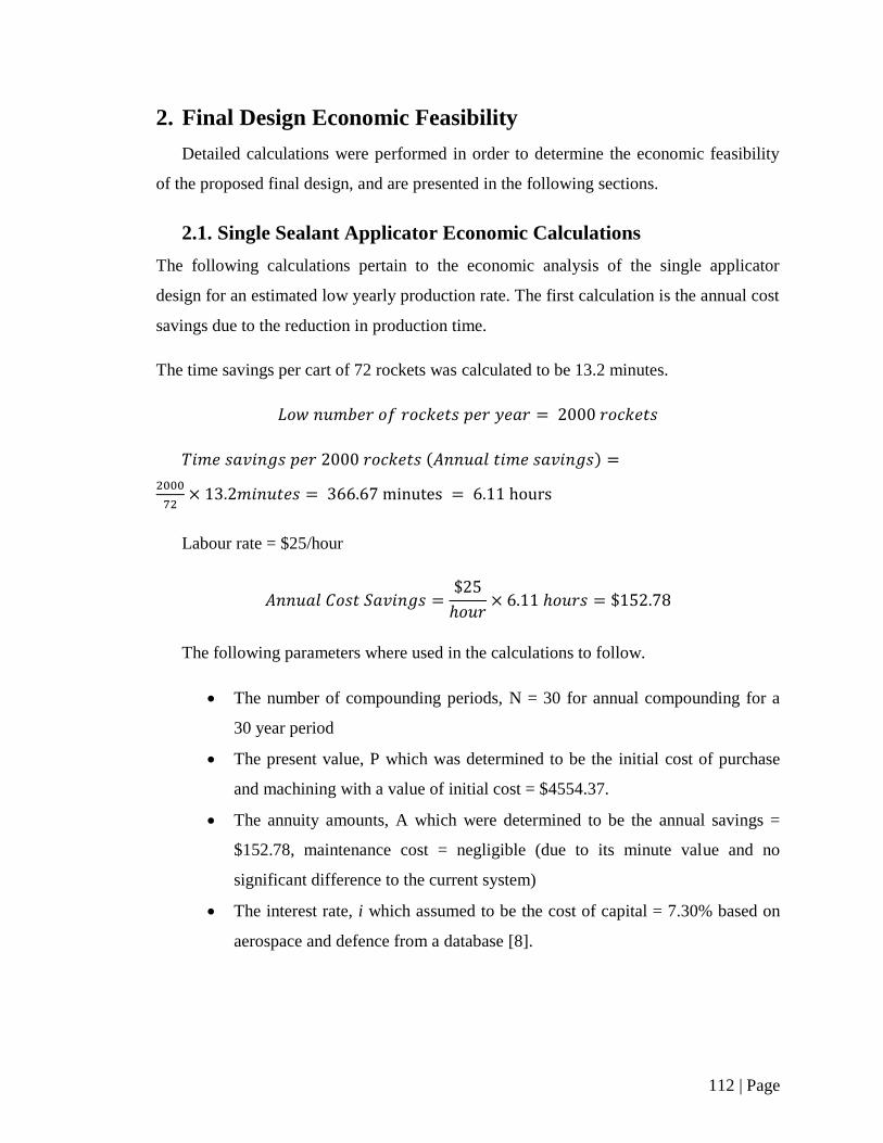
112 | Page
2. Final Design Economic Feasibility
Detailed calculations were performed in order to determine the economic feasibility
of the proposed final design, and are presented in the following sections.
2.1. Single Sealant Applicator Economic Calculations
The following calculations pertain to the economic analysis of the single applicator
design for an estimated low yearly production rate. The first calculation is the annual cost
savings due to the reduction in production time.
The time savings per cart of 72 rockets was calculated to be 13.2 minutes.
( )
Labour rate = $25/hour
The following parameters where used in the calculations to follow.
The number of compounding periods, N = 30 for annual compounding for a
30 year period
The present value, P which was determined to be the initial cost of purchase
and machining with a value of initial cost = $4554.37.
The annuity amounts, A which were determined to be the annual savings =
$152.78, maintenance cost = negligible (due to its minute value and no
significant difference to the current system)
The interest rate, i which assumed to be the cost of capital = 7.30% based on
aerospace and defence from a database [8].
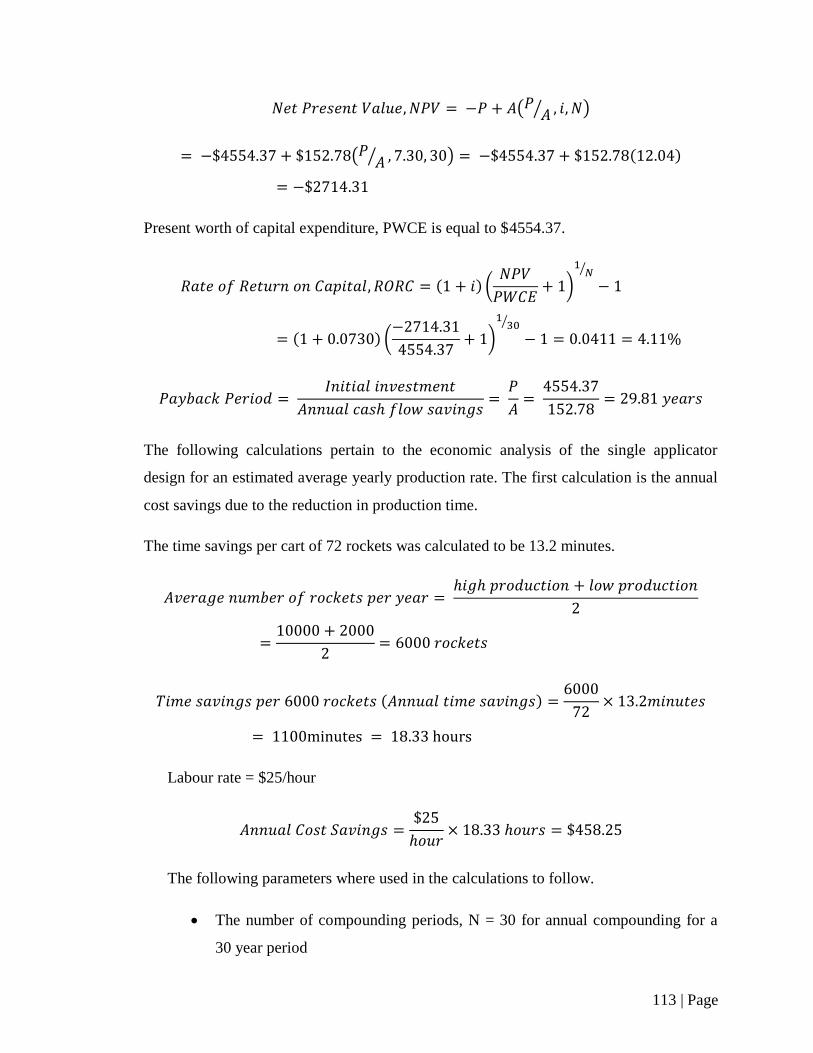
113 | Page
( ⁄ )
( ⁄ ) ( )
Present worth of capital expenditure, PWCE is equal to $4554.37.
( ) (
)
⁄
( ) (
)
⁄
The following calculations pertain to the economic analysis of the single applicator
design for an estimated average yearly production rate. The first calculation is the annual
cost savings due to the reduction in production time.
The time savings per cart of 72 rockets was calculated to be 13.2 minutes.
( )
Labour rate = $25/hour
The following parameters where used in the calculations to follow.
The number of compounding periods, N = 30 for annual compounding for a
30 year period
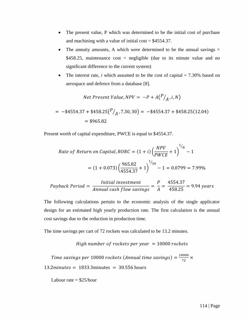
114 | Page
The present value, P which was determined to be the initial cost of purchase
and machining with a value of initial cost = $4554.37.
The annuity amounts, A which were determined to be the annual savings =
$458.25, maintenance cost = negligible (due to its minute value and no
significant difference to the current system)
The interest rate, i which assumed to be the cost of capital = 7.30% based on
aerospace and defence from a database [8].
( ⁄ )
( ⁄ ) ( )
Present worth of capital expenditure, PWCE is equal to $4554.37.
( ) (
)
⁄
( ) (
)
⁄
The following calculations pertain to the economic analysis of the single applicator
design for an estimated high yearly production rate. The first calculation is the annual
cost savings due to the reduction in production time.
The time savings per cart of 72 rockets was calculated to be 13.2 minutes.
( )
Labour rate = $25/hour
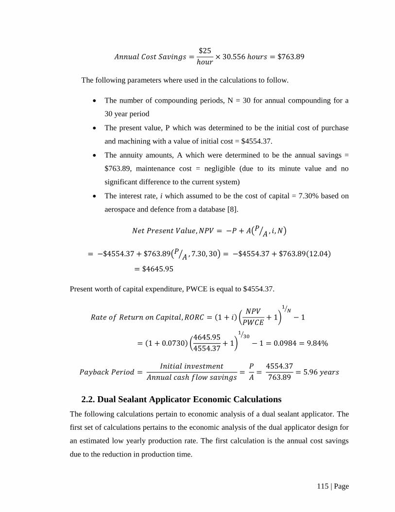
115 | Page
The following parameters where used in the calculations to follow.
The number of compounding periods, N = 30 for annual compounding for a
30 year period
The present value, P which was determined to be the initial cost of purchase
and machining with a value of initial cost = $4554.37.
The annuity amounts, A which were determined to be the annual savings =
$763.89, maintenance cost = negligible (due to its minute value and no
significant difference to the current system)
The interest rate, i which assumed to be the cost of capital = 7.30% based on
aerospace and defence from a database [8].
( ⁄ )
( ⁄ ) ( )
Present worth of capital expenditure, PWCE is equal to $4554.37.
( ) (
)
⁄
( ) (
)
⁄
2.2. Dual Sealant Applicator Economic Calculations
The following calculations pertain to economic analysis of a dual sealant applicator. The
first set of calculations pertains to the economic analysis of the dual applicator design for
an estimated low yearly production rate. The first calculation is the annual cost savings
due to the reduction in production time.

116 | Page
The time savings per cart of 72 rockets was calculated to be 18.6 minutes.
( )
Labour rate = $25/hour
The following parameters where used in the calculations to follow.
The number of compounding periods, N = 30 for annual compounding for a
30 year period
The present value, P which was determined to be the initial cost of purchase
and machining with a value of initial cost = $8160.74.
The annuity amounts, A which were determined to be the annual savings =
$215.28, maintenance cost = negligible (due to its minute value and no
significant difference to the current system)
The interest rate, i which assumed to be the cost of capital = 7.30% based on
aerospace and defence from a database [8].
( ⁄ )
( ⁄ ) ( )
Present worth of capital expenditure, PWCE is equal to $8160.74.
( ) (
)
⁄
( ) (
)
⁄
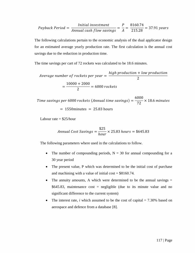
117 | Page
The following calculations pertain to the economic analysis of the dual applicator design
for an estimated average yearly production rate. The first calculation is the annual cost
savings due to the reduction in production time.
The time savings per cart of 72 rockets was calculated to be 18.6 minutes.
( )
Labour rate = $25/hour
The following parameters where used in the calculations to follow.
The number of compounding periods, N = 30 for annual compounding for a
30 year period
The present value, P which was determined to be the initial cost of purchase
and machining with a value of initial cost = $8160.74.
The annuity amounts, A which were determined to be the annual savings =
$645.83, maintenance cost = negligible (due to its minute value and no
significant difference to the current system)
The interest rate, i which assumed to be the cost of capital = 7.30% based on
aerospace and defence from a database [8].

118 | Page
( ⁄ )
( ⁄ ) ( )
Present worth of capital expenditure, PWCE is equal to $8160.74.
( ) (
)
⁄
( ) (
)
⁄
The following calculations pertain to the economic analysis of the dual applicator design
for an estimated high yearly production rate. The first calculation is the annual cost
savings due to the reduction in production time.
The time savings per cart of 72 rockets was calculated to be 18.6 minutes.
( )
Labour rate = $25/hour
The following parameters where used in the calculations to follow.
The number of compounding periods, N = 30 for annual compounding for a
30 year period
The present value, P which was determined to be the initial cost of purchase
and machining with a value of initial cost = $8160.74.

119 | Page
The annuity amounts, A which were determined to be the annual savings =
$1076.93, maintenance cost = negligible (due to its minute value and no
significant difference to the current system)
The interest rate, i which assumed to be the cost of capital = 7.30% based on
aerospace and defence from a database [8].
( ⁄ )
( ⁄ ) ( )
Present worth of capital expenditure, PWCE is equal to $8160.74.
( ) (
)
⁄
( ) (
)
⁄
120 | Page
3. Works Cited
[1] McMASTER-CARR, "McMASTER-CARR," [Online]. Available:
http://www.mcmaster.com/#. [Accessed November 2013].
[2] AutomationDirect.com, [Online]. Available:
http://www.automationdirect.com/adc/Home/Home. [Accessed 2 November 2013].
[3] Equipois Incorporated, "zeroG," [Online]. Available:
http://www.equipoisinc.com/products/zerog4/. [Accessed 2 November 2013].
[4] Flexible Assembly Systems Inc., "QTA 150 110.6 Ft lb (150Nm) Capacity Torque
Reaction Arm," [Online]. Available: http://www.flexibleassembly.com/Products/All-
Flexible-Assembly-Items_2/QTA150. [Accessed 2 November 2013].
[5] Ingersoll Rand, "Lifting/Material Handling," [Online]. Available:
http://www.ingersollrandproducts.com/am-en/products/lifting. [Accessed 2 November
2013].
[6] Global Industrial Canada Inc., "Reelcraft Tool Balancers," [Online]. Available:
http://www.globalindustrial.ca/g/work-benches/components/tool-balancer/reelcraft-
tool-balancers. [Accessed 2 November 2013].
[7] Ergonomic Partners Inc., "Gorbel Free Standing Tool Balancer Jib Crane, Capacity 50
lbs, Span 4 ft, HUB 10 ft, Model TSJ50-FS-50-10-4," [Online]. Available:
http://www.ergonomicpartners.com/product/467/994/Gorbel-Free-Standing-Tool-
Balancer-Jib-Crane-Capacity-50-lbs-Span-4-ft-HUB-10-ft-Model-TSJ50-FS-50-10-
4.aspx. [Accessed 2 November 2013].
[8] dBase, [Online]. Available: http://www.dbase.com/costs-of-capital-by-industry-
sector/. [Accessed 23 November 2013].

121 | Page
Appendix C

122 | Page
Table of Contents – Appendix C
List of Tables ............................................................................................................ 123
Nomenclature ........................................................................................................... 124
1. Gear Stress Calculations .................................................................................. 125
2. Works Cited ..................................................................................................... 131

123 | Page
List of Tables
TABLE I: CHOSEN GEAR CHARACTERISTICS ...................................................... 125
TABLE II: CALCULATED TORQUE AND FORCES ................................................ 126

124 | Page
Nomenclature
Hardness ratio Number of gear teeth
Elastic coefficient Number of load cycles
_ Relating to the drive gear Outside diameter
_ Relating to the driven gear Diametral pitch
Pitch diameter Normal diametral pitch
Rocket internal diameter Pitting stress
Face width Modified pitting stress
Applied force Bending stress
Factor of safety Modified bending stress
Pitting stress geometry factor Torque
Bending stress geometry factor Radial force
Rim thickness modifying factor Tangential force
Load distribution modifying
factor
Axial force
Overload modifying factor Bending stress cycle factor
Reliability modifying factor Pitting stress cycle factor
Size modifying factor Helix angle
Dynamic modifying factor Normal pressure angle
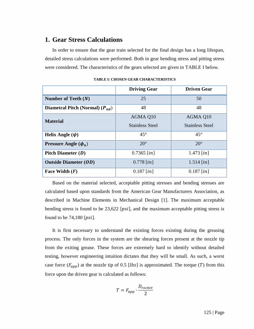
125 | Page
1. Gear Stress Calculations
In order to ensure that the gear train selected for the final design has a long lifespan,
detailed stress calculations were performed. Both in gear bending stress and pitting stress
were considered. The characteristics of the gears selected are given in TABLE I below.
TABLE I: CHOSEN GEAR CHARACTERISTICS
Driving Gear Driven Gear
Number of Teeth ( ) 25 50
Diametral Pitch (Normal) ( ) 48 48
Material AGMA Q10
Stainless Steel
AGMA Q10
Stainless Steel
Helix Angle ( ) 45° 45°
Pressure Angle ( ) 20° 20°
Pitch Diameter ( ) 0.7365 [ ] 1.473 [ ]
Outside Diameter ( ) 0.778 [ ] 1.514 [ ]
Face Width ( ) 0.187 [ ] 0.187 [ ]
Based on the material selected, acceptable pitting stresses and bending stresses are
calculated based upon standards from the American Gear Manufacturers Association, as
described in Machine Elements in Mechanical Design [1]. The maximum acceptable
bending stress is found to be 23,622 [ ], and the maximum acceptable pitting stress is
found to be 74,180 [ ].
It is first necessary to understand the existing forces existing during the greasing
process. The only forces in the system are the shearing forces present at the nozzle tip
from the exiting grease. These forces are extremely hard to identify without detailed
testing, however engineering intuition dictates that they will be small. As such, a worst
case force ( ) at the nozzle tip of 0.5 [ ] is approximated. The torque ( ) from this
force upon the driven gear is calculated as follows:
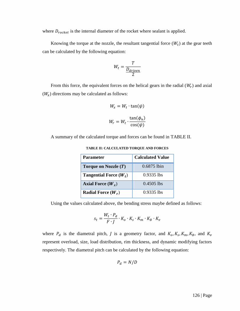
126 | Page
where is the internal diameter of the rocket where sealant is applied.
Knowing the torque at the nozzle, the resultant tangential force ( ) at the gear teeth
can be calculated by the following equation:
From this force, the equivalent forces on the helical gears in the radial ( ) and axial
( ) directions may be calculated as follows:
( )
( )
( )
A summary of the calculated torque and forces can be found in TABLE II.
TABLE II: CALCULATED TORQUE AND FORCES
Parameter Calculated Value
Torque on Nozzle ( ) 0.6875 lbin
Tangential Force ( ) 0.9335 lbs
Axial Force ( ) 0.4505 lbs
Radial Force ( ) 0.9335 lbs
Using the values calculated above, the bending stress maybe defined as follows:
where is the diametral pitch, is a geometry factor, and and
represent overload, size, load distribution, rim thickness, and dynamic modifying factors
respectively. The diametral pitch can be calculated by the following equation:

127 | Page
The geometry factor is found separately for each gear selected from reference
graphs provided in Machine Elements in Mechanical Design [1]. These factors are found
to be 0.3 for the driving gear, and 0.307 for the driven gear respectively.
The modifying factors are all taken from Machine Elements in Mechanical Design,
based on many different factors [1]. The overload factor, , is defined as 1.40,
equivalent to a light shock power source, and light shock driven machine. As the
diametral pitch is greater than 5, the size factor, is equal to 1. The load distribution
factor for the gears is calculated by the following formula, based upon a worst case
scenario open gearing configuration.
where
and
The calculations yield a load distribution factor of 1.2505. The rim thickness factor is
calculated as 1.0, as the ratio of the gear tooth heigh over the rim thickness is
substantially greater than 1.2. Finally the dynamic factor is calculated by the following
equation:
( √
)
where
and
( )
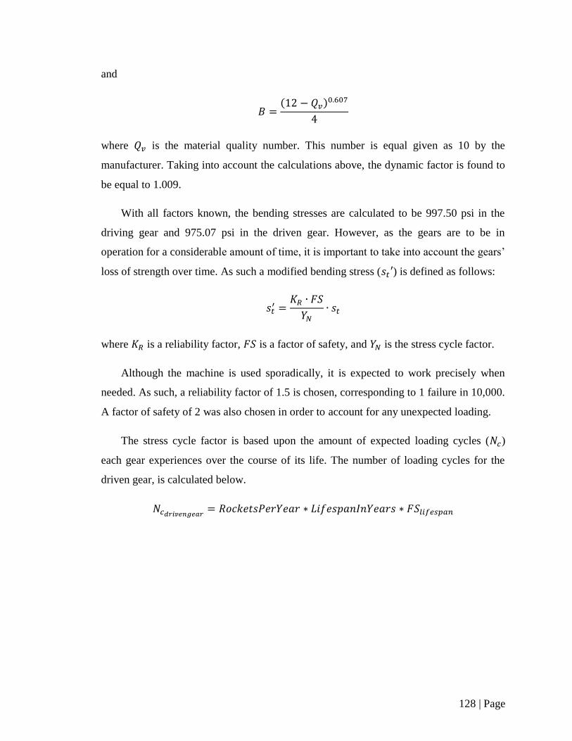
128 | Page
and
( )
where is the material quality number. This number is equal given as 10 by the
manufacturer. Taking into account the calculations above, the dynamic factor is found to
be equal to 1.009.
With all factors known, the bending stresses are calculated to be 997.50 psi in the
driving gear and 975.07 psi in the driven gear. However, as the gears are to be in
operation for a considerable amount of time, it is important to take into account the gears’
loss of strength over time. As such a modified bending stress ( ) is defined as follows:
where is a reliability factor, is a factor of safety, and is the stress cycle factor.
Although the machine is used sporadically, it is expected to work precisely when
needed. As such, a reliability factor of 1.5 is chosen, corresponding to 1 failure in 10,000.
A factor of safety of 2 was also chosen in order to account for any unexpected loading.
The stress cycle factor is based upon the amount of expected loading cycles ( )
each gear experiences over the course of its life. The number of loading cycles for the
driven gear, is calculated below.
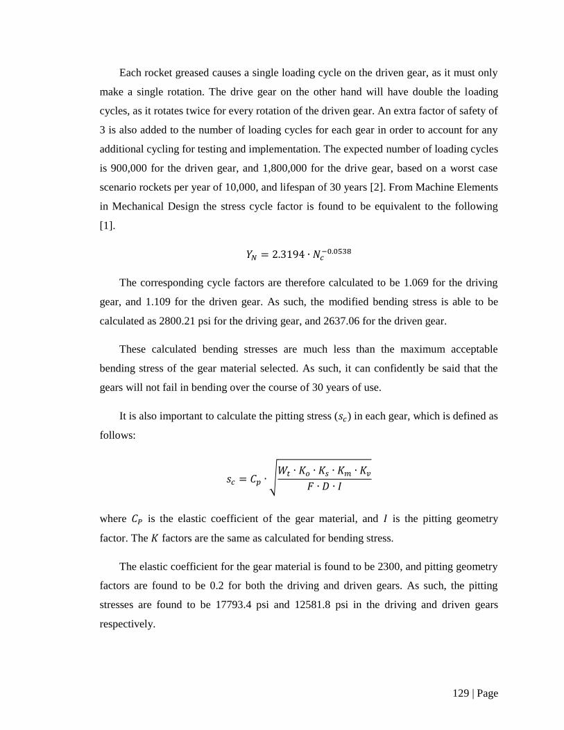
129 | Page
Each rocket greased causes a single loading cycle on the driven gear, as it must only
make a single rotation. The drive gear on the other hand will have double the loading
cycles, as it rotates twice for every rotation of the driven gear. An extra factor of safety of
3 is also added to the number of loading cycles for each gear in order to account for any
additional cycling for testing and implementation. The expected number of loading cycles
is 900,000 for the driven gear, and 1,800,000 for the drive gear, based on a worst case
scenario rockets per year of 10,000, and lifespan of 30 years [2]. From Machine Elements
in Mechanical Design the stress cycle factor is found to be equivalent to the following
[1].
The corresponding cycle factors are therefore calculated to be 1.069 for the driving
gear, and 1.109 for the driven gear. As such, the modified bending stress is able to be
calculated as 2800.21 psi for the driving gear, and 2637.06 for the driven gear.
These calculated bending stresses are much less than the maximum acceptable
bending stress of the gear material selected. As such, it can confidently be said that the
gears will not fail in bending over the course of 30 years of use.
It is also important to calculate the pitting stress ( ) in each gear, which is defined as
follows:
√
where is the elastic coefficient of the gear material, and is the pitting geometry
factor. The factors are the same as calculated for bending stress.
The elastic coefficient for the gear material is found to be 2300, and pitting geometry
factors are found to be 0.2 for both the driving and driven gears. As such, the pitting
stresses are found to be 17793.4 psi and 12581.8 psi in the driving and driven gears
respectively.
130 | Page
As with bending stress, it is important to take into account the detrimental effects of
a lifetime of rotation with regards to the stresses in the gears. A modified pitting stress
( ) was calculated as follows:
where is the pitting resistance cycle factor, and is the hardness ratio factor. and
remain unchanged from the bending stress calculations.
As the driving and driven gear are made of the same material, the hardness ratio
factor is known to be 1.0. From Machine Elements in Mechanical Design the pitting
resistance cycle factor is calculated as the following [1].
The pitting resistance cycle factor is therefore calculated to be 1.101 for the driving
gear, and 1.144 for the driven gear. With all parameters known, the modified pitting
stresses are calculated to be 48,493.4 psi for the driving gear, and 32,984.5 psi for the
driven gear.
The pitting stresses calculated are therefore seen to be less than the maximum
acceptable bending stress of the gear material selected. As such, it can confidently be said
that the gears will not fail due to pitting over the course of 30 years of use.
131 | Page
2. Works Cited
[1] R. L. Mott, Machine Elements in Mechanical Design, United States of America:
Prentice-Hall Inc., 2001.
[2] K. Braid, Interviewee, (Private Communication). [Interview]. 19 September 2013.

132 | Page
Appendix D
133 | Page
Table of Contents – Appendix D
List of Figures........................................................................................................... 134
1. Assembly Drawings ......................................................................................... 135
134 | Page
List of Figures
Figure 1: Application System ......................................................................................... 136
Figure 2: Applicator BOM ............................................................................................. 137
135 | Page
1. Assembly Drawings
The drawings on the following pages showcase the developed assembly in detail.
Figure 1 highlights the full assembly, with subcomponents; the jib crane, spring balancer,
and applicator noted. Figure 2 shows the applicator in higher detail, with a detailed list of
required parts. Section views highlight the applicator dispenser, nozzle, swivel,
powertrain, and body. The drawings were developed for reference purposes only, and
should not be used for construction.
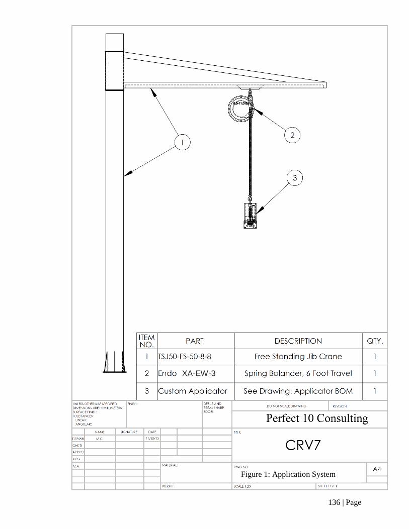
136 | Page
Figure 1: Application System
XA-EW-3
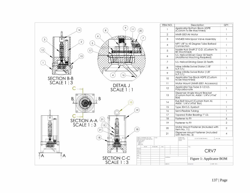
137 | Page
Figure 1: Applicator BOM


