
The MathWorksThe MathWorks®
Crossover to Crossover to ModelModel--Based DesignBased Design
The Ohio State UniversityKerem Koprubasi, Ph.D. Candidate
Mechanical Engineering
The 2008 Challenge X Competition

2
Benefits of MathWorks ToolsBenefits of MathWorks Tools
• Model-based design tools allowed Ohio State to:– Accurately define vehicle technical specifications, – Design and test control strategies in simulation,– Predict vehicle dynamic behavior,– Generate embedded code automatically.
Simulink®: Rapid construction of complex dynamic system models. Graphical environment.
Stateflow®: Effective implementation of state machines. Visual support makes code debugging simple.
Real-Time Workshop®: One-step automatic code generation directly from model. Relieves requirement for advanced programming skills.
MATLAB® Toolboxes: Assist in control design, system optimization, statistical data analysis, and signal processing.

3
Summary of Year 4 Improvements Summary of Year 4 Improvements
• Modeling and Data Analysis– CX-Sim: Quasi-static vehicle simulator for fuel economy
and performance evaluation
– CX-Dyn: Dynamic simulator for drivability assessment and control
– CX-Trac: Detailed tire dynamics for traction control.
– CX-Start: Specialized engine-start simulator.
– CX-DAQ: Data analysis and post-processing tool.
Verified & Validated
Merged
Verified & Validated

4
Summary of Year 4 Improvements Summary of Year 4 Improvements
• Control Strategy Improvements
– Exhaust Aftertreatment Control:• Local regeneration control to achieve substantial NOx emissions
reduction with a low fuel economy penalty.
– Engine Start Control:• Model-based (LQR) strategy to reduce speed overshoot with
minimal calibration.
– Mode-Transition Control:• Torque blending between mode transitions to improve drivability.
– Active Driveline Control:• Electric motor torque control during pedal tip-in/tip-out.
– Adaptive Energy Management Strategy:• From look-up table implementation to calibratable code using an
embedded MATLAB function.

5
MathWorksMathWorks®® Tools in Development ProcessTools in Development Process
Simulation Results- Predicted VTS- Control Strategy
Parameters
System DesignConcept
Model Based Design
YEAR 1
LessonsLearned
LessonsLearned

6
MathWorksMathWorks®® Tools in Development ProcessTools in Development Process
Simulation Results- Predicted VTS- Control Strategy
Parameters
System DesignConcept
Model Based Design Vehicle Integration
LessonsLearned
LessonsLearned
YEAR 2

7
MathWorksMathWorks®® Tools in Development ProcessTools in Development Process
System Design
Vehicle Integration
LessonsLearned
LessonsLearned
Simulation Results- Updated VTS- Tuned Control
Strategy Parameters
Model Based Refinement
YEAR 3

8
MathWorksMathWorks®® Tools in Development ProcessTools in Development Process
System Design
Code Optimization and Verification
LessonsLearned
Model Based Refinement
YEAR 4
In-Vehicle Results- Use of data for model calibration and validation.- Control verification and optimization.

9
Ohio State Vehicle ArchitectureOhio State Vehicle Architecture
• 1.9L (110 kW) Diesel Engine (ICE)
• 6-Speed Automatic Transmission
• 32 kW Traction Electric Machine (EA)
• 10 kW Belted Starter Alternator (BSA)
• 300V Nominal Ni-MH Battery Pack
• Dual LNT Exhaust After-treatment System
• DC/DC Converter for 12V accessories

10
HybridHybrid--Electric Vehicle ModesElectric Vehicle Modes

Modeling and Experimental Modeling and Experimental ValidationValidation

12
CXCX--SIM: Energy ModelingSIM: Energy Modeling
CX-SIM• Quasi-Static Vehicle
Simulator
• Fuel Economy and Basic Performance Evaluation
• Control Strategy Development and Tuning
Year 4 Improvements:• Model is validated (no driver feedback) with experimental data.
Control Commands In Vehicle States Out Compare with Data
• Battery, engine and torque converter models are revised as a result of the experimental validation.

13
CXCX--SIM: Experimental ValidationSIM: Experimental Validation

14
CXCX--DYN: Dynamic Drivability ModelDYN: Dynamic Drivability Model
CX-DYN• Low frequency dynamic model
suited for drivability and fuel economy evaluation.
• Gear shift transients, driveline shuffle, actuator delays.
Year 4 Improvements:• Improved automatic transmission
model (including engine start-stop).
• New Pacejka tire model.
• New driveline model with backlash.
• Model calibration.

15
CXCX--DYN: Experimental ValidationDYN: Experimental Validation
• Mild acceleration from 0 to 25 mph
Engine Start
1-2 shift
2-3 shift
16
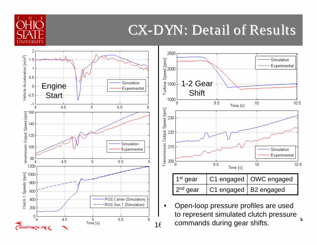
CXCX--DYN: Detail of ResultsDYN: Detail of Results
Engine Start
1-2 Gear Shift
B2 engagedC1 engaged2nd gearOWC engagedC1 engaged1st gear
• Open-loop pressure profiles are used to represent simulated clutch pressure commands during gear shifts.

17
• A similar dynamic HEV model can be built using SimDriveline thus achieving substantial time savings.
• This simulator consists of a combination of custom built components and SimDriveline blocks.
SimDrivelineSimDriveline Equivalent ModelEquivalent Model
ICE & BSA
EM
Clutch Controls

18
CXCX--DYN DYN –– SimDrivelineSimDriveline ComparisonComparison
Engine start
• The SimDriveline model gives similar results as CX-DYN despite the low level of model calibration.
• 1-2 gear shift is captured more accurately with CX-DYN.(same clutch pressure profiles are used in both models)
1-2 gear shift

19
CXCX--DYN DYN –– SimDrivelineSimDriveline ComparisonComparison
All components are custom built.
Some components need to be customized for application.
Easier to troubleshoot.Not trivial to troubleshoot errors during model development.
Cons
Time-consuming to run simulations.
Simulations can be run in a matter of seconds.
Requires considerable effort and know-how to build.
Complex vehicle models can be quickly built.
Pros
CX-Dyn simulatorSimDriveline simulator

20
CXCX--START: Engine Start ModelSTART: Engine Start Model
CX-START• Stand-alone simulator• Detailed models of
– diesel engine – starter alternator – belt dynamics
for engine start-stop control.
Engine Start Model Validation
Engine Stop Model Validation

Data Analysis and Data Analysis and Model VerificationModel Verification

22
Vehicle Data Analysis: CXVehicle Data Analysis: CX--DAQDAQ
CX-DAQ
• Data analysis and post-processing
• Simple handling of CAN data
• Supporting tool for model validation

23
Simulation Data Analysis: CXSimulation Data Analysis: CX--GraphicsGraphics
CX-Graphics
• Developed in Year 1
• For use with developed vehicle simulators.
• Analyze simulation results.

24
Model Checking and VerificationModel Checking and Verification
• Model verification toolset simplifies…
Hardware fault diagnosis:
Simulation error debugging: Control strategy verification:
Send fault bit if inverter temperature is out of range.
Stop simulation if engine speed < 0. Stop simulation if torque command is out of limits.

Control Design, ImplementationControl Design, Implementationand and
OptimizationOptimization

26
Supervisory ControlsSupervisory Controls
• Supervisory control strategies implemented using Stateflow.
– High-level exhaust after-treatment controls.
– Vehicle mode management
StateflowSimulink

27
Adaptive Energy Optimization StrategyAdaptive Energy Optimization Strategy
• Equivalent fuel Consumption Minimization Strategy (ECMS): – An adaptive algorithm to minimize “weighted equivalent fuel use”:
}min{arg ,∑⋅+=i
iEQfuelISAEMICE msm} , T, T{T &&
⎩⎨⎧⋅
⋅=
Chargingif),,(gDischarginif,),(1
, uxux
QTm
LHV
iiiEQ
φ
φ
ηηω
&
– Equivalence Factor, s: Updated online based on driving cycle characteristics and battery state-of-charge (SOC).
Equivalent fuel for electric machines
IPss ζζ ⋅⋅= nominal
SOC Control: Gains are modified when SOC deviates from nominal range (50-80%).
Opt
imum
Equ
ival
ence
Fa
ctor

28
Adaptive ECMS TuningAdaptive ECMS Tuning
• MATLAB Statistics Toolbox is used to recognize the past driving pattern and adaptively tune the control strategy.
• Driving cycle clusters are formed based on 18 statistical metrics.
Commands: kmeans, silhoutte, boxplot, princomp, pareto

29
Implementation Implementation -- Code OptimizationCode Optimization
• ECMS code is implemented using an embedded MATLAB function.• Look-up table data types are optimized for low memory use.• Computational capacity of the vehicle control unit (code “turnaround
time”) is monitored to ensure proper operation.
• Fuel minimization strategy modified for efficient real-time implementation.
TBSA
TEM
x
Search Space
Current O.P.
Benefits:• Fast code execution.• Reduces “torque chattering”.• Advantageous for initialization during controller transfer.
Look-up table MATLAB code suitable for implementationYear 3 Year 4

Other Control ImprovementsOther Control Improvements
• Battery Charge Estimation
• Driveline Controls

31
Battery StateBattery State--ofof--Charge EstimationCharge Estimation
Frequency separation principle:
3700 3800 3900 4000 4100 4200 4300 4400 45006
6.5
7
7.5
8
8.5
9
9.5
10
10.5Measurement
Simulation • Experimental battery model (used for open-circuit voltage estimation) is improved in year 4.
• Estimator’s weighting algorithm is improved.
Battery Voltage
Simulink

32
Battery StateBattery State--ofof--Charge EstimationCharge Estimation
• Improved initialization.
• Accurate response to short-term charge variations.
• Proven stability.
0 1000 2000 3000 400040
50
60
70
80
90
100
Time [s]
SoC
[%]
SOC EstimationCoulomb IntegrationVoltage Estimation
• Cumulative bias in the current measurement is compensated by the SOC estimator.
** Year 3 algorithm over-responsiveto voltage variations at low charge/ discharge rates.
** **

33
Engine Start: Engine Speed ControlEngine Start: Engine Speed Control
• Engine start strategy revised in year 4.
• PI-type engine start controller replaced with a model-based (LQR) controller:
Less calibration effort.
• LQR controller eliminates engine speed overshoot.
• Less BSA torque is used to start the engine: Better fuel economy.
Year 3 Result
Year 4 Improvement
Control Design Toolbox : lqr

34
• A torque blending strategy is implemented to avoid driveline disturbances after engine start.
• A model-based hybrid control technique is used.
Engine Start: Torque BlendingEngine Start: Torque Blending
Year 4 Improvement
Mode Transition Mode Transition
Vehicle Acceleration and Driveline Speeds
• This method exploits the benefits of the fast dynamic response of the electric machines.
Year 3 Result

35
Electric Mode: Driveline ControlElectric Mode: Driveline Control
• Gear backlash and the absence of a damping element causes torquedisturbances in the rear driveline during pedal tip-in tip-out.
EM & DrivelineDynamics
Compensator
EM TorqueRequest
EM Speed
Activate when tip-in/tip-out is detected
TorqueCompensation
-
+
Change ingear contact
direction
Overshoot eliminated
Improved
Open-loop
Closed-loopClosed-loop
Open-loop
Active driveline damping technique

Control ArchitectureControl Architecture• Hardware
• Software

37
Control Hardware ArchitectureControl Hardware Architecture
Battery Control Unit - Phytec development board (Freescale MPC555).
Vehicle Control Unit - dSPACE MicroAutoBox1401.
Exhaust Control Unit - MotoTron ECU-80.

38
Control Software ArchitectureControl Software Architecture
• Operations are divided into 4 sampling times (1-10-100-1000 ms).• Sampling times are selected according to the task priorities and the
computational burdens of code segments.• Operations are processed in multiple timer task mode.
• MathWorks tools simplify the control development and code generation processes.
• Automatic code generation process works seamlessly regardless of the choice of the embedded target.
Embedded Target Toolbox
Real-Time Workshop
Embedded Target
Simulink /Stateflow
Target Compiler
Simulink Control Model
MathWorksTools
Automatic Code
Generation
Vehicle Controller Software Specifications

39
Lessons Learned in Year 4Lessons Learned in Year 4
• MathWorks tools greatly simplified:
• Design of simulation models and data analysis,
• Design, implementation and verification of control strategies.
• Pros and cons of using custom designed simulators versus using modeling packages (such as SimDriveline) are well-understood.
• Code optimization is crucial to achieve high control performance. More emphasis should be placed on code optimization if the control application is production intended.
• Current experiences will be carefully documented and deliveredto the next competition team to minimize their initial learning period.

Questions ?Questions ?
Thank you for your attention.Thank you for your attention.


