
Cotter joint
FIG 01: ASSEMBLED COTTERED JOINT

• Cotter is flat wedge shape piece of rectangular c/s
and width is tapered (either one side or both side)
from one end to another for an easy adjustment.
• The taper varies from 1 in 48 to 1 in 24 and it may
be increased to 1 in 8 if locking is provided.
• A cotter joint is temporary fastening and using to
connect rapidly two co-axial rods or bars which are
subjected to tensile or compressive forces.
• Ex- Connection between piston rod and cross head
of a steam engine, valve rod and its steam, steam
engine connecting rod strap ends, etc.
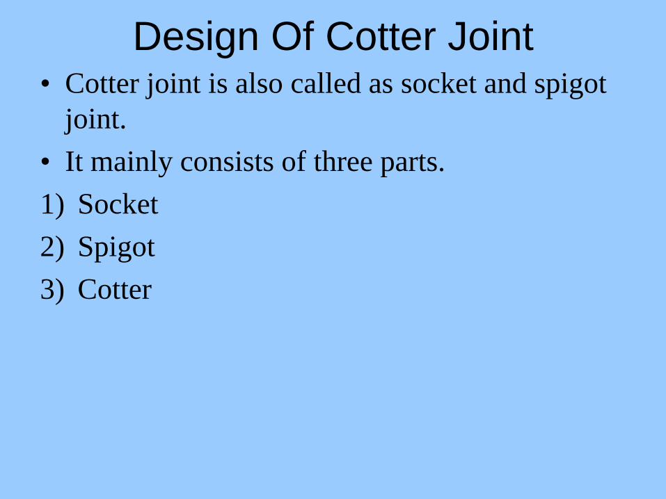
Design Of Cotter Joint • Cotter joint is also called as socket and spigot
joint.
• It mainly consists of three parts.
1) Socket
2) Spigot
3) Cotter
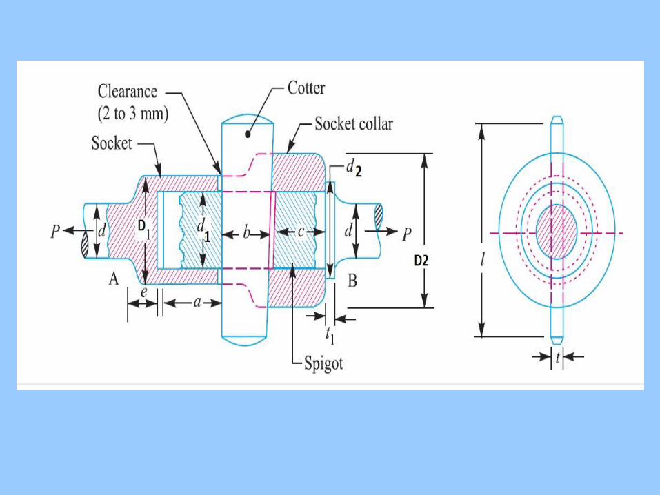
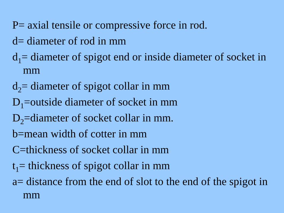
P= axial tensile or compressive force in rod.
d= diameter of rod in mm
d1= diameter of spigot end or inside diameter of socket in
mm
d2= diameter of spigot collar in mm
D1=outside diameter of socket in mm
D2=diameter of socket collar in mm.
b=mean width of cotter in mm
C=thickness of socket collar in mm
t1= thickness of spigot collar in mm
a= distance from the end of slot to the end of the spigot in
mm
terandspigotsocketforstressshearepermissibl
terandspigotsocketforstresscrushingepermissibl
terandspigotsocketforstresstensileepermissibl
crc
t
cot,
cot,
cot,
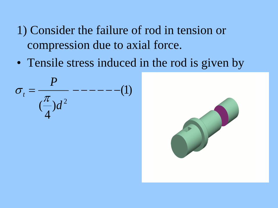
1) Consider the failure of rod in tension or
compression due to axial force.
• Tensile stress induced in the rod is given by
)1(
)4
( 2
d
Pt
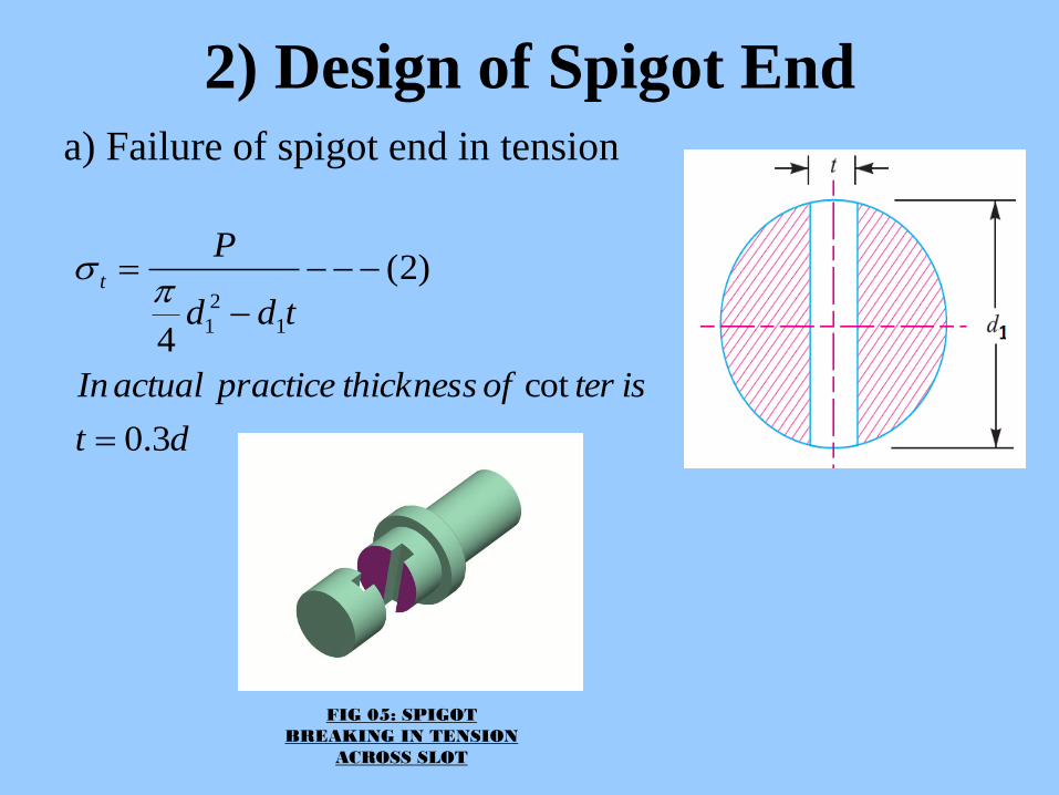
2) Design of Spigot End
dt
isterofthicknesspracticeactualIn
tdd
Pt
3.0
cot
)2(
41
2
1
FIG 05: SPIGOT
BREAKING IN TENSION
ACROSS SLOT
a) Failure of spigot end in tension
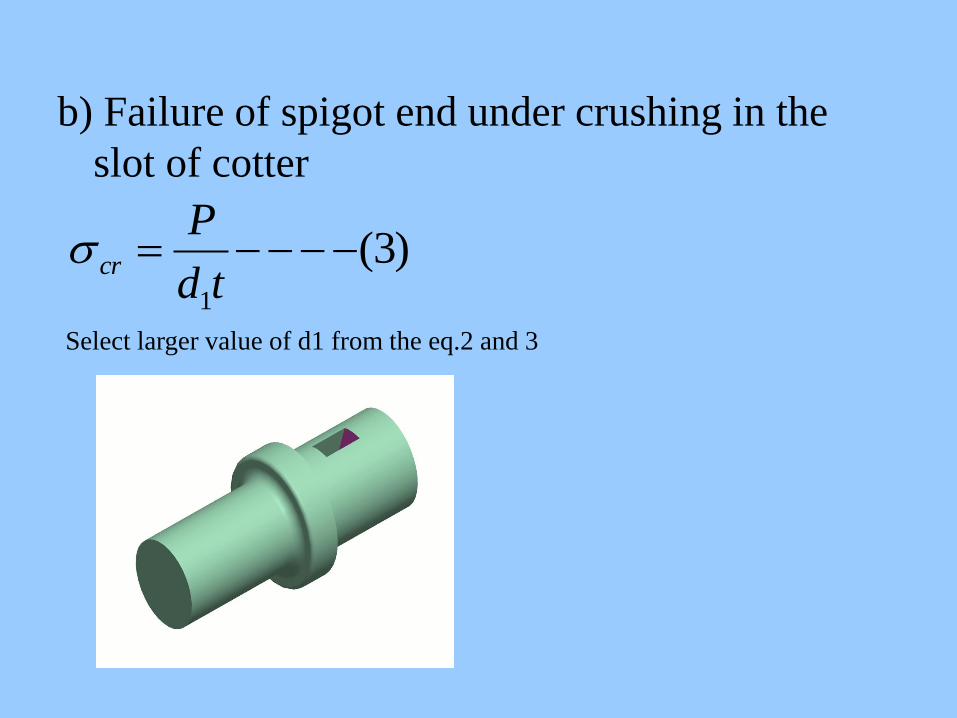
b) Failure of spigot end under crushing in the
slot of cotter
)3(
1
td
Pcr
Select larger value of d1 from the eq.2 and 3
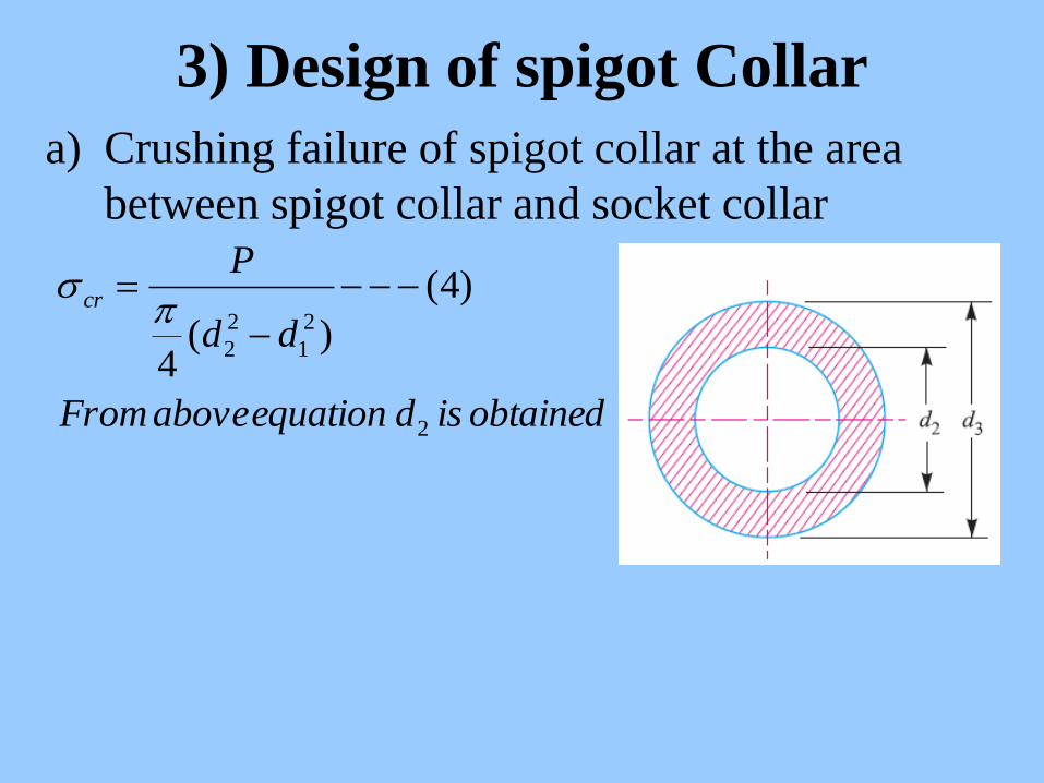
3) Design of spigot Collar
a) Crushing failure of spigot collar at the area
between spigot collar and socket collar
obtainedisdequationaboveFrom
dd
Pcr
2
2
1
2
2
)4(
)(4
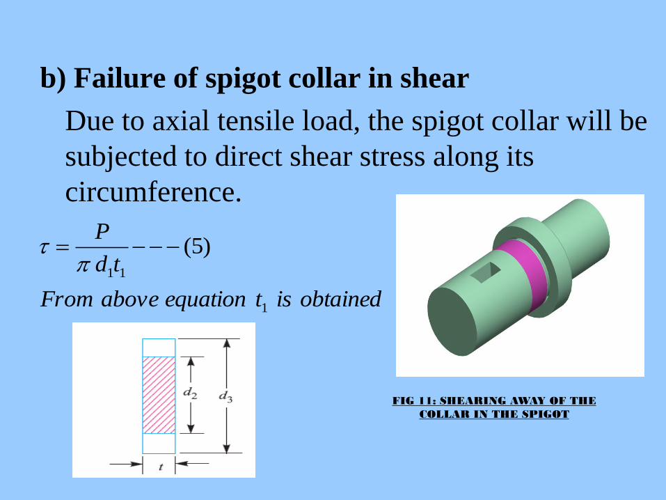
b) Failure of spigot collar in shear
Due to axial tensile load, the spigot collar will be
subjected to direct shear stress along its
circumference.
obtainedistequationaboveFrom
td
P
1
11
)5(
FIG 11: SHEARING AWAY OF THE
COLLAR IN THE SPIGOT
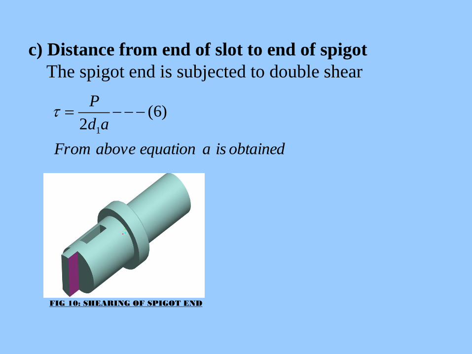
obtainedisaequationaboveFrom
ad
P)6(
2 1
c) Distance from end of slot to end of spigot
The spigot end is subjected to double shear
FIG 10: SHEARING OF SPIGOT END

4) Design of Socket
obtainedisDeqaboveFrom
tdDdD
P
n
t
1
11
2
1
2
1
)7(
])[()](4
[

5) Design of socket collar Crushing failure of socket collar at the area
between socket collar and cotter.
obtainedisDeqaboveFrom
tdD
P
n
cr
2
12
)8()(
FIG 08: CRUSHING OF COTTER PIN AGAINST
SOCKET

6) Thickness of socket collar
The socket collar is subjected to double shear.
obtainedisCeqaboveFrom
CdD
P
n
)9()(2 12

7) Find distance ‘e’ of the socket end
• The socket end is subjected to shear failure.
obtaiediseeqaboveFrom
ed
P
n ''
)10(
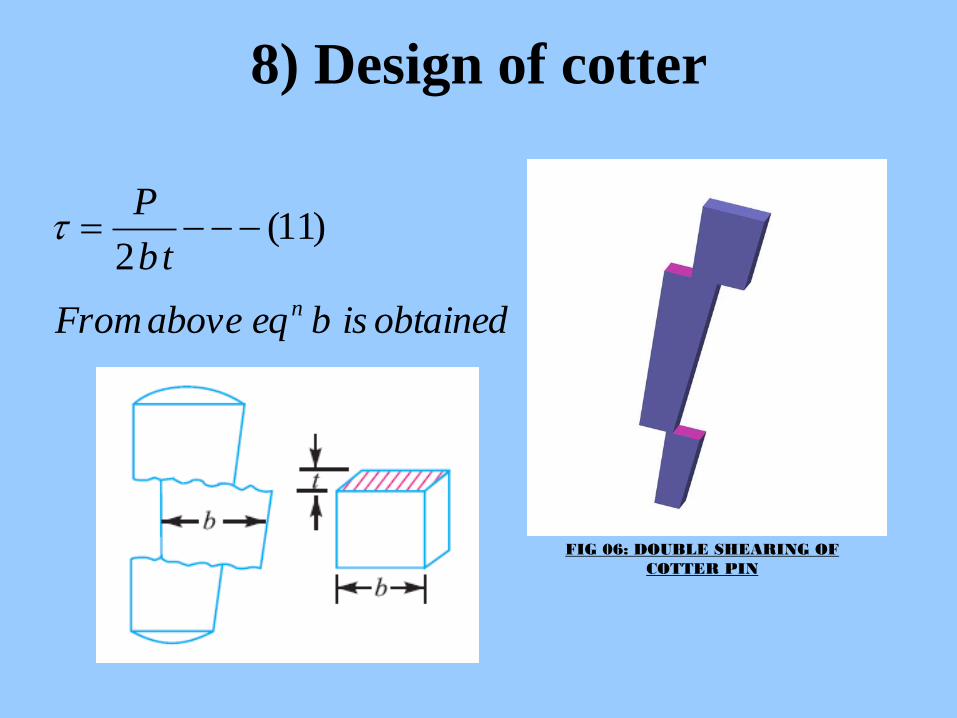
8) Design of cotter
obtainedisbeqaboveFrom
tb
P
n
)11(2
FIG 06: DOUBLE SHEARING OF
COTTER PIN
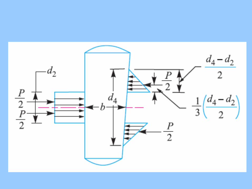

b) Failure of cotter in bending
)12(4
)2(
)46
(2
6
6
)6
(
]46
[2
]426
[2
)42
(]2
)2
(3
1[
2..
2
12
2
112
2
max
2
max
max
112max
1112
1112
bt
dDP
bt
ddDP
bt
M
bt
M
Z
M
ddDPM
dddDP
dPddDPMB
b
b
b

• From equation 12 ‘b’ is obtained.
• The larger value of ‘b’ is taken from equation 11
and 12.
• Length of cotter is taken as L=4d
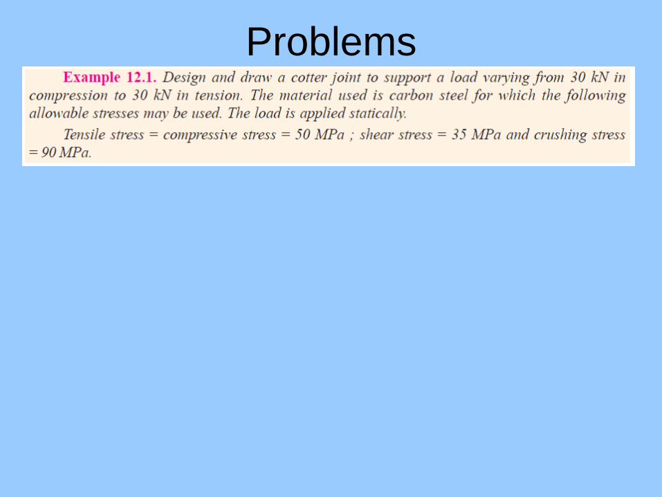
Problems


