Proceedings World Geothermal Congress 2015
Melbourne, Australia, 19-25 April 2015
1
Control of Metal Sulfide Deposits in Geothermal Binary Plants
Logan Muller1, Jasbir S Gill
2, David Rodman
3, Kevin Brown
4 and Ray Robinson
5
Nalco An Ecolab Company, Naperville Il USA; 4. Geokem, Christchurch, NZ; 5. Top Energy, Kaikohe, NZ
Keywords: Stibnite inhibition, Metal Sulfide cleaning and inhibition, EGS, Colloid, Silica
ABSTRACT
Geothermal power generation is growing due to the need for clean renewable energy. Traditional dry steam generation plants have
been in operation in countries where Geothermal dry steam is prevalent for several decades e.g., New Zealand, Iceland, Philippines.
However as the cost and environmental impact of fossil fuel power generation is realized, more effort is being placed into more
complex geothermal use such as low enthalpy power plants and EGS or Hot Rock technology plants. These latter technologies
bring a raft of chemical complexity to power generation in particular Silica and metal Sulfides. Whilst Silica and Arsenic Sulfides
are well researched, comparatively little is known about Antimony Sulfide. The absence of chemical inhibitors for the sulfide
compounds has resulted in significant fouling of some geothermal plants causing losses of power output, thereby reducing the
economic viability of these plants. Recent developmental work at the Ngawha Generation site in New Zealand has shown a
significant step forward in the control of Antimony Sulfide deposition in binary plant heat exchangers. This plant was taking
generation units off line for cleans every 12 weeks due to the loss of power production resulting from Antimony Sulfide scale. This
paper outlines how these metal Sulfides have been prevented from depositing, providing improved power output, reduced need for
cleaning and, subsequent, minimization of handling these toxics deposits. There may be important implications for EGS
technologies as the toxic metal Sulfides have presented a barrier to consistent power production in at least one test site.
1. INTRODUCTION
Fossil Fuel Resource depletion coupled with climate change has increased global attention to conserving resources and their
effective and efficient use. There has been a great deal of advances to improve the efficiency of the traditional steam generation
plants (HRSG systems are common place). After the Japan disaster, the public has become very sceptical about the nuclear energy.
To meet ever increasing need of world energy there has been a growth in renewable energy developments. One significant
investment is being in geothermal power generation. Most other renewable resources such as wind and solar cannot be base loaded,
thus has to depend on alternate sources of energy to continually supply electricity to the customers. Once a proven source of
geothermal energy, it can be base loaded for decades to generate power.
The University of Utah Energy and Geoscience Institute estimates the accessible global Geothermal magmatic energy reserves to
be over 400 times that of all known oil reserves (Hulen et.al., 2001) Geothermal growth and current developments reflect this with
significant geothermal installations in Africa, Latin America, Europe, USA, Asia and the South Pacific. However, Geothermal too
has moved from the more straight forward capture and use of dry steam for generation to more complex systems where magmatic
steam and low enthalpy aquifers are now being tapped. These newer technologies and growth from low enthalpy resources has
brought new challenges in terms of scaling and corrosion of the geothermal assets. Low enthalpy extraction technologies are also
being adopted as the return on capital investment in geothermal extraction shifts to be more favorable. In two phase steam systems
a steam turbine is sometimes followed by a binary plant that uses the brine or low pressure steam and low boiling point organic
solvent such as isopentane to generate additional electricity. The binary technologies allow additional energy extraction and power
generation.
In Enhanced Geothermal Systems (EGS) the mechanical and geological challenges of finding and targeting suitable crystalline or
granite strata with suitable permeability, or able to artificially create suitable permeability, is one significant barrier. The other
challenges are the chemical composition of the steam/water mix that it generates and the non-condensable gases. Either a natural
water source is present, or one needs to be artificially created by pumping surface water into the subsurface fracture/aquifer system.
The similarities in the challenges with binary and EGS technologies is the control of more unusual compounds such as metal
sulfides and silicates and corrosion.
This paper is a follow up to GRC paper (Muller et.al. 2014) describing in depth the results from the field evaluation of technology
to mitigate deposit on the heat exchangers caused by metal sulfide particularly, antimony sulphide.
2. THE ISSUES
Deposition of silica, antimony and arsenic compounds is significant enough to warrant serious investment in complex test plants
prior to investing in the construction of binary generation plants. Addison and Brown (Addison, Brown, 2012) document the in-
depth process of determining optimal design parameters to prevent the deposition of these compounds in the binary plant at
Ngatamariki New Zealand. The challenge is that the highly insoluble metal sulfides are extremely sensitive to temperature and pH
(Figure 1).
Many plants are designed around the calculated saturation indices to prevent or minimize the deposition of these compounds. This
creates tight operating conditions and in the ever increasing pressure on power generation companies to produce more power these
conditions are easily exceeded. Whilst temperature control is an effective way of preventing deposition it also comes at a cost; a
four degree increase in the brine discharge temperature of a binary plant from 90 to 94oC can cost 10% of production capacity.
However as Addison, Brown, and Ngatamariki in 2011 noted; to date there had been no successful chemical treatment for antimony
sulfides (stibnite) and that “Present options for remediation include caustic soda washing, steam cleaning and mechanical removal”.

Muller et al.
2
The plant operation and, at an earlier stage, design is left with the option of progressively losing efficiency as scaling occurs and the
ongoing costs of chemical (usually caustic) cleans , hydro blasting, downtime, and disposing of the hazardous wastes, or, designing
the plant to operate at temperatures above which there is no fouling of the exchangers. pH adjustment is becoming common in
plants where acid is used to prevent silica deposition in reinjection lines and wells but this is neither appropriate when antimony
sulfide exceeds its equilibrium solubility nor has the longer term effects of significant acid reinjection into the aquifer been
thoroughly researched. Corrosion can be a significant cost in assets under acidic operating conditions.
Figure 1: Example of impact of temperature and pH on Stibnite solubility (Sb at 1.3ppm and H2S 82ppm).
Gill (2011) published lab results indicating that a fresh approach to the control of deposition was possible through the use of
specialty polymers. Gill, et al. (2013) published results that demonstrated that these polymers significantly reduced deposition in
side stream trials and a live plant trial. The Ngawha generation plant where these tests were confirmed is unique in that it has many
of the metal sulfide, calcite and silica issues that are being faced in the aforementioned technologies. Careful management and
expert input from GEOKEM have enabled the plant to find operating parameters to stay in production and in fact expand
operations.
The antimony sulfide deposits that form in the binary plant heat exchangers and reinjection pipe work are both crystalline or
“stibnite” and amorphous antimony sulfide (“metastibnite”). Further analysis of the metastibnite forms has led to a focus on the
formation mechanisms of the deposits and in particular to colloidal structures of antimony sulfide. Whilst the deposition is
predominantly in the binary preheaters, a steady decline in the capacity of the reinjection wells has also been experienced.
The operations team regularly forced higher pressures down the reinjection wells that temporarily improved reinjection rates.
However the ‘bounce back’ periods kept on shortening, indicating that this approach was becoming less effective. The other
potential courses of action were to incrementally reduce plant capacity, caustic clean the reinjection wells, or invest in an extensive
capital project to connect a new reinjection well.
The risks associated with each one of these options are significant. Reduction in plant output to operate within the limits of the
reinjectability means reinjection pumps are constantly running at near trip pressures and amperages and the ongoing cost
accumulates as power production reduces. The option of caustic cleaning the well means the well must be taken offline, costing
generation capacity and runs the risk of precipitating calcite downhole potentially worsening the problem. Connecting another
reinjection well is a significant capital expense and neither offers a quick nor sustainable solution. The modelling for the cost
benefit analysis is not straight forward as the rate of loss of reinjection is nonlinear.
In all of the solutions above, none actually stop the root cause of the issue: deposition was affecting the long term performance of
the reinjection wells, as the wells continued to lose injection capability.
The solution has been to pull the metal sulfide and silica knowledge of GEOKEM, the experience TOP Energy has gained in the
way it manages the physical processes of the plant to mitigate deposition problems together with the research, international
Geothermal experience and polymer development capability of Nalco together to brainstorm synergistic approaches.
This collaborative approach has shown to produce some important advancements for the industry.

Muller et al.
3
3. CHEMICAL APPROACH
Calcite inhibition is relatively commonplace and the mechanisms of threshold inhibition and dispersion are often employed.
Historically these have been low molecular weight polyacrylates. However these have been shown to be ineffective against the
deposition of the metal sulfides and silica. A standard threshold inhibitor of a proprietary polyphosphonate was lab tested on
antimony sulfide but it was not effective against preventing its deposition. This performance comparison is based on the authors’
definition of threshold inhibition, where particles <0.2 microns are considered soluble antimony. The importance of particle size is
discussed in the “Discussion” section and plays an important role in the final results. Based on these results, it brings credence to
the hypothesis that for highly insoluble salts such as antimony sulfide, certain polymers with high anionic charge density are very
effective in reducing the particle size and imparting negative charge to the precipitating particles and therefore are more effective
than traditional threshold inhibitors such as phosphonates. It is thus quite challenging to inhibit the formation of minerals with
extremely low equilibrium solubility and for such minerals the best strategy to mitigate fouling is to accept the precipitation but
modify the characteristics of the precipitated particles. By targeting the early formation of the particles with highly anionic co-
polymer, the particle then can take on an apparent negative polarity. This keeps the particle size small (colloidal see later), increases
dispersion and enable electro-osmosis which pulls water molecules along with the precipitate (Hunter, 1996).
Compounding the issues of antimony in geothermal applications is the ability to test and quantify colloidal forms of antimony in
brine. Acidic digestion is a method referred to by Norman (Norman, 1998) but the efficacy of colloidal measurement is only
referred to in its uses in tracing in human diagnostics. However it is the formation of colloidal antimony sulfide that appears to be
leading to the successes in deposit inhibition and removal referred to later in this paper. Modification of the precipitant once formed
was found to be more effective at preventing deposition than attempting threshold inhibition of precipitant formation, this has been
reported previously (Gill et al., 2013).
4. TRIAL RIG RESULTS
A small test rig was constructed with two test coils cooling the incoming brine to 80oC off the main brine supply line to the Ormat
binary unit. One was dosed with the polymer and the other left as a control. After a month the coils were destructively tested by
Geokem. The results of this trial are shown in Following Figure 2 and discussed by Gill et.al.2013.
Error! Reference source not found.Figure 2: Antimony sulfide deposition inhibition trial using a pilot scale heat exchanger.
Based on these results a plant trial was initiated. The results of which are discussed below. Antimony sulfide deposition is almost
quantitative with temperature but as has been subsequently experienced the mechanical dynamics, pH and flow characteristics can
play an important part in determining deposition location and severity. This further complicates plant design around theoretical
parameters such as temperature dependent saturation indices.
5. PLANT IMPACTS
There were several changes noted in the plant. These are discussed under the following headings.
1. Temporary increase in soluble calcium levels
2. Increase in capacity of reinjection wells
3. Significant reduction in fouling rates of the binary units.
4. Change in the physical characteristics of deposits.
5. Pressure drops across binary exchangers at high dosage.
5.1 Temporary Increase in Soluble Calcium Levels
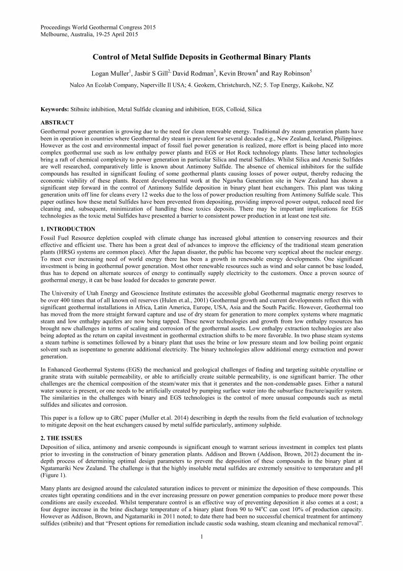
The plant had been using a traditional polyacrylate for several years for the control of calcite. This had been keeping the wells at
full flow and pressure since 2008. However once the copolymer was used downhole, the soluble Ca levels in the brine increased
indicating removal of Ca from the downhole system (Figure 3). The soluble Ca levels decreased to initial values after a month,
suggesting that whatever was able to be dissolved had been removed. The results suggest that the chelating properties of the
copolymer were responsible for dissolving the calcium deposits. Additionally there was a decrease in the pump pressures needed to
dose the inhibitor and a reduction in overall cost of 50% for the calcite inhibition.
Muller et al.
4
Figure 3: Calcium measurements in production well brine comparing traditional treatment and modified treatment
(circled). Elevated Ca level indicates calcite removal from well casing.
5.2 Increase in Capacity of Injection Wells
The relationship between flow and pressure was used and recorded as Kon. For turbulent flows between a Reynolds number of
3000 and 10000 the flow pressure relationship is relatively constant at a given roughness and diameter of the reinjection lines and
reinjection well casings at Ngawha.
Figure 4 shows the steady decline of capacity of the reinjection wells prior to trialing chemical treatment. The loss of reinjection
flow was at the point of reducing plant capacity. According to the independent consultancy from GEOKEM the loss of reinjection
capacity was due ‘probably to the build-up of silica or antimony sulfides in the casing or immediate reinjection zone of the aquifer’.
After dosing the copolymer at 4 ppm for two months it was observed that the decline in injection capacity (a declining Kon value)
stopped and, in fact, the well increased in capacity. It was decided to conduct a short period high dose (from 4 ppm to 30ppm) for
five days in (Figure 5).
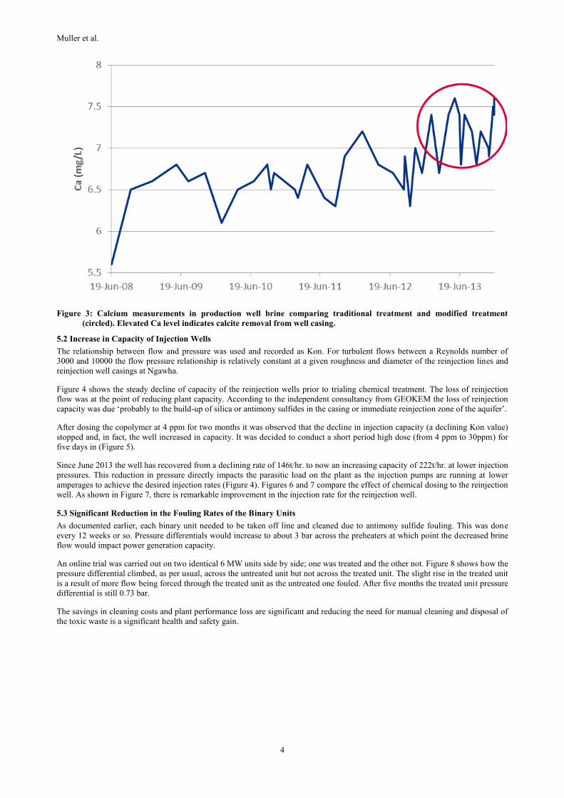
Since June 2013 the well has recovered from a declining rate of 146t/hr. to now an increasing capacity of 222t/hr. at lower injection
pressures. This reduction in pressure directly impacts the parasitic load on the plant as the injection pumps are running at lower
amperages to achieve the desired injection rates (Figure 4). Figures 6 and 7 compare the effect of chemical dosing to the reinjection
well. As shown in Figure 7, there is remarkable improvement in the injection rate for the reinjection well.
5.3 Significant Reduction in the Fouling Rates of the Binary Units
As documented earlier, each binary unit needed to be taken off line and cleaned due to antimony sulfide fouling. This was done
every 12 weeks or so. Pressure differentials would increase to about 3 bar across the preheaters at which point the decreased brine
flow would impact power generation capacity.
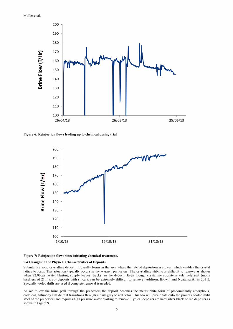
An online trial was carried out on two identical 6 MW units side by side; one was treated and the other not. Figure 8 shows how the
pressure differential climbed, as per usual, across the untreated unit but not across the treated unit. The slight rise in the treated unit
is a result of more flow being forced through the treated unit as the untreated one fouled. After five months the treated unit pressure
differential is still 0.73 bar.
The savings in cleaning costs and plant performance loss are significant and reducing the need for manual cleaning and disposal of
the toxic waste is a significant health and safety gain.

Muller et al.
5
Figure 4: Typical reinjection well performance decline prior to chemical dosing
Figure 5: Reinjection well performance improvement during initial chemical injection.
y = -0.0023x + 9.7045
y = -0.0019x + 14.809
0
2
4
6
8
10
12
14
16
18
20
Ko
n
Time Days April 1 to June 30, 2013
NG11 Kon
NG18 Kon
y = 0.0059x + 9.4356
9.1
9.2
9.3
9.4
9.5
9.6
9.7
9.8
9.9
10
10.1
1 5 9 1317212529333741454953576165697377818589
Ko
n
Number of Days from April1 to June 30,2013
NG11 Kon
Linear (NG11 Kon)
Muller et al.
6
Figure 6: Reinjection flows leading up to chemical dosing trial
Figure 7: Reinjection flows since initiating chemical treatment.
5.4 Changes in the Physical Characteristics of Deposits.
Stibnite is a solid crystalline deposit. It usually forms in the area where the rate of deposition is slower, which enables the crystal
lattice to form. This situation typically occurs in the warmer preheaters. The crystalline stibnite is difficult to remove as shown
when 22,000psi water blasting simply leaves ‘tracks’ in the deposit. Even though crystalline stibnite is relatively soft (mohs
hardness of 2) if it co- deposits with silica it can be extremely difficult to remove (Addison, Brown, and Ngatamariki in 2011).
Specially tooled drills are used if complete removal is needed.
As we follow the brine path through the preheaters the deposit becomes the metastibnite form of predominantly amorphous,
colloidal, antimony sulfide that transitions through a dark grey to red color. This too will precipitate onto the process cooled mild
steel of the preheaters and requires high pressure water blasting to remove. Typical deposits are hard silver black or red deposits as
shown in Figure 9.
100
110
120
130
140
150
160
170
180
190
200
26/04/13 26/05/13 25/06/13
Bri
ne
Flo
w (
T/H
r)
100
110
120
130
140
150
160
170
180
190
200
1/10/13 16/10/13 31/10/13
Bri
ne
Flo
w (
T/H
r)
Muller et al.
7
Figure 8: Differential pressures across two OEC units, one treated and the other not treated.
Figure 9: Metastibnite deposition on a pump impeller.
After the online test it was noted the deposits had become softer and more “pasty”. These deposits were easier to remove and have
led to the prospect of performing online cleaning using the copolymer. At the time of writing, promising initial results have been
obtained and are the focus of further collaborative work.
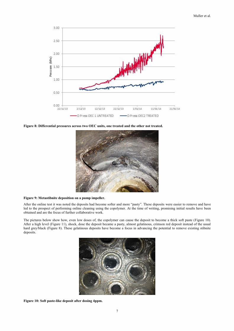
The pictures below show how, even low doses of, the copolymer can cause the deposit to become a thick soft paste (Figure 10).
After a high level (Figure 11), shock, dose the deposit became a pasty, almost gelatinous, crimson red deposit instead of the usual
hard grey/black (Figure 8). These gelatinous deposits have become a focus in advancing the potential to remove existing stibnite
deposits.
Figure 10: Soft paste-like deposit after dosing 4ppm.
Muller et al.
8
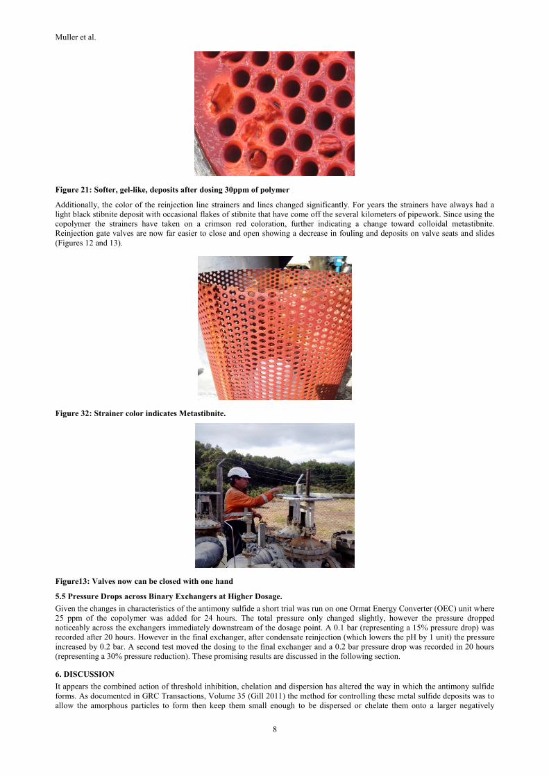
Figure 21: Softer, gel-like, deposits after dosing 30ppm of polymer
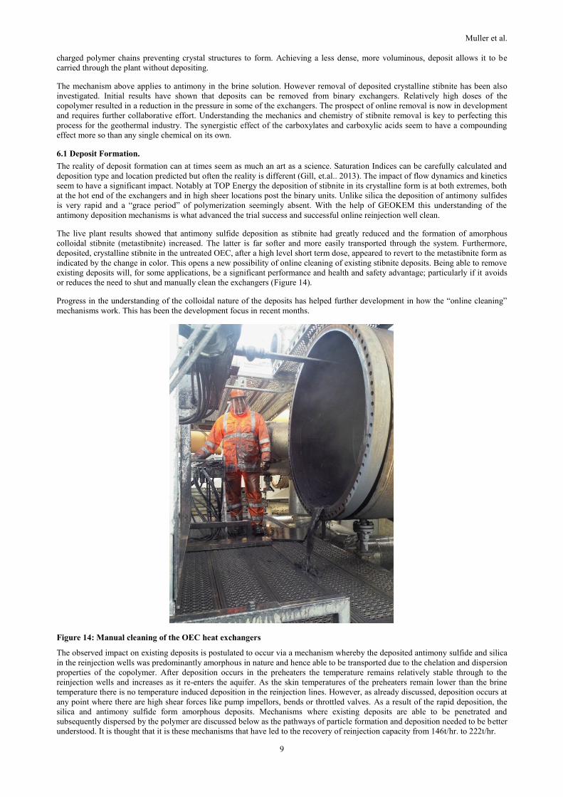
Additionally, the color of the reinjection line strainers and lines changed significantly. For years the strainers have always had a
light black stibnite deposit with occasional flakes of stibnite that have come off the several kilometers of pipework. Since using the
copolymer the strainers have taken on a crimson red coloration, further indicating a change toward colloidal metastibnite.
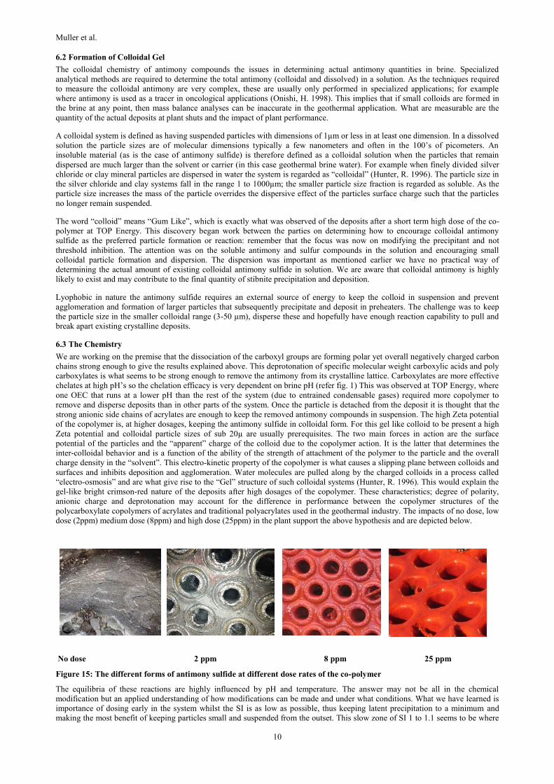
Reinjection gate valves are now far easier to close and open showing a decrease in fouling and deposits on valve seats and slides
(Figures 12 and 13).
Figure 32: Strainer color indicates Metastibnite.
Figure13: Valves now can be closed with one hand
5.5 Pressure Drops across Binary Exchangers at Higher Dosage.
Given the changes in characteristics of the antimony sulfide a short trial was run on one Ormat Energy Converter (OEC) unit where
25 ppm of the copolymer was added for 24 hours. The total pressure only changed slightly, however the pressure dropped
noticeably across the exchangers immediately downstream of the dosage point. A 0.1 bar (representing a 15% pressure drop) was
recorded after 20 hours. However in the final exchanger, after condensate reinjection (which lowers the pH by 1 unit) the pressure
increased by 0.2 bar. A second test moved the dosing to the final exchanger and a 0.2 bar pressure drop was recorded in 20 hours
(representing a 30% pressure reduction). These promising results are discussed in the following section.
6. DISCUSSION
It appears the combined action of threshold inhibition, chelation and dispersion has altered the way in which the antimony sulfide
forms. As documented in GRC Transactions, Volume 35 (Gill 2011) the method for controlling these metal sulfide deposits was to
allow the amorphous particles to form then keep them small enough to be dispersed or chelate them onto a larger negatively
Muller et al.
9
charged polymer chains preventing crystal structures to form. Achieving a less dense, more voluminous, deposit allows it to be
carried through the plant without depositing.
The mechanism above applies to antimony in the brine solution. However removal of deposited crystalline stibnite has been also
investigated. Initial results have shown that deposits can be removed from binary exchangers. Relatively high doses of the
copolymer resulted in a reduction in the pressure in some of the exchangers. The prospect of online removal is now in development
and requires further collaborative effort. Understanding the mechanics and chemistry of stibnite removal is key to perfecting this
process for the geothermal industry. The synergistic effect of the carboxylates and carboxylic acids seem to have a compounding
effect more so than any single chemical on its own.
6.1 Deposit Formation.
The reality of deposit formation can at times seem as much an art as a science. Saturation Indices can be carefully calculated and
deposition type and location predicted but often the reality is different (Gill, et.al.. 2013). The impact of flow dynamics and kinetics
seem to have a significant impact. Notably at TOP Energy the deposition of stibnite in its crystalline form is at both extremes, both
at the hot end of the exchangers and in high sheer locations post the binary units. Unlike silica the deposition of antimony sulfides
is very rapid and a “grace period” of polymerization seemingly absent. With the help of GEOKEM this understanding of the
antimony deposition mechanisms is what advanced the trial success and successful online reinjection well clean.
The live plant results showed that antimony sulfide deposition as stibnite had greatly reduced and the formation of amorphous
colloidal stibnite (metastibnite) increased. The latter is far softer and more easily transported through the system. Furthermore,
deposited, crystalline stibnite in the untreated OEC, after a high level short term dose, appeared to revert to the metastibnite form as
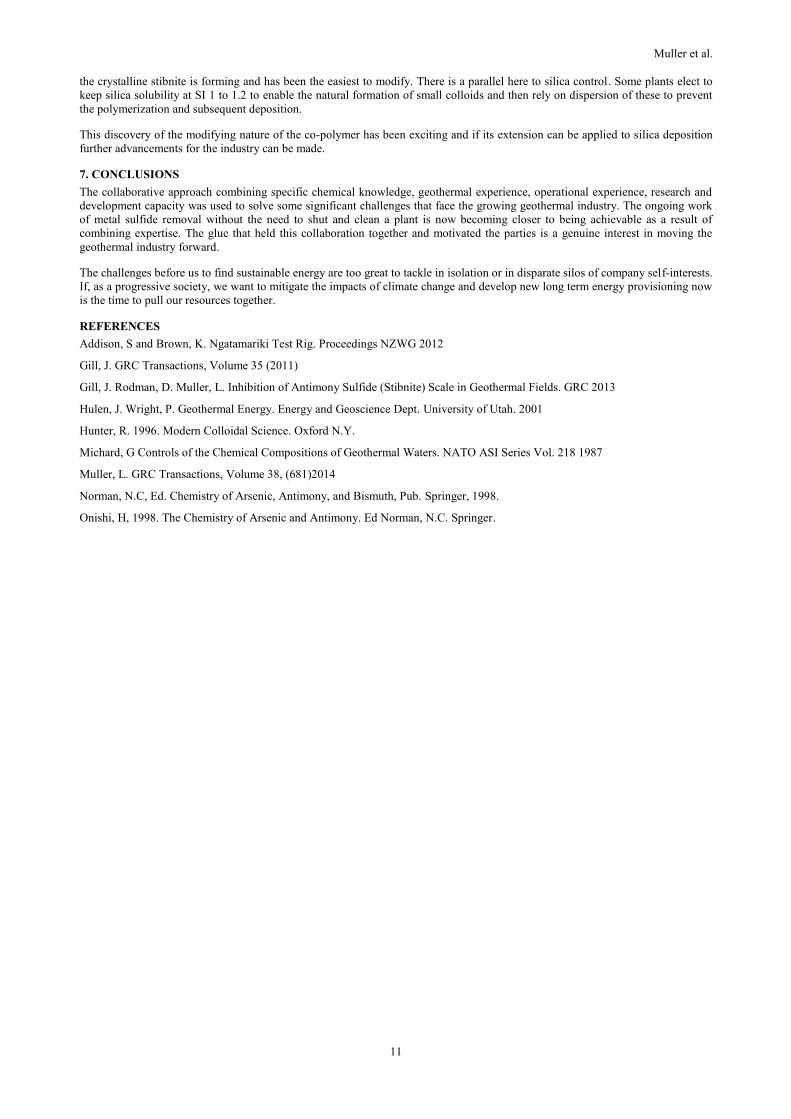
indicated by the change in color. This opens a new possibility of online cleaning of existing stibnite deposits. Being able to remove
existing deposits will, for some applications, be a significant performance and health and safety advantage; particularly if it avoids
or reduces the need to shut and manually clean the exchangers (Figure 14).
Progress in the understanding of the colloidal nature of the deposits has helped further development in how the “online cleaning”
mechanisms work. This has been the development focus in recent months.
Figure 14: Manual cleaning of the OEC heat exchangers
The observed impact on existing deposits is postulated to occur via a mechanism whereby the deposited antimony sulfide and silica
in the reinjection wells was predominantly amorphous in nature and hence able to be transported due to the chelation and dispersion
properties of the copolymer. After deposition occurs in the preheaters the temperature remains relatively stable through to the
reinjection wells and increases as it re-enters the aquifer. As the skin temperatures of the preheaters remain lower than the brine
temperature there is no temperature induced deposition in the reinjection lines. However, as already discussed, deposition occurs at
any point where there are high shear forces like pump impellors, bends or throttled valves. As a result of the rapid deposition, the
silica and antimony sulfide form amorphous deposits. Mechanisms where existing deposits are able to be penetrated and
subsequently dispersed by the polymer are discussed below as the pathways of particle formation and deposition needed to be better
understood. It is thought that it is these mechanisms that have led to the recovery of reinjection capacity from 146t/hr. to 222t/hr.
Muller et al.
10
6.2 Formation of Colloidal Gel
The colloidal chemistry of antimony compounds the issues in determining actual antimony quantities in brine. Specialized
analytical methods are required to determine the total antimony (colloidal and dissolved) in a solution. As the techniques required
to measure the colloidal antimony are very complex, these are usually only performed in specialized applications; for example
where antimony is used as a tracer in oncological applications (Onishi, H. 1998). This implies that if small colloids are formed in
the brine at any point, then mass balance analyses can be inaccurate in the geothermal application. What are measurable are the
quantity of the actual deposits at plant shuts and the impact of plant performance.
A colloidal system is defined as having suspended particles with dimensions of 1µm or less in at least one dimension. In a dissolved
solution the particle sizes are of molecular dimensions typically a few nanometers and often in the 100’s of picometers. An
insoluble material (as is the case of antimony sulfide) is therefore defined as a colloidal solution when the particles that remain
dispersed are much larger than the solvent or carrier (in this case geothermal brine water). For example when finely divided silver
chloride or clay mineral particles are dispersed in water the system is regarded as “colloidal” (Hunter, R. 1996). The particle size in
the silver chloride and clay systems fall in the range 1 to 1000µm; the smaller particle size fraction is regarded as soluble. As the
particle size increases the mass of the particle overrides the dispersive effect of the particles surface charge such that the particles
no longer remain suspended.
The word “colloid” means “Gum Like”, which is exactly what was observed of the deposits after a short term high dose of the co-
polymer at TOP Energy. This discovery began work between the parties on determining how to encourage colloidal antimony
sulfide as the preferred particle formation or reaction: remember that the focus was now on modifying the precipitant and not
threshold inhibition. The attention was on the soluble antimony and sulfur compounds in the solution and encouraging small
colloidal particle formation and dispersion. The dispersion was important as mentioned earlier we have no practical way of
determining the actual amount of existing colloidal antimony sulfide in solution. We are aware that colloidal antimony is highly
likely to exist and may contribute to the final quantity of stibnite precipitation and deposition.
Lyophobic in nature the antimony sulfide requires an external source of energy to keep the colloid in suspension and prevent
agglomeration and formation of larger particles that subsequently precipitate and deposit in preheaters. The challenge was to keep
the particle size in the smaller colloidal range (3-50 µm), disperse these and hopefully have enough reaction capability to pull and
break apart existing crystalline deposits.
6.3 The Chemistry
We are working on the premise that the dissociation of the carboxyl groups are forming polar yet overall negatively charged carbon
chains strong enough to give the results explained above. This deprotonation of specific molecular weight carboxylic acids and poly
carboxylates is what seems to be strong enough to remove the antimony from its crystalline lattice. Carboxylates are more effective
chelates at high pH’s so the chelation efficacy is very dependent on brine pH (refer fig. 1) This was observed at TOP Energy, where
one OEC that runs at a lower pH than the rest of the system (due to entrained condensable gases) required more copolymer to
remove and disperse deposits than in other parts of the system. Once the particle is detached from the deposit it is thought that the
strong anionic side chains of acrylates are enough to keep the removed antimony compounds in suspension. The high Zeta potential
of the copolymer is, at higher dosages, keeping the antimony sulfide in colloidal form. For this gel like colloid to be present a high
Zeta potential and colloidal particle sizes of sub 20µ are usually prerequisites. The two main forces in action are the surface
potential of the particles and the “apparent” charge of the colloid due to the copolymer action. It is the latter that determines the
inter-colloidal behavior and is a function of the ability of the strength of attachment of the polymer to the particle and the overall
charge density in the “solvent”. This electro-kinetic property of the copolymer is what causes a slipping plane between colloids and
surfaces and inhibits deposition and agglomeration. Water molecules are pulled along by the charged colloids in a process called
“electro-osmosis” and are what give rise to the “Gel” structure of such colloidal systems (Hunter, R. 1996). This would explain the
gel-like bright crimson-red nature of the deposits after high dosages of the copolymer. These characteristics; degree of polarity,
anionic charge and deprotonation may account for the difference in performance between the copolymer structures of the
polycarboxylate copolymers of acrylates and traditional polyacrylates used in the geothermal industry. The impacts of no dose, low
dose (2ppm) medium dose (8ppm) and high dose (25ppm) in the plant support the above hypothesis and are depicted below.
No dose 2 ppm 8 ppm 25 ppm
Figure 15: The different forms of antimony sulfide at different dose rates of the co-polymer
The equilibria of these reactions are highly influenced by pH and temperature. The answer may not be all in the chemical
modification but an applied understanding of how modifications can be made and under what conditions. What we have learned is
importance of dosing early in the system whilst the SI is as low as possible, thus keeping latent precipitation to a minimum and
making the most benefit of keeping particles small and suspended from the outset. This slow zone of SI 1 to 1.1 seems to be where
Muller et al.
11
the crystalline stibnite is forming and has been the easiest to modify. There is a parallel here to silica control. Some plants elect to
keep silica solubility at SI 1 to 1.2 to enable the natural formation of small colloids and then rely on dispersion of these to prevent
the polymerization and subsequent deposition.
This discovery of the modifying nature of the co-polymer has been exciting and if its extension can be applied to silica deposition
further advancements for the industry can be made.
7. CONCLUSIONS
The collaborative approach combining specific chemical knowledge, geothermal experience, operational experience, research and
development capacity was used to solve some significant challenges that face the growing geothermal industry. The ongoing work
of metal sulfide removal without the need to shut and clean a plant is now becoming closer to being achievable as a result of
combining expertise. The glue that held this collaboration together and motivated the parties is a genuine interest in moving the
geothermal industry forward.
The challenges before us to find sustainable energy are too great to tackle in isolation or in disparate silos of company self-interests.
If, as a progressive society, we want to mitigate the impacts of climate change and develop new long term energy provisioning now
is the time to pull our resources together.
REFERENCES
Addison, S and Brown, K. Ngatamariki Test Rig. Proceedings NZWG 2012
Gill, J. GRC Transactions, Volume 35 (2011)
Gill, J. Rodman, D. Muller, L. Inhibition of Antimony Sulfide (Stibnite) Scale in Geothermal Fields. GRC 2013
Hulen, J. Wright, P. Geothermal Energy. Energy and Geoscience Dept. University of Utah. 2001
Hunter, R. 1996. Modern Colloidal Science. Oxford N.Y.
Michard, G Controls of the Chemical Compositions of Geothermal Waters. NATO ASI Series Vol. 218 1987
Muller, L. GRC Transactions, Volume 38, (681)2014
Norman, N.C, Ed. Chemistry of Arsenic, Antimony, and Bismuth, Pub. Springer, 1998.
Onishi, H, 1998. The Chemistry of Arsenic and Antimony. Ed Norman, N.C. Springer.


