
CONTINUOUS FLOW ROUTING (CFR): AWIRELESS AD HOC NETWORK ROUTING
PROTOCOL FOR SUPPORTINGMULTIMEDIA FLOWS
a thesis
submitted to the department of computer engineering
and the institute of engineering and science
of bilkent university
in partial fulfillment of the requirements
for the degree of
master of science
By
Ahmet KARA
July, 2006

I certify that I have read this thesis and that in my opinion it is fully adequate,
in scope and in quality, as a thesis for the degree of Master of Science.
Assist. Prof. Dr. Ibrahim Korpeoglu(Advisor)
I certify that I have read this thesis and that in my opinion it is fully adequate,
in scope and in quality, as a thesis for the degree of Master of Science.
Assist. Prof. Dr. Ilyas Cicekli
I certify that I have read this thesis and that in my opinion it is fully adequate,
in scope and in quality, as a thesis for the degree of Master of Science.
Assoc. Prof. Dr. Ezhan Karasan
Approved for the Institute of Engineering and Science:
Prof. Dr. Mehmet B. BarayDirector of the Institute
ii
ABSTRACT
CONTINUOUS FLOW ROUTING (CFR): A WIRELESSAD HOC NETWORK ROUTING PROTOCOL FOR
SUPPORTING MULTIMEDIA FLOWS
Ahmet KARA
M.S. in Computer Engineering
Supervisor: Assist. Prof. Dr. Ibrahim Korpeoglu
July, 2006
Multimedia flows require special routing layer support in ad hoc networks
due their unique characteristics and certain requirements on packet delay, jitter,
loss rate and bandwidth. In this thesis we propose a wireless ad hoc routing
protocol (called CFR) with route discovery and maintenance mechanisms, that
is specifically designed for better supporting multimedia flows in wireless ad hoc
networks. Since multimedia flows are long durational, it is important to route
them through stable routes in order to minimize route failures and disturbance
on the flows. We propose to improve the stability by considering the energy
drain rates and estimated remaining lifetimes of nodes while selecting the best
routes. Additionally we provide a maintenance scheme that acts pro-actively
and re-routes the traffic if a node starts getting very low energy. For this we
define two thresholds on remaining lifetime of a node. After the first threshold is
reached, the node re-routes some of its flows so that the traffic load on the node
is reduced. This helps to an even distribution of traffic to nodes of an ad hoc
network. After the second threshold is reached, the node has very few energy
and therefore redirects all its traffic to some other routes so that the flows are
not disturbed by the route failure when the node depletes all of its energy and
can not route anymore. We implemented the protocol as part of an ns2-based
simulator and proved that it works correctly. Additionally, we compared the
protocol against some other similar protocols. The results show that CFR can
indeed help supporting multimedia flows better.
Keywords: Ad-Hoc Networking, Route Maintanence, Multimedia Streaming.
iii

OZET
SUREKLI AKIS YONLENDIRMESI (SAY): TASARSIZ
AGLARDA COKLU ORTAM SUNULARINIDESTEKLEMEK ICIN YONLENDIRME YONTEMI
Ahmet KARA
Bilgisayar Muhendisligi, Yuksek Lisans
Tez Yoneticisi: Yrd. Doc. Dr. Ibrahim Korpeoglu
Temmuz, 2006
Coklu ortam sunuları; sahip oldukları ozel nitelikler ve paketlerdeki ge-
cikme, gecikme miktarındaki dalgalanma ve paket kaybı oranı gibi ozel
ihtiyacları nedeniyle, tasarsız aglarda yonlendirme seviyesinden destege ihtiyac
duymaktadırlar. Bu tez icerisinde, tasarsız aglarda coklu ortam sunularının
basarımını artırmak amacıyla gerceklenmis, yonlendirme kesif ve bakım mekaniz-
malarından olusan, SAY yontemini sunmaktayız. Coklu ortam sunuları uzun
omurlerinden dolayı hatalardan uzak dayanıklı yonlendirmelere ihtiyac duyul-
maktadır. Yonlendirmelerin dayanıklılıgını artırmak icin enerji seviyesindeki
azalma oranı ve bilesenlerin kalan omurlerini hesaba katarak en iyi yonlendirme
secilmektedir. Ayrıca sundugumuz bakım sistemi sayesinde bir bilesenin enerji-
sinin cok azaldıgı durumlarda, daha bir hata ortaya cıkmadan yonlendirmeler
degistirilerek tehlikeli bilesen dısarıda bırakılmaktadır. Bilesenlerin kalan
omurlerine baglı iki esik degeri tanımlanmıstır. Ilk esik degerine erisildiginde
bilesenler uzerlerindeki akısların bir kısmını bakıma alarak uzerlerindeki yuku
azaltmaktadırlar. Bu sayede ag uzerindeki yukun tum bilesenlere mumkun
oldugunca esit dagıtılması da saglanmaktadır. Bilesenin cok az omru kaldıgında
ikinci esik degerine erisilir ve bilesenin uzerindeki tum akıslar bakıma alınarak her-
hangi bir akısın kesintiye ugraması engellenir. Yontemimizi ns2 tabanlı simulator
uzerinde gercekleyerek yontemin dogrulugunu kanıtladık. Ayrıca diger yontemler
ile kıyaslayarak yontemimizin basarısını olctuk. Elde ettigimiz sonuclara gore
SAY, coklu ortam sunularının basarımını artırmaya destek saglamaktadır.
Anahtar sozcukler : Tasarsız Aglar, Yonlendirme Bakımı, Coklu Ortam Sunuları.
iv

To my mother, Birsen KARA...
v

Acknowledgement
I would like to express my gratitude to my supervisor Assist. Prof. Dr.
Ibrahim Korpeoglu for his realistic, encouraging and constructive approach
throughout my masters study and his efforts and patience during supervision
of the thesis.
I would like to express my since appreciation to the jury members, Assist.
Prof. Dr. Ilyas Cicekli, and Assoc. Prof. Dr. Ezhan Karasan for reviewing and
evaluating my thesis.
I thank to the members of Networking and Systems Group at Bilkent Univer-
sity during the years 2003 to 2006 for their comments on my studies and for the
sparks they caused.
I also thank to the Scientific and Technical Research Council of Turkey
(TUBITAK) for its support to the project with grant number 104E028.
I would like to express my appreciation to TUBITAK UEKAE / ILTAREN
for the understanding and support during my academic studies. I also want to
thank to people I work with for the joy they bring to my life making my business
life together with academic life a pleasureful experience.
I thank to my wife, who became the light of life with her patience and morale
support during my studies.
Finally, I would like to express my thanks to my parents, making me who I
am now with their love, trust, freedom understanding and every kind of support
throughout my life.
vi
Contents
1 Introduction 1
2 Background 8
2.1 Wireless Computer Networks . . . . . . . . . . . . . . . . . . . . 8
2.2 Wireless Ad Hoc Networks . . . . . . . . . . . . . . . . . . . . . . 11
2.3 Ad Hoc Routing Protocols . . . . . . . . . . . . . . . . . . . . . . 13
2.3.1 DSR . . . . . . . . . . . . . . . . . . . . . . . . . . . . . . 14
2.3.2 AODV . . . . . . . . . . . . . . . . . . . . . . . . . . . . . 16
2.4 Multimedia Communication . . . . . . . . . . . . . . . . . . . . . 17
2.4.1 Examples of Multimedia Applications . . . . . . . . . . . . 17
2.4.2 Networking Related Problems for Multimedia Applications 18
2.4.3 Running Multimedia Applications over Ad Hoc Networks . 19
3 Related Work 21
3.1 Energy-Aware Routing . . . . . . . . . . . . . . . . . . . . . . . . 21
3.2 Route Maintenance Solutions . . . . . . . . . . . . . . . . . . . . 22
vii

CONTENTS viii
3.3 Multimedia on Ad Hoc Networks . . . . . . . . . . . . . . . . . . 24
4 Continuous Flow Routing Protocol 26
4.1 Protocol Overview . . . . . . . . . . . . . . . . . . . . . . . . . . 26
4.2 Lifetime Prediction . . . . . . . . . . . . . . . . . . . . . . . . . . 28
4.3 Route Construction . . . . . . . . . . . . . . . . . . . . . . . . . . 30
4.4 Route Maintenance . . . . . . . . . . . . . . . . . . . . . . . . . . 35
4.4.1 Flow Tracking . . . . . . . . . . . . . . . . . . . . . . . . . 37
4.4.2 Flow Marking . . . . . . . . . . . . . . . . . . . . . . . . . 39
4.4.3 Node Exclusion . . . . . . . . . . . . . . . . . . . . . . . . 39
4.4.4 Sample Maintenance . . . . . . . . . . . . . . . . . . . . . 42
4.5 Discussions on CFR . . . . . . . . . . . . . . . . . . . . . . . . . . 43
5 Evaluation 45
5.1 Simulator . . . . . . . . . . . . . . . . . . . . . . . . . . . . . . . 45
5.2 Scenarios . . . . . . . . . . . . . . . . . . . . . . . . . . . . . . . . 48
5.3 Results . . . . . . . . . . . . . . . . . . . . . . . . . . . . . . . . . 51
5.3.1 End-to-End Delay . . . . . . . . . . . . . . . . . . . . . . . 51
5.3.2 Delay Jitter . . . . . . . . . . . . . . . . . . . . . . . . . . 54
5.3.3 Packet Loss . . . . . . . . . . . . . . . . . . . . . . . . . . 56
5.3.4 Routing Control Packet Overhead . . . . . . . . . . . . . . 60
5.3.5 Effect of Packet Inter-Arrival Time . . . . . . . . . . . . . 60

CONTENTS ix
5.3.6 Results with Randomly Located Flows . . . . . . . . . . . 62
6 Conclusion and Future Work 64
6.1 Conclusion . . . . . . . . . . . . . . . . . . . . . . . . . . . . . . . 64
6.2 Future Work . . . . . . . . . . . . . . . . . . . . . . . . . . . . . . 65
Bibliography 67
A Table of Acronyms 72

List of Figures
1.1 An application of route maintenance: (a) Node E requests a main-
tenance, (b) Routes are updated and node E is excluded . . . . . 6
2.1 Infrastructure-based wireless network . . . . . . . . . . . . . . . . 11
2.2 Ad Hoc network . . . . . . . . . . . . . . . . . . . . . . . . . . . . 12
2.3 DSR Route Discovery Process: (a) Route request packets are flood-
ing over network, (b) Route reply packets are going to the source
node . . . . . . . . . . . . . . . . . . . . . . . . . . . . . . . . . . 15
2.4 AODV Route Discovery Process: (a) Route request packets are
flooding over network, (b) Route reply packets are going to the
source node . . . . . . . . . . . . . . . . . . . . . . . . . . . . . . 16
4.1 A node with high battery power may get higher load, node E trans-
mits packets of three different flows . . . . . . . . . . . . . . . . . 29
4.2 A sample CFR route maintenance . . . . . . . . . . . . . . . . . . 43
5.1 Network Topography and Connectivity of nodes . . . . . . . . . . 49
5.2 Simulation scenarios . . . . . . . . . . . . . . . . . . . . . . . . . 50
5.3 Average Delay Results . . . . . . . . . . . . . . . . . . . . . . . . 52
x

LIST OF FIGURES xi
5.4 Maximum Delay Results . . . . . . . . . . . . . . . . . . . . . . . 53
5.5 Average Jitter Results . . . . . . . . . . . . . . . . . . . . . . . . 55
5.6 Time vs. Delay Values on 1D Simulations ( a: CFR b: AODV c:
MDR) . . . . . . . . . . . . . . . . . . . . . . . . . . . . . . . . . 57
5.7 Time vs. Delay Values on 2D Simulations ( a: CFR b: AODV c:
MDR) . . . . . . . . . . . . . . . . . . . . . . . . . . . . . . . . . 58
5.8 Dropped Packet Results . . . . . . . . . . . . . . . . . . . . . . . 59
5.9 Routing Overhead Results . . . . . . . . . . . . . . . . . . . . . . 61
5.10 Packet Delay Results on Intervals . . . . . . . . . . . . . . . . . . 63
6.1 A sample for overlapping backup routes: (a) Initial route with two
critical route, (b) After maintenance is applied . . . . . . . . . . . 66
6.2 A sample for fluctuation of backup routes: (a) Node F has a high
load, calls maintenance, (b) Now node G has a high load and it
will call maintenance . . . . . . . . . . . . . . . . . . . . . . . . . 66

List of Tables
2.1 Sample AODV Routing Table of node D . . . . . . . . . . . . . . 16
4.1 Key Fields of an IP Datagram . . . . . . . . . . . . . . . . . . . . 38
4.2 A Sample Flow Database . . . . . . . . . . . . . . . . . . . . . . . 39
4.3 PREP BACKUP Packet . . . . . . . . . . . . . . . . . . . . . . . 39
4.4 BACKUP REQUEST Packet . . . . . . . . . . . . . . . . . . . . 40
4.5 BACKUP REPLY Packet . . . . . . . . . . . . . . . . . . . . . . 42
5.1 Some lines from a sample trace file taken from NS2 Simulations . 47
5.2 CFR Parameters . . . . . . . . . . . . . . . . . . . . . . . . . . . 50
5.3 Random Scenario Results . . . . . . . . . . . . . . . . . . . . . . 62
xii

List of Algorithms
4.1 Route Discovery of AODV . . . . . . . . . . . . . . . . . . . . . . 33
4.2 Route Discovery of CFR . . . . . . . . . . . . . . . . . . . . . . . 33
4.3 Flow Tracking . . . . . . . . . . . . . . . . . . . . . . . . . . . . . 38
4.4 PREP BACKUP Handling . . . . . . . . . . . . . . . . . . . . . . 40
4.5 BACKUP REQUEST Handling . . . . . . . . . . . . . . . . . . . 41
5.1 Simulation Script . . . . . . . . . . . . . . . . . . . . . . . . . . . 48
xiii
Chapter 1
Introduction
Wireless technologies have changed the way people think about networks by of-
fering users freedom from the constraints of physical wires. Over the last decade,
wireless communication has experienced significant growth and wireless commu-
nication became widely available. Mobile Ad Hoc Networks (MANET) [16] were
introduced upon these technological enhancements and are becoming an impor-
tant type of networks for the future.
MANETs are wireless networks that do not have a fixed infrastructure. Nodes
in a MANET can communicate with each other by using routes that pass through
their neighbors and through some other intermediate nodes. There is no central
coordination. Lack of a central coordination and the dynamic environment that
MANETs have, however, makes the route construction a difficult process. Differ-
ent routing protocols [28] are proposed for MANETs so far that try to find the
best route to a destination according to some objectives. Some of these protocols
aim for shortest paths, some aim for minimum cost in terms of overhead incurred
on the network, and some aim for energy efficiency and prolonging the network
lifetime. The objectives are not limited with these.
A data transmission between any two nodes in a MANET first requires the
MANET routing protocol to discover a path between these two nodes. Once the
path is discovered, i.e. a route is constructed, the source node can continuously
1

CHAPTER 1. INTRODUCTION 2
transmit packets with the help of its neighbors and other intermediate nodes
towards the destination node. Hence, the transmission of packets from the source
to the destination depends on the availability of some intermediate nodes with
enough energy if the source and destination nodes are not with direct reach of
each other. If one of the nodes on the discovered path becomes no longer available
to carry the traffic between the source and destination, the flow of traffic gets
disturbed and another path, if any, has to carry the traffic. There can be two
main reasons for a node on the routing path to become unavailable for routing:
• Mobility : The node might have moved. Ad hoc networks usually consist
of portable devices like laptops or pocket PCs and therefore mobility is an
expected behaviour. This may disturb and break the discovered routes.
• Lack of Energy : Nodes in a MANET are usually battery-powered de-
vices in order to be portable. Hence they have limited energy which can
deplete with time. Therefore, if the node on the routing path between the
source and destination depletes all of its energy, it can no longer forward
the packets. Hence, lack of energy can be another reason for a route break.
Ad hoc routing protocols are optimized for handling topology and condition
changes due to these two main factors which affect the lifetime of routes. There
are many routing solutions proposed that considers node mobility [1, 3, 6, 11, 13]
and energy efficiency [19,29,31,32].
In this thesis we focus on ad hoc network routing schemes that considers
energy efficiency. Several optimized protocols are proposed to efficiently use the
nodes’ energies and increase the network lifetime, but many of them do not
consider efficiently maintaining the routes as well. Hence many of the proposed
routing protocols lack efficient maintenance algorithms. In ad hoc networks,
however, this is a very important issue, since the network topology may change
quite frequently and if routes are not adapted to those changes in an efficient and
fast manner, they may get broken and flows can get disturbed.
A common approach to deal with the topology changes in MANETs as far

CHAPTER 1. INTRODUCTION 3
as routing is concerned is updating the routes periodically so that routes are de-
rived from the latest state of the network. But trying to update and maintain
routes periodically is an expensive process in terms of messaging overhead im-
posed on the bandwidth-scarce wireless links and processing overhead imposed
on the energy-scarce nodes. Another problem is finding an appropriate update
period to update the route information. Therefore, even periodic updates may
not be sufficient sometimes to protect route failures and to prevent the disruption
of the traffic flowing in the network.
A type of traffic that can be affected most from route breaks and slow mainte-
nance of routes is multimedia/real-time traffic. Multimedia traffic and the traffic
of most real-time applications flow as a stream of packets from a source to a
destination. The delay and jitter the packets encounter, and available end-to-
end bandwidth are important parameters for multimedia traffic. Since a broken
route can increase the delay, jitter and packet loss rate, and decrease the avail-
able bandwidth, multimedia applications and real-time applications are not so
tolerant to broken routes that happen in the middle of flows. Continuous flow of
traffic is an important issue for these types of applications.
There are some studies on how to support multimedia and real-time traffic
in ad hoc networks, and some route discovery and maintenance algorithms are
already proposed [3, 13, 22, 30]. But many of these maintenance algorithms start
recovering from a route failure after the route gets broken, acting in a reactive
manner, or they have limited patching capabilities. There are also some studies
that applies some pre-emptive strategies. The Pre-Emptive Routing scheme [13]
informs the source of a flow about a likely route failure and lets the source choose
another route. In this case the source constructs another route, which is an
expensive process. The ARMP [3] algorithm implements a patching algorithm
on threat; but it can only use a single neighbor node if available.
In this thesis we developed and studied a MANET routing protocol including
discovery part and maintenance part, whose objective is to support multimedia
flows in a better manner. Our protocol tries to minimize the effect of route breaks
on the multimedia flows. We concentrate especially on route failures due to lack
CHAPTER 1. INTRODUCTION 4
of energy, but the protocol can easily be extended to support route breaks due to
mobility. As mentioned, route failures/breaks cause increase in end to end delay,
delay jitter and packet loss rate which is not desirable for multimedia flows.
We call our proposed routing protocol as Continuous Flow Routing (CFR). It
is based on tracking the expected lifetime of MANET nodes using their remaining
energy levels and current loads, and it aims to keep routes that carry multimedia
flows alive as long as possible. The protocol consists of three main parts: Lifetime
Prediction, Route Construction and Route Maintenance.
The remaining lifetime of a node can be predicted by looking to its remaining
battery energy. But the remaining energy level itself is not sufficient for an
accurate prediction. In a highly loaded network, the traffic load on nodes may not
be distributed evenly and a node may carry the traffic of many flows established
between pairs of nodes of the network. Hence the energy dissipation rate of
the node depends also on the amount of traffic carried (generated, consumed, or
forwarded) by the node. Therefore we should also include the expected traffic load
of the node as well while predicting the expected lifetime of the node. A node with
a heavy traffic load will deplete its energy sooner than a node with a lighter traffic
load, assuming their initial energies are the same. On the other hand, predicting
the expected traffic load in the future may not be easy. But it may be related to
the current load; and the current load affects the current energy drain rate for the
node. Hence the energy drain rate of a node and its traffic load are closely related
if we assume most of the energy of a node is spent for communication. Therefore
we use the energy drain rate of nodes as our additional metric for predicting the
lifetime of nodes. This is similar to what MDR (Minimum Drain Rate) protocol
proposes [19].
The MDR protocol [19] provides a MANET route finding and maintenance
algorithm based on the energy drain rate of MANET nodes. While finding an
initial route between a source and a destination, it tries to select a path going
over nodes that have maximum remaining lifetimes. Since we follow a similar
approach, we adapt MDR’s route discovery scheme as our base route discovery
algorithm. On top of that we propose our own route maintenance algorithm.
CHAPTER 1. INTRODUCTION 5
Having a route maintenance algorithm is important for a routing protocol,
but we have to be careful about the cost of maintenance. Each maintenance
operation will have an associated processing and communication cost; therefore,
maintenance should not be triggered too frequently. For this reason, it is im-
portant to have the routes to be stable as long as possible. A scheme that will
provide stable routes is highly valuable for networks that will carry multimedia
traffic.
The MDR protocol [19] uses a generic approach for route finding, and enables
any of the base route discovery mechanisms to be used as the underneath sup-
porting protocol. For example, in MDR paper, DSR protocol (Dynamic Source
Routing) is used as the route discovery mechanism. DSR [17] uses source routing
and does not maintain route tables to forward packets at intermediate nodes.
But we prefer to use AODV (Ad Hoc On-Demand Distance Vector) [26] protocol
as the basis for our route discovery and maintenance mechanisms. Since AODV
is table driven protocol, it stores the route information on nodes in a distributed
manner, and this facilitates easy local modification of routes when they get bro-
ken. In AODV, route information is kept partially in each node, and each node
contributes for finding of routes.
The route maintenance mechanism of CFR depends on tracking the remaining
lifetime of nodes. A node, which has a traffic load exceeding its capacity or gets
close to end of its lifetime, triggers the CFR route maintenance mechanism. There
are two thresholds defined for triggering route maintenance. An alternative route
is searched when the remaining lifetime of a node drops below one of these two
pre-defined thresholds. These thresholds are: Reduce Load threshold, and Rescue
Node threshold. Although there are two different thresholds, the algorithm to find
the backup route works similar.
When the first threshold value, reduce load threshold, is reached at a node,
the node instructs its previous nodes on each route to find an alternative backup
route that excludes this node from their paths. But the nodes that get this
instruction and the range of backup route search mechanism are limited to reduce
the overhead on the network. If an alternative route can be found, routes going

CHAPTER 1. INTRODUCTION 6
A
B
C
ID
F H
E
G
A
B
C
ID
F H
E
G
(a) (b)
Figure 1.1: An application of route maintenance: (a) Node E requests a mainte-nance, (b) Routes are updated and node E is excluded
over this node are modified to exclude this node and to include the alternative
sub-paths. The backup routes are started to be used, and in this way the traffic
load on the node is decreased. If there is no alternative route found, transmission
of traffic is continued using the existing route that is going over this node.
Later on, the node will reach to the very end of its life, and will not be able
to continue to take part in any further transmission. This time Rescue Node
threshold is reached. In this case, all the previous nodes for flows going over this
node are instructed to find alternative routes with unlimited search range. If an
alternative route exists, it will be found and used before the node totally gets
drained out of its energy. But if backup route discovery fails, there is nothing
that can be done and the flows that are going over this node will be disturbed.
We also evaluated our proposed protocol. We used simulation as our eval-
uation methodology. We implemented our protocol as part of the ns2 network
simulator [8] and compared its performance against some other related proposals.
Simulating our protocol as part of ns2 verifies that our protocol works correctly
and is feasible to be implemented as part of an ad hoc network.
We can summarize the contributions of the thesis as follows:
• We propose a routing protocol for ad hoc networks to support multimedia
flows so that the disturbance of flows due to lack of energy is reduced. The
proposed algorithm has both a route discovery part and route maintenance

CHAPTER 1. INTRODUCTION 7
part.
• We adapt the MDR’s route discovery to run over AODV protocol. MDR is
implemented with DSR.
• We proposed a new route maintenance scheme that either reduces the load
on a node with small amount of remaining energy, or redirects all the flows
on a node, that is very close to die, to some other nodes around
• We implemented the proposed protocol as part of ns2 and it is corrected
and verified.
• The protocol is evaluated and compared to some other similar protocols.
The remaining part of the thesis is organized as follows. In the next chapter,
we provide some background information to introduce the reader on wireless
networks, multimedia applications, and ad hoc network routing algorithms. In
Chapter 3, we describe some studies that are related to our study. Then in
Chapter 4, we give a detailed description of our proposed solution, the Continuous
Flow Routing (CFR) protocol. And in Chapter 5 we evaluate our solution and
provide some results. Finally, we provide our conclusions and discuss some future
work issues in Chapter 6.
Chapter 2
Background
This thesis is about supporting real-time and multimedia traffic in wireless ad hoc
networks at the routing layer. Therefore, before describing our solution and some
related work, we will first give some background information about the topic and
some related fields.
2.1 Wireless Computer Networks
Wireless networking and computing has been evolved very rapidly over the last
years. Wireless communication and networking technologies provide the users
connectivity without wires, and this makes communication more flexible, easy to
configure and use. Wireless technology also enables mobility. Additionally, lots of
new networking applications and network usage scenarios have been possible with
the advent of wireless technologies. For example, use of wireless local area network
(wireless LAN) technologies is expanding rapidly in applications of computer
systems, in inventory management systems in warehouses, in highly mobile user
environments like hospitals and universities. Additionally, wireless LANs are
replacing wired LANs in some places like museums [21].
Users of wireless networks expect the same services and capabilities that they
8

CHAPTER 2. BACKGROUND 9
have in wired networks. However, to meet these objectives, wireless commu-
nity has some challenges and constraints that are not in practice with wired
networks [5]:
• Frequency allocation: A wireless network may require that all users
operate on a common frequency band.
• Interference and reliability: Simultaneous transmission by two or more
sources and sharing the same frequency band causes interference which
makes communication impossible.
• Security: In wired networks, access to the transmission medium can be
physically secured, which is not possible in wireless networks.
• Power consumption: Wireless devices meant to be portable and/or mo-
bile, and are typically battery powered. Therefore, devices and software
must be designed to be energy-efficient, resulting in implementation of spe-
cial solutions like our proposal in this thesis.
• Human safety: Research is ongoing to determine whether radio transmis-
sions are linked to human illness. Networks should be designed to minimize
radio transmissions.
• Mobility: One of the primary advantages of wireless networks is that nodes
can be mobile. This brings forth some issues and challenges that have to
be considered by network and protocol designers. This is not an issue in
wireline networks.
• Throughput: Capacity of wireless networks is expected to approach their
wired counterparts. However, due to physical limitations and limited avail-
able bandwidth, wireless channels usually support much less data rates
currently.
There are now lots of different wireless communication and networking tech-
nologies. There are cellular/wide-area wireless networks, satellite wireless net-
works, wireless MANs, wireless LANs, and wireless PANs. There are different
CHAPTER 2. BACKGROUND 10
standards for these different technologies. The standardization activities are still
on going. There are sometimes more than one standard supporting a certain
type of wireless network. For example, there are two main standards for wireless
LANs: the IEEE 802.11 standard [5, 15] and the HiperLAN [18] standard.
Wireless networks can usually provide the same capabilities and services that
their wired counterparts can provide. But since the characteristics of wireless
and wired networks are different, there is also difference in the performance they
provide to the higher layer network protocols and to the applications. The routing
layer, or the transport layer protocols are affected by the properties of the physical
links.
Just to give an example, TCP’s congestion control mechanism assume that
packet losses are caused by network congestion, which is not always the case
in wireless networks. In TCP, when a packet is not acknowledged by the re-
ceiver within a certain duration, called the retransmit timeout interval (RTO),
the sender retransmits the packet and doubles the RTO. This process is repeated
until an acknowledgement is received. This exponential back-off of the RTO works
well in wired networks, but in wireless networks it hurts the TCP performance.
Therefore some solutions for this problem have been proposed [2].
The effect is not only on the transport layer; the routing layer is also affected
by the existence of wireless links and mobile devices. Therefore there is also
work on routing layer for coming up with routing solutions to better support
applications executing over wireless and mobile networks. For example, in [7],
a fixed RTO solution is proposed and it increases the performance of pro-active
routing algorithms significantly.
Wireless networks can be classified according to their range, bandwidth, etc.
But there is also another important classification criteria: does the network re-
quire an infrastructure, or no infrastructure. Therefore, we can say that there
are currently two types of wireless networks whose design differs from each other
quite significantly [28]:
• Infrastructure-based wireless networks: They require the existence of

CHAPTER 2. BACKGROUND 11
fixed and wired gateways that form the backbone of the network. Those
gateways act in some sense as the bridge between the wired and wireless
links. They also work as base stations. An end-user terminal (a cell phone, a
PDA, or a computer) usually connect to a base station over a single wireless
link (Figure 2.1).
• Ad hoc wireless networks: They have no fixed base stations (or routers).
All nodes in an ad hoc wireless network is capable of being mobile, and
they can be connected to each other dynamically in an arbitrary manner
(Figure 2.2). The configuration and maintenance of the topology should
be automatic and self-organizing. A connection from one node to anther
node may go over one or more wireless links. An intermediate node on
such a path will act as a router even though it can be just an ordinary user
terminal/computer. Hence, each end-user node in the network can be both
a source/destination of traffic and a forwarder/router of traffic.
Figure 2.1: Infrastructure-based wireless network
2.2 Wireless Ad Hoc Networks
The principle behind ad hoc networking is multi-hop relaying, which traces its
roots back to 500 B.C. Darius I, the king of Persia, implemented a communication
system for sending messages and news from his capital to remote provinces in the
empire, by using a line of shout men placed on towers. This system was more
than 25 times faster than normal messengers [25, p. 191].

CHAPTER 2. BACKGROUND 12
Figure 2.2: Ad Hoc network
Ad hoc networks are formed by mobile nodes without using any other ex-
tra infrastructure (Figure 2.2). The nodes constituting the network function as
routers besides functioning as user terminals. They can discover other nodes and
routes to each other. The discovered routes can be maintained and repaired when
they break down for some reason.
There are many application areas of ad hoc networks [25, p. 197 - 204]:
• Military applications: Establishing communication among a group of
soldiers will be much simpler with ad hoc networks. There will not be any
need for setting up an infrastructure.
• Collaborative and distributed computing: Setting up a quick network
for information sharing can be done with ad hoc networks.
• Emergency operations: Ad hoc networks will be easily set up when all
communication infrastructure becomes unavailable, or quick operation in a
rescue area is required.
• Wireless mesh networks: A communication network can be set up by
using ad hoc devices without doing any planning.

CHAPTER 2. BACKGROUND 13
• Wireless sensor networks: Sensor nodes deployed as part of a specific
application domain can communicate to their base station by using ad hoc
network algorithms.
Nodes in an ad hoc network communicate with each other by using their
neighbours in between. This type of multi-hop communication requires a routing
algorithm to be used. In the next section we will discuss some routing protocols
proposed for ad hoc networks.
2.3 Ad Hoc Routing Protocols
The absence of any central coordinator or base station makes the routing a com-
plex problem in wireless ad hoc networks compared to the routing problem in
infrastructure-based wireless networks. The major requirements of a routing pro-
tocol for wireless ad hoc networks are the following [25, p. 207 - 208]:
• Minimum route acquistion delay: Time spent for finding a route to a
destination should be as small as possible.
• Quick route reconfiguration: Routes should be quickly reconfigured
whenever some network conditions change and break the routes.
• Loop-free routing: Like any other routing protocol, an ad hoc network
routing protocol should find paths that do not contain cycles.
• Distributed routing approach: Since there is no central authority in ad
hoc networks, routing protocols should be totally decentralized and distrib-
uted.
• Minimum control overhead: The control packets sent by routing algo-
rithms should be as low as possible.
• Scalability: A routing protocol should not fail when the number of nodes
in the network increases.

CHAPTER 2. BACKGROUND 14
• Support for QoS: The routing algorithm should support provisioning of
quality of service in the network for QoS-demanding applications.
• Support for time-sensitive traffic: The routing protocol should try to
minimize the average and maximum delay that packets can encounter.
• Security and privacy: Ad hoc networks should be resilient to threats and
vulnerabilities. Therefore routing protocols should not have security holes.
We can classify the routing algorithms for ad hoc networks into two major
categories [28]:
• Table-driven routing protocols: These routing protocols attempt to
maintain consistent up-to-date routing information from each node to every
other node in the network; so they require one or more tables stored on
nodes for routing information. They respond to changes in network topol-
ogy by propagating updates throughout the network. Samples of these
algorithms are DSDV, CSR, WRP [28].
• Source-initiated on-demand routing protocols: This type of protocols
create routes only when desired by the source node. When a node requires
a route to a destination, it initiates a route discovery process to find the
route. This route is maintained by a route maintenance protocol until the
destination becomes unavailable or the route is no longer desired. Samples
of these protocols are AODV [26], DSR [17], TORA [28].
We will briefly explain DSR and AODV protocols in the following sections as
they are protocols that are closely related to our solution in this thesis.
2.3.1 DSR
The Dynamic Source Routing (DSR) [17] protocol is based on route caches main-
tained by nodes that store full path information to destinations. Route discovery

CHAPTER 2. BACKGROUND 15
is initiated by broadcasting a route request packet. This route request packet
contains the address of the destination, along with the source node’s address and
a unique identification number. Each node receiving the packet, checks whether
it knows of a route to the destination. If it does not, it adds its own address to
the route record of the packet and broadcasts it to neighbors of the node. To
reduce number of route request packets, each node handle only one packet of a
discovery (by the help of a unique identifier and checking the route record).
A
B
C
ID
F H
E
G
A
A
A
A, B
A, D
A, F
A, F
A, B, C
A, D, E
A, D, EA, D, E
A, F, G
A, F, G, H
A
B
C
ID
F H
E
G
A, D, E, IA, D, E, IA, D, E, I
(a) (b)
Figure 2.3: DSR Route Discovery Process: (a) Route request packets are floodingover network, (b) Route reply packets are going to the source node
When the request packet reaches to the destination or an intermediate node
with a cache entry to the destination, a route reply packet is generated and sent to
the source node. The route record is completed to the destination and embedded
into the route reply packet. This route record data is used in the reverse path
while sending the packet to the source node. If symmetric links are not supported,
another route discovery is initiated with the route record data embedded. The
route discovery process is illustrated in Figure 2.3.
All packets sent from the source node include their own route records to be
used by intermediate nodes while intermediate nodes forward them to destina-
tions.

CHAPTER 2. BACKGROUND 16
2.3.2 AODV
The Ad Hoc On Demand Distance Vector (AODV) routing protocol [26] is based
on local routing tables stored in nodes. When a source node needs a path to a
destination, it invokes a path discovery process by broadcasting its route request
packet to its neighbors. Each node receiving the route request packet creates a
routing table entry for the source node and broadcasts the packet again. If the
destination or an intermediate node with fresh enough routing table entry to the
destination receives the packet, it replies back with a route reply packet. Each
node receiving the route reply packet creates a route table entry to the destination
and forwards the packet towards the source node.
A
B
C
ID
F H
E
G
A
B
C
ID
F H
E
G
(a) (b)
Figure 2.4: AODV Route Discovery Process: (a) Route request packets are flood-ing over network, (b) Route reply packets are going to the source node
At last all nodes on the path to the destination will have routing table entries
for both source and destination nodes. All packets sent from the source node are
then forwarded by the intermediate nodes using the routing table entries created
earlier. The AODV route discovery process is illustrated in Figure 2.4, and a
sample routing table is shown in Table 2.1.
Destination Next HopI EH EB A
Table 2.1: Sample AODV Routing Table of node D

CHAPTER 2. BACKGROUND 17
2.4 Multimedia Communication
In the last few years, the development and deployment of networked applica-
tions that transmit and receive audio and video content over the Internet have
grown tremendously. New multimedia networking applications such as entertain-
ment video, IP telephony, Internet radio, teleconferencing and much more are
announced every day.
The service requirements of these multimedia applications differ from the
requirements of the traditional data-oriented applications, such as web access,
email, file transfer, etc. In particular, the multimedia applications are highly sen-
sitive to end-to-end delay and delay variation (jitter), however, they can tolerate
occasional packet losses [20, p. 483 - 484].
2.4.1 Examples of Multimedia Applications
Multimedia applications that can be run on computer networks can be categorized
in three broad classes: [20, p. 484 - 487]
• Stored Audio and Video: Clients request media files (audio/video)
stored on servers. Example stored audio/video content may include lec-
tures of a professor, archives of famous radio broadcasts, etc.
• Live Audio and Video: This is similar to traditional radio and televi-
sion broadcast, except that the transmission takes place over a computer
network, like Internet or an ad hoc network. If Internet is used, users can
receive the live audio and video content from any point on the world.
• Real-Time Interactive Audio and Video: In these applications, users
can communicate with each other using audio/video over a network like
Internet. Internet Phone, for example, is an example application that can
be used to transfer interactive audio between two users.
CHAPTER 2. BACKGROUND 18
2.4.2 Networking Related Problems for Multimedia Ap-
plications
Today, most computer networks and Internet are based on best-effort service for
all data packets carried, no matter whether they belong to multimedia applica-
tions. In other words, such a network makes its best effort to move each data
packet from a sender to a receiver as quickly and as reliably as possible. However,
there is no guarantee that the packet will reach to the destination within some
certain time interval. There is no guarantee on the jitter and bandwidth either.
Packet delay, loss rate, jitter, and bandwidth, however, are important parameters
for multimedia applications [20, p. 501 - 503]. Below we briefly describe these
parameters.
• Packet Loss: Multimedia applications often use UDP as the transport
layer protocol to reduce end-to-end delay as much as possible. But the
UDP protocol does not offer a reliable transmission. However, multimedia
applications can tolerate packet losses to some extend. Packet loss rates
between 1% and 20% can be tolerated by using special encoding schemes.
On the other hand, if packet loss rate exceeds 10-20%, there is nothing
that can be done and the quality of communication drops below acceptable
ranges.
• End-to-End Delay: Accumulation of all processing and transmission de-
lays on the route between a multimedia server and client forms the end-
to-end delay. For stored and live multimedia streams, delays up to tens
of seconds between the request and arrival of data can be tolerated. How-
ever, for interactive audio applications, such as Internet telephony, delays
less than 150 milliseconds are not perceived by a human listener, delays
between 150 and 400 milliseconds can be acceptable, and delays exceeding
400 milliseconds can result in frustrating conversations. Thus packets that
are delayed by more than this threshold are effectively lost.
• Delay Jitter: End-to-end delay is the result of many changing factors on
the route between the source and destination, and therefore its value is

CHAPTER 2. BACKGROUND 19
somewhat random around an average value. It depends on the load on the
network nodes, the link bandwidths, the path length, and many other things
like the MAC protocol behaviour. This random components contributing
to the end-to-end delay causes the end-to-end delay to change from packet
to packet. The amount of variation in delay is called jitter. If the receiver
ignores the presence of jitter and plays out the arriving data packets as soon
as they arrive, the quality of multimedia presentation becomes unacceptable
for the receiver. Therefore jitter has to be removed by using a playout buffer,
sequence numbers, timestamps, and playout delay.
The values of these parameters have to take some certain values, or have
to be below a maximum value, or in some range. This can be achieved if the
network has support for this. This support is called Quality of Service (QoS)
support. Supporting QoS in a network is a complicated task and requires the
involvement of many different protocols and components. Selecting routes based
on the required QoS, reserving channel and bandwidth, performing call admission
control, and fair share scheduling are some of them.
2.4.3 Running Multimedia Applications over Ad Hoc
Networks
Ad hoc networks have some special characteristics that effect how QoS is provided
in the network to support multimedia applications [25, p. 508 - 509]. Below we
list those characteristics and some related issues.
• Dynamically varying network topology: Nodes in an ad hoc network
can move, can get disconnected, can get shut down, or their batteries can
deplete their energy. These events may cause links to be broken and topol-
ogy to change. Hence we have a time varying topology that can change at
arbitrary time instances.
• Imprecise state information: Any state information regarding a node

CHAPTER 2. BACKGROUND 20
(for example its links and neighbors) can become obsolete after a short
amount of time.
• Lack of central coordination: Unlike wireless networks that rely on an
infrastructure, wireless ad hoc networks do not have special nodes that can
act as central coordinators.
• Error-prone shared radio channel: The radio channel is a broadcast
medium, and therefore suffers from several impairments such as attenuation,
multi-path propagation, and interference.
• Hidden terminal problem: Two nodes that would like to send packets
to another node in the middle may not be aware of each other due to their
limited range, and therefore can send packets simultaneously. This causes
collisions.
• Limited resource availability: Resources such as bandwidth, battery
energy, storage space, and processing capacity are much more limited in
nodes constituting a wireless ad hoc network compared to devices in other
type of networks, like Ethernet, WLAN, or Internet.
• Insecure medium: Communication through a wireless channel is highly
insecure due to the broadcast nature of the channel.

Chapter 3
Related Work
In this chapter we will briefly describe some related work on routing in ad hoc
networks and support of multimedia traffic in ad hoc networks.
3.1 Energy-Aware Routing
In ad hoc networks, nodes are generally mobile and have limited battery capacity.
A routing protocol for ad hoc networks should be aware of this limitation and
select the paths accordingly.
There are different solutions proposed for energy aware routing in ad hoc
networks. Some of these solutions try to increase the lifetime of the whole net-
work, and some try to have paths with maximum lifetime. We will describe these
solutions briefly.
Minimum Total Transmission Power Routing (MTPR) protocol [29] is based
on finding paths that consume less energy compared to other alternatives. As-
sume we have a route rd = n0, n1, ...nd, and let’s T (ni, nj) denote the energy
consumed while transmitting from a node ni to a node nj. Then the total energy
consumption on the route can be calculated as P (rd) =∑d−1
i=0 T (ni, ni+1). The
MTPR protocol tries to find the route rO that satisfies P (rO) = minrj∈r∗ P (rj)
21

CHAPTER 3. RELATED WORK 22
for all possible routes r∗.
MTPR tries to reduce the total power consumption on a path, but it does
not care about the battery capacities (remaining energy levels) of nodes on the
path. Nodes may have variable battery capacities and this can affect the lifetime
of paths that are selected. The Min-Max Battery Cost Routing Protocol (MM-
BCR) [31] tries to find the path that consist of nodes with maximum battery
capacities. Let ci(t) denote the battery capacity of a node ni at time t. The
MMBCR defines the cost function as fi(t) = 1/ci(t). A node with less capacity
(energy) should be more reluctant to forward packets; therefore the cost function
of a route rj can be defined as R(rj) = max∀ni∈rjfi(t), and the route rO is selected
by R(rO) = minrj∈r∗ R(rj).
Using only the remaining battery energy in a cost function may not be the
most efficient way of finding a route with maximum lifetime. The MMBCR-
like routing algorithms will always prefer nodes with high energy in their paths,
and these nodes will suffer from high traffic load and will consume their energy
much faster. The Minimum Drain Rate protocol (MDR) [19] is a successor of
other energy-aware routing algorithms, which uses the drain rate rather than the
energy level of batteries as a factor in determining routing paths. MDR uses the
battery drain rate and the remaining battery energy of a node to estimate the
remaining lifetime of the node. MDR route selection scheme then depends on this
lifetime estimation and tries to select a route with maximum lifetime. We will
talk more about this protocol in Section 4.3, since our route construction scheme
is an adapted version of MDR.
3.2 Route Maintenance Solutions
There is no central coordination in ad hoc networks and the nodes can be mobile.
Additionally, the state of the nodes in terms of remaining battery energy and the
amount of traffic carried may change over time. All these can cause quite frequent
topology changes and route failures. Routing protocols for ad hoc networks have

CHAPTER 3. RELATED WORK 23
to adapt to these changes and route failures so that the adverse effects on the
applications are reduced as much as possible.
One approach for dealing with route failures is predicting the time that a
route failure will happen and then trying to find an alternative route before the
current route totally fails. For example, in Pre-Emptive Routing protocol [13],
every node on a route keeps track of its links’ signal stabilities. If the signal
stability for a neighbor on a route drops below a threshold, then the node sends
a packet to the source of the route to inform it about the up-coming failure. The
source then tries to re-establish another route before the current route becomes
invalid.
The Pre-Emptive routing protocol measures the signal stability with a simple
ping-pong message exchange. A node that receives a packet with low power
sends a ping message to the adjacent node. Then the adjacent node replies with
a pong message. This exchange is repeated for a while and the signal stability
is measured by the ratio of corrupted packets. If this ratio exceeds a certain
threshold, a warning signal is generated and sent back to the source of the route,
which initiates a route discovery to replace the current route.
Both the route recovery process and the signal stability detection scheme of
Pre-Emptive Routing have some flaws. The Active Route Maintenance Protocol
(ARMP) [3] implements a better solution. In that, a route maintenance protocol
is proposed to prevent the paths from getting broken. The protocol tracks the
distances between nodes on a route depending on the signal strength information,
and finds out the weak connections. A weak connection is an unreliable link
between two nodes on a route. That link is loosing its signal strength and may
cause a route break in the near future. The active node on the weak connection
is the node whose migration causes the link instability. ARMP tries to find an
alternative of the active node, and if found, modifies the current route to use the
alternative node. Sometimes there is no active node. In this case, the protocol
finds a new node between two nodes at each side of the weak connection so that
the route is preserved.
The ARMP protocol uses SSA [6] for route establishment and uses its signal
CHAPTER 3. RELATED WORK 24
strength measurement while detecting an active node. The SSA protocol is based
on finding the route that has the most stable signal strengths by measuring signal
strengths periodically and getting their weighted average (Equation 3.1).
SScumulative = α× SScumulative + (1− α)× SS (3.1)
The ARMP protocol does route maintenance with a single node in the neigh-
bourhood of the critical link. Sometimes an alternative node can not be found
in the close vicinity of the critical link, but a wider backup route search can be
useful to protect the link. In CFR we use wider backup route search around the
critical link to find an alternative sub-route and protect the ongoing flows.
3.3 Multimedia on Ad Hoc Networks
Supporting multimedia applications on ad hoc networks is a difficult problem
due to strong requirements of multimedia traffic and highly dynamic and unpre-
dictable environment that wireless ad hoc networks provide.
There are many proposals for supporting multimedia traffic on wireless ad hoc
networks. The proposals usually interest one or more layers of networking stack.
Cross-layer approach, which involves a design or modification of more than one
layer for a specific purpose, is also a popular approach for supporting multime-
dia and improving performance in wireless networks. For example, application
layer and network layer and lower layers can interact with each other to support
multimedia.
In Dynamic Adjustment Packet Control [12], with a special feedback mecha-
nism between the network layer and the application layer, the network layer can
inform the application about a link failure and hop-count. Then the multime-
dia application can adjust the its bit-rate and other parameters to adapt to the
changing situation.

CHAPTER 3. RELATED WORK 25
Another approach is use of a special multimedia encoding system that trans-
ports multimedia data over multiple paths. The protocol is called multi-stream
coding with multi-path transport [24]. The protocol uses a special encoding al-
gorithm that divides the multimedia data into multiple streams and sends them
over multiple distinct paths.
A more general approach to support multimedia applications on wireless ad
hoc networks is integrating QoS provisioning capability into the design of the
network and its protocols; in other words, implementing a QoS architecture. Cur-
rently QoS algorithms that can reduce delay and that can provide some guaran-
tees on delay are based on frequency or bandwidth allocations in the network [10].
However, this may not be possible for all environments.

Chapter 4
Continuous Flow Routing
Protocol
In this chapter we describe in detail our proposed routing protocol for ad hoc
networks and supporting multimedia flows. We will first give an overview of the
algorithm and then will describe our solution in more detail.
4.1 Protocol Overview
Multimedia streams have some special characteristics and requirements that are
different than the best effort transmissions, and therefore there is a need for
special handling of this type of traffic in network nodes (Section 2.4.2). The re-
quirements of multimedia traffic from a carrier network include: low and bounded
end-to-end delay, low and bounded jitter, low packet losses, and a certain amount
of end-to-end available bandwidth.
In ad hoc networks, routes are constructed dynamically by all nodes in the
network before or after a connection request arrives, and route construction has
an associated cost, i.e. it takes time and incurs overhead on the network. Hence
it may introduce delays on the packets during their transmission in the network.
26

CHAPTER 4. CONTINUOUS FLOW ROUTING PROTOCOL 27
For source-initiated routing protocols (Section 2.3), this cost is always in effect for
the initialization of the route. But for all protocols, a change in the state of a node
(its location or its energy level) may break down an established route(s) going over
this node, and this increases the delay and jitter for packets belonging to flows
following this route. Although the increase is temporary until the construction
of the new route, it is still disturbing for multimedia applications. Additionally,
temporary route outage may cause packet losses due to buffer overflows and this
again reduces the quality of multimedia streams.
A node may cause a route failure due to several reasons (as also described in
Section 2.4.3):
• Nodes are mobile: A node can change its location so that it gets out of the
transmission range of the previous node on the route.
• Nodes are not centrally managed: User of a node (device) can shutdown
his/her device without waiting the on-going flows to terminate.
• Nodes may run out of energy: Nodes in an ad hoc network are generally
battery powered and therefore have limited initial energy.
Our Continuous Flow Routing (CFR) algorithm is designed to improve the
performance of ad hoc networks for better support of multimedia traffic in terms
of lower delay, lower jitter and lower packet losses by trying to prevent route
failures for on-going flows due to lack of energy.
Our solution basically consists of three main procedures:
• Lifetime Prediction
• Route Construction
• Route Maintenance
CFR uses the lifetime prediction technique presented in MDR [19] to con-
struct and maintain routes. This technique uses instant energy consumption rate
CHAPTER 4. CONTINUOUS FLOW ROUTING PROTOCOL 28
(DrainRatei) and remaining battery power (RBPi) to calculate the estimated
remaining lifetime of a node ni. The remaining battery lifetime is simply found
by dividing these two quantities:
Estimated remaining lifetime for a node ni = RBPi
DrainRatei.
CFR adapts the route construction algorithm of MDR [19]. MDR is a general
algorithm that can be applied on several base routing algorithms and MDR paper
implements its drain rate based route selection mechanism on DSR [17]. In this
paper we selected AODV instead of DSR because of its suitability for manipula-
tion of routes after their construction, which is needed for route maintenance.
Route maintenance of CFR is based on keeping track of the remaining lifetimes
of nodes in the ad hoc network. When a node’s estimated remaining lifetime drops
below a certain threshold, the node invokes the backup route finding procedure
with limited range and tries to reduce its traffic load so that the remaining lifetime
of the node is extended. Even though the load is reduced, the node will still
continue to carry some traffic and therefore will continue to deplete its energy.
After some time later its remaining energy will be so low and close to finish. This
is a critical energy level, which we identify as another threshold, after which the
backup route finding procedure is invoked again, but this time without a limit on
the range (i.e. the number of hops the backup route request packets can travel).
With the backup route finding procedure, all of the flows going over this node
will be tried to be routed over paths excluding this node. Of course, we may not
succeed this always for every flow. The flows that can not be re-directed will be
disturbed and broken when the node runs out of energy.
4.2 Lifetime Prediction
The “shortest path seeking” routing protocols may not always lead to stable
routes. They consider the hop count; not the energy levels or other metrics
related with stability. With stability we mean long durational routes, i.e. routes
that are not required to be changed quite frequently. Routing protocols should

CHAPTER 4. CONTINUOUS FLOW ROUTING PROTOCOL 29
consider some metrics that are more directly related with stability in order to
better support multimedia flows, because multimedia flows are long durational.
As mentioned earlier, stability can be disturbed at least due to mobility or lack
of energy. For better stability, we can, for example, use the remaining energy
levels of nodes on the paths while selecting routes. The route selection can select
a path that will have the longest lifetime, i.e. is most stable.
How can we estimate the lifetime of a routing path is an issue. Several differ-
ent parameters can be used for this. There are already proposed lifetime-based
routing algorithms which use different metrics indicating stability, such as signal-
strength [1, 3, 6], statistical data [11] and battery power [29,31,32].
A
B
C
ID
F H
E
G
Figure 4.1: A node with high battery power may get higher load, node E transmitspackets of three different flows
Our lifetime prediction procedure depends on the energy state of nodes. Many
energy-aware routing algorithms [29, 31, 32] use remaining battery power (RBP)
for selecting best routes, however RBP is not the only factor that affects the
lifetime of nodes and routes. For example we can have the following scenerio. A
node that has the highest remaining energy may be selected by many routes in
the network (Figure 4.1) and therefore may carry lots of traffic. This will cause
the node to consume its energy much faster than other nodes and therefore die
sooner.

CHAPTER 4. CONTINUOUS FLOW ROUTING PROTOCOL 30
CFR uses the lifetime prediction technique of MDR [19] in its route con-
struction and maintenance schemes. In MDR, each node ni monitors its energy
consumption and computes (samples) the energy drain rate for every T seconds.
Lets denote the last calculated value with DRsample. Then the new energy drain
rate DRi for the node ni is calculated via exponential averaging (Equation 4.1)
by using the last sample value and the previous value for drain rate (DRold).
DRi = α×DRold + (1− α)×DRsample (4.1)
How to calculate the DRsample is explained in [19] in detail. It is based on the
work by Feeney and Nilson [9] that defines energy consumption by using a linear
equation: E = m × p + n, where p is the packet size in bytes and m and n are
statistically derived constants. MDR uses this function with values calculated
by Network Interface Card (NIC) driver, depending on each sent/received packet
and its length.
Like MDR, we used 0.3 as the value of α to better reflect the current energy
consumption of nodes. Although MDR uses 6 seconds as the value of T , we use
one second to quickly react with route update when the remaining lifetime of a
node drops below a threshold.
By using the current battery drain rate (DRi) and the remaining battery
energy (RBPi), we can estimate the remaining lifetime of a node ni by dividing
these two numbers. Lets Ci denote the remaining lifetime of node ni. Then:
Ci =RBPi
DRi
(4.2)
4.3 Route Construction
CFR adapts the route construction scheme of MDR. Like MDR, route mainte-
nance is tried to be avoided by using more stable routes, since maintenance in

CHAPTER 4. CONTINUOUS FLOW ROUTING PROTOCOL 31
MDR and in CFR can be done upon a route failure which causes extra delay,
jitter and packet loss. Therefore, our routing algorithm tries to find a route that
has the longest expected lifetime.
The expected lifetime (Lp) of a path rp, is determined by the node that has
the smallest remaining lifetime, i.e. the node that has the smallest Ci value (4.2):
Lp = min∀ni∈rp
Ci (4.3)
Like in MDR, CFR route construction between a source and destination is
based on selecting a path between the source and destination that has the max-
imum lifetime. Lets denote the selected path with rM , which is the route to be
used. Lets r∗ denote all possible paths between the given source and destination,
and lets ri denote any one of these paths. Then we can define the selected path
as follows:
rM = max∀ri∈r∗
Li (4.4)
In [19], MDR is implemented with DSR [17]. However, in CFR, we selected
the AODV algorithm (Ad hoc on-demand distance vector routing)) [26] as the
underlying route discovery protocol. The reason behind selecting AODV for
CFR is its better suitability for maintenance algorithms. In AODV, packets are
forwarded at intermediate nodes via the help of local routing tables which can
easily be updated without dealing with other nodes in the network. A route
maintenance protocol can use these local routing tables to implement its local
recovery procedure to find and use alternative routes.
For adapting MDR to run using AODV, we had to modify the route selection
process. DSR does route selection with the knowledge of all alternative paths.
In DSR, all paths from the source to the destination are known by the source
node together with the Ci (Equation 4.2) values (i.e. remaining lifetimes) of the
nodes on the paths. Then, the source node selects the path that has the largest
minimum Ci value (max-min selection). But in AODV, there is no full path

CHAPTER 4. CONTINUOUS FLOW ROUTING PROTOCOL 32
information available on any node. All of the path structure is distributed over
the nodes on the path, and route selection has to be done by the collaborative
efforts of the intermediate nodes on the paths.
For implementing route selection on AODV, we have done the following mod-
ifications on the base AODV and MDR protocols.
• We added a Ci field to routing control packets, as in MDR with DSR. This
field is used in route selection.
• We added support for multiple ROUTE REQUEST packets. In base
AODV, every ROUTE REQUEST packet has a BROADCAST ID, and
for each BROADCAST ID, nodes only respond to the first ROUTE RE-
QUEST packet, and ignore others (Figure 2.4). However, in CFR, nodes
may respond to ROUTE REQUESTs arriving from a source node multiple
times.
• We removed the route cache mechanism proposed by MDR so that we have
routes with latest energy consumption rates.
• We changed the route replacement procedure that prefers shortest paths.
Our route replacement procedure prefers highest Ci values (largest remain-
ing energy).
• Base AODV constructs reverse routes while searching for routes to des-
tinations. But the reverse routes have smaller lifetimes than the forward
routes. In CFR, we set the reverse route lifetime equal to forward route
lifetime, so that we can use reverse routes during the execution of the CFR
maintenance procedure.
You can easily see main modifications on AODV route discovery protocol by
comparing Algorithm 4.1 with Algorithm 4.2.
In CFR, a source node that would like to find a route to a destination first
generates and broadcasts a ROUTE REUQEST packet. Each neighbor receiving

CHAPTER 4. CONTINUOUS FLOW ROUTING PROTOCOL 33
1: for all ROUTE REQUEST packet P do2: if [Psrc, Pbcast id] exists in Broadcast ID cache then3: Drop the packet4: Continue for the next packet5: end if6: Add [Psrc, Pbcast id] into Broadcast ID cache7: if Pseqno is newer or Phopcount is better than reverse route then8: Update reverse route with P9: end if
10: if Node is Pdst then11: Send route reply12: else if Node have a cache entry for Pdst then13: Send route reply with cache14: else15: Increment Phopcount
16: Broadcast P17: end if18: end for
Algorithm 4.1: Route Discovery of AODV
1: for all ROUTE REQUEST packet P do2: if [Psrc, Pbcast id] exists in Broadcast ID cache then3: if PCi is worse than reverse route then4: Drop the packet5: Continue for the next packet6: end if7: end if8: Add [Psrc, Pbcast id] into Broadcast ID cache9: if Pseqno is newer or PCi is better than reverse route then
10: Update reverse route with P11: end if12: if Node is Pdst then13: Send route reply {Don’t use route caches}14: else15: Increment Phopcount
16: Broadcast P17: end if18: end for
Algorithm 4.2: Route Discovery of CFR
CHAPTER 4. CONTINUOUS FLOW ROUTING PROTOCOL 34
the packet also broadcasts it further. In this way, the ROUTE REQUEST packets
arrive to the destination node.
Each node that receives a ROUTE REQUEST packet first reads the Ci in-
formation in the packet, and replaces the value if the node has a smaller Ci
value. Then node also stores the reverse route information (towards the source
node), together with this Ci value. If the node receives a ROUTE REQUEST
packet with the same BROADCAST ID again, it compares the Ci value stored
in the packet with the Ci of the reverse route established earlier (and stored in
the route cache/table). If the packet has a larger Ci value, then the node up-
dates the reverse route stored in the route cache and broadcasts another ROUTE
REQUEST.
ROUTE REQUEST packets arrive to the destination with minimum Ci values
on their paths. Destination node replies to the first ROUTE REQUEST packet
with a ROUTE REPLY packet and stores the reverse route (towards the source
node ) information together with this Ci value in its route cache/table. If an-
other ROUTE REQUEST packet with the same BROADCAST ID arrives to the
destination node, the destination node compares the Ci value of the packet with
the Ci value of the reverse route entry stored earlier, and resends a ROUTE RE-
PLY packet if the new request have a larger value. In a ROUTE REPLY packet,
the destination node puts its own Ci value into the packet header. This value
is updated at each node towards the source so that when the ROUTE REPLY
packet arrives to the source, the packet contains the minimum Ci value on the
path. Using this information, the source node can select the best path.
Each intermediate node receiving a ROUTE REPLY packet updates its route
table entry for the destination node so that the entry includes the Ci value that
is largest among all other reply packets received from the same destination.
Finally the source node will receive a ROUTE REPLY packet. Upon receiving
the packet, the source updates its route table/cache so that it now has a route
table entry for the destination node showing the next node towards that desti-
nation. At that time, the source can immediately start the transmission of the
packets towards that destination without waiting for the best path information
CHAPTER 4. CONTINUOUS FLOW ROUTING PROTOCOL 35
to become available. Meanwhile, if another ROUTE REPLY packet arrives to
the source node, the source node compares the Ci value in the packet and in the
respective route table entry. If the packet has a larger Ci value, the source node
updates the route table entry with the new Ci value and next-node information.
This indicates the availability of a better route from the source to the destination.
Then the packets are sent from source using the better route. If another ROUTE
REPLY is received regarding the same destination, the same procedure is applied
again.
4.4 Route Maintenance
There are many route maintenance algorithms with different approaches that try
to avoid a route failure or recover from a route failure so that the transmission of
packets are not disturbed much. Some route maintenance schemes are described
in Section 3.2.
In CFR, route maintenance is triggered when a node on some routing path
starts having a low energy level. The maintenance is initiated by that node, which
may cause route failure if maintenance is not executed since it has low energy
remaining which can be exhausted quite soon. Therefore something has to be
done pro-actively if we want the ongoing flows not to be disturbed.
A node that will initiate route maintenance may have reached to its low
energy limits; which may be a reason for starting maintenance. Another reason
for starting maintenance can be high traffic load on the node. The node may
have too much traffic going over itself which causes a high battery drain rate
(Equation 4.1) for the node. This situation is signaling an uneven distribution of
traffic.
More speficically, nodes in CFR keep track of their Ci (Equation 4.2) values for
every T seconds. Ci values indicate the estimated remaining lifetime of the nodes.
If the Ci value of a node drops below a certain threshold, the node initiates the
route maintenance procedure, which we also call as Backup Route Mechanism.

CHAPTER 4. CONTINUOUS FLOW ROUTING PROTOCOL 36
Backup Route Mechanism is based on modifying the existing routing paths
going over the node triggering the mechanism (the critical node), so that all or
some of the routing paths will exclude the critical node and will go over alternative
paths. The Backup Route Mechanism consists of three main procedures:
• Flow tracking: Each node in CFR monitors the packets that it forwards,
and builds a flow cache that defines the transmissions going over the node.
• Flow marking: When a node needs to start the Backup Route Mechanism,
it first informs the nodes residing on the paths of the flows going over this
node about the backup process that will be initiated soon.
• Node exclusion: The node exclusion procedure tries to find an alterna-
tive route that excludes the critical node, without disturbing the ongoing
transmission.
Two different thresholds are defined in CFR that are used to decide when to
start the Backup Route Mechanism:
• Reduce Load Threshold: In CFR a node with high traffic load, or reach-
ing to the end of its lifetime, may invoke a limited but less costly mainte-
nance procedure which involves reducing the traffic load on the node. When
this threshold is reached, not all flows but only some of them are redirected.
This threshold is useful to distribute the load more evenly to nodes in the
network.
• Rescue Node Threshold: Even we distribute the load of a node after
the first threshold is reached, the node will still have some flows going over
it, and therefore will still consume energy. Its energy level will continue to
decrease, and when it becomes too low (the node is dying), there is need
to redirect the remaining on-going flows so that they will not be disturbed
when the node dies. We call this threshold that causes the node to transfer
all its flows to some other possible nodes as the Rescue Node threshold. In
fact, we are not rescuing the node, but its flows. When this threshold is

CHAPTER 4. CONTINUOUS FLOW ROUTING PROTOCOL 37
reached, the CFR route maintenance is executed without any limitations.
All nodes in the network may contribute to finding alternative routes for
the flows of this node. If alternative route(s) can be found, all the flows will
start using these routes. In this way, the flows will not get affected from
the failure of the dying node.
The limitation on the maintenance protocol for Reduce Load threshold is
done by decreasing the maximum hop-count of BACKUP REQUEST packets and
selecting only some of the flows for re-routing over some other nodes. The flows
are selected for re-routing according to their time of creation. The newer flows
are re-routed, whereas the older flows remain to flow over the critical node. Since
the critical node has still some significant amount of energy left after the Reduce
Load threshold is reached, there is no need to re-route all its flows. Otherwise the
node will not be utilized well and will become a free rider. Therefore only some of
the flows are re-routed. This reduces the overhead imposed on the network due to
the control traffic of the route maintenance mechanism. In our implementation,
we define the maximum hop-count as 3, and select half of the flows of the critical
node for re-routing. But some other methods can be applied as well.
In some cases the maintenance protocol will not be able to find an alternative
route within its limitations, so it will have to continue to carry the flows and
transmit packets. But sooner or later it will reach the Rescue Node threshold
which has no limitations on searching for alternative routes, and hopefully alter-
native routes will be found and the flows will be re-routed over these paths and
saved.
Next, the main procedures of the Backup Route Mechanism will be described
in more detail.
4.4.1 Flow Tracking
For its maintenance procedure, CFR requires information to be maintained about
the flows that go over a node. In this way, each node will know which flows exist in

CHAPTER 4. CONTINUOUS FLOW ROUTING PROTOCOL 38
Misc fields Source IP Address Destination IP Address Data
Table 4.1: Key Fields of an IP Datagram
itself to be re-routed during the execution of the maintenance procedure. To keep
track of the flows, a node monitors the packets forwarded by itself and examines
their IP header information which reveals the source and destination of each
packet. Each different source-destination pair can be considered as a different
flow. The extracted flow information is stored in a flow database (cache). Each
entry in the cache stores information about a different flow, its source node,
destination node, the start time, etc. In this way, a node knows which source-
destination pairs are using this node for their communication.
Flow tracking mechanism is based on examining the IP packet headers [20, p.
311] (Table 4.1). The IP header of a packet has a source IP address field, and
a destination IP address field. These identify the source node the packet has
originated from and the destination node the packet is targeted for. After reading
the IP header information, the node can identify which pairs communicate with
each other through this node, consider it as a flow, and store the respective
information in a flow database. (Algorithm 4.3).
1: for all Forwarding Packets P do2: header ← HeaderIP (P )3: src← headersource
4: dst← headerdestination
5: if Flow Database does not have an entry for [src, dst] then6: entry ← Create New Database Entry for [src, dst]7: else8: entry ← Get Database Entry for [src, dst]9: end if
10: entryexpire ← CurrentT ime + FlowCacheT imeout11: end for
Algorithm 4.3: Flow Tracking
To have an up to date flow database (to remove flows that no longer
sends packets), a timer runs in a node periodically that expires after
FlowCacheT imeout seconds. When the timer expires, the flows (entries) that
have ExpireT ime smaller than the CurrentT ime are removed from the cache.

CHAPTER 4. CONTINUOUS FLOW ROUTING PROTOCOL 39
Source Destination Creation Expiration0 5 1.123 23.6238 23 12.345 25.345
Table 4.2: A Sample Flow Database
4.4.2 Flow Marking
Before finding an alternative route, CFR first marks the other nodes the flows go
through besides the critical node. This is required for node exclusion procedure.
Marking is done by sending a packet, called PREP BACKUP, from the critical
node to the sources and destinations of the flows.
Field Name Descriptiontype Type of the Routing Packet (PREP BACKUP)
reserved Reserved Bytes of AODVsrc Initiator of backup mechanism (Critical Node)
back dst Main destination of the flowbcast id Broadcast ID of this request
isSourceSide Marking Typemin cI Minimum required Ci value on the new route
Table 4.3: PREP BACKUP Packet
When a node tries to invoke Backup Route Mechanism, depending on the
threshold type, it selects some of the flows going over the node to be re-touted.
Then, for each flow, the node sends two PREP BACKUP packets in each di-
rection: one packet towards the source of the flow, another packet towards the
destination of the flow (Table 4.3). The isSourceSide field of a PREP BACKUP
packet is set depending on the direction of the packet. The field is set to TRUE
if the packet is sent towards the source, otherwise it is set to FALSE.
Each node receiving a PREP BACKUP packet runs the Algorithm 4.4.
4.4.3 Node Exclusion
As explained in Algorithm 4.4, the node exclusion procedure is invoked by the
nodes between the critical node and the source node for each flow going over the
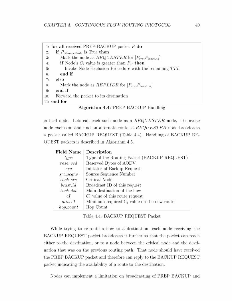
CHAPTER 4. CONTINUOUS FLOW ROUTING PROTOCOL 40
1: for all received PREP BACKUP packet P do2: if PisSourceSide is True then3: Mark the node as REQUESTER for [Psrc,Pbcast id]4: if Node’s Ci value is greater than PcI then5: Invoke Node Exclusion Procedure with the remaining TTL6: end if7: else8: Mark the node as REPLIER for [Psrc,Pbcast id]9: end if
10: Forward the packet to its destination11: end for
Algorithm 4.4: PREP BACKUP Handling
critical node. Lets call each such node as a REQUESTER node. To invoke
node exclusion and find an alternate route, a REQUESTER node broadcasts
a packet called BACKUP REQUEST (Table 4.4). Handling of BACKUP RE-
QUEST packets is described in Algorithm 4.5.
Field Name Descriptiontype Type of the Routing Packet (BACKUP REQUEST)
reserved Reserved Bytes of AODVsrc Initiator of Backup Request
src seqno Source Sequence Numberback src Critical Nodebcast id Broadcast ID of this requestback dst Main destination of the flow
cI Ci value of this route requestmin cI Minimum required Ci value on the new route
hop count Hop Count
Table 4.4: BACKUP REQUEST Packet
While trying to re-route a flow to a destination, each node receiving the
BACKUP REQUEST packet broadcasts it further so that the packet can reach
either to the destination, or to a node between the critical node and the desti-
nation that was on the previous routing path. That node should have received
the PREP BACKUP packet and therefore can reply to the BACKUP REQUEST
packet indicating the availability of a route to the destination.
Nodes can implement a limitation on broadcasting of PREP BACKUP and

CHAPTER 4. CONTINUOUS FLOW ROUTING PROTOCOL 41
BACKUP REQUEST packets using the TTL field of the IP header. This field
can initially be set to a certain value (3 in our case) when the PREP BACKUP
packet is initiated. Then each node receiving the packet will decrement the field
value by one before forwarding (broadcasting) it further. Finally, the TTL value
will reach to zero and the packet will be dropped at that node and will not be
forwarded anymore. When a node receiving PREP BACKUP packet broadcasts
a BACKUP REQUEST, it transfers the the remaining TTL value and range of
BACKUP REQUEST packet is limited on the nodes far away from the critical
node. This limits the reach of BACKUP REQUEST broadcast packets and can
help in reducing the overhead that Backup Route Mechanism imposes over the
network.
A BACKUP REQUEST packet has a special field called min cI. This field is
used to guarantee that all of the nodes on the new backup path (re-routing path)
will have Ci values that are greater than the Ci value of the critical node. This
way backup paths will always be better than the current path that we want to
change. Otherwise there is no meaning in changing the path.
1: for all received BACKUP REQUEST packet P do2: if Ci of node is greater than Pmin cI then3: if Node is not marked for [Psrc,Pbcast id] then4: Mark the node as INTHEMIDDLE for [Psrc,Pbcast id]5: Update PcI according to node’s Ci value6: Broadcast P again {Search again}7: else if Node is marked as REPLIER for [Psrc,Pbcast id] then8: Send a BACKUP REPLY packet to Psrc {Backup route is found}9: end if
10: end if11: end for
Algorithm 4.5: BACKUP REQUEST Handling
In node exclusion procedure, nodes construct routes to node Pback dst (main
destination of the flow), but send replies to node Psrc (the initiator of BACKUP
REQUEST) instead of the main source of the flow, so that newly constructed
routes modify the whole path between main source and destination, but only
deal with small portion of nodes.
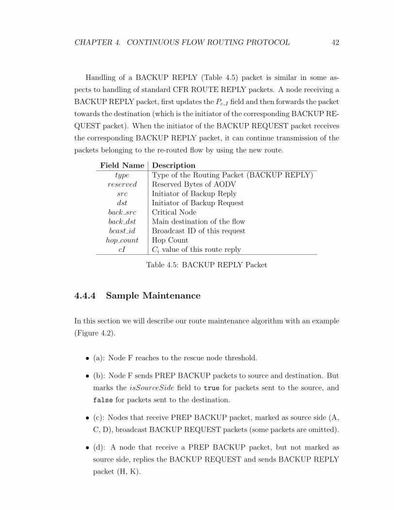
CHAPTER 4. CONTINUOUS FLOW ROUTING PROTOCOL 42
Handling of a BACKUP REPLY (Table 4.5) packet is similar in some as-
pects to handling of standard CFR ROUTE REPLY packets. A node receiving a
BACKUP REPLY packet, first updates the Pc I field and then forwards the packet
towards the destination (which is the initiator of the corresponding BACKUP RE-
QUEST packet). When the initiator of the BACKUP REQUEST packet receives
the corresponding BACKUP REPLY packet, it can continue transmission of the
packets belonging to the re-routed flow by using the new route.
Field Name Descriptiontype Type of the Routing Packet (BACKUP REPLY)
reserved Reserved Bytes of AODVsrc Initiator of Backup Replydst Initiator of Backup Request
back src Critical Nodeback dst Main destination of the flowbcast id Broadcast ID of this request
hop count Hop CountcI Ci value of this route reply
Table 4.5: BACKUP REPLY Packet
4.4.4 Sample Maintenance
In this section we will describe our route maintenance algorithm with an example
(Figure 4.2).
• (a): Node F reaches to the rescue node threshold.
• (b): Node F sends PREP BACKUP packets to source and destination. But
marks the isSourceSide field to true for packets sent to the source, and
false for packets sent to the destination.
• (c): Nodes that receive PREP BACKUP packet, marked as source side (A,
C, D), broadcast BACKUP REQUEST packets (some packets are omitted).
• (d): A node that receive a PREP BACKUP packet, but not marked as
source side, replies the BACKUP REQUEST and sends BACKUP REPLY
packet (H, K).

CHAPTER 4. CONTINUOUS FLOW ROUTING PROTOCOL 43
• (e): Route is modified and the node F is excluded from the path.
A
B
D
C
E
F
GI
H
K
J
PB [false]PB [false]
PB [true]
PB [true]
PB [true]
A
B
D
C
E
F
GI
H
K
J
(a) (b)
A
B
D
C
E
F
GI
H
K
J
A
B
D
C
E
F
GI
H
K
J
(c) (d)A
B
D
C
E
F
GI
H
K
J
(e)
Figure 4.2: A sample CFR route maintenance
4.5 Discussions on CFR
Although we have implemented a complete route discovery and maintenance pro-
tocol, some revisions may be required to have optimal performance.
We use the Ci value on all of our routing packets to have the cost of paths
on all intermediate nodes. The Ci field is filled on source and destination, and
CHAPTER 4. CONTINUOUS FLOW ROUTING PROTOCOL 44
updated on intermediate nodes, but do we really need to use Ci of source and
destination? If a source node have a little Ci value and tries to find a path to
the destination, all alternative paths will have a Ci value less than or equal to Ci
of the source. Then as all paths will have nearly equal Ci values, source can not
select the path with maximum lifetime.
CFR selects paths that have minimal Ci value, but it doesn’t have a special
solution for having two paths with the same Ci value. Modifying the route selec-
tion algorithm to prefer shortest paths on equal (or in epsilon range) Ci values,
will construct shorter paths and increase the overall lifetime of the network.
CFR protocol is tested and verified by a detailed simulator. All packets and
algorithms are implemented nearly equal to the real implementation and their
behavior is verified with code debugging and trace files. The evaluation and
success rate of the protocol will be described in the next section.

Chapter 5
Evaluation
We implemented the CFR protocol as part of a simulator. The implementation
proved the correctness of the protocol and shows that it is feasible to implement
the protocol as part of an ad hoc network. Then we evaluated the proposed
solution using the simulator. We did extensive simulation experiments. In this
section we will report the results of those experiments and our findings. We will
first describe our simulator.
5.1 Simulator
There are different ways of evaluating a new protocol. We can implement it on
a real testbed, simulate it, or use mathematical models to analyze it. Since the
implementation requires many ad hoc computers to use and therefore is costly,
we decided to use simulation as our evaluation methodology.
We had two options to develop a simulator for simulating our protocol:
• Writing a simulator from scratch: This is generally the most difficult road
to take. Since the simulator should be detailed enough to capture the real-
life system and scenario, it will take too much time and effort to develop
45
CHAPTER 5. EVALUATION 46
such a detailed simulator. All common algorithms and components used in
many simulators have to implemented as well, such as the event processing
engine.
• Using a simulation library or platform: There are many simulation libraries
available providing the essential components already. A simulator then can
be written using such a library, implementing only the parts necessary to
simulate the protocol. But in this case, the developer should spend time on
learning how to use the features of the library and also he/she is restricted
with the capabilities of the library. If the library is not open source, those
capabilities can not be modified.
We decided to follow the second approach. Since we would like to simu-
late a wireless ad hoc network routing protocol, it would be better if we have a
tool/library simulating wireless channels and low level protocols related to wire-
less links, like the MAC protocol. Additionally, since we are interested in per-
formance metrics like average packet delay, jitter, etc.; our simulator should be a
packet-based simulator (instead of being a flow based simulator). A packet-based
simulator keeps track of every packet sent in the network. Hence it can give
quite detailed results. But some other course-grained simulator, like a flow-based
simulator, can just simulate the establishment of flows with some duration, but
can not simulate the behaviour of packets, hence can not give the detailed results
that we are seeking.
Therefore, we selected NS-2 (The Network Simulator) [8] as the base simula-
tor into which we implemented our protocol. It is a widely accepted and trusted
simulator.
NS-2 is an open-source software developed with C++. It enables scripting
with TCL language and supports new protocol implementations. NS-2 is devel-
oped for simulating computer networks and have many ready-to-use features that
simulate real-world networks accurately.
NS-2 has built-in support for simulation of ad hoc networks. CMU Monarch
Group [4] implemented many ad hoc routing protocols into NS-2 and have made
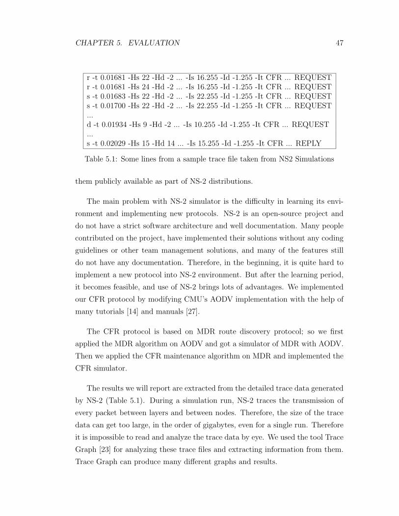
CHAPTER 5. EVALUATION 47
r -t 0.01681 -Hs 22 -Hd -2 ... -Is 16.255 -Id -1.255 -It CFR ... REQUESTr -t 0.01681 -Hs 24 -Hd -2 ... -Is 16.255 -Id -1.255 -It CFR ... REQUESTs -t 0.01683 -Hs 22 -Hd -2 ... -Is 22.255 -Id -1.255 -It CFR ... REQUESTs -t 0.01700 -Hs 22 -Hd -2 ... -Is 22.255 -Id -1.255 -It CFR ... REQUEST...d -t 0.01934 -Hs 9 -Hd -2 ... -Is 10.255 -Id -1.255 -It CFR ... REQUEST...s -t 0.02029 -Hs 15 -Hd 14 ... -Is 15.255 -Id -1.255 -It CFR ... REPLY
Table 5.1: Some lines from a sample trace file taken from NS2 Simulations
them publicly available as part of NS-2 distributions.
The main problem with NS-2 simulator is the difficulty in learning its envi-
ronment and implementing new protocols. NS-2 is an open-source project and
do not have a strict software architecture and well documentation. Many people
contributed on the project, have implemented their solutions without any coding
guidelines or other team management solutions, and many of the features still
do not have any documentation. Therefore, in the beginning, it is quite hard to
implement a new protocol into NS-2 environment. But after the learning period,
it becomes feasible, and use of NS-2 brings lots of advantages. We implemented
our CFR protocol by modifying CMU’s AODV implementation with the help of
many tutorials [14] and manuals [27].
The CFR protocol is based on MDR route discovery protocol; so we first
applied the MDR algorithm on AODV and got a simulator of MDR with AODV.
Then we applied the CFR maintenance algorithm on MDR and implemented the
CFR simulator.
The results we will report are extracted from the detailed trace data generated
by NS-2 (Table 5.1). During a simulation run, NS-2 traces the transmission of
every packet between layers and between nodes. Therefore, the size of the trace
data can get too large, in the order of gigabytes, even for a single run. Therefore
it is impossible to read and analyze the trace data by eye. We used the tool Trace
Graph [23] for analyzing these trace files and extracting information from them.
Trace Graph can produce many different graphs and results.

CHAPTER 5. EVALUATION 48
We implemented scripts that run the simulator for different scenarios and
random number seeds (Algorithm 5.1). For the output of the Trace Graph tool,
we implemented a small software that reads files for different seeds of a scenario
and protocol, and calculates the average values. Then we used these average
values as part of results we report in this chapter.
1: for all Simulation Scenarios S do2: for all Protocols P (CFR, AODV, MDR) do3: for seed = 1 to n do4: Run NS with P for S on seed5: Run Trace Graph on output of NS-26: Store Trace Graph output7: Delete trace files of NS-28: end for9: end for
10: end for
Algorithm 5.1: Simulation Script
5.2 Scenarios
We evaluated our protocol by comparing it to the other similar ones for the same
set of scenarios and parameters. We compared CFR against base AODV [26], and
MDR [19] with AODV. All of the scenarios are repeated with the same parameters
for all three protocols.
As the initial energies of nodes, in all scenarios, we used a random value to
better reflect the real-life case. All of the nodes except the source and destination
of the flows, have an initial energy between 0.01 Joules to 100.0 Joules. All the
source and destination nodes are given 40.0 Joule of initial energy to prevent a
failure during transmission.
We used a fixed seed for the random number generator to get the same network
environment for all the algorithms and to compare them in an equal setting; but
we repeated the simulations with different seed values and we averaged the results.
We report these average values in next chapter.
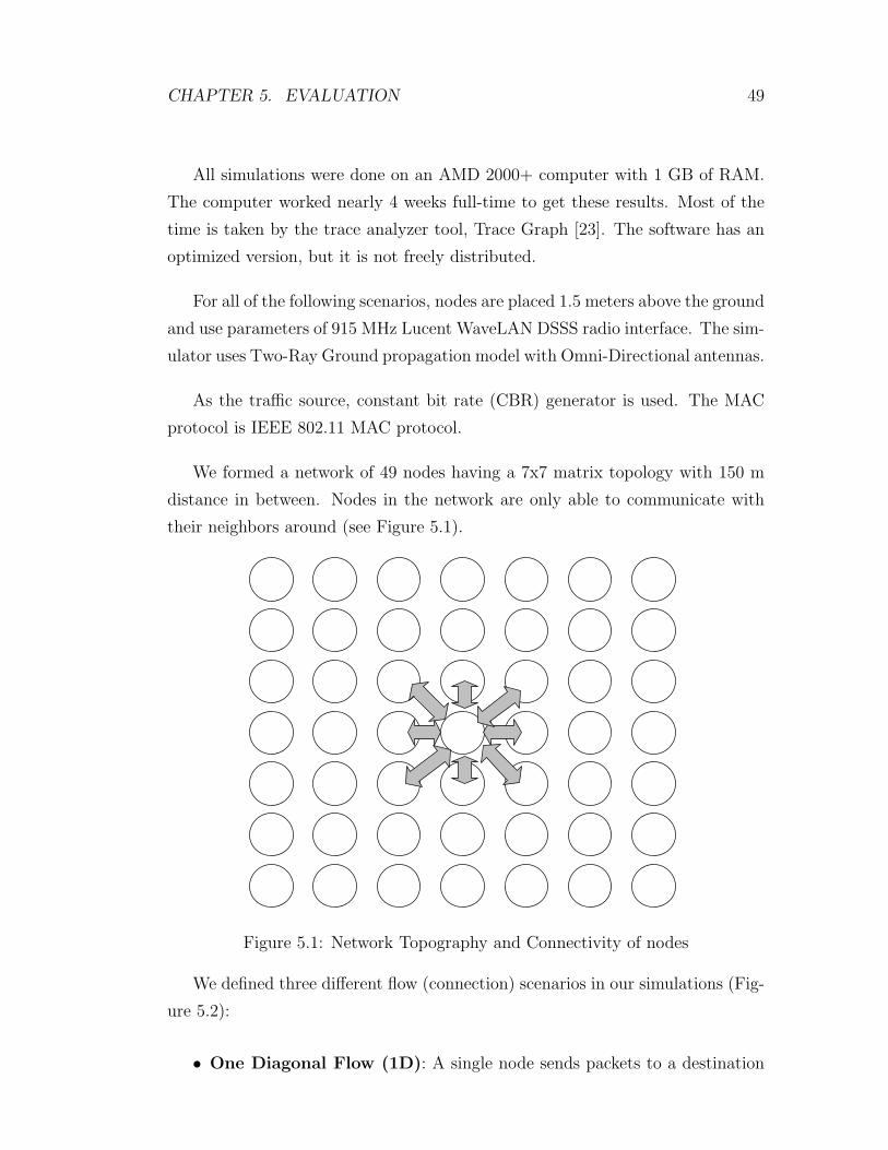
CHAPTER 5. EVALUATION 49
All simulations were done on an AMD 2000+ computer with 1 GB of RAM.
The computer worked nearly 4 weeks full-time to get these results. Most of the
time is taken by the trace analyzer tool, Trace Graph [23]. The software has an
optimized version, but it is not freely distributed.
For all of the following scenarios, nodes are placed 1.5 meters above the ground
and use parameters of 915 MHz Lucent WaveLAN DSSS radio interface. The sim-
ulator uses Two-Ray Ground propagation model with Omni-Directional antennas.
As the traffic source, constant bit rate (CBR) generator is used. The MAC
protocol is IEEE 802.11 MAC protocol.
We formed a network of 49 nodes having a 7x7 matrix topology with 150 m
distance in between. Nodes in the network are only able to communicate with
their neighbors around (see Figure 5.1).
Figure 5.1: Network Topography and Connectivity of nodes
We defined three different flow (connection) scenarios in our simulations (Fig-
ure 5.2):
• One Diagonal Flow (1D): A single node sends packets to a destination
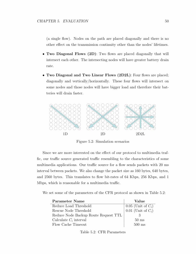
CHAPTER 5. EVALUATION 50
(a single flow). Nodes on the path are placed diagonally and there is no
other effect on the transmission continuity other than the nodes’ lifetimes.
• Two Diagonal Flows (2D): Two flows are placed diagonally that will
intersect each other. The intersecting nodes will have greater battery drain
rate.
• Two Diagonal and Two Linear Flows (2D2L): Four flows are placed;
diagonally and vertically/horizontally. These four flows will intersect on
some nodes and those nodes will have bigger load and therefore their bat-
teries will drain faster.
1D 2D 2D2L
Figure 5.2: Simulation scenarios
Since we are more interested on the effect of our protocol to multimedia traf-
fic, our traffic source generated traffic resembling to the characteristics of some
multimedia applications. Our traffic source for a flow sends packets with 20 ms
interval between packets. We also change the packet size as 160 bytes, 640 bytes,
and 2560 bytes. This translates to flow bit-rates of 64 Kbps, 256 Kbps, and 1
Mbps, which is reasonable for a multimedia traffic.
We set some of the parameters of the CFR protocol as shown in Table 5.2:
Parameter Name ValueReduce Load Threshold 0.05 (Unit of Ci)Rescue Node Threshold 0.01 (Unit of Ci)Reduce Node Backup Route Request TTL 3Calculate Ci interval 50 msFlow Cache Timeout 500 ms
Table 5.2: CFR Parameters

CHAPTER 5. EVALUATION 51
5.3 Results
5.3.1 End-to-End Delay
End-to-end delay is the time spent between a packet’s transmission from the
source and its arrival to the destination. The end-to-end delay gets affected from
many things: network condition, link states, buffer states, traffic load, the MAC
protocol, and the routing protocol. Here we are interested in the effect of routing
protocol on the end-to-end delay packets experience. In ad hoc networks, the
routing protocol is responsible for selecting the paths; and the lengths of the
paths, the current conditions of the paths, route failures and re-routing all affect
the end-to-end delay.
In this thesis, we propose a routing algorithm whose primary objective is not
to select the shortest paths, but to select paths that are more stable. Hence when
there is no route failures, the average end-to-end delays the packets experience
may be little bit larger than the protocols that always select minimum-hop paths,
or minimum-delay paths. However, considering also the route failures, a protocol
that tries to minimize the route failures can also gain advantage for the average
end-to-end delay, since each route failure increases the delay packets experience
during the respective route repair. Therefore it is not always obvious which
protocol will perform better in terms of average end-to-end delay without doing
a careful simulation study.
As Figure 5.3 shows, CFR and MDR give better results than base AODV
routing protocol in terms of end-to-end delay. Both of these protocols try to find
more stable routes, and in a scenario where we have route failures in a quite big
network, the benefit of stability comes into picture and we observe lower average
end-to-end delay. However, if we compare CFR and MDR there is no significant
difference between them in terms of end-to-end delay.
The success of CFR and MDR compared to base AODV is more clearly seen
when we examine the maximum (worst case) end-to-end delay. Figure 5.4 shows
the differences for different number of flows and packet sizes. The maximum delay

CHAPTER 5. EVALUATION 52
Average Delay
0
0,5
1
1,5
2
2,5
160 640 2560Packet Size(bytes)
Seco
nds AODV
CFRMDR
1D
Average Delay
00,20,40,60,8
11,21,41,61,8
160 640 2560Packet Size(bytes)
Seco
nds AODV
CFRMDR
2D
Average Delay
0
0,5
1
1,5
2
2,5
160 640 2560Packet Size(bytes)
Seco
nds AODV
CFRMDR
2D2L
Figure 5.3: Average Delay Results
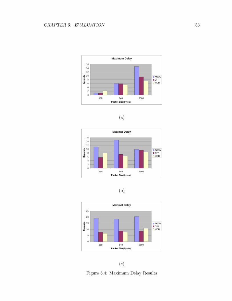
CHAPTER 5. EVALUATION 53
Maximum Delay
0
2
4
6
8
10
12
14
16
160 640 2560Packet Size(bytes)
Seco
nds AODV
CFRMDR
(a)
Maximal Delay
0
2
4
6
8
10
12
14
16
160 640 2560Packet Size(bytes)
Seco
nds AODV
CFRMDR
(b)
Maximal Delay
0
5
10
15
20
25
160 640 2560Packet Size(bytes)
Seco
nds AODV
CFRMDR
(c)
Figure 5.4: Maximum Delay Results

CHAPTER 5. EVALUATION 54
is large in AODV, because base AODV does not apply a proactive maintenance
algorithm, and this may incur too high delay on packets when a route fails and
route discovery is started to find a new route. During this time, packets can be
lost as well, if buffers are filled up. In CFR, we follow a proactive approach and
find a new route before an existing route completely fails.
The difference between AODV and other protocols on average delay is not as
big as on maximum delay, because AODV always finds shortest available paths
and other protocols try to find the most stable routes which can be longer.
Compared to MDR, CFR does better in some scenarios but does nearly equal
in some others because its route discovery scheme is an adapted version of MDR.
CFR implements maintenance on MDR.
5.3.2 Delay Jitter
Delay jitter is variation in end-to-end delay. If the end-to-end delay is fixed, it is
easy to handle; but if it varies, then the audio/video player at the received side
should compensate for the jitter while playing the media. For this compensation,
a jitter buffer can be used. A higher jitter requires a bigger buffer. Therefore it
is better if we have low jitter for packets.
Any change in a network condition, or a route failure affects the delay expe-
rienced by packets of an ongoing flow; therefore generates jitter. If we reduce the
variations on network conditions, or route failures, then we can also stabilize the
jitter. Hence we expect lower jitter for protocols that are more stable.
This is indeed what we observe in our results. As shown in Figure 5.5, base
AODV protocol has much larger jitter than CFR and MDR protocols, since base
AODV does not apply a proactive route maintenance scheme. Whenever a route
failure occurs, it starts route discovery again at that time. This causes too much
delay for packets that are generated at the source at the time of new route dis-
covery.

CHAPTER 5. EVALUATION 55
Average Jitter
00,020,040,060,080,1
0,120,140,160,18
160 640 2560Packet Size(bytes)
Seco
nds AODV
CFRMDR
1D
Average Jitter
0
0,05
0,1
0,15
0,2
0,25
0,3
160 640 2560Packet Size(bytes)
Seco
nds AODV
CFRMDR
2D
Average Jitter
00,050,1
0,150,2
0,250,3
0,350,4
0,45
160 640 2560Packet Size(bytes)
Seco
nds AODV
CFRMDR
2D2L
Figure 5.5: Average Jitter Results

CHAPTER 5. EVALUATION 56
CFR does better than MDR on some cases. CFR is more successful on jit-
ter results, because its maintenance algorithm pro-actively protects flows from
getting disturbed from route breaks.
In the following figures, we show the packet-delay versus time graphs, so
that we can have an understanding of how the delay changes over time while a
simulation run is executed. We first show the results for 1D flow; then for 2D
flows.
Figure 5.6 shows the delay versus time graphs for the scenario where we have
only one flow for all three algorithms. As can be seen from the figure, the CFR
protocol causes high delay values only during the initialization time. But in
AODV and MDR we see many peaks in the graphs indicating high packet delays
from time to time.
Figure 5.7 shows the delay versus time for the scenario where we have two
flows in the network. This time CFR also has peaks, but not that much as AODV
or MDR.
5.3.3 Packet Loss
Packets may dropped/lost in a network due to several reasons: a) collisions may
occur at the MAC layer; b) unrecoverable bit errors may occur during transmis-
sion through a channel; c) buffers on nodes may get filled up and can not hold
new incoming packets.
The operation of a routing algorithm can be effective in triggering the reason
c). During a route failure, the packets generated by the source node will not be
routed until the new route is constructed. Additionally, when the source node
(or the node requesting backup route) understands that a failure has occurred, it
can stop sending packets, and this will cause its buffer to fill up, and finally the
packets generated by the traffic source will not be stored in the buffer and will
be dropped.

CHAPTER 5. EVALUATION 57
Time Versus Delay
0
0,1
0,2
0,3
0,4
0,5
0,6
0,7
Time
Del
ay
(a)
Time Versus Delay
0
0,05
0,1
0,15
0,2
0,25
0,3
Time
Del
ay
(b)
Time Versus Delay
0
0,2
0,4
0,6
0,8
1
1,2
1,4
Time
Del
ay
(c)
Figure 5.6: Time vs. Delay Values on 1D Simulations ( a: CFR b: AODV c:MDR)

CHAPTER 5. EVALUATION 58
Time Versus Delay
0
2
4
6
8
10
12
14
16
Time
Del
ay
(a)
Time Versus Delay
0
2
4
6
8
10
12
14
16
Time
Del
ay
(b)
Time Versus Delay
0
1
2
3
4
5
6
7
8
9
10
Time
Del
ay
(c)
Figure 5.7: Time vs. Delay Values on 2D Simulations ( a: CFR b: AODV c:MDR)
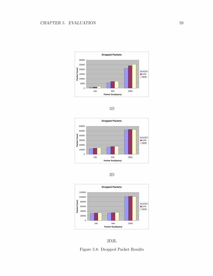
CHAPTER 5. EVALUATION 59
Dropped Packets
0
5000
10000
15000
20000
25000
30000
160 640 2560Packet Size(bytes)
Pack
et C
ount
AODVCFRMDR
1D
Dropped Packets
0
10000
20000
30000
40000
50000
60000
160 640 2560Packet Size(bytes)
Pack
et C
ount
AODVCFRMDR
2D
Dropped Packets
0
20000
40000
60000
80000
100000
120000
160 640 2560Packet Size(bytes)
Pack
et C
ount
AODVCFRMDR
2D2L
Figure 5.8: Dropped Packet Results

CHAPTER 5. EVALUATION 60
We expect a routing protocol that is more stable to have less packet losses.
But this is not something that we observed in our simulation results. We observed
that all of three protocols we simulated have similar number of packet losses. This
was not something that we expected. This may be due to the scenarios that we
have used. Those scenarios may not have caused a heavy buffer overflow at the
source due to route failures. This is something we will investigate further as part
of future work.
5.3.4 Routing Control Packet Overhead
For a routing protocol, route construction and maintenance requires some control
and management packets to be sent and received. This is the overhead imposed
on the network, since those packets do not carry user information. For any routing
protocol, routing overhead should not be too large. Otherwise, it means we are
not utilizing the network resources well.
We measured the number of routing related control messages sent in the net-
work for all the three routing algorithms that we compare. Figure 5.9 shows the
results.
As the Figure shows, the AODV protocol, that does not apply a proactive
route maintenance, has the least overhead. This is an expected result since AODV
protocol is not using control packets for proactive maintenance and uses shorter
paths during route discovery. The overhead of CFR and MDR protocols, on the
other hand, are nearly the same, but CFR performs slightly better.
5.3.5 Effect of Packet Inter-Arrival Time
Previous results are taken while packet inter-arrival time is fixed to 20 ms. Packet
inter-arrival time affects the rate of traffic injected into the network, therefore can
be effective in filling the buffers sooner, causing more collisions, and increase the
delay further. This is indeed what we observe in our results which are shown in

CHAPTER 5. EVALUATION 61
Routing Packets
0
5000
10000
15000
20000
25000
30000
160 640 2560Packet Size(bytes)
Pack
et C
ount
AODVCFRMDR
1D
Routing Packets
0
10000
20000
30000
40000
50000
60000
160 640 2560Packet Size(bytes)
Pack
et C
ount
AODVCFRMDR
2D
Routing Packets
0
10000
20000
30000
40000
50000
60000
70000
160 640 2560Packet Size(bytes)
Pack
et C
ount
AODVCFRMDR
2D2L
Figure 5.9: Routing Overhead Results
CHAPTER 5. EVALUATION 62
Figure 5.10.
To speed-up simulations to get these results, we used 16 nodes which have a
4x4 matrix topology, with 0.01 to 10 joules of energy on nodes. We used the 2D
scenario where we have two flows in the network.
As the figure shows, when the interval gets smaller (more traffic), the average
delay and jitter increases. For this particular result, we see that AODV performs
better when the interval is quite small. In this case we used a small network
where the average path length is very small. Therefore, AODV can establish a
new route very fast and we don’t see the benefit of proactive maintenance. But
when interval gets bigger, we again see that AODV has much larger average delay
and jitter with respect to the two other protocols.
5.3.6 Results with Randomly Located Flows
We also wanted to observe results if we use random flows generated at arbitrary
nodes in the network. In this scenario, we used a 50-nodes network. We con-
struct 3 random node placements with 3 different connection patterns and run
all combinations with 5 different seeds. Table 5.3 presents the results.
Measure AODV CFR MDR
Average Delay (sec) 0.382 0.329 0.342Maximum Delay (sec) 3.635 2.363 2.107Average Jitter (sec) 0.0575 0.0569 0.0492Dropped Packets (packets) 13676 14011 13836Routing Packets (packets) 976 1462 1395
Table 5.3: Random Scenario Results
With random scenarios, we have the same conclusion that we have from our
previous results. AODV has higher delay and jitter. CFR and MDR has nearly
the same delay and jitter. CFR delay result is slightly better. The overhead of
AODV is less than the overhead of CFR and MDR.
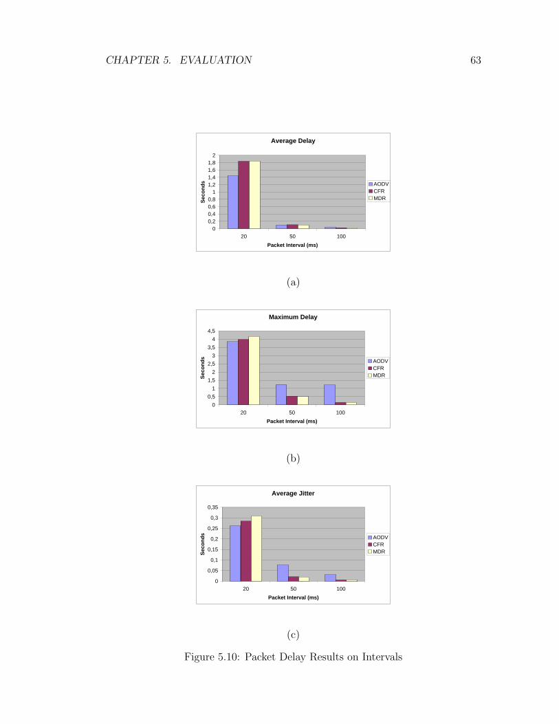
CHAPTER 5. EVALUATION 63
Average Delay
00,20,40,60,8
11,21,41,61,8
2
20 50 100Packet Interval (ms)
Seco
nds AODV
CFRMDR
(a)
Maximum Delay
00,5
11,5
22,5
33,5
44,5
20 50 100Packet Interval (ms)
Seco
nds AODV
CFRMDR
(b)
Average Jitter
0
0,05
0,1
0,15
0,2
0,25
0,3
0,35
20 50 100Packet Interval (ms)
Seco
nds AODV
CFRMDR
(c)
Figure 5.10: Packet Delay Results on Intervals

Chapter 6
Conclusion and Future Work
6.1 Conclusion
In this thesis we propose an ad hoc network route discovery and maintenance
solution (called CFR) which aims to support multimedia applications by reducing
the adverse affects of route failures and high load on these applications. The
proposed solution tries to find stable routes. A stable route is defined as the route
with maximum lifetime left, considering the current energy levels and current
battery drain rates of the nodes on the route.
CFR protocol finds routes with maximum lifetime during route discovery
phase and also implements a proactive route maintenance scheme that re-routes
multimedia flows from paths with low energy so that the flows are not disturbed
by nodes that have very few energy left and will die soon. To decide when to
trigger the maintenance, the protocol uses two different thresholds. One is used
to distribute a high load that a node has to its neighbors; the other is used to
re-route the whole traffic (all flows) that a node has through its neighbors or some
other paths. The study proposes a scheme for finding alternative better routes
when a flow has to be re-routed.
We evaluated our proposed protocol via simulation. We implemented the
64

CHAPTER 6. CONCLUSION AND FUTURE WORK 65
protocol as part of the NS-2 simulation environment and did extensive tests for
testing whether the protocol is working correctly or not. After verifying and val-
idating the protocol and its simulation, we did extensive simulation experiments
to evaluate the protocol and compare it against some other similar protocols,
such as AODV and MDR.
The simulation results show that, CFR and MDR together have better results
than AODV in terms of average packet and jitter. However, AODV incurs less
overhead on the network since it does not implement a proactive maintenance
procedure. CFR is better in some cases compared to MDR; but in some other
cases they perform very close to each other; and in some cases MDR performs
better. In short, simulation results indeed show that CFR can be a good candidate
as a routing and maintenance protocol that supports multimedia traffic in a
wireless ad hoc network.
6.2 Future Work
We see many issues about CFR that can be improved with further study.
CFR is a routing protocol for optimizing route performance depending on the
energy state of nodes in the network, but energy is not the only problem for an ad
hoc network. They generally consist of mobile nodes, which we didn’t consider in
CFR protocol. Finding most stable routes requires finding paths which consists
of most stable nodes. CFR route discovery and maintenance protocol can be
extended to have mobility in mind. Using mobility detection and active node
selection procedure of ARMP [3], we can extend CFR to have stable routes that
are resistant to node movements.
The thresholds and the lifetime calculation period for nodes are set to some
fixed values in the currrent protocol implementation. An adaptive scheme, how-
ever, can be applied and this may improve the performance and the ability of the
protocol to adapt to changing network conditions.

CHAPTER 6. CONCLUSION AND FUTURE WORK 66
In CFR, there is no collaboration among nodes to implement a better mainte-
nance. There are some cases where individual route maintenance may harm the
network, or collaboration may find better backup routes:
A
B
D
C
E
F
GI
H
K
J
A
B
D
C
E
F
GI
H
K
J
(a) (b)
Figure 6.1: A sample for overlapping backup routes: (a) Initial route with twocritical route, (b) After maintenance is applied
• Finding backup for two nodes: If two nodes on a route require a maintenance
procedure at the same time, then a single backup route that covers both
of the nodes might be more efficient. In current situation, the protocol
triggers two backup routing finding operations, hence will lead to two new
sub-routes to be established.
• Overlapping backup routes: Two nodes on a route may initiate a mainte-
nance process and their backup routes may overlap (Figure 6.2).
A
B
D
C
E
F
GI
H
K
J
A
B
D
C
E
F
GI
H
K
J
(a) (b)
Figure 6.2: A sample for fluctuation of backup routes: (a) Node F has a high load,calls maintenance, (b) Now node G has a high load and it will call maintenance

CHAPTER 6. CONCLUSION AND FUTURE WORK 67
• Fluctuation in backup route finding process: A node with high load will
request a maintenance and reduce its load, but this time a neighboring
node might get a high load and initiate another maintenance, which will
send more traffic to the first node again. This can continue causing a
fluctuation of routes (Figure 6.2).
We can also improve our evaluation of CFR protocol to better reflect the
network characteristics and increase the understanding of protocols.
CFR is implementing a stability solution for energy levels of nodes, but what
about total energy level of the network. MTPR [29] tries to reduce the total
cost of a route on the network, but CFR and most of the other routing protocols
do not care the total network energy. We could evaluate our protocols with the
change in the total energy level and see their performance. This kind of a graph
could introduce very interesting results and let us discuss our protocols with a
different aspect.
In our evaluation we measured the packet loss rate and got the nearly same
results on all protocols. But according to special handling mechanisms of CFR
and MDR this shouldn’t be the case. In a network a packet can be dropped
because of:
• Buffer Overflow
• Node Failure
• Channel Error
• MAC Collisions
The number of packets dropped by these reasons should be different on our
simulations. We should look at the trace files and investigate the reasons of packet
drops to better understand the characteristics of our protocols.
Bibliography
[1] S. Agarwal, A. Ahuja, J. Singh, and R. Shorey. Route-lifetime assessment
based routing (RABR) protocol for mobile ad-hoc networks. Communica-
tions, 2000. ICC 2000. 2000 IEEE International Conference on, 3:1697–
1701, 2000.
[2] H. Balakrishnan, V. Padmanabhan, S. Seshan, and R. Katz. A comparison of
mechanisms for improving TCP performance over wireless links. IEEE/ACM
Transactions on Networking (TON), 5(6):756–769, 1997.
[3] C. Chang and S. Tu. Active route-maintenance protocol for signal-based
communication path in ad hoc networks. Journal of Network and Computer
Applications, 25(3):161–177, 2002.
[4] CMU Monarch Group, http://monarch.cs.cmu.edu/cmu-ns.html. CMU
Monarch extentions to the NS-2 simulator, 1998.
[5] B. Crow, I. Widjaja, L. Kim, and P. Sakai. IEEE 802.11 Wireless Local Area
Networks. Communications Magazine, IEEE, 35(9):116–126, 1997.
[6] R. Dube, C. Rais, K. Wang, and S. Tripathi. Signal stability-based adaptive
routing (SSA) for ad hoc mobile networks. IEEE Personal Communications,
4(1):36–45, 1997.
[7] T. Dyer and R. Boppana. On routing Web and multimedia traffic in mobile
ad hoc networks. System Sciences, 2003. Proceedings of the 36th Annual
Hawaii International Conference on, page 10, 2003.
68

BIBLIOGRAPHY 69
[8] K. Fall and K. Varadhan. The ns Manual (formerly ns Notes and Docu-
mentation). The VINT Project, A Collaboration between researchers at UC
Berkeley, LBL, USC/ISI and Xerox PARC, November 2005.
[9] L. Feeney and M. Nilsson. Investigating the energy consumption of a wireless
network interface in an ad hoc networking environment. INFOCOM 2001.
Twentieth Annual Joint Conference of the IEEE Computer and Communi-
cations Societies. Proceedings. IEEE, 3:1548–1557, 2001.
[10] I. Gerasimov and R. Simon. Performance analysis for ad hoc QoS routing
protocols. Mobility and Wireless Access Workshop, 2002. MobiWac 2002.
International, pages 87–94, 2002.
[11] M. Gerharz, C. de Waal, M. Frank, and P. Martini. Link stability in mobile
wireless ad hoc networks. Local Computer Networks, 2002. Proceedings. LCN
2002. 27th Annual IEEE Conference on, pages 30–39, 2002.
[12] H. Gharavi and K. Ban. Dynamic adjustment packet control for video com-
munications over ad-hoc networks. Communications, 2004 IEEE Interna-
tional Conference on, 5:3086–3090, 2004.
[13] T. Goff, N. Abu-Ghazaleh, D. Phatak, and R. Kahvecioglu. Preemptive
routing in Ad Hoc networks. Proceedings of the 7th annual international
conference on Mobile computing and networking, pages 43–52, 2001.
[14] M. Greis. Tutorial for the Network Simulator “ns”. http://www.isi.edu/
nsnam/ns/tutorial/index.html.
[15] IEEE 802.11 Working Group, http://grouper.ieee.org/groups/802/
11/. IEEE 802.11 Specifications.
[16] Internet Engineering Task Force, Manet Working Group Charter, http://
www.ietf.org/html.charters/manet-charter.html. Ad Hoc Networks.
work in progress.
[17] D. Johnson, D. Maltz, and J. Broch. DSR: The Dynamic Source Routing
Protocol for Multi-Hop Wireless Ad Hoc Networks. Ad Hoc Networking,
pages 139–172, 2001.
BIBLIOGRAPHY 70
[18] M. Johnsson. HiperLAN/2–The Broadband Radio Transmission Technology
Operating in the 5 GHz Frequency Band. HiperLAN/2 Global Forum, 1999.
[19] D. Kim, J. Garcia-Luna-Aceves, K. Obraczka, J. Cano, and P. Manzoni.
Routing Mechanisms for Mobile Ad Hoc Networks Based on the Energy
Drain Rate. IEEE Transactions on Mobile Computing, 2(2):161–173, 2003.
[20] J. F. Kurose and K. W. Ross. Computer Networking, A Top-Down Approach
Featuring the Internet. Addison Wesley, 2001.
[21] R. LaMaire, A. Krishna, P. Bhagwat, and J. Panian. Wireless LANs and
mobile networking: standards and future directions. Communications Mag-
azine, IEEE, 34(8):86–94, 1996.
[22] S. Lee and M. Gerla. AODV-BR: backup routing in ad hoc networks.
Wireless Communications and Networking Conference, 2000. WCNC. 2000
IEEE, 3:1311–1316, 2000.
[23] J. Malek. Trace graph - Network Simulator NS-2 trace files analyser. http:
//www.tracegraph.com, 2006.
[24] S. Mao, S. Lin, S. Panwar, Y. Wang, and E. Celebi. Video transport over ad
hoc networks: multistream coding with multipath transport. Selected Areas
in Communications, IEEE Journal on, 21(10):1721–1737, 2003.
[25] C. S. R. Murthy and B. S. Manoj. Ad Hoc Wireless Networks, Architectures
and Protocols. Prentice Hall, 2004.
[26] C. Perkins and E. Royer. Ad-hoc on-demand distance vector routing. Pro-
ceedings of the 2nd IEEE Workshop on Mobile Computing Systems and Ap-
plications, 2, 1999.
[27] F. J. Ros and P. M. Ruiz. Implementing a New Manet Unicast Routing Proto-
col in NS2. Dept. of Information and Communications Engineering, Univer-
sity of Murcia, http://masimum.dif.um.es/nsrt-howto/html/, Dec 2004.
[28] E. Royer and C. Toh. A review of current routing protocols for ad hoc mobile
wireless networks. Personal Communications, IEEE [see also IEEE Wireless
Communications], 6(2):46–55, 1999.

BIBLIOGRAPHY 71
[29] K. Scott and N. Bambos. Routing and channel assignment for low power
transmission in PCS. Universal Personal Communications, Record., 5th
IEEE International Conference on, 2:498–502, 1996.
[30] C. Sengul. Local Route Recovery in Mobile Ad Hoc Networks. Master’s
thesis, Computer Science, Univ. of Illinois at Urbana-Champaign, 2003.
[31] S. Singh, M. Woo, and C. Raghavendra. Power-aware routing in mobile
ad hoc networks. Proceedings of the 4th annual ACM/IEEE international
conference on Mobile computing and networking, pages 181–190, 1998.
[32] C. Toh. Maximum battery life routing to support ubiquitous mobile com-
putingin wireless ad hoc networks. Communications Magazine, IEEE,
39(6):138–147, 2001.

Appendix A
Table of Acronyms
1D One Diagonal Flow
2D Two Diagonal Flows
2D2L Two Diagonal and Two Linear Flows
AMD Advanced Micro Devices
AODV Ad Hoc On-Demand Distance Vector Routing
ARMP Active Route Maintenance Protocol
CBR Constant Bit Rate
CFR Continuous Flow Routing
CMU Carnegie Mellon University
CSR Clusterhead Gateway Switch Routing
DSDV Destination-Sequenced Distance-Vector Routing
DSR Dynamic Source Routing
DSSS Direct-Sequence Spread Spectrum
FTP Filet Transfer Protocol
IEEE Institute of Electrical and Electronics Engineers
IP Internet Protocol
LAN Local Area Network
Kbps Kilobits per second
MAC Medium Access Control
Mbps Megabits per second
72

APPENDIX A. TABLE OF ACRONYMS 73
MDR Minimum Drain Rate Mechanism
MHz Megahertz
MMBCR Min-Max Battery Cost Routing
MTPR Minimum Total Transmission Power Routing
NS Network Simulator
QoS Quality of Service
RAM Random Access Memory
RTO Retransmit Timeout
SSA Signal Stability Based Adaptive Routing
TCL Tool Command Language
TCP Transmission Control Protocol
TORA Temporally Ordered Routing Algorithm
UDP User Datagram Protocol
WLAN Wireless Local Area Network
WRP The Wireless Routing Protocol


