
!?I8
H85


CONSTRUCTION AND STANDARDIZATION OF
SIX SELF INDUCTANCE COILS
BY
CHING LEE HSUN
B. A. University of Illinois, 1917.
THESIS
Submitted in Partial Fulfillment of the Requirements for the
Degree of
MASTER OF ARTS
IN PHYSICS
IN
THE GRADUATE SCHOOL
OF THE
UNIVERSITY OF ILLINOIS
1918

Digitized by the Internet Archive
in 2013
http://archive.org/details/constructionstanOOhsun

UNIVERSITY OF ILLINOISTHE GRADUATE SCHOOL
3.7. 191 8
1 hereby recommend that the thesis prepared under MY SUPER-
VISION BY CHING LEK H8UN
ENTITLED f!ONfiTFUOTTO,?I AND STANDARDIZATION CI S..LX SLELE.
TwnnflTAttrar httlls
BE ACCEPTED AS FULFILLING THIS PART OF THE REQUIREMENTS FOR THE
DEGREE OF MASTFtt 07 A^T? JL.*Z251C£.
Recommendation concurred in :*
Head of Department
Committee
on
Final Examination*
*Required for doctor's degree but not for master's.
408233
V J
TAPLF OF CONTENTS
Pasre
I INTRODUCTION 1
II CONSTRUCTION 1
ITT MEASUREMENT
1. Anderson's Method 2
Telephone U3ed as a Detector 7
The Alternating Current Calvanomet er. . 8
The Vi oration Galvanometer 9
2. Rimingtcn 1 s Method 10
3. CoiT.parison Met'bott ^14
B&chommeter 14
IV DISCUSSION OF METHODS 15
Hov»r Fork May be Further Improved 30

rig. l
I INTRODUCTION
A eoil containing self inductance has wide application in
daily life, in engineering ana in physics. We meet with it every-
where, for instance, the electromagnet, the electric call bell, t*e
telephone call tell, the l/crse relav, the t rar 3fcrrr er , the generator
the motor, the induction coil, etc. The range is very wide, frorr a
few millihenrv tc hundreds of henry. For many practical purposes
where a. large inductance is desired and where constancy is net im-
portant, the coil is wound on an iron core, very large values rrav v e
obtained since the inductance is directly proportional tc the perme-
ability of the iron cor?. Put when used as a standard fcr physical
measurement s, the coil should be wound on a wooden or ether non-
magnetic spool having an air core. Since the permeability of air is
unity the inductance is constant fcr all values of current employed.
The coefficient of self-inductance can be theoretically cal
culated in some simple cases; as fcr example, the inductance of a
long- solenoid, or of a transmission line, However, ir; most cases,
it must be actually measured.
TT CONSTRUCTION
Six spools having the fern and dimensions shewn in Fig. 1,
were turned in lathe. They were carefully smoothed and shellacked.
Six pairs of brass binding posts were made in the Physics Department
machine shop. A pair for each spool was mounted on the top near the
edge of the hole through the center and diametrically opposite ea.ch
other. The mounting of th--3 binding posts, however, came later after
the winding of the coil was finished. Number 30 F. S. cotton covered
copper wire was chosen to be wound on each spool. The winding was


carefully lone on the lathe. The two enda of the coil were brought
out through the small holes A and E respectively (Fig, 1), The man-
ner of mounting the two binding posts is as follows: A brass rod
about 2 1/4 inches long threaded at each end wa3 inserted through
holes in the spool. The top end was first screwed into ana sol-
dered to the bottom of the binding; post. Fach terminal cf the wire
having its insulation off was twisted around the brass red and firm-
ly clamped under the oinding post by means of a bras3 nut at the
bottom end of the rod. The rigidity cf the winding was reenforced
by soaking irith shellac. When dry the coils were ready to use.
Ill MEASUREMENT
1 Anderson's Method
Theory and Method. - The arrangement is similar to the
Wheatstone Bridge. The four resistances in the arms are P, R,
and S (Fig. 2). All the resistances except Q are non-inductive. Sup-
pose a balance has been obtained tcr steady currents by closing
before Kg. This balaice will not be disturb 3d by introducing the
resistance r between F and N, that is, in series with the galvanom-
eter. Adjust the capacity C and resistance r until the galvanometer
shows no kick for variable currents by closing K before K,
.
Let x be the quantity of electricity which has charged the
condenser at time t, z the quantity whijjh has passed through FL,
then x+z has passed through AF, and let y = the quantity of elec-
tricity through AL, L = the coefficient of self-inductance to be
measured.
Since the fall of potential is same by the two paths, one
through resistance R, the other through resistance r and condenser,

Fig. 3

Fig.

we have
Rdz x+
^az ( 1
)
It cT Mt
Again, N and H must be at the same potential sinca the bridge is
balanced
& m a&Z (3)c
bdt
Further, the change of potential frou. A through P to N must
be the same as frorr A to H. Hence
substituting from (l) and (b)
(r+P)dt
+P (
c+
*dt)=
SC+
SC dt
Rearranging the terms
EC + lM M R r;dt PC + SC dt
This equation expresses the conditions necessary for a balance with
both steady and variable currents. For the steady current balance,
it is only necessary to equate the coefficient of the constant part.
i. e. P _ &P " S
The last equation is the one that obtains ordinarily for the
Wheat stone bridge.
The other condition, namely, the one for a balance for vari-
able currents is found by equating the coefficient of dx; ordt
_ Pr Lr + p + R~
=SC
From whichL = C r(Q+S) + PS .
The arrangement of the apparatus for this method is as shown
in Fig. 3. The arm Q consisted of resistance q, 1:he resistance of

. 1

4
the inductance coil and the resistance of one side cf the bridge
wire. The arrr. S consisted cf s ana. the resistance of the other side
of the bridge wire. Since the coil was wound with copper wire, it
has a comparatively high temperature coefficient. The steady bal-
ance continually shifted due to the char. Te of temperature. This
trouble was very much reduced by placing the coil in a hairfelt
calorimeter.
The question naturally rises; How can a va.nable current be
obtained from a steady current voltage on closing Kg before K^?
Such phenomenon is known as growth of current when TC. M. F. is sudden-
ly applied to an inductive circuit. The E.M.F, is wholly used in
overcoming the resistance and the inductance of the circuit.
l|i + ir - eat
ai. - dt
3— lrL
i
Integrating both 3iaes
k is a constant, When t * i =
* Slog f - kr ° L
substituting
L - /e-ri* I»i _ ,e +
F is. 4
log e-ri . -£t
e-ri _ "I*L " s
Solving for i _-ft
i = £(l-e?J
)r
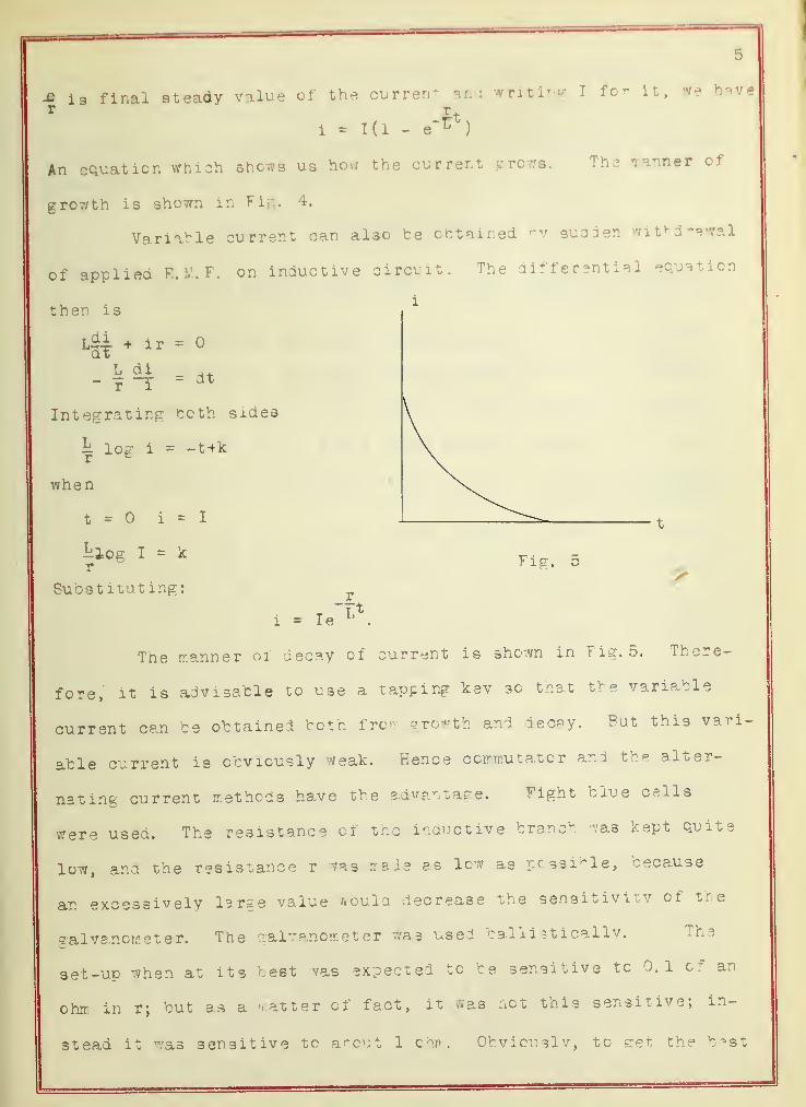
-fi li final steady value of the current and writing I for it, we have
1 - 1(1 - e'^)
An equation which shows us how the current grow*. The manner of
growth is shown in Fig. 4.
Variable current can al3o te obtained by sudden withdrawal
of applied R. H. f, on inductive circuit. The differential equation
then is
iM * ir H
L di= dt
r i
Integrating both sides
r
when
k log i = -t+k
t i = I
lilog I = kr
Substituting:
Fig. 5>
r
i = Ie
The manner of decay of current is shown in Fig. 5. There-
fore, it is advisable to use a tapping key so that the variable
current can be obtained both fro- growth and decay. But this vari-
able current is obviously weak. Hence commutator and the alter-
nating current methods have the advantage. Fight blue cells
were used. The resistance cf the inductive branch "/as kept quite
low, and the resistance r was made as lev as ppsaihle, because
an excessively large value would decrease the sensitivity cf the
galvanometer. The galvanometer was used balii at icallv. The
set-up when at its best was expected to be sensitive tc 0.1 of an
ohm in r; but as a matter of fact, it was not this sensitive; in-
stead it was sensitive to about 1 ohm. Obviouslv, to get the best


results, the test detector for variable current is required. The
detector is not only- limited to the a'Arscnval galvanometer; the
telephone, the alternating current galvanometer, and the vibration
galvanometer, may be employed.
DATA - ANDERSON'S MFTHOC
Coil No. P R q S b bp S C r Lohm ohm ohm ohm mm. ohm ohm. micro
faradohm. milli-
henry
A 1 300 300 8 16. 5 487 . 3064 16. 8064 5. 743 3. 4 29. 5993
2 300 30C 8 16. 5 485 . 3056 16. 8056 5. 643 6. 29. 5496
5 300 300 8 16. 5 485 . 3056 16. 8056 5. 443 12. 29. 6262
4 300 300 8 16. 5 484 . 3048 16. 8048 5. 243 18. 4 29. 7535
5 300 300 6 16. 5 484 . 3048 16. 8*8 4. 843 . 8
Mean39. 596429. 6254
B 1 210 210 2 6. 4 546 . 34*6 6. 745 6. 943 1 9. 9043
2 210 210 2 6. 4 546 . 3446 6. 745 6. 843 2. 4 9. 9825
3 210 210 2 6. 4 547 . 3446 6. 745 6. 743 3. 6 9. 9449
4 210 210 2 6. 4 547 . 3*46 6. 745 6. 643 4. 7 9. 8969
5 210 210 2 6. 4 547 , 3446 6. 745 6. 442 5. 8
Mean9. 88059. 9226
C 1 210 210 7 13.9 486 . 295 1*. 195 6. 97 1. 8 20. 9926
2 210 210 7 13. 9 466 . 295 14. 195 6. 77 5. 2 31. 1608
3 210 210 7 13. S 466 . 295 14. 195 6. 87 3. 4 21. 1243
4 210 210 7 13. 9 <r£6 . 295 14. 195 6. 47 9. 20. 9207
5 210 210 7 13. 9 486 . 295 14. 195 6. 67 6. 7 21. 2840Mean
D 1 140 140 2 5. 1 485 . 305 5. 405 6. 543 1. 5 5. 0562
2 140 140 2 5. 1 485 . 305 5. 405 6. 643 5. 0267
3 140 140 2 5. 1 485 . 305 5. 405 6. 343 4. 4 5. C304
4 140 140 2 5. 1 435 . 305 5. 405 6. 143 6. 5. 0468
5 140 140 2 5. 1 485- . 305 5. 405 5. 943 7. 5 4. 9800

7
Hean 5. 034
1 270 270 4 11. 470 . 2961 11. 2S6 . 6243 2. 21. 4898
2 270 270 4 11. 470 . 2961 11. 296 . 6643 4. 21. 4870
3 270 270 4 11. 470 . 2961 11. 296 . 6743 6. 21. 4800
4 270 270 4 11. 470 . 2951 11. 226 . 6643 8. 21. 4614
5 270 270 4 11. 470 . 2961 11. 29b . 6543 10.Mean
21. 435221. 4707
1 160 160 6 10. 4 503 . 317 10. 717 5. 97 0. 10. 8337
2 160 160 6 10. 4 503 . 317 10. 717 5. 87 2. 10. 2027
5 160 160 6 10. 4 503 . 317 10. 717 5. 877 3. 4 10. 7213
4 160 160 6 10. 4 503 . 317 10. 717 5. 67 5. 4 10. 9454
5 160 160 6 10. 4 503 . 317 10. 717 5. 37 8. 9Uean
10. 774010. 6454
TELEPHONE USED AS DETECTOR
The principle is the same as in the previous discussion. The
connections are as shown in Fig. 6. In the battery circuit is placed,
a vibrating electromagnet or crzzer which continually interrupts the
battery circuit. In parallel with the galvanometer is inserted a
telephone connected by a two-way switch. ^hen obtaining- the
steaay current balance, the buzzer is cut out, and the galvanometer
is cut in. When the steady current balance is secured, the tele-
phone i3 substituted for the gaivanomet er and the buzzer is re-and adjustments were madeinserted, until no sound is heard in the telephone. In order to
avoid confusion, the buzzer was placed in a sound proof box. The
six inductances were measured by this method and the results com-
pared with the preceding measurements. The results by the latter
method are all considerably lever, varying from two to three percent
This, it see;:.s to me, must be oue to tne absorption cf condenser


6
during rapid charge and discharge. However, the method is just as
sensitive as the galvanometer, and could check its own measurements
very well. Since the results were so far off, the data for all the
ceils were abandoned, except ceil A. This coil has the largest
coefficient, and the lack of agreement was least. Data for coil A
are given below.
p R S C r L
300 300 16. 8064 16. 8064 5. 843 2. 4 29. S161
300 300 16. 8064 16. 8064 5. 743 5. 29. 9145
300 300 16. 8064 16. 8064 5. 643 8. 29. 9462
300 300 16. 8064 16. 8064 5. 443 13. 7 29. 8820
300 300 16. 8034 16. 8064 4. 243 20. 29. 9280
Mean 29. 9097
The mean result is about 1 percent higher than the previous measure-
ment.
THE ALTERNATING CURRENT GALVANOMETER
The alternating current galvanometer is exactly like the
D'Arsonval type, except the permanent magnet is replaced by an elec-
tromagnet with a laminated core. It can be used both for steady and
variable currents balance with both direct and alternate current
field on. The arrangement of the apparatus is exactly like Fig. 6.
Use 4-6 volts storage battery whenever direct current field is need-
ed, and use 110 volts frcu: lighting source whenever alternating
current field is needed. From the same source of alternating- cur-
rent take out four volts to replace battery fcr variable current
balance.
An alternating current galvanometer was tried, but it did

net work well. For steady balance, It could be used thouj not
satisfactorily, since it continued to vibrate over about 1 ram. on
the scale. When the field was off the mowing coil vibrated violent-
ly. The vibrations could not be stopped even though the alternating
current field was on and no balance attempted, i. e. , no current
passed through the moving coil. As time was limited, further trials
with this type of galvancrr.et er were abandoned.
THF VIBRATION GALV ANOI'.'^TFR
It has been pointed out by many authorities that the vibra-
tion galvanomet er is the best detector for inductance measurements.
In the crdinary moving' coil galvanometer, the deflection is caused
by the reaction of the electromagnetic field due to a steady current
in the coil with the permanent fixed field, and the oeflection is
directly oroport ional to the strength cf the current. If an alter-
nating current is sent through the moving coil, the torque will re-
verse with each change of direction cf current and the resultant mo-
tion is zero because cf the large inertia of the moving coil. In
case the moving coil is made very narrow and extremely light, with
both the inertia and the damping- small, it will follow the reversed
torque due to the alternating current, and a beam cf light from a
linear source reflected from a email mirror attached to the ceil
will be spread out into a light band on the scale. This is the ar-
rangement in the so-called vibration galvanometer. Its construction
is Quite like that of the D'Arscnval type, except that it differs
from it in having & narrow ana light coil of fine wire hunt from a,
suspension, which is capable of adjustment in both tension and
length. The adjustments thus may vary the natural frequency cf the


10
suspended system through wide limits, and its
sensibility is a maximum Whsn the natural fre-
quency is tuned to a*.' ree with that of the
alternate current through its coil. If they
do not agree, the sensibility decreases very
much. Fig. 7 shows tne arrangement of the
parts. The current passes through the coil
CC and on through the bifilar suspension S
and S*. The attached concave mirror II forms
an image of a linear source of light on the
scale, and the width of the bright band on thi
scale is a measure of the amplitude of vibra-
tion of the coil.
The method of tuning the vibration galvanometer is by ad-
justing its tension and the length of the suspended system. The sup-
porting head A can be raised or lowered by means cf an adjusting-
screw, thus altering the tension of the suspension. A second adjust-
ing screw slides the ivory fret up or down along the '.vires, thus al-
tering the effective length of the suspension. In this manner, the
natural frequency of the suspended coil is brought into resonance
with the impressed alternate current. A current of 10"' ampere can
be detected.
Obviously a high frequency and low voltage generator should
be used. The frequency can rise up to one thousand and remains con-
stant. The voltage should be 6 volts. For want of time, the method
was net employed.
& FIMINGTON'8 METHOD
The diagrammatic connection for this method is as shown in
'B
B
Fig. 7
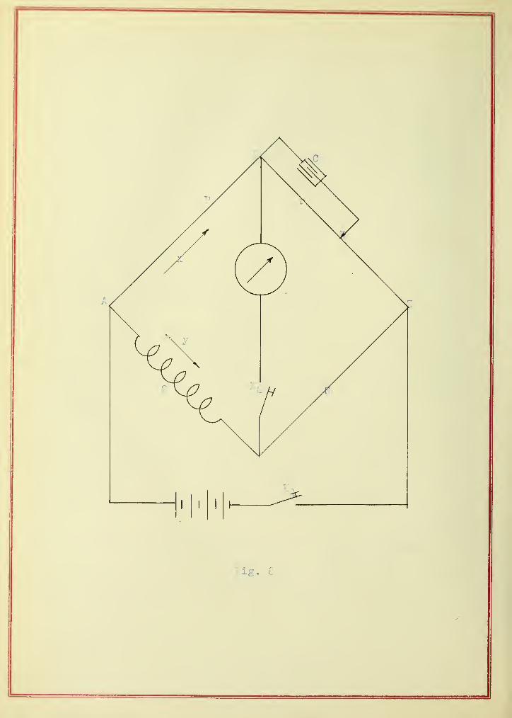
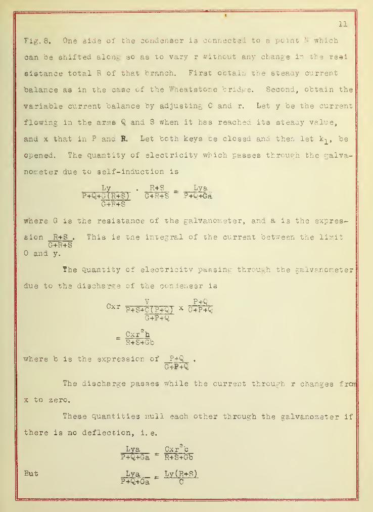
11
Fig. 8. One side of the condenser is connected to a point N which
can be shifted along so as to vary r without any change in the re*i
sistance total R of that branch. Fir3t obtain the steaay current
balance as in the case of the Wheat stone bridge^ Second, obtain the
variable current balance by adjusting C and r. Let y be the current
flowing in the arms Q and S when it has reached its steady value,
and x that in P ana R. Let both keys be closed and then let k-^, be
opened. The quantity of electricity which passes through the galva-
nometer due to self- inauct ion is
where G is the resistance of the galvanometer, and a is the expres
sion R+S . This is the integral of the current between the limitG+R+S
and y.
P+Q+G(R+ST G+R+S " ?"+Q+GaG+R+S
The quantity of electricity passing through the galvanometer
due to the discharge of the condenser is
CxrV P+Q
P+S+C(?+Q) * G+P+QG+P+Q
Cxr3h
R+S+Gb
where b is the expression of P+Q,
G+F+Q
The discharge passes while the current through r changes frar
x to zero.
These quantities null each other through the galvanometer if
there is no deflection, i. e.
a Cxr5b
?+Q+Ga ~ R+S+Gb
Eut

Fig. 9

12
and
Hence
Cxr*b _ Cxr* ( P+CQR+S+Gb " e
e - (P+Q) (G+R+S) + G(R+S)
= (R+S)(G+P+<0 + G(P+Q)
Ly(R+S) - Cxr*(P+Q)
L = Crs
x V+k
Now, x
y
y R+S
^ , by the law of divided circuits.P
L = Cr" iP * R+S
Cr3 a.R
In practiceL = Cx
slR
The experimental connection is as shown in Fig. 9.
DATA - RIMIUGTOfl ' S METHOD
Coil No. C R s b bp S r L
A 1 6. 07 500 19. 5 500 . 315 19. 815 351. 5 29. 6866
2 5. 57 500 19. 5 5C0 . 315 19. 615 365. 29. 0054
3 5. 07 5C0 19. 5 500 . 315 19. 815 385. 29. 7054
4 5. 57 500 IS. 5 50C . 315 19. 515 328. 29. 5315
5 6. 07 400 19. 5 500 . 315 19. 815 315. 29. 5305
Mean 29. 4915
B 1 7. 991 500 18. 4 539 . 34 18. 74 182. 10. 0174
a 8. 491 500 18. 4 539 . 34 18. 74 177. 9. 9697
3 8. 991 500 IS. 4 539 . 34 18. 74 172. 10. 6469
4 6. S91 400 IS. 4 539 . 34 18. 74 153. 9. 9041
5 8
.
400 18. 4 539 . 34 18. 74 158. . 9379
Mean 9. 9763

13
Coil No. C R 8 b bp S r L
C 1 6. 07 400 20. 500 . 315 20. 315 262. 21. 1611
2 5. 57 400 20. 500 . 315 «d . 515 27 4. 20. 3663
5. 07 •±00 20. 500 . 315 20. 315 288. 21. S250
4 5. 27 3 SO 20. 500 . 315 20. 315 266. 21. 3387
5 5. 87 560 30. 500 . 315 20. 315 252. 21. 1300
Mean 21. 1288
D 1 2. 09 400 20. 1 500 . 315 -20. 415 217. 5. 0552
2 2. 49 400 20. 1 500 , 515 20. 415 200. 5. 0335
3 2. 79 400 20. 1 500 . 315 20. 415 189. 5. 0851
4 3. 09 400 20. 1 500 . 315 20. 415 181. 5. 1244
5 3. 7S 400 20. 1 500 . 315 20. 415 164. 5. 2229
Mean 5. 1042
E 1 6. 07 400 20. 475 . 3 20. 3 264. 21. 5026
2 5. 57 400 20. 475 . 3 20. 3 276. 6 21. 6245
o 5. 07 400 20. 475 . 3 20. 3 290. 21. 6392
4 5. 07 500 20. 475 20. 3 524. 21 6114
5 5. 57 500 20. 475 . 3 20. 3 309. 21. 1851
Mean 21. 5126
1 11. 971 500 20. 6 526 . 331 20.931 145. 10. 4728
2 10. 971 500 20. 6 522 20.928 151. 10. 2273
3 8. 991 500 20. 6 520. . 328 20.928 168. 10. 6234
4 8. 491 500 20. 6 520. . 327 20. 9274 172. 10. 5126
5 7. 991 500 20. 6 519 . 3c7 20.927 177. 10. 4775
Mean 10. 4627


14
3. COMPARISON METHOD
The arrangement is exactly like a Wheatstone briar e. Lg is
a standard inductance of 10 millihenries. First obtain a steady
current balance. This must satisfy the condition
E . SR ~ S
Second, obtain a variable current balance, then the time constants
of the two circuits must be equal, that is,
Ll mP+Q R+S
or m F+SL2 R+F
But P QR ~ S
L2 R*~
S
The method is tedious. A single measurement of each coil
The data are g iven below.
Coil Q s b S L
A 10 14S 49. 7 474 50. 29. 8000
B 10 60 60. 460 60. 29 9.9519
C 10 S3. 5 25 497 25. 3 21. 1146
D 10 41. 1 80 514 80. 324 5. 1167
E 10 108 50 525 50. 331 31. 458
F 10 65 60 494 60. 311 10. 777 6
SECHOMMETER
It was pointed out in the previous discussion that variable
currents obtained by making or breaking the circuit is toe weak. The
comparison method is really a rude Wheat stone bridge. The resist-
ance of each arm can not be large and the galvanometer is only


15
sensitive to about one ohm resistance adjustment in the varia" le
current balance. Therefore the error is lar.-_ e. In oraer to in-
crease, the sensit ibility two methods can be applied. One is the
alternating current and vibration galva.noir.eter method; the other is
the sechommeter method. The sechommeter consists of two pieces
commutators mounted side by side upon the same shaft provided with
four brushes 3et 90 decrees apart, the shaft being rotated by an
elect ric motor .
Fig. 11 shows the arrangement of the circuit, as the commu-
tator BC. (battery con mutator) is rotated. A pulsating reversed
current is impressed at the brieve terminals AB. Since an ordinary
galvanometer does not respond to the rapid reversed impulse, the
commutator GC which rotates with the same speed as B. C. will render
the reversed current pulse unidirectional through the galvanometer,
and any lack of balance is at once indicated by a steady deflection
of the galvanometer. For lack of the facilities and time this meth-
od was not employed.
IV DISCUSSION
Comparison of Anderson's and P.irr.ington ' s Method. - A stand-
ard inductance of 10 millihenries was measured by each method. The
result is given below
Anderson's Method
R S C r L millihenry
124 13. 418 5.801 1-2 9. 984 -10. 1450
124 13. 418 3. 60-64 S. 6365-10. 1108
124 13. 418 2. 5 84-8S 9. 5 -10. 158
range of4> error


16
Rimington's Method.
c x L iyi i 1 1 i h pn tvrange cf$ error
400 17. c*7 6. 07 IS 4-195 9. 8942- 9. 996 -1. 06 to .04
400 17. 326 5. 57 203-204 9. 8965-10. 0392 -1. 04 to . 3
400 17. 525 5.07 213-214 9. 9613-11. 0055 -. 39 to . 55
From the above data, several things are noticeable.
1. In Anderson's method, the increase cf resistance decreases
the sensitivity of the galvanometer, therefore it is necessary to
make r as low as possible.
2. In both methods, the measured value is usually low. This is
due to Blight absorption of electricity by condenser during- the
transient charge and discharge.
3. Rimington's method is the closer.
Advantage s and Disadvantag e s of Andersen 1 3 Method. - The
advantages are: (l) It is the simplest of all methods. (2) It is
applicable to different detectors: galvanometer, telephone, and
vibration galvanometer. The disadvantages are: (l) It is necessary
to use small r, therefore large capacity, usually 5 microfarads and
up. However, this number of standard condenser was not available.
The condenser, no matter how small it is, must have some absorption
and a correction should be made. (2) The galvanometer was sensitive
to about 1 ohm. And since r was very small, its wire leads must
have had a slight effect on the result.
The Advantages and Disadvant ages of Rimington's Method. -
(1) It is easy to work though net so simple' as Anderson's method.
(2) The adjustment of r aces not affect the degree cf sensitiveness,
of the galvanometer. But it has the same disadvantage!in using

1 (
T r\ <m /»• a y% #% -v\ ft a i 4* ir A 1 a r\ f h a <*v o I if QV"\/"Nrv d ^ A AVi | n f q avi »• *f i if a13, r& 9 OBgPolG 1 1 iii30 ) u n© uxTouo rc.e o e r vvao on i. > 8 on bi xive to one
onm in aujusiing reoiatauo^ r.
Theoretical discussion of accuracy.- The sourcesthe o^he
ootn methods are! ^ne^iectipf) /^resis uance ana lnaucoance 01
of error in
lecLas, ana.
aosorpuion eiiecx 01 coricLer.ser. fui tney are excesuin^iy Sn.aii anu.
can oe neglected witfloui sensicic; error. ine cmei source of error
is trie ins en s 1 c 1 1 1 u y oi one gaivE.nuuie&er to une cnange 01
resistance in r.
According to Anderson's formula
ii — \j \ y r T r o
Differentiate the expression with respect to r
ql — OvV+cjcir
io of error expected = x 100L
_ (Q-rS)drOCj.ii ( C _lO A
According to Riir.ington 1 s fcrrrula
Differentiate the expression with respect to r
R
% error expecteddL _ 2drh r
(3)
In order to have minimum error, the denominator Id ooth
meoncas sncuia ce as iarf- e as j^ossioxe.
Assume r — i, one percenu error expecxeo. oi eacn coil is
thus estimated and given celow.
le
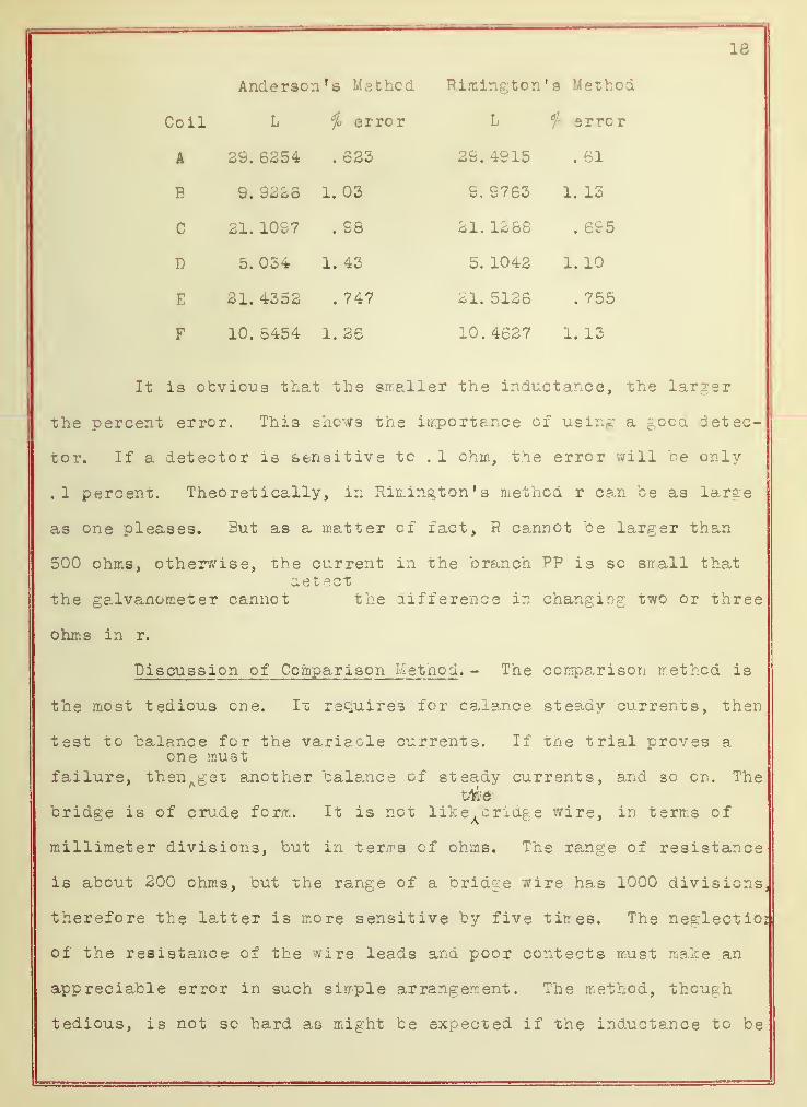
Anderson 1 a Method Rimington's Method
Coil L i i error L fc error
A 29. 6254 623 29. 4915 . 61
B 9. 9226 1. 03 S. 9763 1. 13
c 21 10S7 • S8 21. 1286 . 695
D 5. 034 1. 43 5. 1042 1. 10
E 31. 4352 • 747 21. 5126 . 755
F 10. 5454 1. 26 10. 4627 1. 13
It is obvious that the smaller the inductance, the larger
the percent error. Thi3 shows the importance of U9ing a good detec-
tor. If a detector is sensitive to . 1 ohm, the error will be only
.1 percent. Theoretically, in Rinington's method r can be as large
as one pleases. But as a matter of fact, R cannot be larger than
500 ohms, otherwise, the current in the branch PP is so small thatdet ect
the galvanometer cannot the difference in changing two or three
ohms in r.
Discuss ion of Comparison Method. - The comparison method is
the most tedious one. It requires for balance steady currents, then
test to balance for the variacle currents. If the trial proves aone must
failure, then^get another balance of steady currents, and so on. The
bridge is of crude form. It is not like^cridge wire, in terms of
millimeter divisions, but in ter/rs of ohms. The range of resistance
is about 200 ohms, but the range of a bridge wire has 1000 divisions,
therefore the latter i3 more sensitive by five tirres. The neglectioi
of the resistance of the wire leads and poor cent ect s must make an
appreciable error in such simple arrangement. The method, though
tedious, is not so hard as might be expected if the inductance to be

Fig. 12
18
measured is approximately known. It is a pood method to use as a
check of known values. It is also sensitive to one ohm.
Discussion of Some Other M ethods. - Some texts on electrici-
ty give several other methods which are not so accurate as the
above methods, but they are worthy of discussion.
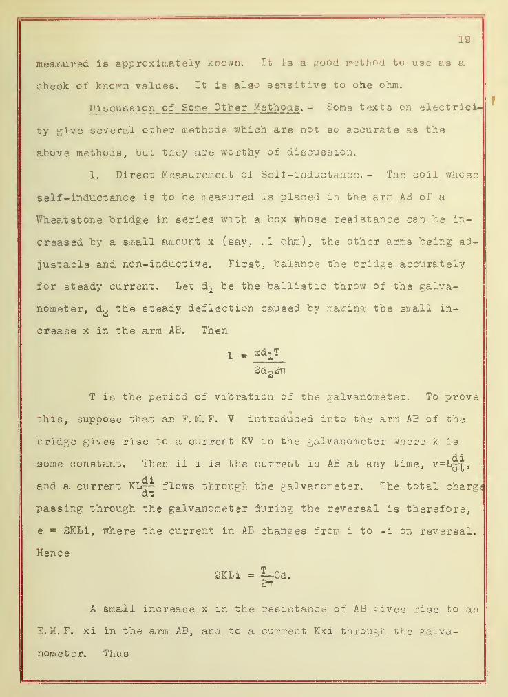
1. Direct Measurement of Self-inductance.- The coil whose
self-inductance is to be measured is placed in the arm AB of a
Wheat stone bridge in series with a box whose resistance can be in-
creased by a small amount x (say, .1 ohm), the other arms being ad-
justable and non-inductive. First, balance the bridge accurately
for steady current. Let d^ be the ballistic throw of the galva-
nometer, dg the steady deflection caused by making the small in-
crease x in the arm AE. Then
L - x^T
3d22TT
T i3 the period of vibration of the galvanometer. To prove
this, suppose that an E. H. F. V introduced into the arm AE of the
c ridge gives rise to a current KV in the galvanometer where k is
some constant. Then if i is the current in AB at any time, v=L^-,
and a current KL— flows through the galvanometer. The total chargdt
passing through the galvanometer during the reversal is therefore,
e = 2KLi, where the current in AB changes from i to -i on reversal.
Hence
2KLi = 5Lcd.2tt
A small increase x in the resistance of AB gives rise to an
E. M. F. xi in the arm AE, and to a current Kxi through the galva-
nometer. Thus


30
Kxi
L
The variables are d^ and d2 .
careful measurement. The strong objection to this method is that d^
is too small tc be observed. d^ is approximately 10 millimeters
even for large inductance, then the error of observation alone must
be liable to 2 or 3 percent.
3. Three Voltmeter* Method. A non-inductive resistance is
placed in series with the coil resistance Rg whose inductance L2 is
to be measured. An alternate current is then sent through the cir-
cuit, ana it may be measured by the ammeter. Three voltr/eter read-
ings as nearly simultaneous as possible are taken, E-,, E and E, as
shown in Fig. 13, The relation of
the three voltages is shown in the
vector diagram, Fig. 14.
* l
t«/E
H-Hg I
g
L2=
3TTfI
where f is the frequency of the
Fig. 14 alternating current. Of course, tin
frequency must be constant, and the
alternating current must be of sine
wave.
The objection to this method is that too many variables have
to be determined, therefore the error is accumulative. The accuracy
of the instrument is scarcely within lfc. This method is good for
engineering, but not for physical measurements.
How the Work May be Further Improved.- It was pointed out
that the accuracy attained is about 1$. A considerable improvement
= cd2
m xTdi .
4TTd2
T, though constant, requires


21
could have teen made, provided the time were prolonged. For in-
stance, the vibration galvanometer and sechommeter should have been
used. All the condensers used in the measurements should have teen
calibrated, since it is doubtful whether their accuracy is within
half of one percent. The plugs and seats of each resistance box
should have teen carefully cleaned, and the resistances checked with
standards.


UNIVERSITY OF ILLINOIS-URBANA


![Calculation of inductance of sparsely wound … of Inductance of Sparsely Wound Toroidal Coils ... Numerical field calculations can provide “exact” ... calculations [4], [5]. The](https://cdn.vdocuments.us/doc/165x107/5acc36e77f8b9a63398ca576/calculation-of-inductance-of-sparsely-wound-of-inductance-of-sparsely-wound.jpg)


