Download - Conflicts Color Applicability/Trim Level

Southeast Toyota Distributors, LLC Page 1 of 17
2017 LED Illumination Package (Interior and Exterior)
TOYOTA 4Runner
Part Number: 00016-00069 Accessory Code: LL1000
Conflicts Color Applicability/Trim Level
Kit Contents I tem # Quantity R eqd. Description 1 4 Puddle Lights and Harnesses 2 1 Control Module 3 1 Power Harness 4 1 Hardware bag 5 2 Foot-well Lights 6 1 Foot-well Harness 7 4 Mounting Brackets
Hardware Bag Contents
Recommended Sequence of Application I tem # Accessory 1 LED Illumination 2 Step/Running Boards 3
Additional Items Required For Installation Item # Quantity Reqd. Description
Recommended Tools Safety Tools
Special Tools
Installation ToolsRight Angle Drill Trim Removal Tool
Rivet Gun Pliers Tape Measure Drill
Torque Wrench 7/16” Drill Bit 3mm Allen wrench 11/64” Drill Bit
Fish Tape 7 & 10mm 1/4" Drive Sockets Utility Knife
Special Chemicals VPC Approved Sealant
General Applicability
Note: Power Running Boards
*Mandatory
Accessory Color
Vehicle/Trim Color
I tem # Quantity R eqd. Description 1 15 Wire Ties 2 4 Foil Tape 3 5 Foam Tape 4 14 Plastic Rivets 5 3 Red T-Taps 6 2 Black T-Tap 7 1 8 8 Mounting Bracket Bolts 9 8 Mounting Bracket Nuts
All Models without factory power running boards
Blue T-Tap
Safety Glasses
1/4" Drive Rachet

Southeast Toyota Distributors, LLC Page 2 of 17
Procedure Care must be taken when installing this accessory to ensure damage does not occur to the vehicle. The installation of this accessory should follow approved guidelines to ensure a quality installation.
These guidelines can be found in the "Accessory Installation Practices" document.
This document covers such items as: • Vehicle Protection (use of covers and blankets, cleaning chemicals, etc.).• Safety (eye protection, re-checking torque procedure, etc.).• Vehicle Disassembly/Reassembly (panel removal, part storage, etc.).• Electrical Component Disassembly/Reassembly (battery disconnection, connector removal, etc.).
Item Quantity Description Part Number 1. 4 Puddle Lights and Harnesses (a) 1 LF (4.9’) Puddle Light 00016-00064-05 (b) 1 LR (7.8’) Puddle Light 00016-00064-06
(c) 1 RF (10.8’) Puddle Light 00016-00064-07
(d) 1 RR (13.8’) Puddle Light 00016-00064-08
2. 1 Control Module 00016-00064-04 3. 1 Power Harness 00016-00064-01
4. 1 Foot-well Harness 00016-00064-02 5. 2 Foot-well Lights 00016-00064-03
6. 4 Puddle Light Mounting Brackets 00016-00069-01 7. 1 Hardware Bag
3 2 d c
a b
1
6
5
4
7

Southeast Toyota Distributors, LLC Page 3 of 17
VEHICLE PREPERATION:
1. Disconnect the negative battery cable for90 seconds before beginning installation, toavoid unintended air bag deployment. Noteand record any anti-theft radio codes priorto disconnecting.
2. Remove 7 rocker retainer clips and discardany damaged retainer clips (Figure 1).
NOTE: Retainer part # 76924-13020
3. Measure and drill locations for the rearlight pod brackets using 11/64” drillbit. These should be centeredapproximately 13” forward of the endof the pinch weld (Figure 2).
4. Measure and drill locations for thefront light pod brackets using11/64” drill bit. The bracketsshould be in line with the secondgrommet from the front (Figure 3).
5. Install all 4 mounting bracketsusing included bracket hardware.Brackets should be in-board ofpinch weld, with bolts being fedthrough the pinch weld then thebracket.
NOTE: Apply VPC approved sealant to all pinch weld holes
before mounting brackets.
Figure 1
Figure 2
Figure 3
NOTE: Insert a trim tool to use as a wedge so that rocker panel is not damaged during drilling (Figure 1b).
Figure 1b
Southeast Toyota Distributors, LLC Page 4 of 17
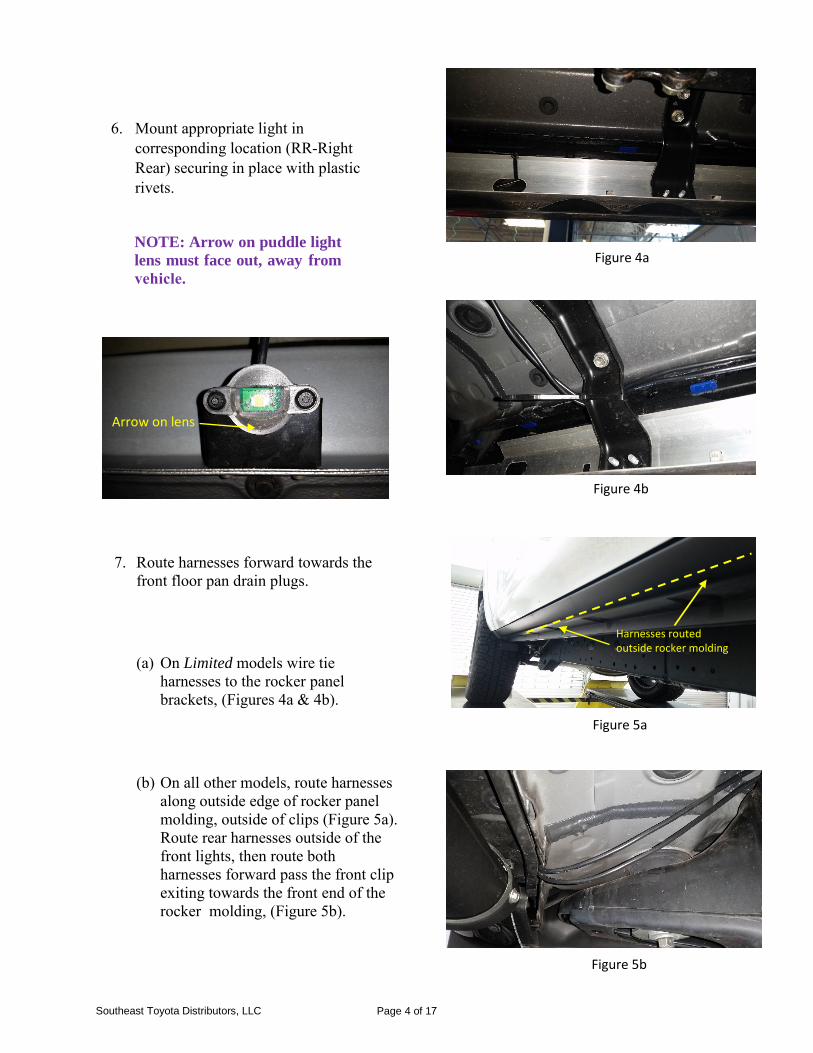
6. Mount appropriate light incorresponding location (RR-RightRear) securing in place with plasticrivets.
NOTE: Arrow on puddle light lens must face out, away from vehicle.
7. Route harnesses forward towards thefront floor pan drain plugs.
(a) On Limited models wire tie harnesses to the rocker panel brackets, (Figures 4a & 4b).
(b) On all other models, route harnesses along outside edge of rocker panel molding, outside of clips (Figure 5a). Route rear harnesses outside of the front lights, then route both harnesses forward pass the front clip exiting towards the front end of the rocker molding, (Figure 5b).
Figure 4a
Figure 4b
Figure 5b
Figure 5a
Arrow on lens
oHa
utrsniede
ssero
s croke
ur tem
do lding

Southeast Toyota Distributors, LLC Page 5 of 17
8. Remove Front Door Scuff Plate(LH)
(a) Put protective tape around the door scuff plate assembly LH (Figure 6).
(b) Using a screwdriver, detach the 4 clips, 10 claws and 2 guides to remove the door scuff plate assembly LH (Figure 6).
9. Remove Cowl Side Trim Board LH
(a) Remove the clip (Figure 7).
(b) Detach the clip and claw to remove the cowl side trim board LH.
10. Remove Front Door Scuff Plate and CowlSide Trim Board RH.
Figure 6
Figure 7

Southeast Toyota Distributors, LLC Page 6 of 17
Remove left and right front drain plugs, located directly above frame rails (Figure 8).
12. Using a sharp blade, cut an ‘X’ inthe middle of each drain plug, inorder to route the harnesses throughand into the vehicle.
13. Lift carpet to gain access to thedrain holes and route puddle lightharnesses up and into the vehicle.
14. Re-install drain plugs, with bothfront and rear harnesses threadedthrough the plugs (Figure 9).
15. Seal harnesses to drain plugs usingVPC approved sealant. Make sureto work sealant completely aroundwires for a water tight seal.
Figure 8
Figure 9
11.
Driver side Drain Plug

16. Remove No. 1 Instrument Cluster Finish Panel Garnish
(a) Put Protective tape around the No. 1 instrument cluster finish panel garnish.
(b) Grip the No. 1 instrument cluster finish panel garnish and pull it diagonally upward toward the rear to detach the 5 clips and remove the No. 1 instrument cluster finish panel garnish.
17. Remove Front No. 1 Console Box Insert.
(a) Detach the 2 clips and 2 guides toremove the front No. 1 console box insert(Figure 10).
18. Remove Front No. 2 Console Box Insert
(a) Detach the 2 clips and guide to removethe front No. 2 console box insert (Figure 11).
Figure 11
Figure 10
Page 7 of 17 Southeast Toyota Distributors, LLC

Southeast Toyota Distributors, LLC Page 8 of 17
19. Disconnect the front door openingtrim weather strip LH.
20. Remove Front Pillar Garnish LH.
(a) Using a screwdriver, detach the 2 claws to remove the front pillar garnish cover LH (Figure 12a).
Figure 12a
(b) Remove the bolt (Figure 12b).
(c) Detach the clip.
Figure 12b

Southeast Toyota Distributors, LLC Page 9 of 17
(d) Detach the 2 guides to remove the front pillar garnish LH (Figure 13).
21. Remove Lower Instrument PanelFinish Panel Sub-assembly (Figure14).
(a) Using a screwdriver, detach the 2 claws to open cover.
Figure 13
Figure 15
Figure 14
(b) Remove the 2 bolts.
(c) Detach the 13 clips and 2 guides.
(d) Disconnect each connector and hood lock control cable assembly and remove the lower instrument panel finish panel sub- assembly.

Southeast Toyota Distributors, LLC Page 10 of 17
22. Remove the Passenger Side No. 2Instrument Panel Under Cover Sub-assembly (Figure16).
(a) Detach the 3 clips and 2 guides to remove the No. 2 instrument panel under cover sub-assembly.
Figure 16 23. Drill a 7/16” hole in the injection
release point shown in Figure 17.
24. Align foot-well light withconnector in hole and flat sidefacing seats. Using a 11/64” drillbit, drill mounting holes. Attachusing included rivets.
25. Mark where driver side foot-welllight will be mounted, 1" fromthe protrusion and ½” from theback edge (Figure 18).
Figure 17
26. Drill a 7/16” hole where the foot- well light will be mounted.
27. Align light with the connectorthrough the hole and flat sidefacing the seats. Using an 11/64”drill bit, drill mounting holes.Mount light using included rivets.
Figure 18

28. Route passenger side puddle lightharnesses towards the centerconsole, under foam footboard.
29. Fish harnesses over to driver sidefoot-well.
30. Route driver side harnesses underfoam foot-board towards kickpanel.
31. Route the long side of the foot-wellpower harness from the driver sideto the passenger side, securing allpassenger side harnesses to the E- brake cable (Figure 19 & 20).
32. Drop the fused end of the powerharness from the lower corner ofthe A-pillar down towards thedriver’s kick panel, securing inexisting wire locations.
Figure 19
Figure 20
Page 11 of 17 Southeast Toyota Distributors, LLC

Southeast Toyota Distributors, LLC Page 12 of 17
33. Using a Red T-tap, connect theRed wire from the puddle lightpower harness to the Red wire inPin 13 of the FS1 connector in the A- pillar (Figure 21).
NOTE: All Connectors Pin Side View
34. Using a Red T-tap, connect theBlack wire of the puddle lightpower harness to the Green wirein Pin 15 of the FS1 connector inthe A-pillar (Figure 21).
35. Connect the Red wire from thefoot-well harness to the Red wirefrom the puddle light powerharness. Connect the White wirefrom the foot-well harness to theWhite wire from the puddle lightharness.
36. Using a Black T-tap, connect theYellow wire to the Pink wire in Pin 8of the F4 remote mirror connector(Figure 22).
37. Using a Red T-tap, connect theBlack wire to the White/Blackwire in Pin 7 of the F4 remotemirror connector (Figure 22).
Figure 21
Figure 22
FS1
F4

Southeast Toyota Distributors, LLC Page 13 of 17
38. Bundle all excess harnesses andwire tie to upper end of E-Brakecable (Figure 23).
39. Connect all harnesses to the controlmodule and mount to the factoryharnesses in the driver side kickpanel (Figure 24).
Figure 23 40. Reinstall No. 2 Instrument panelunder cover sub-assembly withattached light and connect lamp.
41. Route additional foot-wellconnector to driver side foot-welllight, connect light, and reinstalllower instrument panel finishpanel sub-assembly. Wire tieharness to panel (Figure 25).
Figure 24
Figure 25
Southeast Toyota Distributors, LLC Page 14 of 17
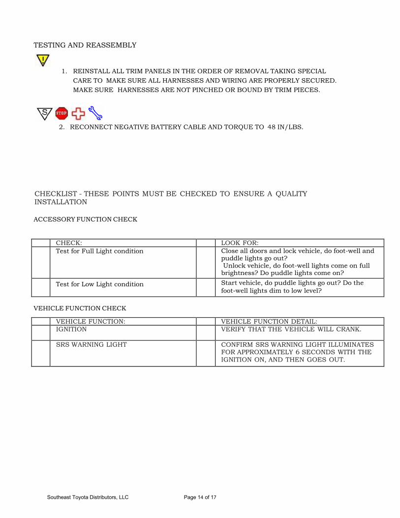
TESTING AND REASSEMBLY
1. REINSTALL ALL TRIM PANELS IN THE ORDER OF REMOVAL TAKING SPECIALCARE TO MAKE SURE ALL HARNESSES AND WIRING ARE PROPERLY SECURED.MAKE SURE HARNESSES ARE NOT PINCHED OR BOUND BY TRIM PIECES.
2. RECONNECT NEGATIVE BATTERY CABLE AND TORQUE TO 48 IN/LBS.
CHECKLIST - THESE POINTS MUST BE CHECKED TO ENSURE A QUALITY INSTALLATION
ACCESSORY FUNCTION CHECK
CHECK: LOOK FOR: Test for Full Light condition Close all doors and lock vehicle, do foot-well and
puddle lights go out? Unlock vehicle, do foot-well lights come on full brightness? Do puddle lights come on?
Test for Low Light condition Start vehicle, do puddle lights go out? Do the foot-well lights dim to low level?
VEHICLE FUNCTION CHECK
VEHICLE FUNCTION: VEHICLE FUNCTION DETAIL: IGNITION VERIFY THAT THE VEHICLE WILL CRANK.
SRS WARNING LIGHT CONFIRM SRS WARNING LIGHT ILLUMINATES FOR APPROXIMATELY 6 SECONDS WITH THE IGNITION ON, AND THEN GOES OUT.

Southeast Toyota Distributors, LLC Page 15 of 17
C10 Connect to switched
ground at LED Control Module
C11
C1 C2 C3 C4 C5
Connect to +12V at LED Control
Module
Exterior Light Pod
Exterior Light Pod
Exterior Light Pod
Exterior Light Pod
Connects to switched ground at Interior Light connector FS1 , Pin 15
C6 C7
(Fuse 1 Amp)
Connect to ground at Remote Mirror
connector F4, Pin 7
Interior Light Pod
C8 C9
Interior Light Pod
Connect to ACC at
C12
C13
Block Diagram 4Runner Lighting Package
LED Control Module
Puddle Lights can be connected to LED control module in any order
Remote Mirror connector F4, Pin 8
Connects to constant +12V at Interior Light connector FS1, Pin 13

Southeast Toyota Distributors, LLC Page 16 of 17
Connector C-1 thru C-4
Pin Wire Color Test Reference Proper Orientation 1 Black Pin 1 to Ground Exterior LEDs (-) 2 Red Pin 2 to Ground Exterior LED (+)
Connector C5
Connector C6
Pin Wire Color Test Reference Proper Operation 1 Pin 1 to Ground Approximately 0 VDC when Dome Light is ON
+12 VDC when Dome Light is OFF
Connector C7
Connector C8 & C9
Pin Wire Color Test Reference Proper Operation 1 Red Pin 1 to Ground +12 VDC 2 Black Pin 2 to Ground Approximately 0 VDC 3 White Pin 3 to Ground Approximately 0 VDC when Dome Light is ON
+12 VDC when Dome Light is OFF 4 Yellow Pin 4 to Ground Approximately 0 VDC ignition switch OFF
+12 VDC when ignition ON
2
1
Pin Wire Color Test Reference Proper Operation 1 Black Pin 1 to Ground Approximately 0 VDC 2 Red Pin 2 to Ground Approximately 0 VDC when Dome Light is ON
+12 VDC when Dome Light is OFF 3 White Pin 3 to Ground Approximately 0 VDC (when disconnected from control module) 4 Red Pin 4 to Ground Approximately 0 VDC (when disconnected from control module)
1 2
3 4
1 2
3 4
Pin Wire Color Test Reference Proper Operation
1 +12 VDC

Southeast Toyota Distributors, LLC Page 17 of 17
Connector C10
Pin Wire Color Test Reference Proper Operation 1 White Pin 1 to Ground Approximately 0 VDC when Dome Light is ON
+12 VDC when Dome Light is OFF
Connector C11
Connector C12
Pin Wire Color Test Reference Proper Operation 1 Yellow Pin 1 to Ground Approximately 0 VDC ignition switch OFF
+12 VDC when ignition ON
Connector C13
Pin Wire Color Test Reference Proper Operation
1 Red Pin 1 to Ground +12 VDC
Pin Wire Color Test Reference Proper Operation
1 Black Pin 1 to Ground Approximately 0 VDC


