
Concord Express Installation Instructions
P/N 466-1665 • REV • OCT12
Copyright © 2012 UTC Fire & Security Americas Corporation, Inc.
Interlogix is part of UTC Climate Controls & Security, a unit of United Technologies Corporation. All rights reserved.
Trademarks and
patents
Concord is trademarks of UTC Fire & Security.
Other trade names used in this document may be trademarks or registered trademarks of the
manufacturers or vendors of the respective products.
Manufacturer UTC Fire & Security Americas Corporation, Inc.
1275 Red Fox Rd., Arden Hills, MN 55112-6943, USA
Contact information www.utcfireandsecurity.com or www.interlogix.com
Customer support www.interlogix.com/customer-support
Notices
FCC Notices
FCC Part 15 Information to the User
Changes or modifications not expressly approved by UTC Fire & Security can void the user’s authority to operate the
equipment.
FCC Part 15 Class B
This equipment has been tested and found to comply with the limits for a Class B digital device, pursuant to part 15 of the
FCC Rules. These limits are designed to provide reasonable protection against interference in a residential installation.
This equipment generates, uses, and can radiate radio frequency energy and, if not installed and used in accordance with
the instructions, may cause harmful interference to radio communications. However, there is no guarantee that
interference will not occur in a particular installation.
If this equipment does cause harmful interference to radio or television reception, which can be determined by turning the
equipment off and on, the user is encouraged to try to correct the interference by one or more of the following measures:
• Reorient or relocate the receiving antenna.
• Increase the separation between the equipment and receiver.
• Connect the affected equipment and the panel receiver to separate outlets, on different branch circuits.
• Consult the dealer or an experienced radio/TV technician for help.
ACTA Part 68
This equipment complies with Part 68 of the FCC Rules. Located on this equipment is a label that contains, among o ther
information, the FCC registration number and the ringer equivalence number (REN) for this equipment. If requested, this
information must be provided to the telephone company.
FCC Part 68 Registration No. B4ZUSA-27621-AL-E REN: 0.2B
The REN is used to determine the maximum number of devices that may be connected to your telephone line. Excessive
RENs on a telephone line may result in devices not ringing in response to an incoming call. In most areas, the sum of all
device RENs should not exceed five (5.0). To be certain of the number of devices that may be connected to a line, as
determined by the total RENs, contact the local telephone company. For products approved after July 23, 2001, the REN
for this product is part of the product identifier that has the format US:AAAEQ##TXXXX. The digits represented by ## are
the REN without a decimal point (e.g., 03 is a REN of 0.3). For earlier products, the REN is separately shown on the label.

A plug and jack used to connect this equipment to the premises wiring and telephone network must comply with the
applicable FCC Part 68 rules and requirements as adopted by ACTA. A compliant telephone cord and modular plug is
provided with this product. It is designed to be connected to a compliant modular jack that is also compliant. See the
Installation Instructions for details.
Alarm dialing equipment must be able to seize the telephone line and place a call in an emergency situation. It must be
able to do this even if other equipment (telephone, answering system, computer modem, etc.) already has the telephone
line in use. To do so, alarm dialing equipment must be connected to a properly installed RJ31X jack that is electrically in
series and ahead of all other equipment attached to the same telephone line. Proper installation is depicted in the
following diagram. If you have any questions concerning these instructions, consult your local telephone company or a
qualified installer about installing an RJ31X jack and alarm dialing equipment for you.
If this equipment causes harm to the telephone network, the telephone company may temporarily disconnect your service.
If possible, you will be notified in advance. When advance notice is not practical, you will be notified as soon as possible.
You will also be advised of your right to file a complaint with the FCC.
The telephone company may make changes in its facilities, equipment, operations, or procedures that could affect the
operation of the equipment. You will be given advance notice in order to maintain uninterrupted service.
If you experience trouble with this equipment, please contact the company that installed the equipment for service and/or
repair information. The telephone company may ask you to disconnect this equipment from the network until the problem
has been corrected or you are sure that the equipment is not malfunctioning.
This equipment may not be used on coin service provided by the telephone company. Connection to party lines is subject
to state tariffs
Patent Information
This product and the use of this product may be covered by one or more of the following patents: 5,805,063, 5,872,512,
5,942,981, 4,855,713. Except expressly provided herein, the purchase of this product shall not constitute a license or
otherwise provide a right to practice a method covered by any of the identified patents. UTC Fire & Security hereby grants
the purchaser of this product a limited, non-exclusive license to practice the methods patented in the identified patents
solely with products manufactured, sold or licensed by UTC Fire & Security. This license grant does not extend to the use
of unlicensed, third party products with this product.
Canada notice The Canadian Department of Communications label identifies certified equipment. This certification means that the
equipment meets certain telecommunications network protective, operational, and safety requirements. The department
does not guarantee the equipment will operate to the user’s satisfaction.

Before installing this equipment, users should ensure that it is permissible to be connected to the facilities of the local
telecommunications company. The equipment must also be installed using an acceptable method of connection. In some
cases, the company’s inside wiring associated with a single-line individual service may be extended by means of a
certified connector assembly (telephone extension cord). The customer should be aware that compliance with the above
conditions may not prevent degradation of service in some situations.
Repairs to certified equipment should be made by an authorized Canadian maintenance facility designated by the
supplier. Any repairs or alterations made by the user to this equipment, or equipment malfunctions, may give the
telecommunications company cause to request the user to disconnect the equipment.
For your protection, make sure that the electrical ground connections of the power utility, telephone lines, and internal
metallic water pipe system, if present, are connected together
Caution: Do not attempt to make connections yourself. Contact the appropriate electrician or electric inspections
authority.
The Load Number (LN) assigned to each terminal device denotes the percentage of the total load to be connected to a
telephone loop which is used by the device, to prevent overloading. The termination on a loop may consist of any
combination of devices subject only to the requirement that the total of the LNs of all the devices does not exceed 100.
Load Number: .1 The term “IC:” before the certification/registration number only signifies that the Industry Canada
technical specifications were met. IC: 867A 787SIMON
“AVIS: - L
´
étiquette du ministère des Communications du Canada identifie le matériel homologué. Cette étiquette certifie
que le matériel est conforme a certaines normes de protection, d ´ exploitat ion et de sécurité des réseaux de
télécommunications. Le ministère n ´ assure toutefois pas que le matériel fonctionnera a la satisfaction de l ́ utilisateur.
Avant d ´ installer ce matériel, l ´ utilisateur doit s ´ assurer qu´ il est permis de le raccorder aux installations de l ́
enterprise locale de télécommunication. Le matériel doit également etre installé en suivant une méthod acceptée de
raccordement. Dans certains cas, les fils intérieurs de l´ enterprise utilisés pour un service individuel a ligne unique
peuvent etre prolongés au moyen d´ un dispositif homologué de raccordement (cordon prolongateur téléphonique
interne). L ´ abonné ne doit pas oublier qu ´ il est possible que la conformité aux conditions énoncées ci -dessus n ´
empechent pas le dégradation du service dans certaines situations. Actuellement, les enterprises de télécommunication
ne permettent pas que l ´ on raccorde leur matériel a des jacks d ´ abonné, sauf dans les cas précis prévus pas les tarrifs
particuliers de ces enterprises.
Les réparations de matériel homologué doivent etre effectuées pas un centre d ´ entretien canadien autorisé désigné par
le fournisseur. La compagne de télécommunications peut demander a l ́ utilisateur de débrancher un appareil a la suite
de réparations ou de modifications effectuées par l ´ utilisateur ou a cause de mauvais fonctionnement.
Pour sa propre protection, l ´ utilisateur doit s ́ assurer que tous les fils de mise a la terre de la source d ´ énergie
électrique, des lignes téléphoniques et des canalisations d ´´ eau métalliques, s ´ il y en a, sont raccordés ensemble.
Cette précaution est particulièrement importante dans les régions rurales.
Avertissment. - L ´ utilisateur ne doit pas tenter de faire ces raccordements lui-meme; il doit avoir recours a un service d ´
inspection des installations électriques, ou a electricien, selon le cas”.
Une note explicative sur les indices de charge (voir 1.6) et leur emploi, a l ´ intention des utilisateurs du matériel terminal,
doit etre incluse dans l ́ information qui accompagne le materiel homologué. La note pourrait etre rédigée selon le modèle
suivant:
“L ´ indice de charge (IC) assigné a chaque dispositif terminal indique, pour éviter toute surcharge, le pourcentage de la
charge totale qui peut etre raccordée a un circuit téléphonique bouclé utilisé par ce dispositif. La terminaison du circuit
bouclé peut etre constituée de n ´ import somme des indices de charge de l ´ ensemble des dispositifs ne dépasse pas
100.”
L ´ Indice de charge de cet produit est ____________.
Concord Express Installation Instructions i
Content
Notices
Chapter 1 Installation 1
Special installation requirements 2
Planning the Installation 6
Installing the System 7
Chapter 2 Programming 27
Entering programming mode 28
Programming Tier 1 Menu Items 30
Programming Tier 2 Menu Items 32
Chapter 3 Testing/Troubleshooting 71
Troubleshooting 76
Appendix A System configuration worksheets 85
Appendix B Programming mode menus and settings 103
Appendix C Software release notes and specifications 107

Concord Express Installation Instructions 1
Chapter 1 Installation
This manual provides information for planning, installing, programming, and
testing this security system. When necessary, this manual refers you to other
documentation included with compatible devices.
Planning sheets are included for you to record hardware layout and software
programming settings.
Content
Special installation requirements 2
UL Listed Systems 2
UL-Canada Listed Systems 5
Planning the Installation 6
Standard Panel 6
Touchpads 6
SnapCard™ 7
Installing the System 7
Determine the Panel Location 8
Total System Power and Wire Length Guidelines 8
Mounting the Panel 10
Identify Panel Components 11
Connecting the Panel to Earth Ground 12
Installing Optional SnapCards 13
Installing Optional Hardwire Input Modules (HIMs) 13
Connecting Detection Devices to Panel Zone Inputs#14
Connecting Sirens#17
Connecting Siren Drivers, Self-Contained Sirens, and Bells 19
Connecting Touchpads#20
Installing an RJ-31X Phone Jack (13-081)#21
Connecting the Phone Line to the Panel with a DB-8 Cord 22
Connecting the AC Power Transformer 23
Powering Up the Panel 24
Chapter 1
2 Concord Express Installation Instructions
Special installation requirements
This security system can be used as a wire warning system, an intrusion alarm
system, an emergency notification system, or any combination of the three.
Some installations may require configurations dictated by city or state codes,
insurance, or Underwriter’s Laboratories (UL). This section describes the various
component and configuration listings.
UL Listed Systems
This section describes the requirements for UL Listed systems.
Basic System
• Control Panel (60-806, 60-806-95R)
• Backup Battery, 12 VDC, 4 AH (60-681)
• SuperBus 2000 2x16 LCD Touchpad (60-746-01), SuperBus 2000 Fixed
Display Touchpad (60-820), SuperBus 2000 2x20 LCD Touchpad (60-803), or
SuperBus 2000 2x20 VFD Touchpad (60-804)
• Standard Class II 16.5 VAC, 25 VA Power Transformer; manufacturer—Tech
Electro Ind, Inc. Part No. 48A0164 (60-822) or Standard Class II 16.5 VAC,
40 VA Power Transformer; MG Electronics Model # MGT1640CC, UTC Fire &
Security # 22-156
• 15-Watt, Dual Tone Siren (13-469) or Hardwire Siren (13-046)
Household Burglary Alarm System Unit (UL 1023)
Basic system, plus:
• Hardwire Magnetic Contact (Sentrol part # 1075-N or 1038T-N) or Wireless
Learn Mode Door/Window Sensor (60-362), Wireless Learn Mode PIR Motion
Sensor (60-703-95, 60-511, or 60-639)
• IMMEDIATE TROUBLE BEEPS set to on
• UL 98 OPTIONS set to on
• RECEIVER FAILURE set to on
• EXIT DELAY set to 60 seconds or less
• QUICK EXIT set to off
• SIREN TIMEOUT set to 4 minutes or more
• SIREN VERIFY set to on
• ENTRY DELAY set to 45 seconds or less
Chapter 1
Concord Express Installation Instructions 3
• RF TX TIMEOUT set to 24 hours
• EXTENDED DELAY set to off
• TWO TRIP ERROR set to off
• ALARM VERIFY set to off
• DISABLE TROUBLE BEEPS set to off
• SYSTEM TAMPER set to on
Household Fire Warning System (UL 985)
Basic system plus:
• Hardwire Smoke Detector:
System Sensor models 2100D, 2100TD, 2100S, 2100TS, 2400, or 2400TH
learned into Sensor Group 26 Sentrol (ESL) models 429AT, 521B, or 521BXT
learned into sensor group 26
• Wireless Smoke Sensor 60-506-319.5 or 60-645-95 learned into sensor
group 26
• IMMEDIATE TROUBLE BEEPS set to on
• UL 98 OPTIONS set to on
• RECEIVER FAILURE set to on
• SIREN VERIFY set to on
• RF TX TIMEOUT set to 4 hours
• ALARM VERIFY set to off
• DISABLE TROUBLE BEEPS set to off
UL 1023 & 985 24-Hour Backup
For 24-hour backup, the total current draw for all connected devices is limited to
90 mA continuous using a 4.0 AH battery.
SIA System Requirements
Note: UL requirements take priority over SIA requirements.
SIA system requirements are the same as those described for a UL Listed Basic
System on page 1, plus:
• If multiple annunciation is required, use Hardwire Siren part no.13-046.
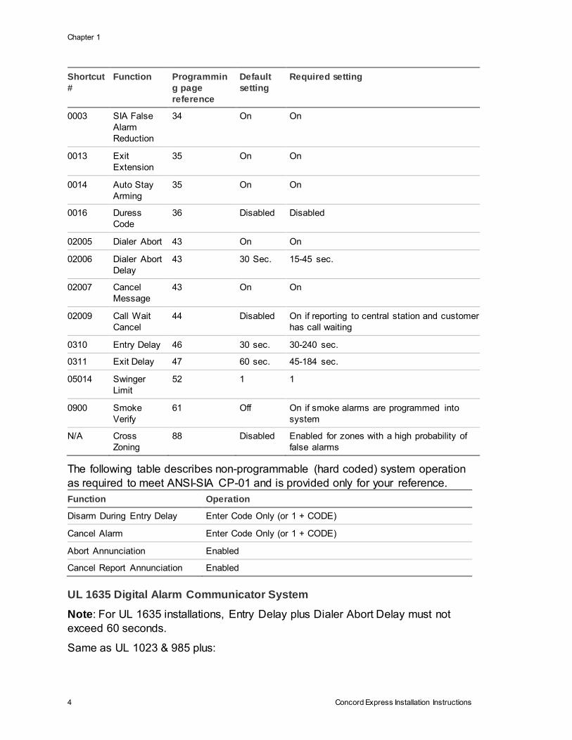
SIA Setting Requirements
The following table describes programming requirements to meet ANSI-SIA CP-
01.
Chapter 1
4 Concord Express Installation Instructions
Shortcut
#
Function Programmin
g page
reference
Default
setting
Required setting
0003 SIA False
Alarm
Reduction
34 On On
0013 Exit
Extension
35 On On
0014 Auto Stay
Arming
35 On On
0016 Duress
Code
36 Disabled Disabled
02005 Dialer Abort 43 On On
02006 Dialer Abort
Delay
43 30 Sec. 15-45 sec.
02007 Cancel
Message
43 On On
02009 Call Wait
Cancel
44 Disabled On if reporting to central station and customer
has call waiting
0310 Entry Delay 46 30 sec. 30-240 sec.
0311 Exit Delay 47 60 sec. 45-184 sec.
05014 Swinger
Limit
52 1 1
0900 Smoke
Verify
61 Off On if smoke alarms are programmed into
system
N/A Cross
Zoning
88 Disabled Enabled for zones with a high probability of
false alarms
The following table describes non-programmable (hard coded) system operation
as required to meet ANSI-SIA CP-01 and is provided only for your reference.
Function Operation
Disarm During Entry Delay Enter Code Only (or 1 + CODE)
Cancel Alarm Enter Code Only (or 1 + CODE)
Abort Annunciation Enabled
Cancel Report Annunciation Enabled
UL 1635 Digital Alarm Communicator System
Note: For UL 1635 installations, Entry Delay plus Dialer Abort Delay must not
exceed 60 seconds.
Same as UL 1023 & 985 plus:
Chapter 1
Concord Express Installation Instructions 5
• AC FAILURE set to on
• PHONE NUMBER must be programmed
• HIGH LEVEL REPORTS set to on.
• LOW LEVEL REPORTS set to on
• PHONE TEST set to on
• AUTO PHONE TEST set to on
• PHONE TEST FREQ. set to 1
• NEXT PHONE TEST set to 1
• LOW CPU BATTERY set to on
• COMM FAILURE set to on
• RF TX TIMEOUT set to 4 hours
Central Station Reporting
The panel has been tested with the following central station receivers using SIA
and Contact ID reporting formats:
• CS-5000 Central Station Receiver
• Sur-Gard Central Station Receiver with models SG-DRL2A and SG-CPM2
UL-Canada Listed Systems
This section describes the requirements for ULC (UL Canada) Listed systems.
• CSA Certified Accessories
The UL-Canada Basic System is nearly the same as the “UL Basic System”
described previously, the only difference being that you must use the ITI 60-
679-CN Class II transformer (Basler part number BE 116250-AAA) to power
the panel.
• Residential Burglary Alarm System Unit
(CAN/ULC-S309)
Same as “UL Basic System and Household Burglary Alarm System Unit (UL
1023)” described previously and siren timeout must be set to 5 minutes or
more.
Residential Fire Warning System Control Unit (CAN/ULC-S545-M89)
Same as “UL Basic System and Household Fire Warning System (UL 985)”
described previously.
Note: For 24-hour backup, external power drain is limited to 90 mA continuous
using a 4.0AH battery.
California State Fire Marshall Listed Systems
Same as Household Fire Warning System (UL 985), plus:
Chapter 1
6 Concord Express Installation Instructions
• SMOKE VERIFY must be set to off
Planning the Installation
This section describes the system capabilities to help you get familiar with the
system. To help you prepare for system installation, Appendix A provides
planning sheets with tables that let you record the hardware and programming
configuration of the system.
Standard Panel
The following describes the basic panel (out-of-box) hardware capabilities.
• Power: Input for an AC step-down, plug-in style transformer.
• Auxiliary Power Output: Output that supplies up to 750 mA (90 mA for UL
Listed systems) at 12 VDC for bus devices and hardwired detectors, such as
touchpads and motion detectors.
• Bus A and B: Input and output that provide communication between bus
devices and the panel.
• 2 Onboard Outputs: One 12-volt and one open-collector output that can be
set up to activate other signalling devices, based on system events.
• 6 Supervised Hardwire Zones: Factory programmed inputs for various
hardwired detectors (see “Accessory Modules Menu” on page 60 for a list of
factory programmed settings). Zone 6 can be set up in programming to
accept 2-wire smoke detectors.
• Built-In Radio Receiver: Allows use of UTC Fire & Security 319.5 MHz.
crystal and/or SAW Learn Mode wireless sensors and touchpads.
• Phone Line Connection: Allows the panel to communicate with central
monitoring stations and pagers.
Touchpads
The following describes the different touchpads that can be used for system
programming and operation.
• SuperBus 2000 2x16 LCD Alphanumeric Touchpad: Provides complete
system programming and operation control. Displays system messages, and
indicates system status.

Chapter 1
Concord Express Installation Instructions 7
• SuperBus 2000 2x20 LCD/VFD Alphanumeric Touchpads: Provide
complete system programming and operation control, display system
messages and indicate system status.
• SuperBus 2000 Fixed Display LCD Touchpad: Provides operation control
and user programming access (not installer or dealer programming). Displays
system messages and indicates system status.
SnapCard™
The following SnapCards expand the system as described:
• 8Z Input SnapCard: Provides eight additional hardwire zone inputs, of which
two are dedicated for 2-wire smoke detectors.
• 4 Output SnapCard: Provides four form C relay outputs that can be set up to
activate other signalling devices, based on system events.
• 4Z Input/2 Output Combo SnapCard: Provides three standard hardwire
zone inputs, one 2-wire smoke detector loop input, and two outputs that can
be set up to activate other signalling devices that are based on system
events.
Installing the System
This section describes how to install the system control panel. Before starting the
installation, plan your system layout and programming using the worksheets
provided in Appendix A.
Installing the system consists of the following steps:
• Determining the Panel Location
• Identifying Total System Power and Wire Length Guidelines
• Mounting the Panel
• Identifying Panel Main Components
• Installing Optional SnapCards
• Installing Optional HIMs
• Connecting Detection Devices to Panel Zone Inputs
• Connecting Sirens
• Connecting Touchpads
• Installing an RJ-31X Phone Jack
• Connecting the Phone Line to the Panel with a DB-8 Cord
• Connecting the AC Power Transformer
• Powering Up the Panel

Chapter 1
8 Concord Express Installation Instructions
Determine the Panel Location
Before permanently mounting the panel, determine the location using the
following guidelines:
• To help reduce wire run lengths and labor, centrally locate the panel with
relation to detection devices whenever possible.
• Avoid running wires parallel with electrical wiring or fixtures, such as
fluorescent lighting, to prevent wire runs from picking up electrical noise.
• Mount the panel at a comfortable working height (about 45 to 55 inches from
the floor to the bottom of the panel, as shown in Figure 1 below).
• Leave space to the left and right of the panel for wiring, phone jack, and
optional modules.
• For installations that include wireless sensors, allow at least 10 inches above
the panel cabinet for the antenna.
• Allow at least 24 inches in front of the panel for opening the panel door.
Figure 1: Determining panel location
Total System Power and Wire Length Guidelines
Note: A) Class 2, Class 3, and power-limited fire alarm circuits must be installed
using FPL, FPLR, FPLP, or substitute cable permitted by the National Electrical
Code ANSI/NFPA 70. Wire that extends beyond the cable jacket must be
separated from all other conductors by a minimum of 1/4-inch or by a
nonconductive barrier.
OR
Chapter 1
Concord Express Installation Instructions 9
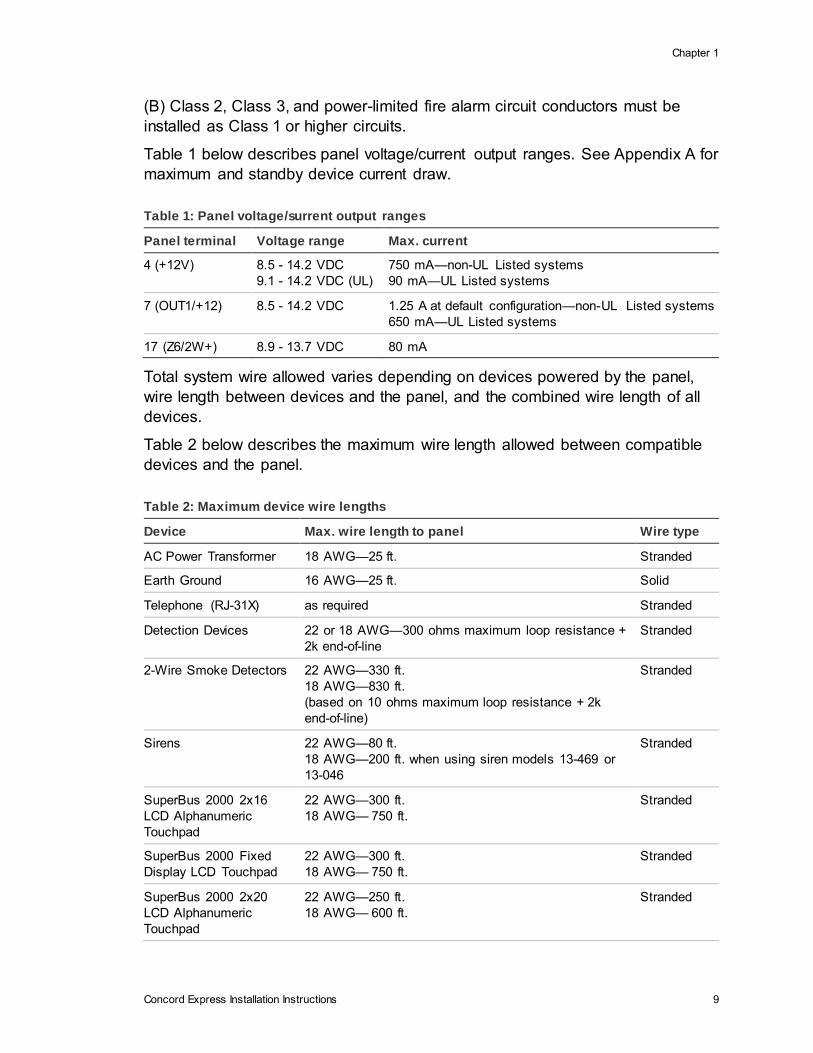
(B) Class 2, Class 3, and power-limited fire alarm circuit conductors must be
installed as Class 1 or higher circuits.
Table 1 below describes panel voltage/current output ranges. See Appendix A for
maximum and standby device current draw.
Table 1: Panel voltage/surrent output ranges
Panel terminal Voltage range Max. current
4 (+12V) 8.5 - 14.2 VDC
9.1 - 14.2 VDC (UL)
750 mA—non-UL Listed systems
90 mA—UL Listed systems
7 (OUT1/+12) 8.5 - 14.2 VDC 1.25 A at default configuration—non-UL Listed systems
650 mA—UL Listed systems
17 (Z6/2W+) 8.9 - 13.7 VDC 80 mA
Total system wire allowed varies depending on devices powered by the panel,
wire length between devices and the panel, and the combined wire length of all
devices.
Table 2 below describes the maximum wire length allowed between compatible
devices and the panel.
Table 2: Maximum device wire lengths
Device Max. wire length to panel Wire type
AC Power Transformer 18 AWG—25 ft. Stranded
Earth Ground 16 AWG—25 ft. Solid
Telephone (RJ-31X) as required Stranded
Detection Devices 22 or 18 AWG—300 ohms maximum loop resistance +
2k end-of-line
Stranded
2-Wire Smoke Detectors 22 AWG—330 ft.
18 AWG—830 ft.
(based on 10 ohms maximum loop resistance + 2k
end-of-line)
Stranded
Sirens 22 AWG—80 ft.
18 AWG—200 ft. when using siren models 13-469 or
13-046
Stranded
SuperBus 2000 2x16
LCD Alphanumeric
Touchpad
22 AWG—300 ft.
18 AWG— 750 ft.
Stranded
SuperBus 2000 Fixed
Display LCD Touchpad
22 AWG—300 ft.
18 AWG— 750 ft.
Stranded
SuperBus 2000 2x20
LCD Alphanumeric
Touchpad
22 AWG—250 ft.
18 AWG— 600 ft.
Stranded

Chapter 1
10 Concord Express Installation Instructions
Device Max. wire length to panel Wire type
SuperBus 2000 2x20
VFD Alphanumeric
Touchpad
22 AWG—250 ft.
18 AWG— 600 ft.
Stranded
SuperBus 2000 Hardwire
Input Module
22 AWG—1,800 ft.
18 AWG— 4,500 ft.
Stranded
Mounting the Panel
Use the following procedure to mount the panel to the wall or wall studs.
Caution: Make sure you are free of static electricity whenever you work on the
panel with the cover open. To discharge any static, first touch the metal panel
chassis, then stay in contact with the chassis when touching the circuit board.
Using an approved grounding strap is recommended.
To mount the panel cabinet and circuit board:
1. Open the panel door and slide it up to remove it from the cabinet. Set the
door aside.
2. Remove the knockout to provide access for system wiring (see Figure 2
below).
3. Feed all device wires through the knockout and place the panel in position
against the wall.
4. Level the panel and mark the top and bottom mounting holes (see Figure 2
below).
Figure 2: Mounting holes

Chapter 1
Concord Express Installation Instructions 11
5. Install anchors where studs are not present.
6. Partially insert screws into the two top mounting hole locations, then hang the
panel on the two screws.
7. Recheck for levelness, insert the two lower screws, and tighten all four
mounting screws.
8. Install the antenna housing (included with the panel) by pushing it down into
the top left hole of the cabinet until it snaps into place (see Figure 3 below).
9. Install the circuit board into the cabinet, inserting the loop antenna loop up
into the antenna housing (see Figure 3 below), then secure the circuit board
with the four mounting screws (included).
Figure 3: Installing the antenna housing and the circuit board
Identify Panel Components
Before installing devices and making wiring connections, familiarize yourself with
the main components of the panel. Figure 4 on page 12 shows the main
component locations on the circuit board.
Chapter 1
12 Concord Express Installation Instructions
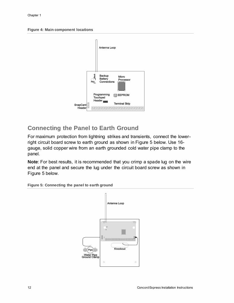
Figure 4: Main component locations
Connecting the Panel to Earth Ground
For maximum protection from lightning strikes and transients, connect the lower-
right circuit board screw to earth ground as shown in Figure 5 below. Use 16-
gauge, solid copper wire from an earth grounded cold water pipe clamp to the
panel.
Note: For best results, it is recommended that you crimp a spade lug on the wire
end at the panel and secure the lug under the circuit board screw as shown in
Figure 5 below.
Figure 5: Connecting the panel to earth ground
Chapter 1
Concord Express Installation Instructions 13
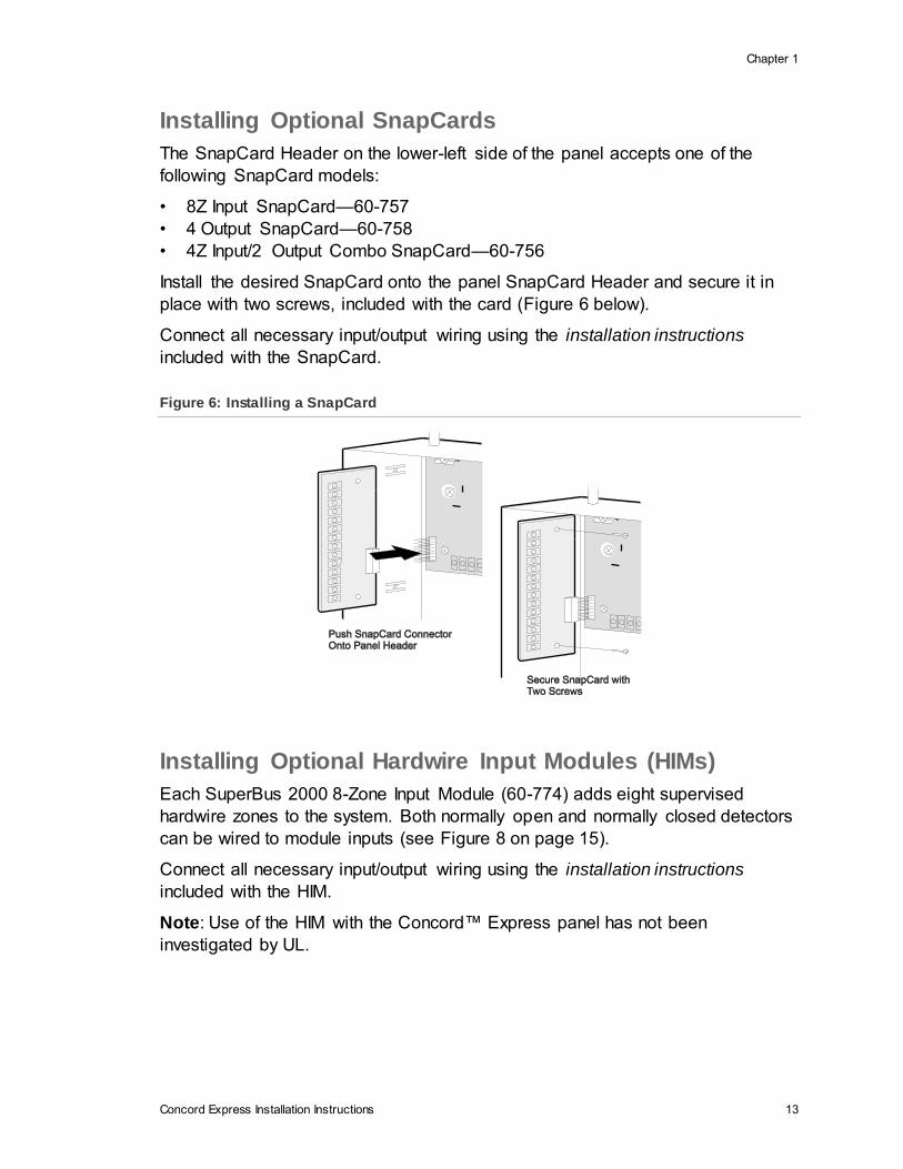
Installing Optional SnapCards
The SnapCard Header on the lower-left side of the panel accepts one of the
following SnapCard models:
• 8Z Input SnapCard—60-757
• 4 Output SnapCard—60-758
• 4Z Input/2 Output Combo SnapCard—60-756
Install the desired SnapCard onto the panel SnapCard Header and secure it in
place with two screws, included with the card (Figure 6 below).
Connect all necessary input/output wiring using the installation instructions
included with the SnapCard.
Figure 6: Installing a SnapCard
Installing Optional Hardwire Input Modules (HIMs)
Each SuperBus 2000 8-Zone Input Module (60-774) adds eight supervised
hardwire zones to the system. Both normally open and normally closed detectors
can be wired to module inputs (see Figure 8 on page 15).
Connect all necessary input/output wiring using the installation instructions
included with the HIM.
Note: Use of the HIM with the Concord™ Express panel has not been
investigated by UL.
Chapter 1
14 Concord Express Installation Instructions
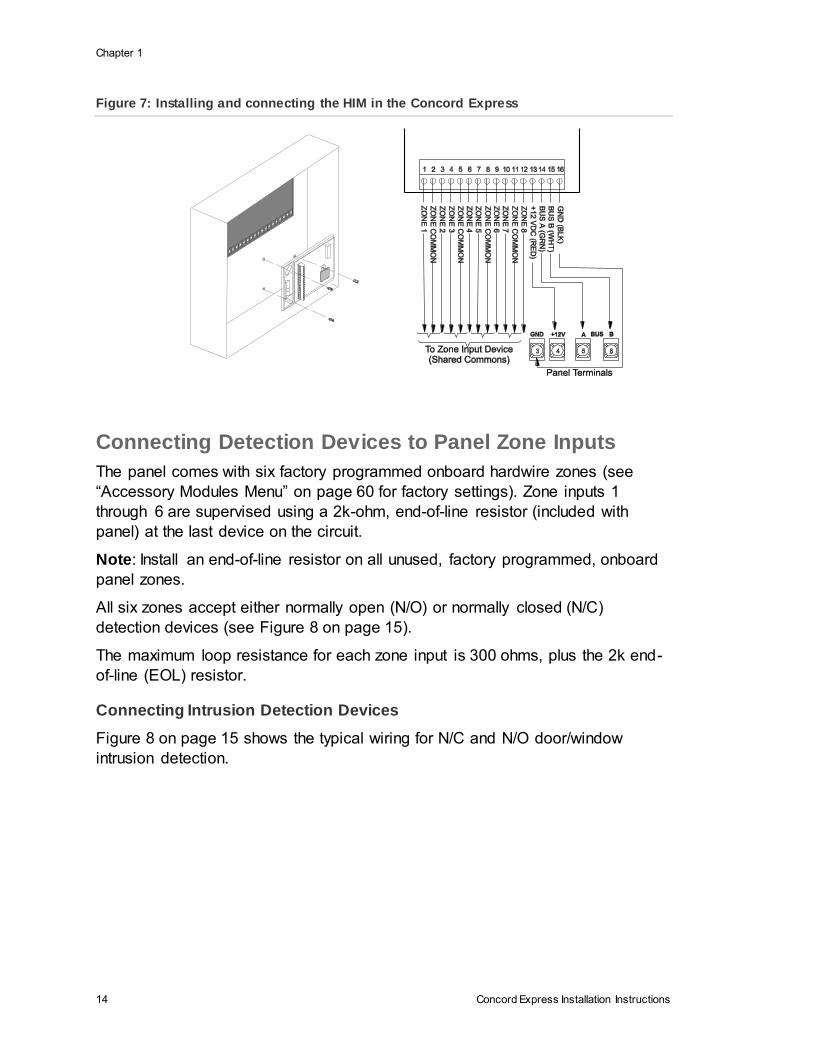
Figure 7: Installing and connecting the HIM in the Concord Express
Connecting Detection Devices to Panel Zone Inputs
The panel comes with six factory programmed onboard hardwire zones (see
“Accessory Modules Menu” on page 60 for factory settings). Zone inputs 1
through 6 are supervised using a 2k-ohm, end-of-line resistor (included with
panel) at the last device on the circuit.
Note: Install an end-of-line resistor on all unused, factory programmed, onboard
panel zones.
All six zones accept either normally open (N/O) or normally closed (N/C)
detection devices (see Figure 8 on page 15).
The maximum loop resistance for each zone input is 300 ohms, plus the 2k end-
of-line (EOL) resistor.
Connecting Intrusion Detection Devices
Figure 8 on page 15 shows the typical wiring for N/C and N/O door/window
intrusion detection.
Chapter 1
Concord Express Installation Instructions 15
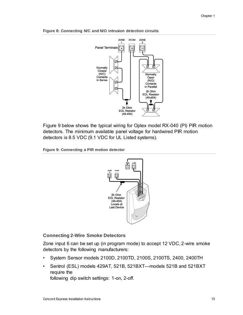
Figure 8: Connecting N/C and N/O intrusion detection circuits
Figure 9 below shows the typical wiring for Optex model RX-040 (PI) PIR motion
detectors. The minimum available panel voltage for hardwired PIR motion
detectors is 8.5 VDC (9.1 VDC for UL Listed systems).
Figure 9: Connecting a PIR motion detector
Connecting 2-Wire Smoke Detectors
Zone input 6 can be set up (in program mode) to accept 12 VDC, 2-wire smoke
detectors by the following manufacturers:
• System Sensor models 2100D, 2100TD, 2100S, 2100TS, 2400, 2400TH
• Sentrol (ESL) models 429AT, 521B, 521BXT—models 521B and 521BXT
require the
following dip switch settings: 1-on, 2-off.
Chapter 1
16 Concord Express Installation Instructions
Note: When using 2-wire smoke detectors on Zone 6, the Two-Wire Smoke
setting (in program mode) must be turned on before entering the LEARN
SENSORS menu. See ONBOARD OPTIONS—INPUTS in the section “Entering
programming mode” on page 28 for complete details.
WARNING: Use only 2-wire smoke detector models described above. Alarm
signals from other detectors may not be processed correctly if the panel has lost
AC power and is operating only from the backup battery.
When set up for 2-wire smoke detectors, zone 6 can handle up to 10 smoke
detectors with 120 µA maximum idle current per detector. Maximum total loop
current allowed in an alarm condition is 80 mA. The maximum loop resistance for
2-wire smoke detectors connected to zone input 6 is 10 ohms, plus the 2k end-
of-line resistor.
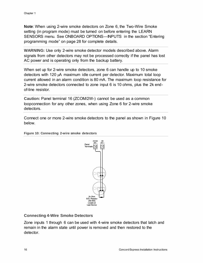
Caution: Panel terminal 16 (ZCOM/2W-) cannot be used as a common
loopconnection for any other zones, when using Zone 6 for 2-wire smoke
detectors.
Connect one or more 2-wire smoke detectors to the panel as shown in Figure 10
below.
Figure 10: Connecting 2-wire smoke detectors
Connecting 4-Wire Smoke Detectors
Zone inputs 1 through 6 can be used with 4-wire smoke detectors that latch and
remain in the alarm state until power is removed and then restored to the
detector.

Chapter 1
Concord Express Installation Instructions 17
The panel provides this power interruption from panel terminal 8 (OUT2/OC)
provided that the output configuration number is set (in program mode) to 01500.
For more information on output configuration numbers, see the section
“Programming the Panel” and the tables in Appendix A. Use only 4-wire smoke
detectors that operate on 8.5 to 14.2 VDC.
Note: The Two-Wire Smoke setting (in program mode) must be off when
connecting
4-wire smoke detectors to zone 6. For UL Listed systems, 4-wire smoke
detectors cannot be connected to onboard panel zone inputs.
Connect up to five Sentrol (ESL) model 449AT (ITI part no. 13-360) smoke
detectors to panel power input as shown in Figure 11 below.
Figure 11: Connecting 4-wire smoke detectors
Connecting Sirens
Note: Install all sirens/speakers indoors, in a concealed location.
Two onboard programmable outputs allow for siren connections when using the
default setting of each output. For more information on output configuration
numbers, see the section “Programming the Panel” and the tables in Appendix A.
The following describes siren connections using the default settings of each
onboard output.
Chapter 1
18 Concord Express Installation Instructions
Note: If the backup battery is not connected, or if the configuration of panel
terminal 7 is programmed to anything other than the default (00410), then the
combined currents of terminal 7 (OUT 1/+12) and terminal 4 (+12V) must not
exceed 750 mA.
15-Watt, Dual Tone Siren (13-469)
Panel terminal 7 (OUT1/+12V) is a +12V programmable output. At the default
configuration setting (00410), this output can provide up to 1.25 A during an
alarm (650 mA for UL Listed systems) if the backup battery is connected.
The default configuration setting (00410) activates the output during any audible
alarm, allowing for a siren connection without changing the output configuration
number.
Note: For UL Listed systems, Siren Verify must be on.
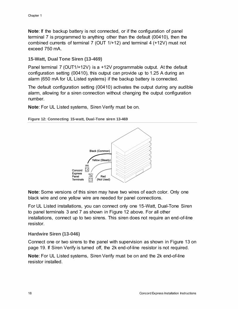
Figure 12: Connecting 15-watt, Dual-Tone siren 13-469
Note: Some versions of this siren may have two wires of each color. Only one
black wire and one yellow wire are needed for panel connections.
For UL Listed installations, you can connect only one 15-Watt, Dual-Tone Siren
to panel terminals 3 and 7 as shown in Figure 12 above. For all other
installations, connect up to two sirens. This siren does not require an end-of-line
resistor.
Hardwire Siren (13-046)
Connect one or two sirens to the panel with supervision as shown in Figure 13 on
page 19. If Siren Verify is turned off, the 2k end-of-line resistor is not required.
Note: For UL Listed systems, Siren Verify must be on and the 2k end-of-line
resistor installed.
Chapter 1
Concord Express Installation Instructions 19
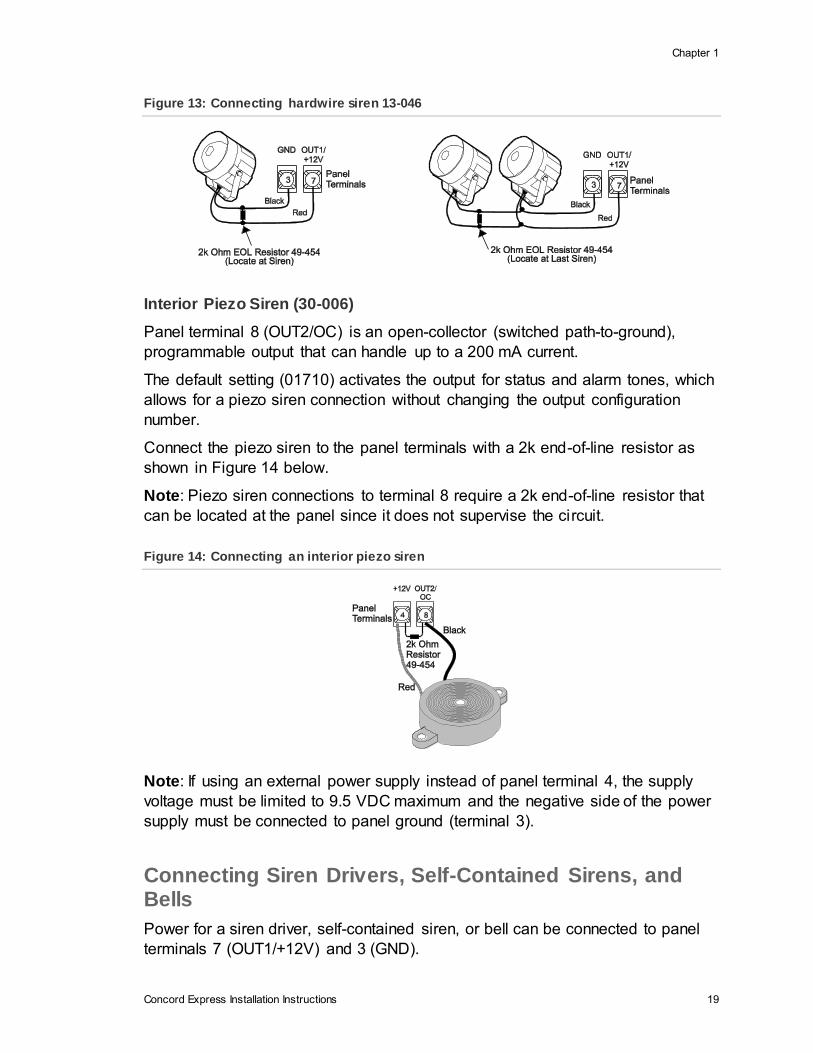
Figure 13: Connecting hardwire siren 13-046
Interior Piezo Siren (30-006)
Panel terminal 8 (OUT2/OC) is an open-collector (switched path-to-ground),
programmable output that can handle up to a 200 mA current.
The default setting (01710) activates the output for status and alarm tones, which
allows for a piezo siren connection without changing the output configuration
number.
Connect the piezo siren to the panel terminals with a 2k end-of-line resistor as
shown in Figure 14 below.
Note: Piezo siren connections to terminal 8 require a 2k end-of-line resistor that
can be located at the panel since it does not supervise the circuit.
Figure 14: Connecting an interior piezo siren
Note: If using an external power supply instead of panel terminal 4, the supply
voltage must be limited to 9.5 VDC maximum and the negative side of the power
supply must be connected to panel ground (terminal 3).
Connecting Siren Drivers, Self-Contained Sirens, and Bells
Power for a siren driver, self-contained siren, or bell can be connected to panel
terminals 7 (OUT1/+12V) and 3 (GND).
Chapter 1
20 Concord Express Installation Instructions
Panel terminal 7 (OUT1/+12V) is a +12-volt programmable output. At the default
configuration setting (00410), this output can provide up to 1.25 A during an
alarm (650 mA for
UL Listed systems) if the backup battery is connected.
Note: If the backup battery is not connected, or if the configuration of panel
terminal 7 is programmed to anything other than the default (00410), then the
combined currents of terminal 7 (OUT 1/+12) and terminal 4 (+12V) must not
exceed 750 mA.
The default configuration setting (00410) activates the output during any audible
alarm.
The following siren drivers, self-contained sirens, and bells have been tested and
found compatible for use with the panel:
• Moose Models MPI-11 (use only 8-ohm speaker loads), MP-47, MP-47B
• Altronix Model ALSD2 (4- or 8-ohm speaker loads)
• ATW Models DT-24, DS508 (both self-contained)
• Wheelock MB-G6-12 Six-inch, 12V Bell
Refer to the manufacturer’s documentation for installation details.
Connecting Touchpads
• SuperBus 2000 2x16 LCD Alphanumeric Touchpad (60-746-01)
• SuperBus 2000 2x20 LCD Alphanumeric Touchpads (60-803, 60-809)
• SuperBus 2000 2x20 VFD Alphanumeric Touchpad (60-804, 60-810)
• SuperBus 2000 Fixed Display LCD Touchpad (60-820)
Alphanumeric touchpads can be used for installer programming, system
operation, and user programming. Fixed display touchpads can be used for
system operation and user programming but not for installer programming.
Note: Be sure to have an alphanumeric (programming) touchpad on hand for on-
site programming in installations that do not include one as part of the final
system configuration. This programming touchpad can be connected to the
Programming Touchpad Header (see Figure 15 on page 21) using a
Programming Touchpad Cable (part no. 60-791).
Connect 2x16 and fixed display LCD touchpads to the panel power output and
bus terminals as shown in Figure 15 on page 21.
The 2x20 LCD/VFD touchpads include a supervised hardwire input for
connection to a hardwire detection device (see Figure 15 on page 21 for an
example of a normally closed connection).
Chapter 1
Concord Express Installation Instructions 21
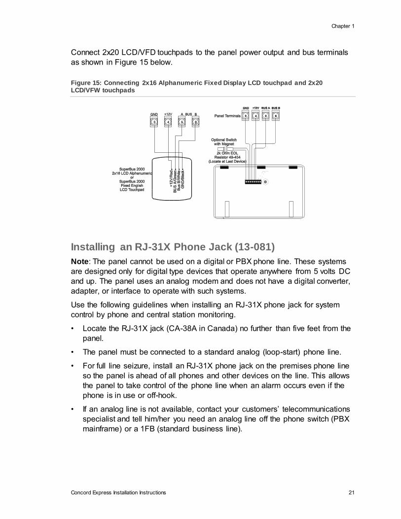
Connect 2x20 LCD/VFD touchpads to the panel power output and bus terminals
as shown in Figure 15 below.
Figure 15: Connecting 2x16 Alphanumeric Fixed Display LCD touchpad and 2x20 LCD/VFW touchpads
Installing an RJ-31X Phone Jack (13-081)
Note: The panel cannot be used on a digital or PBX phone line. These systems
are designed only for digital type devices that operate anywhere from 5 volts DC
and up. The panel uses an analog modem and does not have a digital converter,
adapter, or interface to operate with such systems.
Use the following guidelines when installing an RJ-31X phone jack for system
control by phone and central station monitoring.
• Locate the RJ-31X jack (CA-38A in Canada) no further than five feet from the
panel.
• The panel must be connected to a standard analog (loop-start) phone line.
• For full line seizure, install an RJ-31X phone jack on the premises phone line
so the panel is ahead of all phones and other devices on the line. This allows
the panel to take control of the phone line when an alarm occurs even if the
phone is in use or off-hook.
• If an analog line is not available, contact your customers’ telecommunications
specialist and tell him/her you need an analog line off the phone switch (PBX
mainframe) or a 1FB (standard business line).
Chapter 1
22 Concord Express Installation Instructions
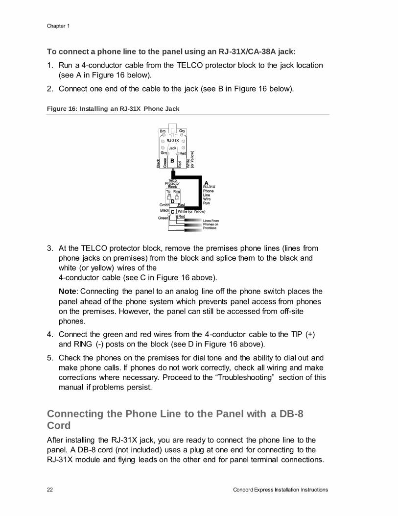
To connect a phone line to the panel using an RJ-31X/CA-38A jack:
1. Run a 4-conductor cable from the TELCO protector block to the jack location
(see A in Figure 16 below).
2. Connect one end of the cable to the jack (see B in Figure 16 below).
Figure 16: Installing an RJ-31X Phone Jack
3. At the TELCO protector block, remove the premises phone lines (lines from
phone jacks on premises) from the block and splice them to the black and
white (or yellow) wires of the
4-conductor cable (see C in Figure 16 above).
Note: Connecting the panel to an analog line off the phone switch places the
panel ahead of the phone system which prevents panel access from phones
on the premises. However, the panel can still be accessed from off-site
phones.
4. Connect the green and red wires from the 4-conductor cable to the TIP (+)
and RING (-) posts on the block (see D in Figure 16 above).
5. Check the phones on the premises for dial tone and the ability to dial out and
make phone calls. If phones do not work correctly, check all wiring and make
corrections where necessary. Proceed to the “Troubleshooting” section of this
manual if problems persist.
Connecting the Phone Line to the Panel with a DB-8 Cord
After installing the RJ-31X jack, you are ready to connect the phone line to the
panel. A DB-8 cord (not included) uses a plug at one end for connecting to the
RJ-31X module and flying leads on the other end for panel terminal connections.
Chapter 1
Concord Express Installation Instructions 23
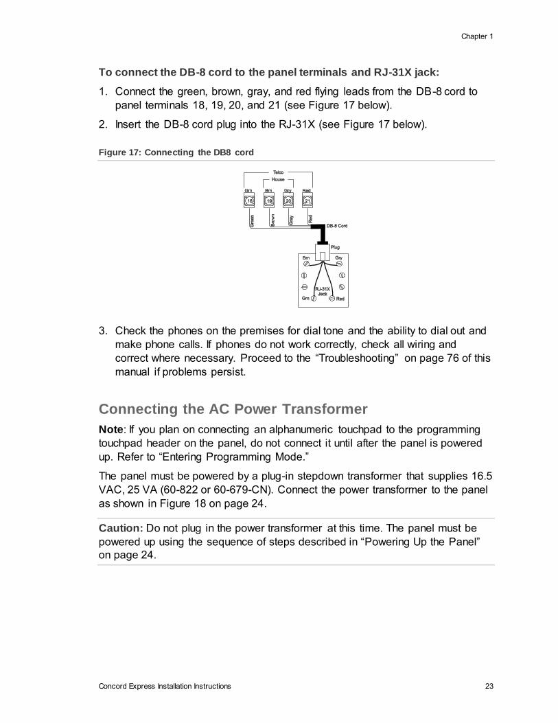
To connect the DB-8 cord to the panel terminals and RJ-31X jack:
1. Connect the green, brown, gray, and red flying leads from the DB-8 cord to
panel terminals 18, 19, 20, and 21 (see Figure 17 below).
2. Insert the DB-8 cord plug into the RJ-31X (see Figure 17 below).
Figure 17: Connecting the DB8 cord
3. Check the phones on the premises for dial tone and the ability to dial out and
make phone calls. If phones do not work correctly, check all wiring and
correct where necessary. Proceed to the “Troubleshooting” on page 76 of this
manual if problems persist.
Connecting the AC Power Transformer
Note: If you plan on connecting an alphanumeric touchpad to the programming
touchpad header on the panel, do not connect it until after the panel is powered
up. Refer to “Entering Programming Mode.”
The panel must be powered by a plug-in stepdown transformer that supplies 16.5
VAC, 25 VA (60-822 or 60-679-CN). Connect the power transformer to the panel
as shown in Figure 18 on page 24.
Caution: Do not plug in the power transformer at this time. The panel must be
powered up using the sequence of steps described in “Powering Up the Panel”
on page 24.

Chapter 1
24 Concord Express Installation Instructions
Figure 18: Connecting the power transformer
Powering Up the Panel
Note: Without AC power, shutdown will occur if battery voltage falls below 10.2
VDC.
After installing SnapCards and wiring all devices to the panel, you are ready to
apply AC and backup battery power to the panel.
To power up the panel:
1. Connect the red and black battery leads (included with panel) to the lugs
located in the upper-left area of the panel circuit board (see Figure 19 below).
Figure 19: Connecting the backup battery
2. Connect the battery leads to the battery terminals as shown.
3. Plug the transformer into an outlet that is not controlled by a switch or ground
fault circuit interrupt (GFCI).
Chapter 1
Concord Express Installation Instructions 25
Alphanumeric touchpads display ************, SCANNING BUS DEVICES,
then a date and time display. Fixed display touchpads briefly show all text, no
text, BUS SCAN, then a time display.
4. To permanently mount the transformer, unplug it and remove the existing
screw securing the AC outlet cover.
5. Hold the outlet cover in place and plug the transformer into the lower
receptacle.
6. Use the screw supplied with the transformer to secure the transformer to the
outlet cover.
WARNING: Use extreme caustion when securing the transformer to a metal
outlet cover. You could receive a serious shock if a metal outlet cover drops onto
the prongs of the plug while you are securing the transformer and cover to the
outlet box.
Note: If touchpads don’t display anything, immediately unplug the transformer
and disconnect the backup battery. Refer to the “Troubleshooting” on page 76.

Concord Express Installation Instructions 27
Chapter 2 Programming
This section describes how to program all settings found in programming mode.
For on-site system programming, an alphanumeric touchpad is required.
Content
Entering programming mode 28
Touchpad Button Programming Functions 29
Moving Through Program Mode Tiers and Menus 29
Programming Tier 1 Menu Items 30
Programming Tier 2 Menu Items 32
Using Shortcut Numbers 32
Exiting Programming Mode 64
Entering User Programming Mode 64
Downloader Programming 69
Chapter 2
28 Concord Express Installation Instructions
Entering programming mode
Enter programming mode on site from an alphanumeric touchpad using an
installer/dealer code (default = 4321). The system can be put into program mode
only when it is disarmed.
To enter programming mode using an alphanumeric touchpad connected
to the panel terminals:
1. Make sure the system is disarmed.
2. Press 8 + CODE + 0 + 0. The touchpad shows SYSTEM PROGRAMMING.
Note: If the programming touchpad is connected before the panel is powered
up, it will be added (learned) into panel memory as a permanent touchpad.
To enter programming mode using a programming touchpad:
1. Connect the red, black, green, and white wires from the Programming
Touchpad Cable (60-791) to the power and bus wires on an alphanumeric
touchpad while matching the wire colors on each.
2. Make sure the system is powered up and disarmed.
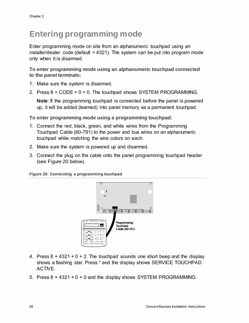
3. Connect the plug on the cable onto the panel programming touchpad header
(see Figure 20 below).
Figure 20: Connecting a programming touchpad
4. Press 8 + 4321 + 0 + 2. The touchpad sounds one short beep and the display
shows a flashing star. Press * and the display shows SERVICE TOUCHPAD
ACTIVE.
5. Press 8 + 4321 + 0 + 0 and the display shows SYSTEM PROGRAMMING.
Chapter 2
Concord Express Installation Instructions 29
6. After programming is completed, simply disconnect the touchpad from the
panel header.
Touchpad Button Programming Functions
In program mode, the touchpad buttons let you navigate to all installer
programming menus for configuring the system. Table 3 below describes the
touchpad button functions in program mode.
Table 3: Alphanumeric touchpad buttons
Button Programming function
# Selects menu item or data entry.
* Deselects menu item or data entry (if pressed before #).
A & B Scroll through available options at the current menu tier. Also scroll through
sensor text options during sensor text programming.
C Enters pauses when programming phone numbers.
D Deletes certain programmed settings.
0 thru 9 Enter numeric values wherever needed.
1 & 2 Select off (1) or on (2) wherever needed.
1 thru 6 Press and hold to enter alphabetical characters A thru F for account numbers.
7 or 9 Press and hold to enter * (7) or # (9) for phone numbers.
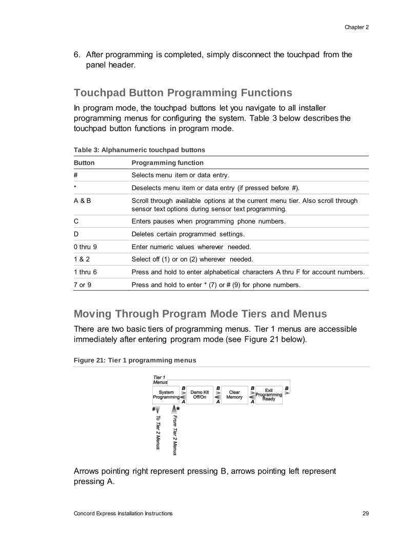
Moving Through Program Mode Tiers and Menus
There are two basic tiers of programming menus. Tier 1 menus are accessible
immediately after entering program mode (see Figure 21 below).
Figure 21: Tier 1 programming menus
Arrows pointing right represent pressing B, arrows pointing left represent
pressing A.
Chapter 2
30 Concord Express Installation Instructions
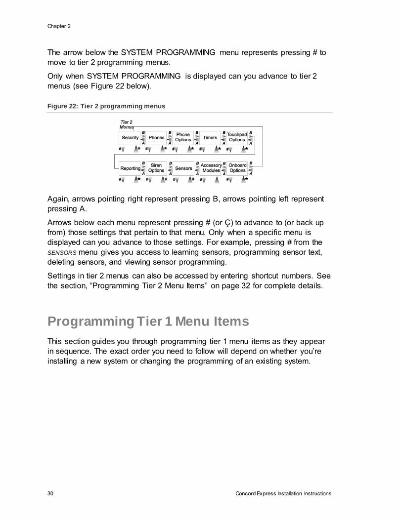
The arrow below the SYSTEM PROGRAMMING menu represents pressing # to
move to tier 2 programming menus.
Only when SYSTEM PROGRAMMING is displayed can you advance to tier 2
menus (see Figure 22 below).
Figure 22: Tier 2 programming menus
Again, arrows pointing right represent pressing B, arrows pointing left represent
pressing A.
Arrows below each menu represent pressing # (or Ç) to advance to (or back up
from) those settings that pertain to that menu. Only when a specific menu is
displayed can you advance to those settings. For example, pressing # from the
SENSORS menu gives you access to learning sensors, programming sensor text,
deleting sensors, and viewing sensor programming.
Settings in tier 2 menus can also be accessed by entering shortcut numbers. See
the section, “Programming Tier 2 Menu Items” on page 32 for complete details.
Programming Tier 1 Menu Items
This section guides you through programming tier 1 menu items as they appear
in sequence. The exact order you need to follow will depend on whether you’re
installing a new system or changing the programming of an existing system.
Chapter 2
Concord Express Installation Instructions 31
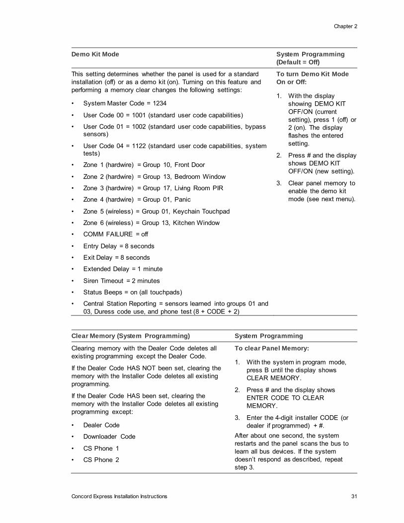
Demo Kit Mode System Programming
(Default = Off)
This setting determines whether the panel is used for a standard
installation (off) or as a demo kit (on). Turning on this feature and
performing a memory clear changes the following settings:
• System Master Code = 1234
• User Code 00 = 1001 (standard user code capabilities)
• User Code 01 = 1002 (standard user code capabilities, bypass sensors)
• User Code 04 = 1122 (standard user code capabilities, system tests)
• Zone 1 (hardwire) = Group 10, Front Door
• Zone 2 (hardwire) = Group 13, Bedroom Window
• Zone 3 (hardwire) = Group 17, Living Room PIR
• Zone 4 (hardwire) = Group 01, Panic
• Zone 5 (wireless) = Group 01, Keychain Touchpad
• Zone 6 (wireless) = Group 13, Kitchen Window
• COMM FAILURE = off
• Entry Delay = 8 seconds
• Exit Delay = 8 seconds
• Extended Delay = 1 minute
• Siren Timeout = 2 minutes
• Status Beeps = on (all touchpads)
• Central Station Reporting = sensors learned into groups 01 and
03, Duress code use, and phone test (8 + CODE + 2)
To turn Demo Kit Mode
On or Off:
1. With the display
showing DEMO KIT
OFF/ON (current
setting), press 1 (off) or
2 (on). The display
flashes the entered
setting.
2. Press # and the display
shows DEMO KIT
OFF/ON (new setting).
3. Clear panel memory to
enable the demo kit
mode (see next menu).
Clear Memory (System Programming) System Programming
Clearing memory with the Dealer Code deletes all
existing programming except the Dealer Code.
If the Dealer Code HAS NOT been set, clearing the
memory with the Installer Code deletes all existing
programming.
If the Dealer Code HAS been set, clearing the
memory with the Installer Code deletes all existing
programming except:
• Dealer Code
• Downloader Code
• CS Phone 1
• CS Phone 2
To clear Panel Memory:
1. With the system in program mode,
press B until the display shows
CLEAR MEMORY.
2. Press # and the display shows
ENTER CODE TO CLEAR
MEMORY.
3. Enter the 4-digit installer CODE (or
dealer if programmed) + #.
After about one second, the system
restarts and the panel scans the bus to
learn all bus devices. If the system
doesn’t respond as described, repeat
step 3.
Chapter 2
32 Concord Express Installation Instructions
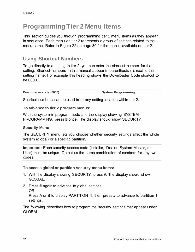
Programming Tier 2 Menu Items
This section guides you through programming tier 2 menu items as they appear
in sequence. Each menu on tier 2 represents a group of settings related to the
menu name. Refer to Figure 22 on page 30 for the menus available on tier 2.
Using Shortcut Numbers
To go directly to a setting in tier 2, you can enter the shortcut number for that
setting. Shortcut numbers in this manual appear in parenthesis ( ), next to the
setting name. For example this heading shows the Downloader Code shortcut to
be 0000.
Downloader code (0000) System Programming
Shortcut numbers can be used from any setting location within tier 2.
To advance to tier 2 program menus:
With the system in program mode and the display showing SYSTEM
PROGRAMMING, press # once. The display should show SECURITY.
Security Menu
The SECURITY menu lets you choose whether security settings affect the whole
system (global) or a specific partition.
Important: Each security access code (Installer, Dealer, System Master, or
User) must be unique. Do not us the same combination of numbers for any two
codes.
To access global or partition security menu items:
1. With the display showing SECURITY, press #. The display should show
GLOBAL.
2. Press # again to advance to global settings
OR
Press A or B to display PARTITION 1, then press # to advance to partition 1
settings.
The following describes how to program the security settings that appear under
GLOBAL.

Chapter 2
Concord Express Installation Instructions 33
Downloader Code (0000) Security-Global (Default = 12345)
The 5-digit downloader code is used in conjunction
with downloader programming. The down-loader
operator must have the panel account number and
downloader code in order to perform any
programming.
Note: The Downloader Code cannot be deleted from
panel memory. To change the Downloader Code to its default setting, enter 12345 in the procedure to the right. The Downloader Code will be reset to
defaults during a Memory Clear only if the Dealer Code is not set OR if the Dealer Code is used to initiate the Memory Clear.
To program a Downloader Code:
1. With the display showing
DOWNLOADER CODE nnnnn
(current code), enter the desired
5-digit code, + #. The display flashes
the entered code.
2. Press # and the display shows
DOWNLOADER CODE nnnnn (new
code).
Installer Code (0001) Security-Global (Default = 4321)
The 4-digit installer code is used for entering program
mode and changing system settings. If a dealer code
is programmed, only those settings not associated
with phone numbers can be changed.
Note: The Installer Code cannot be deleted or cleared from panel memory. To change the Installer Code to its default setting, enter 4321 in the procedure
above.
To program an Installer Code:
1. With the display showing INSTALLER
CODE nnnn (current code), enter the
desired 4-digit code + #. The display
flashes the entered code.
2. Press # and display shows
INSTALLER CODE nnnn (new code).
Dealer Code (0002) Security-Global (Default = none)
The 4-digit dealer code is used to prevent
unauthorized persons from changing the
programmed central station phone numbers
and the Downloader Access Code. When this
feature is enabled, central station phone
numbers and the Downloader Code cannot be
changed (unless you enter the program mode
by using the dealer code). All other system
settings are still accessible by entering the
program mode with the installer code.
To program a Dealer Code:
1. With the display showing DEALER CODE ****,
enter the desired 4-digit code. The display
flashes the entered setting.
2. Press # and the display shows the new
code.
To delete a Dealer Code:
With the display showing DEALER CODE nnnn
(current code), press D. The display shows
DEALER CODE ****.
Note: The Dealer Code cannot be deleted by
clearing panel memory.
Chapter 2
34 Concord Express Installation Instructions
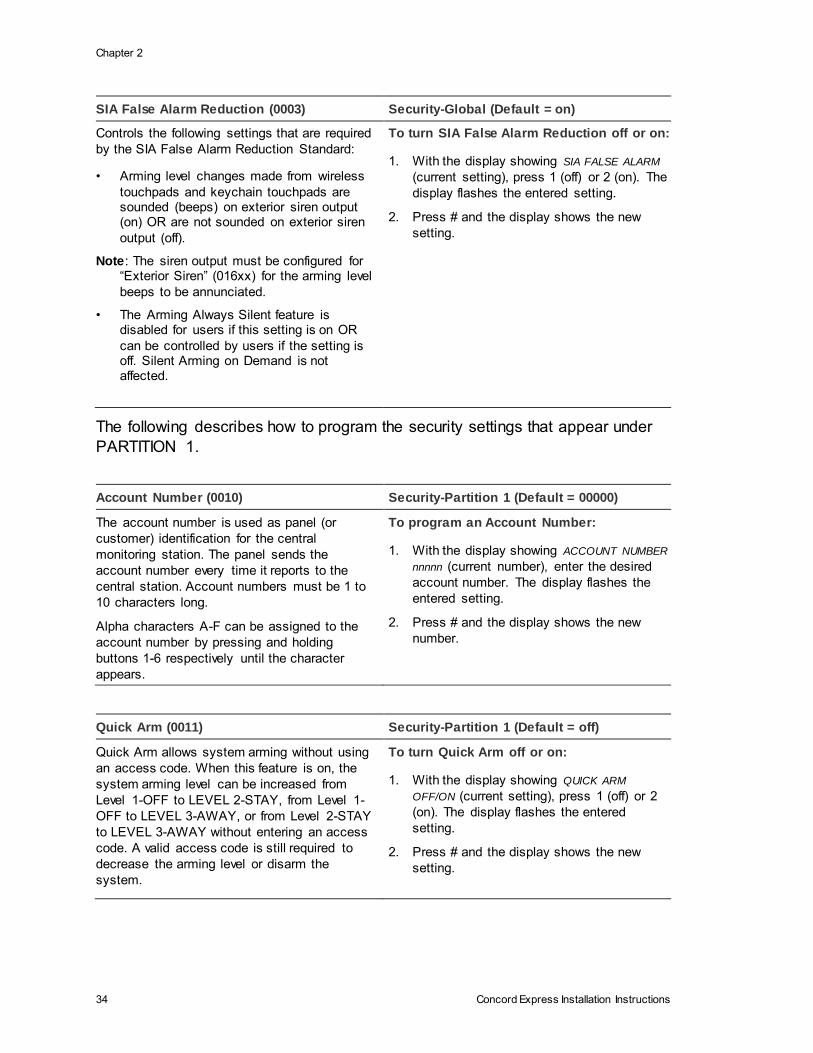
SIA False Alarm Reduction (0003) Security-Global (Default = on)
Controls the following settings that are required
by the SIA False Alarm Reduction Standard:
• Arming level changes made from wireless
touchpads and keychain touchpads are sounded (beeps) on exterior siren output (on) OR are not sounded on exterior siren
output (off).
Note: The siren output must be configured for “Exterior Siren” (016xx) for the arming level
beeps to be annunciated.
• The Arming Always Silent feature is disabled for users if this setting is on OR
can be controlled by users if the setting is off. Silent Arming on Demand is not affected.
To turn SIA False Alarm Reduction off or on:
1. With the display showing SIA FALSE ALARM
(current setting), press 1 (off) or 2 (on). The
display flashes the entered setting.
2. Press # and the display shows the new
setting.
The following describes how to program the security settings that appear under
PARTITION 1.
Account Number (0010) Security-Partition 1 (Default = 00000)
The account number is used as panel (or
customer) identification for the central
monitoring station. The panel sends the
account number every time it reports to the
central station. Account numbers must be 1 to
10 characters long.
Alpha characters A-F can be assigned to the
account number by pressing and holding
buttons 1-6 respectively until the character
appears.
To program an Account Number:
1. With the display showing ACCOUNT NUMBER
nnnnn (current number), enter the desired
account number. The display flashes the
entered setting.
2. Press # and the display shows the new
number.
Quick Arm (0011) Security-Partition 1 (Default = off)
Quick Arm allows system arming without using
an access code. When this feature is on, the
system arming level can be increased from
Level 1-OFF to LEVEL 2-STAY, from Level 1-
OFF to LEVEL 3-AWAY, or from Level 2-STAY
to LEVEL 3-AWAY without entering an access
code. A valid access code is still required to
decrease the arming level or disarm the
system.
To turn Quick Arm off or on:
1. With the display showing QUICK ARM
OFF/ON (current setting), press 1 (off) or 2
(on). The display flashes the entered
setting.
2. Press # and the display shows the new
setting.
Chapter 2
Concord Express Installation Instructions 35
Quick Exit (0012) Security-Partition 1 (Default =
on)
This setting determines whether or not users can open and
close a standard entry or exit door without causing an alarm
(while the system is armed). This feature would be useful if
the user wanted to go out to get the morning paper while the
system was armed. This feature also allows the user to leave
the armed premises without having to disarm and rearm the
system.
Note: For UL Listed systems, Quick Exit must be turned off.
When this feature is on, pressing D on a touchpad (while the
system is armed) starts a 2-minute timer that allows one
standard entry or exit door (sensor groups 10 and 19 only) to
be activated once (opened, then closed).When this feature is
turned off, the system must be disarmed before opening any
protected door.
To turn Quick Exit off or on:
1. With the display showing
QUICK EXIT OFF/ON (current
setting), press 1 (off) or 2
(on). The display flashes the
entered setting.
2. Press # and the display
shows the new setting.
Exit Extension (0013) Security-Partition 1 (Default =
on)
This setting determines whether or not the system
automatically arms to STAY (level 2) if the user arms the
system to AWAY (level 3) without exiting the premises. This
can help prevent accidental alarms by deactivating interior
motion sensors during occupied arming periods.
Note: Arming the system to AWAY with No Delay overrides
the Auto Stay Arming feature.
With the feature turned on, the user arms the system to
AWAY. Touchpads (and other status sounders) emit one exit
delay beep every four seconds, then one every second during
the last 10 seconds. If the exit delay time expires with no
standard delay sensor activation, the system automatically
arms to STAY.
To turn Auto Stay Arming off
or on:
1. With the display showing
AUTO STAY ARMING OFF/ON
(current setting), press 1 (off)
or 2 (on). The display flashes
the entered setting.
2. Press # and the display
shows the new setting.
Chapter 2
36 Concord Express Installation Instructions
Auto Stay Arming (0014) Security-Partition 1 (Default =
on)
This setting determines whether or not the system
automatically arms to STAY (level 2) if the user arms the
system to AWAY (level 3) without exiting the premises. This
can help prevent accidental alarms by deactivating interior
motion sensors during occupied arming periods.
Note: Arming the system to AWAY with No Delay overrides
the Auto Stay Arming feature.
With the feature turned on, the user arms the system to
AWAY. Touchpads (and other status sounders) emit one exit
delay beep every four seconds, then one every second during
the last 10 seconds. If the exit delay time expires with no
standard delay sensor activation, the system automatically
arms to STAY.
To turn Auto Stay Arming off
or on:
1. With the display showing
AUTO STAY ARMING OFF/ON
(current setting), press 1 (off)
or 2 (on). The display flashes
the entered setting.
2. Press # and the display
shows the new setting.
Keyswitch Sensor (0015) Security-Partition 1 (Default =
none)
This feature lets users arm and disarm the system using
either a keyswitch wired to a hardwire zone input or a
wireless door or window sensor.
For example, if sensor 1 is designated as the keyswitch
sensor and the system is disarmed, then tripping sensor 1
arms the system to AWAY. If the system is armed to STAY
or AWAY, tripping sensor 1 disarms the system. The panel
reports opening, closing, and force armed reports (if these
features are turned on) to the central monitoring station.
Note: A bypassed keyswitch sensor cannot arm or disarm
the system.
During an audible alarm, keyswitch sensors can disarm the
system (which sends a cancel report to the central
monitoring station), but cannot arm the system. The system
can be armed only after siren timeout expires.
Keyswitch sensors test the same as any other sensor and
do not arm or disarm the system during a sensor test.
To assign a Keyswitch Sensor:
1. With the display showing
KEYSWITCH SENSOR n (current
sensor number), enter the
desired sensor number (01-24).
The display flashes the entered
sensor number.
2. Press # and the display shows
the new number.

Chapter 2
Concord Express Installation Instructions 37
Duress code (0016) Security-Partition 1 (Default = none)
The duress code is a unique 4-digit access code that
allows users to operate the system and, at the same
time, instructs the panel to send a silent alarm report to
the central station.
Do not use a duress code unless it is absolutely
necessary. Using duress codes often results in false
alarms due to code entry errors. If a duress code is
absolutely necessary, use it with an Interrogator® audio
verification module (AVM) to reduce false alarms and
accidental dispatches.
Note: To use this feature, the Duress Option setting
under the REPORTING—PARTITION 1 menu must be
turned on.
To program a Duress Code:
1. With the display showing DURESS
CODE ****, enter the desired 4-digit
duress code. The display flashes
the entered setting.
2. Press # and the display shows the
new code.
To delete a Duress Code:
With the display showing DURESS CODE
nnnn (current code), press D. The
display shows DURESS CODE ****.
Phones Menu
The PHONES menu lets you set up central station reporting for the system
(global) and pager reports (partition specific). The following describes how to
program the settings that appear under CS PHONE 1-2.
Phone Number (0100-cs phone 1, 0110-
cs phone 2)
Phones-CS Phone 1-2 (Default = none)
(Default = none) This setting is used for
programming the central station receiver
phone number. Phone numbers can be 1-
24 digits long, including pauses or * and #
characters. To enter pauses, press C. To
enter *, press and hold 7 for one second.
To enter #, press and hold 9 for one
second.
Note: The PHONE NUMBER menus are
not accessible if a Dealer Code is
programmed and the Installer Code is used
to enter installer programming mode. To
access these menus when a Dealer Code
is programmed, you must enter installer
programming mode using the Dealer Code.
A phone number must be programmed for
UL 1635 listed installations.
To program a Central Station Phone Number:
1. With the display showing PHONE NUMBER _ (or
current number), enter the desired phone
number. The display flashes the entered
number.
2. Press # and the display shows the new number.
Note: Call-waiting services should be disabled to
prevent interruptions to panel communication to the
central monitoring station (or pager). To program a
dialing prefix that disables call-waiting, see the Call
Wait Cancel setting under the menu PHONE
OPTIONS—GLOBAL.
To delete a Central Station Phone Number:
With the display showing PHONE NUMBER n (current
number), press D. The display shows PHONE
NUMBER _.
Chapter 2
38 Concord Express Installation Instructions
High Level Rpts (0101-cs phone 1, 0111-cs
phone 2)
Phones-CS Phone 1-2 (Default: CS
Phone 1=on, CS Phone 2=off)
When this setting is on, the panel reports to the
central station events that involve a high-level
security risk, including the following conditions:
• Fire, Police, Auxiliary, Duress, and Freeze
alarms
• No Activity
• Receiver Failure (or jam)
• System Tamper (40 incorrect keystrokes or touchpad supervisory),
• Entering or exiting Sensor Test mode
Note: For UL 1635 listed installations, this feature
must be set to on for the programmed phone
number.
To turn High-Level Reports off or on:
1. With the display showing HIGH LEVEL
RPTS OFF/ON (current setting), press 1
(off) or 2 (on). The display flashes the
entered setting.
2. Press # and the display shows the new
setting.
Low Level Rpts (0102-cs phone 1, 0112-cs
phone 2)
Phones-CS Phone 1-2 (Default: CS
Phone 1=on, CS Phone 2=off)
When this setting is on, the panel reports non-alarm
conditions to the central station, including the
following conditions:
• Force Armed
• Hardwire Zone Trouble (open or short)
• Supervisory (wireless devices)
• Low Battery (wireless devices)
• Other non-alarm related conditions
Note: For UL 1635 listed installations, this feature
must be set to on for the programmed phone
number.
To turn Low-Level Reports off or on:
1. With the display showing LOW LEVEL
RPTS OFF/ON (current setting), press 1
(off) or 2 (on). The display flashes the
entered setting.
2. Press # and the display shows the new
setting.
Open/Close Rpts (0103-cs phone 1,
0113-cs phone 2)
Phones-CS Phone 1-2 (Default=off)
When this setting is on, the panel sends a
report when the system is armed (closed)
or disarmed (opened).
Note: To use this feature, the Opening
Reports and Closing Reports settings under
the REPORTING menu must be turned on.
To turn Opening/Closing Reports off or on:
1. With the display showing OPEN/CLOSE RPTS
OFF/ON (current setting), press 1 (off) or 2 (on).
The display flashes the entered setting.
2. Press # and the display shows the new setting.
Chapter 2
Concord Express Installation Instructions 39
Backup (0104-cs phone 1, 0114-cs phone 2) Phones-CS Phone 1-2 (Default: CS
Phone 1=on, CS Phone 2=off)
This setting determines whether or not the panel uses
another programmed central station phone number for
reporting if three initial attempts are unsuccessful.
CS Phone 1 is backed up by CS Phone 2, and CS Phone
2 is backed up by CS Phone 1. The panel makes up to 16
attempts (8 per phone number), alternating between the
two programmed phone numbers.
For example, if Backup is on and three failed reporting
attempts occur using CS Phone 1, the panel switches to
CS Phone 2 for three more reporting attempts. If these
attempts fail, the panel switches back to CS Phone 1 for
five more reporting attempts and, if necessary, switches
back to CS Phone 2 for five final attempts.
To turn Backup off or on:
1. With the display showing BACKUP
OFF/ON (current setting), press 1
(off) or 2 (on). The display
flashes the entered setting.
2. Press # and the display shows
the new setting.
Reporting Format (0105-cs phone 1,
0115-cs phone 2)
Phones-CS Phone 1-2 (Default=all CID)
This setting determines whether the
panel uses the SIA or CID (Contact ID)
reporting format for central station
communication.
To select SIA or CID Reporting Format:
1. With the display showing REPORTING FORMAT
SIA/CID (current setting), press 1 (for SIA) or 2 (for
CID). The display flashes the entered setting.
2. Press # and the display shows the new setting.
The following describes how to program the phone settings that appear under
PAGER PHONE 1-3.
Phone Number (0120-pager 1, 0130-pager 2,
0140-pager 3)
Phones-Pager Phone 1-3 (Default=none)
This setting is used for programming a phone
number that communicates to a pager. Phone
numbers can be 1-24 digits long, and can include
pauses or * and # characters.
To enter pauses, press C. To enter *, press and
hold 7 for one second. To enter #, press and hold
9 for one second.
Note: Call-waiting services should be disabled to
prevent interruptions to panel communication to
the central monitoring station (or pager). To
program a dialing prefix that disables call-waiting,
see the Call Wait Cancel setting under the menu
PHONE OPTIONS—GLOBAL.
To program a Pager Phone Number:
1. With the display showing PHONE NUMBER
_ (or current number), enter the desired
pager phone number including pauses.
The display flashes the entered number.
2. Press # and the display shows the new
number.
To delete a Pager Phone Number:
With the display showing PHONE NUMBER _
(current number), press D. The display shows
PHONE NUMBER _.

Chapter 2
40 Concord Express Installation Instructions
High Level Rpts (0121-pager 1, 0131-pager 2, 0141-
pager 3)
Phones-Pager Phone 1-3
(Default=on)
When this setting is on, the panel reports to the pager
events that involve a high-level security risk, including
the following conditions:
• Fire, Police, Auxiliary, Duress, and Freeze alarms
• No Activity
• Receiver Failure (or jam)
• System Tamper (40 incorrect keystrokes or
touchpad supervisory),
• Entering or exiting Sensor Test mode
To turn High-Level Reports off or on:
1. With the display showing HIGH
LEVEL RPTS OFF/ON (current
setting), press 1 (off) or 2 (on). The
display flashes the entered setting.
2. Press # and the display shows the
new setting.
Low Level Rpts (0122-pager 1, 0132-pager 2, 0142-
pager 3)
Phones-Pager Phone 1-3
(Default=off)
When this setting is on, the panel reports non-alarm
conditions to the pager, including the following conditions:
• Force Armed
• Hardwire Zone Trouble (open or short)
• Supervisory (wireless devices)
• Low Battery (wireless devices)
• Other non-alarm related conditions
To turn Low-Level Reports off or
on:
1. With the display showing LOW
LEVEL RPTS OFF/ON (current
setting), press 1 (off) or 2 (on).
The display flashes the entered
setting.
2. Press # and the display shows
LOW LEVEL RPTS OFF/ON (new
setting).
Open/Close Rpts (0123-pager 1, 0133-
pager 2, 0143-pager 3)
Phones-Pager Phone 1-3 (Default=off)
When this setting is on, the panel sends a
report when the system is armed (closed)
or disarmed (opened).
Note: To use this feature, the Opening
Reports and Closing Reports settings
under the REPORTING menu must be
turned on.
To turn Opening/Closing Reports off or on:
1. With the display showing OPEN/CLOSE RPTS
OFF/ON (current setting), press 1 (off) or 2 (on).
The display flashes the entered setting.
2. Press # and the display shows the new setting.
Chapter 2
Concord Express Installation Instructions 41
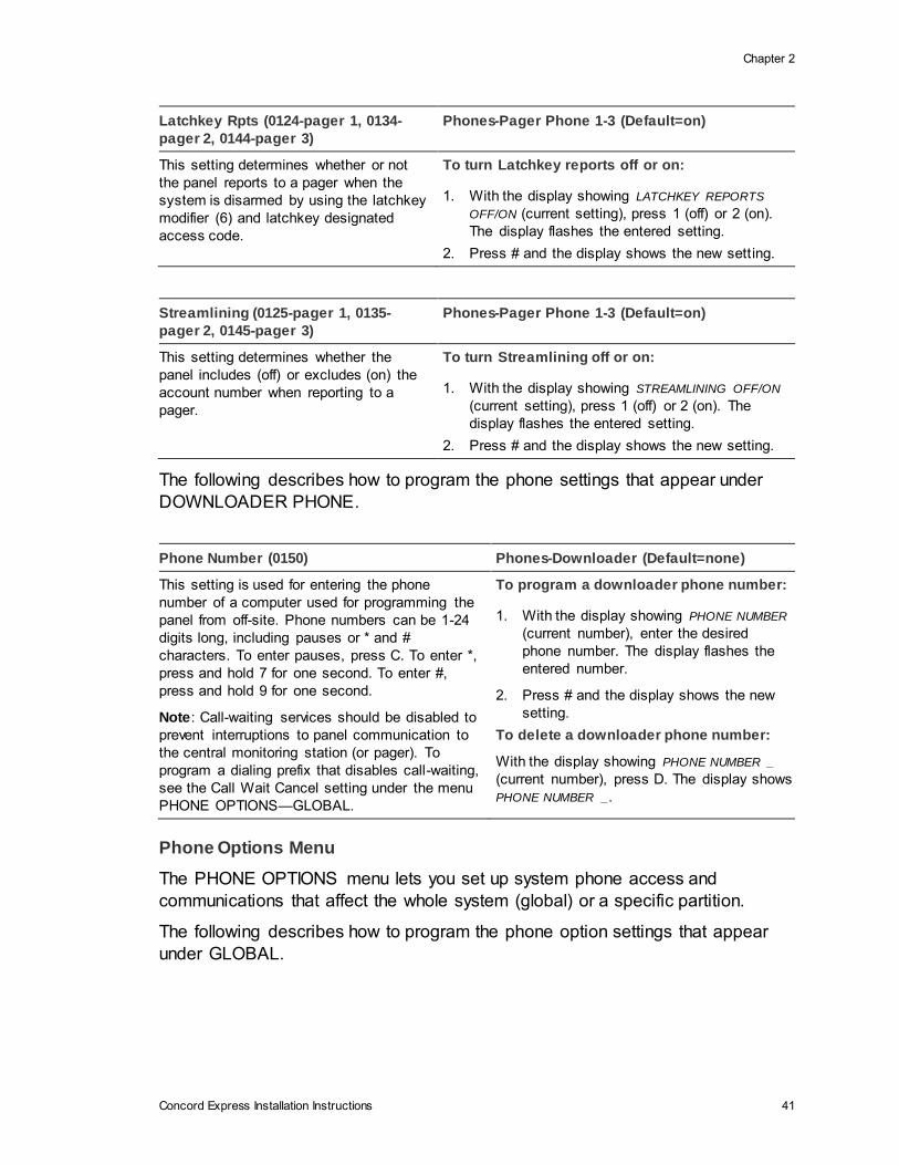
Latchkey Rpts (0124-pager 1, 0134-
pager 2, 0144-pager 3)
Phones-Pager Phone 1-3 (Default=on)
This setting determines whether or not
the panel reports to a pager when the
system is disarmed by using the latchkey
modifier (6) and latchkey designated
access code.
To turn Latchkey reports off or on:
1. With the display showing LATCHKEY REPORTS
OFF/ON (current setting), press 1 (off) or 2 (on).
The display flashes the entered setting.
2. Press # and the display shows the new setting.
Streamlining (0125-pager 1, 0135-
pager 2, 0145-pager 3)
Phones-Pager Phone 1-3 (Default=on)
This setting determines whether the
panel includes (off) or excludes (on) the
account number when reporting to a
pager.
To turn Streamlining off or on:
1. With the display showing STREAMLINING OFF/ON
(current setting), press 1 (off) or 2 (on). The
display flashes the entered setting.
2. Press # and the display shows the new setting.
The following describes how to program the phone settings that appear under
DOWNLOADER PHONE.
Phone Number (0150) Phones-Downloader (Default=none)
This setting is used for entering the phone
number of a computer used for programming the
panel from off-site. Phone numbers can be 1-24
digits long, including pauses or * and #
characters. To enter pauses, press C. To enter *,
press and hold 7 for one second. To enter #,
press and hold 9 for one second.
Note: Call-waiting services should be disabled to
prevent interruptions to panel communication to
the central monitoring station (or pager). To
program a dialing prefix that disables call-waiting,
see the Call Wait Cancel setting under the menu
PHONE OPTIONS—GLOBAL.
To program a downloader phone number:
1. With the display showing PHONE NUMBER
(current number), enter the desired
phone number. The display flashes the
entered number.
2. Press # and the display shows the new
setting.
To delete a downloader phone number:
With the display showing PHONE NUMBER _
(current number), press D. The display shows
PHONE NUMBER _.
Phone Options Menu
The PHONE OPTIONS menu lets you set up system phone access and
communications that affect the whole system (global) or a specific partition.
The following describes how to program the phone option settings that appear
under GLOBAL.

Chapter 2
42 Concord Express Installation Instructions
Phone Test (02000) Phones Options-Global (Default=on)
This setting determines if the user can test
the communication from the panel to the
central station (or a pager). When this feature
is on, the user can test communications at
any time by entering 8 + CODE + 2.
Note: For UL 1635 listed installations, this
feature must be set to on.
To turn the Phone Test setting off or on:
1. With the display showing PHONE TEST OFF/ON
(current setting), press 1 (off) or 2 (on). The
display flashes the entered setting.
2. Press # and the display shows the new
setting.
Auto Phone Test (02001) Phones Options-Global (Default=off)
This setting determines if the panel sends a
phone test automatically to the central station
(or a pager) on a predetermined schedule.
(Refer to the “Phone Test Freq.” and “Next
Phone Test” settings found under TIMERS—
GLOBAL).
Note: For UL 1635 listed installations, this
feature must be set to on.
To turn Automatic Phone Test off or on:
1. With the display showing AUTO PHONE TEST
OFF/ON (current setting), press 1 (off) or 2
(on). The display flashes the entered setting.
2. Press # and the display shows the new
setting.
Auto Test Reset (02002) Phones Options-Global
(Default=on)
This setting determines whether or not the Auto Phone Test
interval is reset after any successful report to the central
monitoring station. Refer to the “Phone Test Freq.” and
“Next Phone Test” settings found under TIMERS—
GLOBAL.
When this feature is on, the panel considers any successful
report to the central station to be a successful phone test.
Thus, any successful panel report to the central monitoring
station resets the Next Phone Test setting to the Phone
Test Freq. value. The panel only conducts an Auto Phone
Test if no other reports are made during the Phone Test
Freq. time period.
When this feature is off, an Auto Phone Test is always
conducted according to the Phone Test Freq. setting, even
if the panel makes other reports to the central monitoring
station during that time period.
Note: Phone Test Freq must be set to 2 or higher for this
feature to work.
To turn Auto Test Reset off or
on:
1. With the display showing AUTO
TEST RESET OFF/ON (current
setting), press 1 (off) or 2 (on).
The display flashes the entered
setting.
2. Press # and the display shows
the new setting.
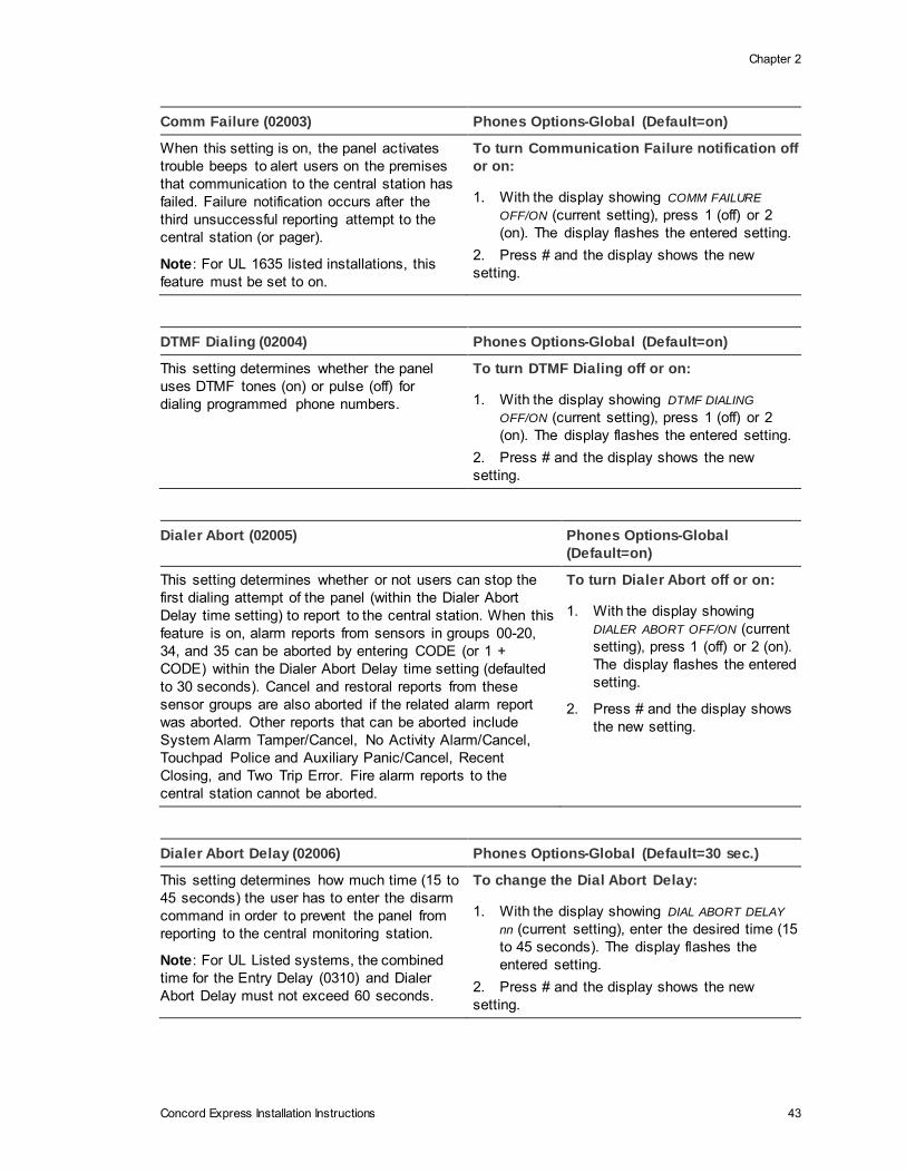
Chapter 2
Concord Express Installation Instructions 43
Comm Failure (02003) Phones Options-Global (Default=on)
When this setting is on, the panel activates
trouble beeps to alert users on the premises
that communication to the central station has
failed. Failure notification occurs after the
third unsuccessful reporting attempt to the
central station (or pager).
Note: For UL 1635 listed installations, this
feature must be set to on.
To turn Communication Failure notification off
or on:
1. With the display showing COMM FAILURE
OFF/ON (current setting), press 1 (off) or 2
(on). The display flashes the entered setting.
2. Press # and the display shows the new
setting.
DTMF Dialing (02004) Phones Options-Global (Default=on)
This setting determines whether the panel
uses DTMF tones (on) or pulse (off) for
dialing programmed phone numbers.
To turn DTMF Dialing off or on:
1. With the display showing DTMF DIALING
OFF/ON (current setting), press 1 (off) or 2
(on). The display flashes the entered setting.
2. Press # and the display shows the new
setting.
Dialer Abort (02005) Phones Options-Global
(Default=on)
This setting determines whether or not users can stop the
first dialing attempt of the panel (within the Dialer Abort
Delay time setting) to report to the central station. When this
feature is on, alarm reports from sensors in groups 00-20,
34, and 35 can be aborted by entering CODE (or 1 +
CODE) within the Dialer Abort Delay time setting (defaulted
to 30 seconds). Cancel and restoral reports from these
sensor groups are also aborted if the related alarm report
was aborted. Other reports that can be aborted include
System Alarm Tamper/Cancel, No Activity Alarm/Cancel,
Touchpad Police and Auxiliary Panic/Cancel, Recent
Closing, and Two Trip Error. Fire alarm reports to the
central station cannot be aborted.
To turn Dialer Abort off or on:
1. With the display showing
DIALER ABORT OFF/ON (current
setting), press 1 (off) or 2 (on).
The display flashes the entered
setting.
2. Press # and the display shows
the new setting.
Dialer Abort Delay (02006) Phones Options-Global (Default=30 sec.)
This setting determines how much time (15 to
45 seconds) the user has to enter the disarm
command in order to prevent the panel from
reporting to the central monitoring station.
Note: For UL Listed systems, the combined
time for the Entry Delay (0310) and Dialer
Abort Delay must not exceed 60 seconds.
To change the Dial Abort Delay:
1. With the display showing DIAL ABORT DELAY
nn (current setting), enter the desired time (15
to 45 seconds). The display flashes the
entered setting.
2. Press # and the display shows the new
setting.

Chapter 2
44 Concord Express Installation Instructions
Cancel Message (02007) Phones Options-Global (Default=on)
This setting determines whether or not the
panel displays a cancel message after the
user disarms the system to clear an alarm
condition.
To turn Cancel Message off or on:
1. With the display showing CANCEL
MESSAGE OFF/ON (current setting), press 1
(off) or 2 (on). The display flashes the entered
setting.
2. Press # and the display shows the new
setting.
Pager Delay (02008) Phones Options-Global (Default=15 sec.)
This setting determines how long a report is
delayed to a pager (00-30 seconds) after the
panel dials the pager number.
Note: The Pager Delay time should not be
set below 5 seconds unless absolutely
necessary.
To set the Pager Delay time:
1. With the display showing PAGER DELAY nn
(current setting), enter a two-digit time (00-
30). The display flashes the entered setting.
2. Press É and the display shows the new
setting.
Call Wait Cancel (02009) Phones Options-Global
(Default=none)
This feature lets you set up a dialing prefix to disable the call
waiting feature before the panel makes its first dialing attempt to
any programmed central monitoring station, pager, or downloader
phone number. The prefix can be up to eight digits. For prefixes
that require dialing * or #, press and hold for two seconds 7 (for *)
or 9 (for #).
Caution: DO NOT change this option from its default if the
customer doesn’t have call waiting. Verify with the customer that
they have call waiting with their phone service provider before
changing this option from its default. Changing this option from its
default without call waiting will prohibit the panel from calling the
central station.
To set up Call Wait Cancel:
1. With the display showing
CALL WAIT CANCEL __ (or
current setting), enter the
desired prefix. The
display flashes the
entered setting.
2. Press # and the display
shows the new setting.
The following describes how to program the PHONE OPTION settings that
appear under PARTITION 1.
Remote Access (0210) Phones Options-Partition 1 (Default=on)
This setting determines whether or not the
panel can be accessed from off-site for
downloader programming.
To turn Remote Access off or on:
1. With the display showing REMOTE ACCESS
OFF/ON (current setting), press 1 (off) or 2 (on).
The display flashes the entered setting.
2. Press # and the display shows the new setting.
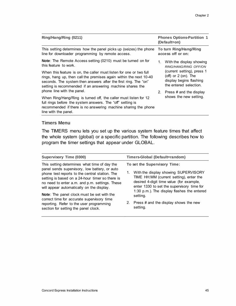
Chapter 2
Concord Express Installation Instructions 45
Ring/Hang/Ring (0211) Phones Options-Partition 1
(Default=on)
This setting determines how the panel picks up (seizes) the phone
line for downloader programming by remote access.
Note: The Remote Access setting (0210) must be turned on for
this feature to work.
When this feature is on, the caller must listen for one or two full
rings, hang up, then call the premises again within the next 10-40
seconds. The system then answers after the first ring. The “on”
setting is recommended if an answering machine shares the
phone line with the panel.
When Ring/Hang/Ring is turned off, the caller must listen for 12
full rings before the system answers. The “off” setting is
recommended if there is no answering machine sharing the phone
line with the panel.
To turn Ring/Hang/Ring
access off or on:
1. With the display showing
RING/HANG/RING OFF/ON
(current setting), press 1
(off) or 2 (on). The
display begins flashing
the entered selection.
2. Press # and the display
shows the new setting.
Timers Menu
The TIMERS menu lets you set up the various system feature times that affect
the whole system (global) or a specific partition. The following describes how to
program the timer settings that appear under GLOBAL.
Supervisory Time (0300) Timers-Global (Default=random)
This setting determines what time of day the
panel sends supervisory, low battery, or auto
phone test reports to the central station. The
setting is based on a 24-hour timer so there is
no need to enter a.m. and p.m. settings. These
will appear automatically on the display.
Note: The panel clock must be set with the
correct time for accurate supervisory time
reporting. Refer to the user programming
section for setting the panel clock.
To set the Supervisory Time:
1. With the display showing SUPERVISORY
TIME HH:MM (current setting), enter the
desired 4-digit time value (for example,
enter 1330 to set the supervisory time for
1:30 p.m.). The display flashes the entered
setting.
2. Press # and the display shows the new
setting.

Chapter 2
46 Concord Express Installation Instructions
RF Tx Timeout (0301) Timers-Global (Default=12 hours)
If any supervised wireless device stops sending
supervisory transmissions, the panel reports a
supervisory condition to the central station. This
setting determines how long the panel should wait
(2-24 hours) for a supervisory transmission before
sending the report.
Note: For UL 985 & 1635 listed installations, the
RF Tx Timeout must be set to 4 hours. For UL
1023 listed installations, the RF Tx Timeout must
be set to 24 hours.
To set the RF Tx Timeout:
1. With the display showing RF TX
TIMEOUT nn HOURS (current setting),
enter the desired 2-digit timeout value
(02-24). The display flashes the entered
setting.
2. Press # and the display shows the new
setting.
Phone Test Freq. (0302) Timers-Global (Default=7 days)
This setting determines how often the panel
sends the automatic phone test (see “Auto
Phone Test” under PHONE OPTIONS—
GLOBAL) to the central station (or a pager).
The phone test frequency can be set to report
every 1 to 255 days.
Note: For UL 1635 listed installations, this
feature must be set to 1.
To set the Phone Test Freq:
1. With the display showing PHONE TEST
FREQ nnn DAYS (current setting), enter
the number of days (1-255). The display
flashes the entered setting.
2. Press # and the display shows the new
setting.
Next Phone Test (0303) Timers-Global (Default=7 days)
This setting determines how many days (1-255)
until the next automatic phone test occurs.
When setting up Phone Test Freq, Next Phone
Test must be set to accurately count the
number of days left in the cycle before the next
phone test occurs. This setting should be the
same or less than the Phone Test Freq. setting.
Note: For UL 1635 listed installations, this
feature must be set to 1.
To set the Next Phone Test:
1. With the display showing NEXT PHONE
TEST nnn DAYS (current setting), enter the
number of days (1-255). The display
flashes the entered setting.
2. Press # and the display shows the new
setting.
Output Trip Time (0304) Timers-Global (Default=4 sec.)
This setting determines how long onboard
and SnapCard outputs are activated when
tripped (if they are configured for a
momentary response).
To set the Output Trip Time:
1. With the display showing OUTPUT TRIP TIME
nn SECONDS (current setting), enter the
number of seconds (1-12). The display flashes
the entered setting.
2. Press # and the display shows the new setting.
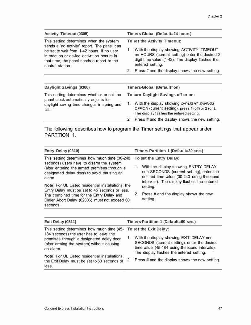
Chapter 2
Concord Express Installation Instructions 47
Activity Timeout (0305) Timers-Global (Default=24 hours)
This setting determines when the system
sends a “no activity” report. The panel can
be set to wait from 1-42 hours. If no user
interaction or device activation occurs in
that time, the panel sends a report to the
central station.
To set the Activity Timeout:
1. With the display showing ACTIVITY TIMEOUT
nn HOURS (current setting) enter the desired 2-
digit time value (1-42). The display flashes the
entered setting.
2. Press # and the display shows the new setting.
Daylight Savings (0306) Timers-Global (Default=on)
This setting determines whether or not the
panel clock automatically adjusts for
daylight saving time changes in spring and
fall.
To turn Daylight Savings off or on:
1. With the display showing DAYLIGHT SAVINGS
OFF/ON (current setting), press 1 (off) or 2 (on).
The display flashes the entered setting.
2. Press # and the display shows the new setting.
The following describes how to program the Timer settings that appear under
PARTITION 1.
Entry Delay (0310) Timers-Partition 1 (Default=30 sec.)
This setting determines how much time (30-240
seconds) users have to disarm the system
(after entering the armed premises through a
designated delay door) to avoid causing an
alarm.
Note: For UL Listed residential installations, the
Entry Delay must be set to 45 seconds or less.
The combined time for the Entry Delay and
Dialer Abort Delay (02006) must not exceed 60
seconds.
To set the Entry Delay:
1. With the display showing ENTRY DELAY
nnn SECONDS (current setting), enter the
desired time value (30-240 using 8-second
intervals). The display flashes the entered
setting.
2. Press # and the display shows the new
setting.
Exit Delay (0311) Timers-Partition 1 (Default=60 sec.)
This setting determines how much time (45-
184 seconds) the user has to leave the
premises through a designated delay door
(after arming the system) without causing
an alarm.
Note: For UL Listed residential installations,
the Exit Delay must be set to 60 seconds or
less.
To set the Exit Delay:
1. With the display showing EXIT DELAY nnn
SECONDS (current setting), enter the desired
time value (45-184 using 8-second intervals).
The display flashes the entered setting.
2. Press # and the display shows the new setting.
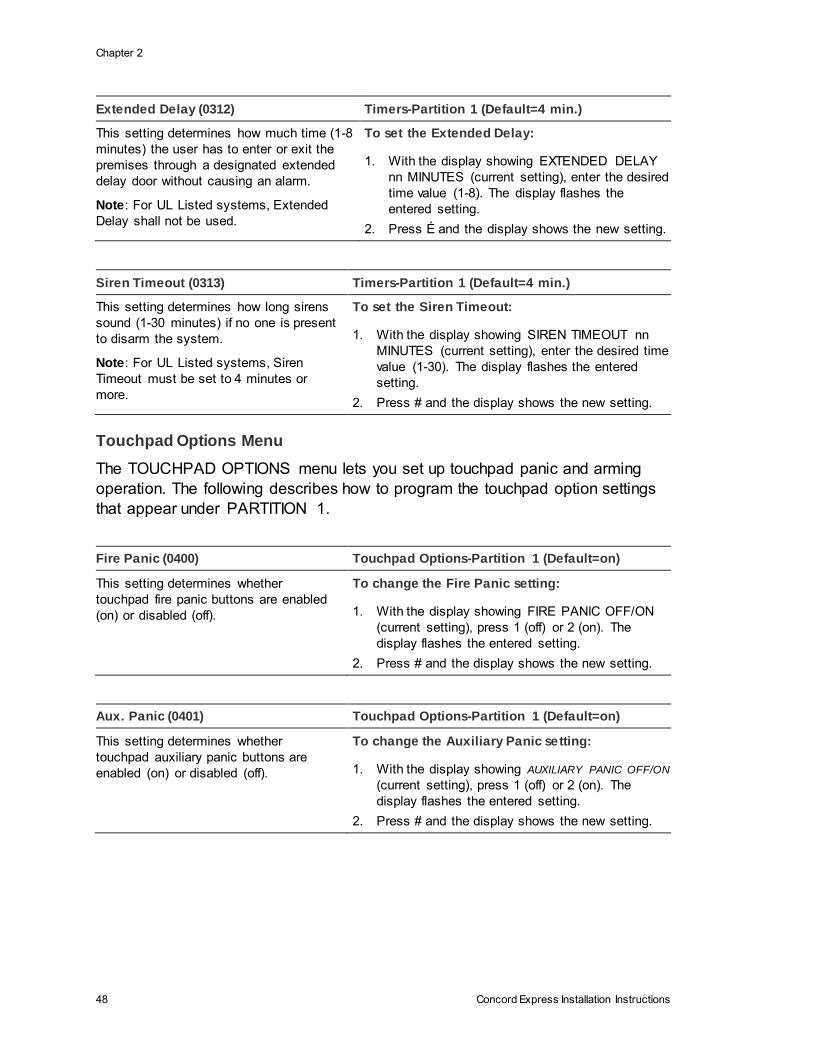
Chapter 2
48 Concord Express Installation Instructions
Extended Delay (0312) Timers-Partition 1 (Default=4 min.)
This setting determines how much time (1-8
minutes) the user has to enter or exit the
premises through a designated extended
delay door without causing an alarm.
Note: For UL Listed systems, Extended
Delay shall not be used.
To set the Extended Delay:
1. With the display showing EXTENDED DELAY
nn MINUTES (current setting), enter the desired
time value (1-8). The display flashes the
entered setting.
2. Press É and the display shows the new setting.
Siren Timeout (0313) Timers-Partition 1 (Default=4 min.)
This setting determines how long sirens
sound (1-30 minutes) if no one is present
to disarm the system.
Note: For UL Listed systems, Siren
Timeout must be set to 4 minutes or
more.
To set the Siren Timeout:
1. With the display showing SIREN TIMEOUT nn
MINUTES (current setting), enter the desired time
value (1-30). The display flashes the entered
setting.
2. Press # and the display shows the new setting.
Touchpad Options Menu
The TOUCHPAD OPTIONS menu lets you set up touchpad panic and arming
operation. The following describes how to program the touchpad option settings
that appear under PARTITION 1.
Fire Panic (0400) Touchpad Options-Partition 1 (Default=on)
This setting determines whether
touchpad fire panic buttons are enabled
(on) or disabled (off).
To change the Fire Panic setting:
1. With the display showing FIRE PANIC OFF/ON
(current setting), press 1 (off) or 2 (on). The
display flashes the entered setting.
2. Press # and the display shows the new setting.
Aux. Panic (0401) Touchpad Options-Partition 1 (Default=on)
This setting determines whether
touchpad auxiliary panic buttons are
enabled (on) or disabled (off).
To change the Auxiliary Panic setting:
1. With the display showing AUXILIARY PANIC OFF/ON
(current setting), press 1 (off) or 2 (on). The
display flashes the entered setting.
2. Press # and the display shows the new setting.
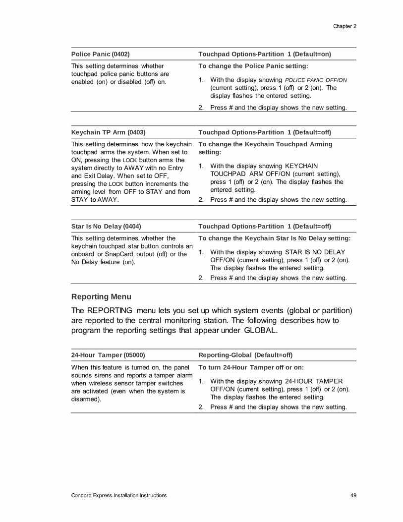
Chapter 2
Concord Express Installation Instructions 49
Police Panic (0402) Touchpad Options-Partition 1 (Default=on)
This setting determines whether
touchpad police panic buttons are
enabled (on) or disabled (off) on.
To change the Police Panic setting:
1. With the display showing POLICE PANIC OFF/ON
(current setting), press 1 (off) or 2 (on). The
display flashes the entered setting.
2. Press # and the display shows the new setting.
Keychain TP Arm (0403) Touchpad Options-Partition 1 (Default=off)
This setting determines how the keychain
touchpad arms the system. When set to
ON, pressing the LOCK button arms the
system directly to AWAY with no Entry
and Exit Delay. When set to OFF,
pressing the LOCK button increments the
arming level from OFF to STAY and from
STAY to AWAY.
To change the Keychain Touchpad Arming
setting:
1. With the display showing KEYCHAIN
TOUCHPAD ARM OFF/ON (current setting),
press 1 (off) or 2 (on). The display flashes the
entered setting.
2. Press # and the display shows the new setting.
Star Is No Delay (0404) Touchpad Options-Partition 1 (Default=off)
This setting determines whether the
keychain touchpad star button controls an
onboard or SnapCard output (off) or the
No Delay feature (on).
To change the Keychain Star Is No Delay setting:
1. With the display showing STAR IS NO DELAY
OFF/ON (current setting), press 1 (off) or 2 (on).
The display flashes the entered setting.
2. Press # and the display shows the new setting.
Reporting Menu
The REPORTING menu lets you set up which system events (global or partition)
are reported to the central monitoring station. The following describes how to
program the reporting settings that appear under GLOBAL.
24-Hour Tamper (05000) Reporting-Global (Default=off)
When this feature is turned on, the panel
sounds sirens and reports a tamper alarm
when wireless sensor tamper switches
are activated (even when the system is
disarmed).
To turn 24-Hour Tamper off or on:
1. With the display showing 24-HOUR TAMPER
OFF/ON (current setting), press 1 (off) or 2 (on).
The display flashes the entered setting.
2. Press # and the display shows the new setting.
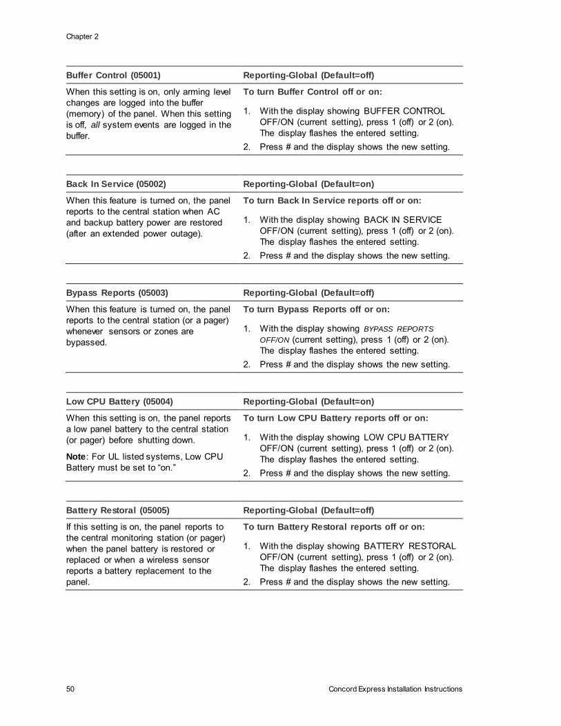
Chapter 2
50 Concord Express Installation Instructions
Buffer Control (05001) Reporting-Global (Default=off)
When this setting is on, only arming level
changes are logged into the buffer
(memory) of the panel. When this setting
is off, all system events are logged in the
buffer.
To turn Buffer Control off or on:
1. With the display showing BUFFER CONTROL
OFF/ON (current setting), press 1 (off) or 2 (on).
The display flashes the entered setting.
2. Press # and the display shows the new setting.
Back In Service (05002) Reporting-Global (Default=on)
When this feature is turned on, the panel
reports to the central station when AC
and backup battery power are restored
(after an extended power outage).
To turn Back In Service reports off or on:
1. With the display showing BACK IN SERVICE
OFF/ON (current setting), press 1 (off) or 2 (on).
The display flashes the entered setting.
2. Press # and the display shows the new setting.
Bypass Reports (05003) Reporting-Global (Default=off)
When this feature is turned on, the panel
reports to the central station (or a pager)
whenever sensors or zones are
bypassed.
To turn Bypass Reports off or on:
1. With the display showing BYPASS REPORTS
OFF/ON (current setting), press 1 (off) or 2 (on).
The display flashes the entered setting.
2. Press # and the display shows the new setting.
Low CPU Battery (05004) Reporting-Global (Default=on)
When this setting is on, the panel reports
a low panel battery to the central station
(or pager) before shutting down.
Note: For UL listed systems, Low CPU
Battery must be set to “on.”
To turn Low CPU Battery reports off or on:
1. With the display showing LOW CPU BATTERY
OFF/ON (current setting), press 1 (off) or 2 (on).
The display flashes the entered setting.
2. Press # and the display shows the new setting.
Battery Restoral (05005) Reporting-Global (Default=off)
If this setting is on, the panel reports to
the central monitoring station (or pager)
when the panel battery is restored or
replaced or when a wireless sensor
reports a battery replacement to the
panel.
To turn Battery Restoral reports off or on:
1. With the display showing BATTERY RESTORAL
OFF/ON (current setting), press 1 (off) or 2 (on).
The display flashes the entered setting.
2. Press # and the display shows the new setting.

Chapter 2
Concord Express Installation Instructions 51
Buffer Full Rpt (05006) Reporting-Global (Default=off)
When this setting is turned on, the panel
sends an “event buffer full” report to the
central monitoring station when the panel
event buffer (memory) is nearly full.
To turn Buffer Full Report off or on:
1. With the display showing BUFFER FULL RPT
OFF/ON (current setting), press 1 (off) or 2 (on).
The display flashes the entered setting.
2. Press # and the display shows the new setting.
Zone Restorals (05007) Reporting-Global (Default=off)
When this setting is on, the panel reports
a restoral to the central monitoring station
(or pager) when wireless or hardwire
zones in alarm are reset or “restored”
before the alarm is canceled.
Note: As with all UTC panels, hardwire
smoke detectors connected to Concord
or SnapCard hardwire zones do not send
restorals.
To turn Zone Restoral reporting off or on:
1. With the display showing ZONE RESTORALS
OFF/ON (current setting), press 1 (off) or 2 (on).
The display flashes the entered setting.
2. Press # and the display shows the new setting.
Two Trip Error (05008) Reporting-Global (Default=off)
This setting works with the “Alarm Verify” feature. If Alarm
Verify is turned on, then the panel waits for a second sensor
trip before sending an alarm (see “Appendix A: Table A3.
Sensor Group Characteristics”).
If Two Trip Error is also on and a second sensor trip does
not occur within a 4-minute time period, then the panel
sends an error report to the central monitoring station.
When this feature is turned off, the panel does not send
“Two Trip Error” reports.
Note: For UL Listed systems, Two Trip Error must be turned
off.
To turn Two Trip Error off or on:
1. With the display showing TWO
TRIP ERROR OFF/ON (current
setting), press 1 (off) or 2 (on).
The display flashes the entered
setting.
2. Press # and the display shows
the new setting.
TP Panic RPT FMT (05009) Reporting-Global (Default=off)
This setting determines how the panel formats
touchpad panic alarms reports to the central station.
When this feature is on, touchpad panic alarms report
using the following 3-digit codes:
Auxiliary—597, Police—598, Fire—599
When turned off, touchpad panic alarms report using a
3-digit code from 500 to 503 with the last digit
identifying the touchpad device number.
To turn TP Panic RPT FMT off or on:
1. With the display showing TP
PANIC RPT FMT OFF/ON (current
setting), press 1 (off) or 2 (on). The
display flashes the entered setting.
2. Press # and the display shows the
new setting.
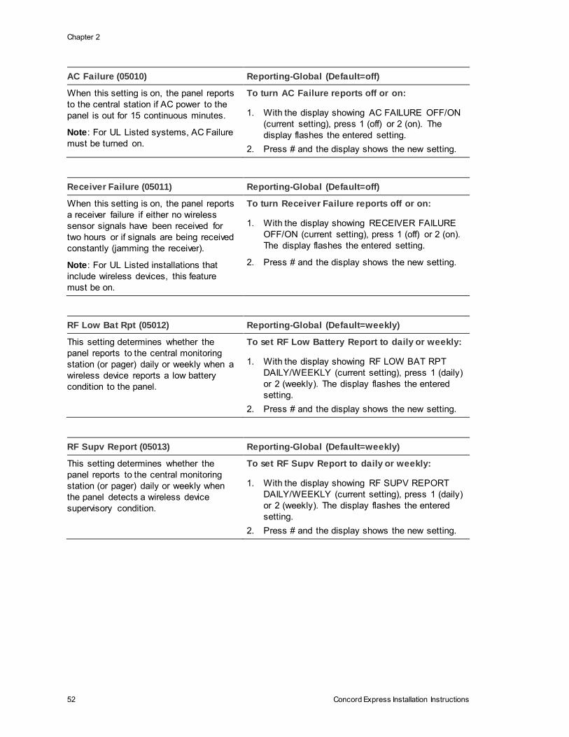
Chapter 2
52 Concord Express Installation Instructions
AC Failure (05010) Reporting-Global (Default=off)
When this setting is on, the panel reports
to the central station if AC power to the
panel is out for 15 continuous minutes.
Note: For UL Listed systems, AC Failure
must be turned on.
To turn AC Failure reports off or on:
1. With the display showing AC FAILURE OFF/ON
(current setting), press 1 (off) or 2 (on). The
display flashes the entered setting.
2. Press # and the display shows the new setting.
Receiver Failure (05011) Reporting-Global (Default=off)
When this setting is on, the panel reports
a receiver failure if either no wireless
sensor signals have been received for
two hours or if signals are being received
constantly (jamming the receiver).
Note: For UL Listed installations that
include wireless devices, this feature
must be on.
To turn Receiver Failure reports off or on:
1. With the display showing RECEIVER FAILURE
OFF/ON (current setting), press 1 (off) or 2 (on).
The display flashes the entered setting.
2. Press # and the display shows the new setting.
RF Low Bat Rpt (05012) Reporting-Global (Default=weekly)
This setting determines whether the
panel reports to the central monitoring
station (or pager) daily or weekly when a
wireless device reports a low battery
condition to the panel.
To set RF Low Battery Report to daily or weekly:
1. With the display showing RF LOW BAT RPT
DAILY/WEEKLY (current setting), press 1 (daily)
or 2 (weekly). The display flashes the entered
setting.
2. Press # and the display shows the new setting.
RF Supv Report (05013) Reporting-Global (Default=weekly)
This setting determines whether the
panel reports to the central monitoring
station (or pager) daily or weekly when
the panel detects a wireless device
supervisory condition.
To set RF Supv Report to daily or weekly:
1. With the display showing RF SUPV REPORT
DAILY/WEEKLY (current setting), press 1 (daily)
or 2 (weekly). The display flashes the entered
setting.
2. Press # and the display shows the new setting.
Chapter 2
Concord Express Installation Instructions 53
Swinger Limit (05014) Reporting-Global (Default=1)
This setting determines the maximum number of
times a sensor or zone can go into alarm (during
a single arming period) before the panel
automatically bypasses that sensor or zone. This
feature only applies to sensors in groups 00-20,
29, or 34.
When set to 1, the panel automatically bypasses
a sensor or zone after it causes an alarm. When
set to 2, the panel waits until a sensor or zone
has caused a second alarm (during the same
arming period) before bypassing it. At either
setting, the automatic bypass is logged into the
event buffer.
A bypassed zone or sensor will be cleared
(automatically “unbypassed”) if the system
receives no further activations from that sensor
or zone over the next 48-50 hours.
Changing the arming level also clears all
automatically bypassed sensors and zones and
resets the Swinger Limit count on all sensors and
zones.
To set the Swinger Limit:
1. With the display showing SWINGER LIMIT
n (current setting), press 1 or 2. The display
flashes the entered setting.
2. Press # and the display shows the new
setting.
The following describes how to program the settings that appear under
REPORTING—PARTITION 1.
Opening Reports (0510) Reporting-Partition 1 (Default=off)
This setting determines whether or not
the panel sends an opening report to the
central station (or pager) after disarming
the system.
Note: To use this feature, the
Open/Close Reports settings under the
PHONES—CS PHONE 1-2 and/or
PHONES—PAGER PHONE 1-3 menus
must be turned on for the specific CS
Phone or Pager Phone number.
To turn Opening Reports off or on:
1. With the display showing OPENING REPORTS
OFF/ON (current setting), press 1 (off) or 2 (on).
The display flashes the entered setting.
2. Press # and the display shows the new setting.
Chapter 2
54 Concord Express Installation Instructions
Closing Reports (0511) Reporting-Partition 1 (Default=off)
This setting determines whether or not
the panel sends a closing report to the
central station (or pager) after arming the
system.
Note: To use this feature, the
Open/Close Reports settings under the
PHONES—CS PHONE 1-2 and/or
PHONES—PAGER PHONE 1-3 menus
must be turned on for the specific CS
Phone or Pager Phone number..
To turn Closing Reports off or on:
1. With the display showing CLOSING REPORTS
OFF/ON (current setting), press 1 (off) or 2 (on).
The display flashes the entered setting.
2. Press # and the display shows the new setting.
Recent Closings (0512) Reporting-Partition 1 (Default=on)
This setting determines whether or not
the panel sends a recent closing report to
the central station (or a pager) if an alarm
occurs within two minutes after the exit
delay time expires. Such a report is used
to identify a possible exit fault.
To turn Recent Closings off or on:
1. With the display showing RECENT CLOSINGS
OFF/ON (current setting), press 1 (off) or 2 (on).
The display flashes the entered setting.
2. Press # and the display shows the new setting.
No Activity (0513) Reporting-Partition 1 (Default=off)
This setting determines whether or not
the panel sends a no activity report to the
central station (or pager) if there is no
system activity within a preset time
period.
To turn No Activity reports off or on:
1. With the display showing NO ACTIVITY OFF/ON
(current setting), press 1 (off) or 2 (on). The
display flashes the entered setting.
2. Press # and the display shows the new setting.
Duress Option (0514) Reporting-Partition 1 (Default=off)
This setting determines whether or not the
system can be controlled using a programmed
duress code.
Caution: Because using duress codes often
results in false alarms due to code entry errors, it
is strongly recommended not to program any
duress codes. If a duress code is absolutely
necessary, their use with an Interrogator is highly
recommended to reduce false alarms and
accidental dispatches.
To turn Duress Option off or on:
1. With the display showing DURESS
OFF/ON (current setting), press 1 (off) or 2
(on). The display flashes the entered
setting.
2. Press # and display shows the new setting.
Chapter 2
Concord Express Installation Instructions 55
Force Armed (0515) Reporting-Partition 1 (Default=off)
This setting determines whether or not the panel
reports to the central monitoring station when a
user force arms the system.
Force Armed occurs if the user presses bypass
when arming the system with open
sensors/zones protesting.
Note: Auto Force Armed always reports to the
central monitoring station. Auto Force Armed
occurs if the user does not press bypass when
arming the system with open sensors/zones
protesting and the siren time expires.
For UL Listed systems, Force Armed must be
turned off.
To turn Force Armed off or on:
1. With the display showing FORCE ARMED
OFF/ON (current setting), press 1 (off) or 2
(on). The display flashes the entered
setting.
2. Press # and the display shows the new
setting.
Alarm Verify (0516) Reporting-Partition 1 (Default=off)
This setting determines whether the
panel reports to the central monitoring
station after a single sensor/zone trip (off)
or waits for a second trip before reporting
(on). The second trip must be a different
sensor and occur within 4 minutes of the
first trip.
This setting affects sensors/zones
learned into groups 10 through 20. If
Alarm Verify is set to on, group 18
responds the same as group 17. See
“Appendix A, Table A.3: Sensor Group
Characteristics.”
Note: For UL Listed systems, Alarm
Verify must be turned off.
To turn Alarm Verify off or on:
1. With the display showing ALARM VERIFY
OFF/ON (current setting), press 1 (off) or 2 (on).
The display flashes the entered setting.
2. Press É and the display shows the new setting.
System Tamper (0517) Reporting-Partition 1
(Default=off)
This setting determines the following:
• Whether or not the armed system goes into alarm if
several incorrect access codes (40 consecutive keystrokes) are entered.
• Whether or not the panel reports to the central station if a
bus device stops communicating with the panel.
• Whether or not the panel reports to the central station if an RF sensor (non fire) is tampered with. Tamper on fire
sensors will always be reported to the central station.
Note: For UL Listed systems, System Tamper must be turned
on.
To change the System Tamper
setting:
1. With the display showing
SYSTEM TAMPER OFF/ON
(current setting), press 1 (off)
or 2 (on). The display flashes
the entered setting.
2. Press # and the display
shows the new setting.
Chapter 2
56 Concord Express Installation Instructions
Siren Options Menu
The SIREN OPTIONS menu lets you set up siren operation and supervision. The
following describes how to program the siren option settings that appear under
GLOBAL.
Immediate Trouble Beeps (0600) Siren Options-Global (Default=off)
This setting determines whether the panel activates
trouble beeps immediately (on) once a wireless
device supervisory condition is detected, or only if
the condition exists at panel supervisory time (off).
Refer to TIMERS—GLOBAL—SUPERVISORY
TIME.
Note: For UL Listed systems, this feature must be
on.
To turn Immediate Trouble Beeps off or on:
1. With the display showing IMMEDIATE
BEEPS OFF/ON (current setting), press 1
(off) or 2 (on). The display flashes the
entered setting.
2. Press # and the display shows the new
setting.
Disable Trouble Beeps (0601) Siren Options-Global (Default=off)
This setting determines whether or not the
panel activates trouble beeps when a wireless
device supervisory condition is detected.
Note: For UL Listed systems, this feature must
be off.
To turn Disable Trouble Beeps off or on:
1. With the display showing DISABLE TR
BEEPS OFF/ON (current setting), press 1
(off) or 2 (on). The display flashes the
entered setting.
2. Press # and the display shows the new
setting.
UL 98 Options (0602) Siren Options-Global (Default=off)
This setting determines whether or not the
panel complies with UL 98 requirements (4-
hour trouble beep restart, 4-hour backup battery
test, 2-hour supervisory time period for sensor
group 26—Fire).
Note: For UL Listed systems, this feature must
be on.
To turn UL 98 Options off or on:
1. With the display showing UL 98 OPTIONS
OFF/ON (current setting), press 1 (off) or 2
(on). The display flashes the entered setting.
2. Press # and the display shows the new
setting.
The following describes how to program the settings that appear under SIREN
OPTIONS—PARTITION 1.
Chapter 2
Concord Express Installation Instructions 57
Siren Verify (0610) Siren Options-Partition 1 (Default=off)
This setting determines whether or not the
panel monitors sirens connected to panel
terminal 7 (OUT1/+12V).
When this feature is on, sirens connected to
panel terminals 3 (GND) and 7 (OUT1/+12V)
require a 2k end-of-line resistor. Refer to
“Installing the System—Connecting Sirens” for
complete details.
Note: For UL Listed systems, this feature must
be on.
To turn Siren Verify off or on:
1. With the display showing SIREN VERIFY
OFF/ON (current setting), press 1 (off) or 2
(on). The display flashes the entered setting.
2. Press # and the display shows the new
setting.
Sensors Menu
Note: If 2-wire smoke detectors are connected to hardwire zone input 6, the Two-
wire Smoke setting must be turned on before entering the LEARN SENSORS
menu. See ONBOARD OPTIONS—INPUTS.
The SENSORS menu gives you access to the following:
• LEARN SENSORS—lets you learn hardwire zones and wireless sensors into
panel memory and assign zones/sensors to specific partitions.
• SENSOR TEXT—lets you program sensor text for zone/sensor identification.
• DELETE SENSORS—lets you delete zones/sensors from panel memory.
• EDIT SENSORS—lets you view and/or change sensor/zone group
assignment, view sensor number and text assignments of learned
sensors/zones, identify whether zone is wireless or hardwire, and indicates
sensor/zone/touchpad input N/C or N/O configuration.
The following describes how to program the sensor settings that appear under
LEARN SENSORS.
Chapter 2
58 Concord Express Installation Instructions
Learn Sensors (070) Sensors (Default=none)
The following describes how to learn
hardwire zones and wireless devices
into panel memory.
The panel comes with six factory
programmed onboard hardwire
zones. The factory programmed
setting are listed below:
• Zone 1: 10-Entry/Exit
• Zone 2: 17-Instant Interior Follower
• Zone 3: 13-Instant Perimeter
• Zone 4: 13-Instant Perimeter
• Zone 5: 13-Instant Perimeter
• Zone 6: 13-Instant Perimeter
Note: Clearing panel memory also
clears all factory programmed
zones.Install an end-of-line resistor
on all unused, factory programmed,
onboard panel zones
OR
Delete the unused zone from panel
memory (see “Accessory Modules
Menu” on page 60).
To Learn Sensors into panel memory:
1. With the display showing SENSORS, press # and the
display shows LEARN SENSORS.
2. Press # and the display shows SENSOR GROUP 0.
3. Enter the desired 2-digit sensor group + # (see
Appendix A for a description of all sensor group
characteristics). The display shows TRIP SENSOR nn,
where nn is the displayed (next available) sensor
number.
4. To change the displayed sensor number, enter the
desired 2-digit sensor number + #.
5. With the desired sensor number displayed, trip the
sensor or zone as follows:
• Hardwire Zones—trip the zone into the alarm state.
• Wireless Sensors—follow the instructions included with each sensor. Wireless Door/Window Sensors with External
Contacts—place the external contact in the alarm condition, then activate the sensor tamper switch.
• Handheld Wireless Touchpads—press and hold the
BYPASS button until the touchpad LED flashes.
• Keychain Touchpads—press and hold the LOCK and UNLOCK buttons together until the touchpad LED
flashes.
• ELM Keychain Touchpads—a.) Press and release the UNLOCK button twice quickly, then press and hold until
the LED flashes three times. b.) Press and release the UNLOCK button once quickly, then press and hold until the LED flashes two times. c.) Press and hold the
UNLOCK button until the LED flashes once.
6. Continue tripping sensors to learn them into the
selected sensor group. To stop learning sensors into a
group, press Ç twice and start again from step 1
(LEARN SENSORS) to learn sensors into another
group (or use the EDIT SENSORS menu to change
group assignment after learning the sensor/zone).
Chapter 2
Concord Express Installation Instructions 59
Sensor Text (071) Sensors (Default=none)
Use the following guidelines for programming
text to identify zone/sensor locations.
• There are 16 character/word locations or
“Item Numbers” for each zone/sensor name. Item numbers for each character/word appear in “Appendix A,
Table A4.”
• If a desired word does not appear in the list, create it using characters (custom text).
• When using words, spaces between them appear automatically. When creating words using characters, you must reserve an item
number for a “space” after creating the word.
• Each character or word uses up one item
number. For example, a word from the list counts as one item number. A created word, such as BOY’S counts as six item
numbers, 4 letters, 1 apostrophe, and 1 space.
• Plan ahead before programming sensor
text. You may need to abbreviate words you create to avoid running out of item numbers.
To program Sensor Text:
1. With the display showing LEARN
SENSORS, press B until the display shows
SENSOR TEXT.
2. Press # and the display shows TEXT FOR
SN 01.
3. Press # and the display shows SN 01 ITEM
00 000 -. Where ITEM 00 is the first
character/word location and 000 is the 3-
digit character/word number.
4. Enter the 3-digit number of the desired
character/word or scroll through the
numbers by pressing B (forward) or by
pressing A (backward). If you make a
mistake, simply enter the correct 3-digit
number or continue scrolling through
choices.
5. Press # to accept the displayed choice and
the display shows SN 01 ITEM 01 000 -.
6. Repeat steps 4 and 5 as needed to
complete the zone/sensor name.
7. Press * after entering the last 3-digit
character/word number. The display shows
the complete text name. For example, TEXT
FOR SN 01 FRONT ENTRY DOOR.
Delete Sensors (072) Sensors (Default=none)
The following describes how to remove
hardwire zone and wireless sensor
numbers from panel memory.
Note: Deleting sensors does not delete
sensor text associated with the deleted
sensor number. To delete sensor text,
enter the SENSOR TEXT menu and
enter 000 (nulls) for each item number.
To Delete Sensors from panel memory:
1. With the display showing LEARN SENSORS,
press B until the display shows DELETE
SENSORS.
2. Press # and the display shows DELETE SENSOR
nn (lowest zone/sensor number in panel memory).
3. Press # to delete the displayed sensor or enter the
desired sensor number, then press #. The display
flashes the entered number, then stops and shows
DELETE SENSOR NN DONE.
4. Repeat steps 2 and 3 until all desired sensors are
deleted.

Chapter 2
60 Concord Express Installation Instructions
Edit Sensors (073) Sensors (Default=none)
This menu lets you view the assignments for
each learned zone/sensor. For example, the
display shows: S01 P1 G13 NC HW BACK DOOR.
where S01 = zone/sensor number,
P1 = partition 1,
G13 = sensor group 13,
NC = normally closed,
HW = hardwired,
and BACK DOOR is the programmed text
name.
You can also change the zone/sensor group
assignment to eliminate the need to delete and
relearn the zone/sensor.
To Edit Sensors:
1. With the display showing LEARN
SENSORS, press B until the display shows
EDIT SENSORS.
2. Press # and the display shows the lowest
sensor number zone/sensor assignments.
3. Press A or B to scroll through all learned
zone/sensor number assignments.
4. When the desired zone/sensor is displayed
press #. The display shows SENSOR
GROUP nn (current group assignment).
5. Enter the desired group number, then press
#. The display shows the new group
assignment.
Accessory Modules Menu
The ACCESSORY MODULES menu gives you access to the following:
• BUS DEVICES—this menu lets you read bus device unit numbers, assign
bus devices to a partition, and set other features associated with a specific
bus device.
Note: Most settings under ACCESSORY MODULES—BUS DEVICES have no shortcut
numbers.
• SNAPCARD—this menu lets you set the configuration number for each
SnapCard output.
The following describes how to program the settings that appear under
ACCESSORY MODULES—BUS DEVICES.
Chapter 2
Concord Express Installation Instructions 61
Unit-ID (0800 thru 0803) Acc. Modules-Bus Devices (Default=none)
This menu lets you identify all
connected bus devices, each device
address, unit ID number, and other
configurations based on a specific
device. You can also delete learned
bus device addresses.
Note: To help identify bus devices,
the 8-digit unit ID number is also
located on a label on each SuperBus
2000 device.
To identify bus device Unit and ID:
1. With the display showing BUS DEVICES, press #. The
display shows the bus device unit number and the 8-digit
unit ID number. For example, UNIT - ID 0—02110185.
Where 0 is the bus device unit number and 02110185 is
the unit ID number.
2. Press A or B to identify all other bus device unit numbers
(0-3) and identification numbers.
To delete learned bus device unit numbers:
1. With the display showing BUS DEVICES, press #. The
display shows the bus device set to unit number 0.
2. Press A or B until the bus device unit number you want
to delete is displayed.
3. Press D. The display changes the unit number to NONE.
Device ID Acc. Modules-Bus Devices (Default=none)
This menu lets you change a
bus device ID number when
replacing a defective bus
device.
To change a Device ID:
1. With the display showing the desired device, press # twice. The
display shows DEVICE ID (current ID).
2. Enter the ID of the new bus device. The display flashes the
entered selection. Press # and the display shows the new
setting.
3. Exit programming mode.
4. Remove AC and battery power from the panel.
5. Replace the defective bus device with the new one.
6. Apply AC and battery power to the panel.
Status Beeps Acc. Modules-Bus Devices (Default=on)
This setting determines whether or not the
selected touchpad sounds status beeps. Each
touchpad can be set individually. This feature is
usually turned off if a touchpad is located in or
near bedrooms to avoid disturbing persons
sleeping.
Note: For UL Listed systems, Status Beeps must
be turned on.
To turn touchpad Status Beeps on or off:
1. With the display showing the desired
touchpad, press # then B once. The display
shows TOUCHPAD OPTIONS.
2. Press # and the display shows STATUS
BEEPS OFF/ON (current setting).
3. Press 1 (off) or 2 (on) to select the desired
setting. The display flashes the entered
selection. Press # and the display shows the
new setting.

Chapter 2
62 Concord Express Installation Instructions
Key Beeps Acc. Modules-Bus Devices (Default=on)
This setting determines whether or not selected
touchpads sound beeps when their buttons are
pressed. This feature is usually turned off if a
touchpad is located in or near bedrooms to avoid
disturbing persons sleeping.
To turn Key Beeps on or off:
1. With the display showing the desired
touchpad, press # + B + # + B. The display
shows KEY BEEPS OFF/ON (current setting).
2. Press 1 (off) or 2 (on) to select the desired
setting. The display flashes the entered
selection. Press # and the display shows the
new setting.
Output 1, 2, 3, 4 (081000-output 1) (081010-
output 2) (081020-output 3) (081030-output 4)
Acc. Modules-SnapCards (Defaults: Output
1=01400, Output 2=00410, Output 3=00903,
Output 4=01003)
This setting lets you assign the 5-digit
configuration number for each SnapCard relay
output that determines which system event
activates the output and the duration or time the
output is activated.
The first three digits represent the trigger number
of an event such as an alarm, open sensor, or
arming the system.
The last two digits represent how the output
responds such as momentary, sustained (or
latched), or for a preset time.
Tables A6-A10 in “Appendix A” identify system
event trigger and response numbers.
To assign configuration numbers to
SnapCard Relay outputs:
1. With the display showing SNAPCARDS, press
#. The display shows OUTPUT
PROGRAMMING.
2. Press # again and the display shows
OUTPUT 1.
3. Press A or B to select the desired output (1-
4), then press #. The display shows OUTPUT
n (current setting).
4. Enter the desired 5-digit configuration
number for this output. The display flashes
the entered number. Press # and the display
shows the new setting.
Onboard Options Menu
The ONBOARD OPTIONS menu lets you set up the following built-in options:
INPUTS—this menu lets you set panel zone input 6 for 2-wire smoke operation
and turn the smoke verification feature off/on.
OUTPUTS—this menu lets you assign the two built-in panel outputs to partitions
and set their configuration numbers.
The following describes how to program the settings that appear under
ONBOARD OPTIONS—INPUTS.
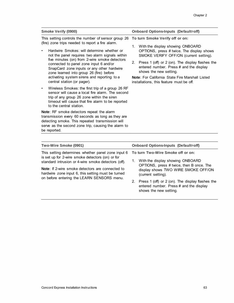
Chapter 2
Concord Express Installation Instructions 63
Smoke Verify (0900) Onboard Options-Inputs (Default=off)
This setting controls the number of sensor group 26
(fire) zone trips needed to report a fire alarm.
• Hardwire Smokes: will determine whether or
not the panel requires two alarm signals within five minutes (on) from 2-wire smoke detectors connected to panel zone input 6 and/or
SnapCard zone inputs or any other hardwire zone learned into group 26 (fire) before activating system sirens and reporting to a
central station (or pager).
• Wireless Smokes: the first trip of a group 26 RF sensor will cause a local fire alarm. The second
trip of any group 26 zone within the siren timeout will cause that fire alarm to be reported to the central station.
Note: RF smoke detectors repeat the alarm
transmission every 60 seconds as long as they are
detecting smoke. This repeated transmission will
serve as the second zone trip, causing the alarm to
be reported.
To turn Smoke Verify off or on:
1. With the display showing ONBOARD
OPTIONS, press # twice. The display shows
SMOKE VERIFY OFF/ON (current setting).
2. Press 1 (off) or 2 (on). The display flashes the
entered number. Press # and the display
shows the new setting.
Note: For California State Fire Marshall Listed
installations, this feature must be off.
Two-Wire Smoke (0901) Onboard Options-Inputs (Default=off)
This setting determines whether panel zone input 6
is set up for 2-wire smoke detectors (on) or for
standard intrusion or 4-wire smoke detectors (off).
Note: If 2-wire smoke detectors are connected to
hardwire zone input 6, this setting must be turned
on before entering the LEARN SENSORS menu.
To turn Two-Wire Smoke off or on:
1. With the display showing ONBOARD
OPTIONS, press # twice, then B once. The
display shows TWO WIRE SMOKE OFF/ON
(current setting).
2. Press 1 (off) or 2 (on). The display flashes the
entered number. Press # and the display
shows the new setting.
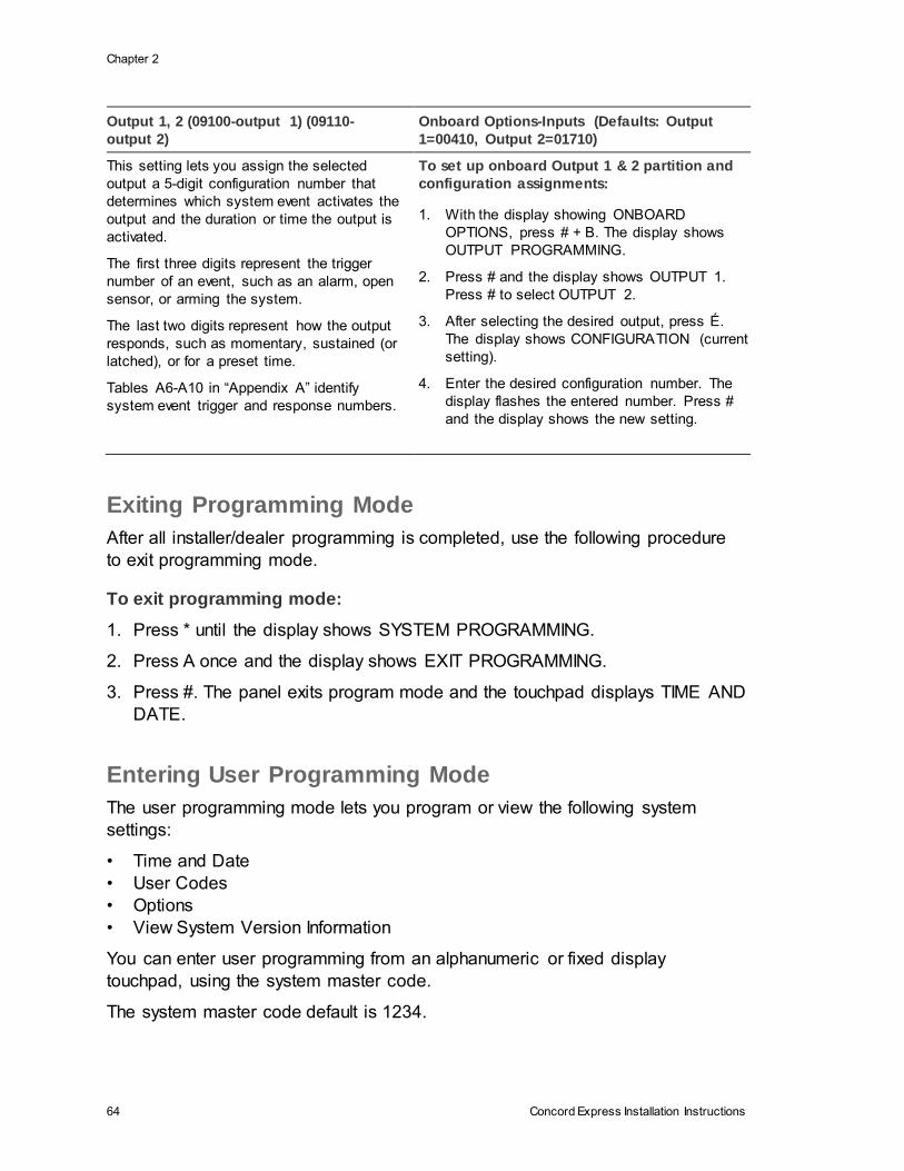
Chapter 2
64 Concord Express Installation Instructions
Output 1, 2 (09100-output 1) (09110-
output 2)
Onboard Options-Inputs (Defaults: Output
1=00410, Output 2=01710)
This setting lets you assign the selected
output a 5-digit configuration number that
determines which system event activates the
output and the duration or time the output is
activated.
The first three digits represent the trigger
number of an event, such as an alarm, open
sensor, or arming the system.
The last two digits represent how the output
responds, such as momentary, sustained (or
latched), or for a preset time.
Tables A6-A10 in “Appendix A” identify
system event trigger and response numbers.
To set up onboard Output 1 & 2 partition and
configuration assignments:
1. With the display showing ONBOARD
OPTIONS, press # + B. The display shows
OUTPUT PROGRAMMING.
2. Press # and the display shows OUTPUT 1.
Press # to select OUTPUT 2.
3. After selecting the desired output, press É.
The display shows CONFIGURATION (current
setting).
4. Enter the desired configuration number. The
display flashes the entered number. Press #
and the display shows the new setting.
Exiting Programming Mode
After all installer/dealer programming is completed, use the following procedure
to exit programming mode.
To exit programming mode:
1. Press * until the display shows SYSTEM PROGRAMMING.
2. Press A once and the display shows EXIT PROGRAMMING.
3. Press #. The panel exits program mode and the touchpad displays TIME AND
DATE.
Entering User Programming Mode
The user programming mode lets you program or view the following system
settings:
• Time and Date
• User Codes
• Options
• View System Version Information
You can enter user programming from an alphanumeric or fixed display
touchpad, using the system master code.
The system master code default is 1234.

Chapter 2
Concord Express Installation Instructions 65
To enter user-programming mode:
Press 9 + CODE. The display shows TIME AND DATE. Press
Time and Date Menu
The TIME AND DATE menu lets you set the panel clock and calendar.
Alphanumeric touchpads display the time and date whenever the system is
disarmed. Setting the time and date is important for accurate tracking of system
events stored in the event buffer. The panel uses a global clock and calendar for
time and date.
The following describes how to set the panel time and date.
Time (00) Time and Date (Default=00:00)
This setting lets you adjust the
panel clock to the correct time. The
panel uses a 24-hour clock,
eliminating the need to designate
A.M. or P.M. For example, to set the
time to 4:17 P.M., enter 1617.
To set the Time:
1. With the display showing TIME AND DATE, press # and
the display shows TIME hh:mm AM/PM (current time).
2. Enter the correct time (0000 - 2359). The display flashes
the entered time. Press # and the display shows the new
time.
Date (01) Time and Date (Default=01/01/00)
This setting lets you adjust the
panel calendar to the correct
month, day, and year.
To set the Date:
1. With the display showing TIME AND DATE, press # then
B and the display shows DATE nn/nn/nn (current date).
2. Enter the correct month (01 - 12), day (01 - 31), and year
(00 - 99). For example, enter 090100 for September 1,
2000. The display flashes the entered date. Press # and
the display shows the new date.
User Codes Menu
Important: Each security access code (Installer, Dealer, system Master, or User)
must be unique. Do not use the same combination of numbers for any two codes.
The USER CODES menu lets you program/change regular user access codes
and the system master code.
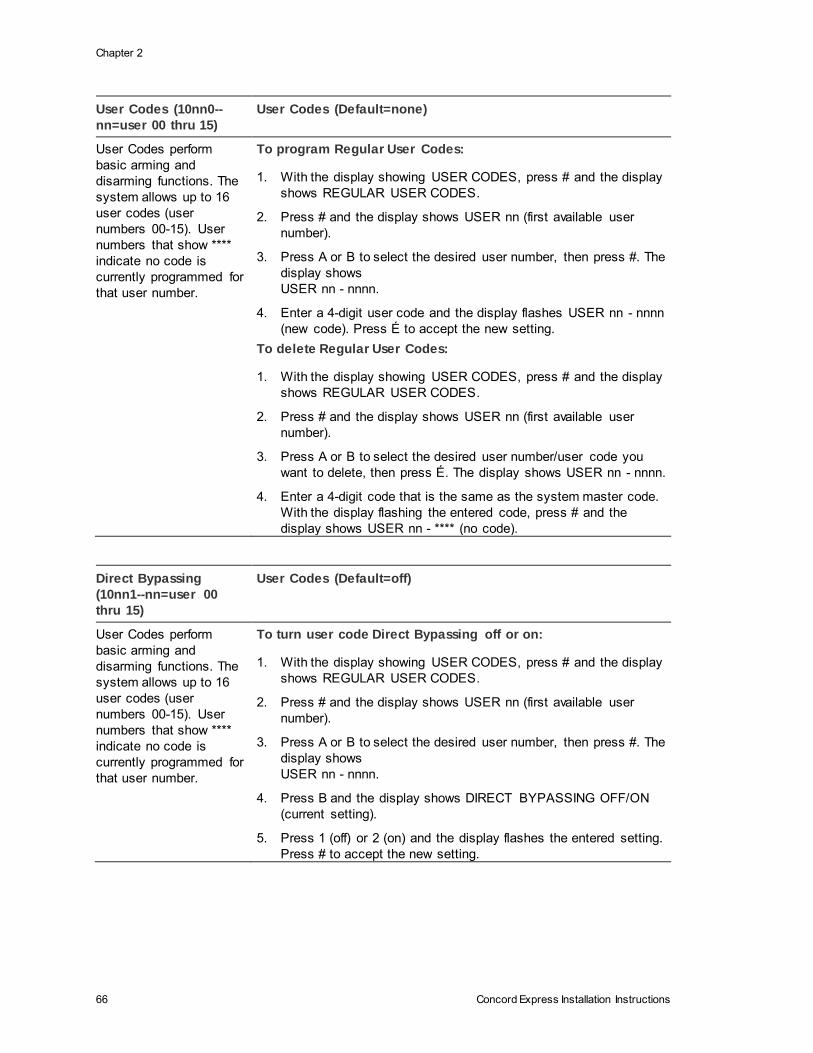
Chapter 2
66 Concord Express Installation Instructions
User Codes (10nn0--
nn=user 00 thru 15)
User Codes (Default=none)
User Codes perform
basic arming and
disarming functions. The
system allows up to 16
user codes (user
numbers 00-15). User
numbers that show ****
indicate no code is
currently programmed for
that user number.
To program Regular User Codes:
1. With the display showing USER CODES, press # and the display
shows REGULAR USER CODES.
2. Press # and the display shows USER nn (first available user
number).
3. Press A or B to select the desired user number, then press #. The
display shows
USER nn - nnnn.
4. Enter a 4-digit user code and the display flashes USER nn - nnnn
(new code). Press É to accept the new setting.
To delete Regular User Codes:
1. With the display showing USER CODES, press # and the display
shows REGULAR USER CODES.
2. Press # and the display shows USER nn (first available user
number).
3. Press A or B to select the desired user number/user code you
want to delete, then press É. The display shows USER nn - nnnn.
4. Enter a 4-digit code that is the same as the system master code.
With the display flashing the entered code, press # and the
display shows USER nn - **** (no code).
Direct Bypassing
(10nn1--nn=user 00
thru 15)
User Codes (Default=off)
User Codes perform
basic arming and
disarming functions. The
system allows up to 16
user codes (user
numbers 00-15). User
numbers that show ****
indicate no code is
currently programmed for
that user number.
To turn user code Direct Bypassing off or on:
1. With the display showing USER CODES, press # and the display
shows REGULAR USER CODES.
2. Press # and the display shows USER nn (first available user
number).
3. Press A or B to select the desired user number, then press #. The
display shows
USER nn - nnnn.
4. Press B and the display shows DIRECT BYPASSING OFF/ON
(current setting).
5. Press 1 (off) or 2 (on) and the display flashes the entered setting.
Press # to accept the new setting.
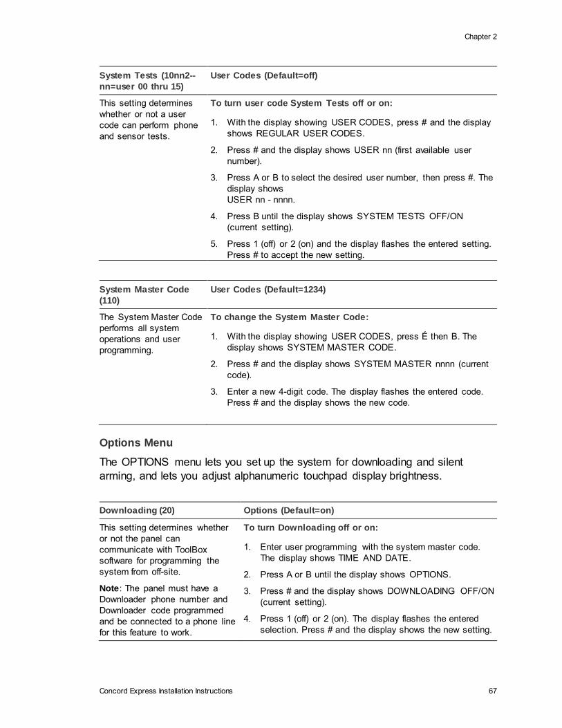
Chapter 2
Concord Express Installation Instructions 67
System Tests (10nn2--
nn=user 00 thru 15)
User Codes (Default=off)
This setting determines
whether or not a user
code can perform phone
and sensor tests.
To turn user code System Tests off or on:
1. With the display showing USER CODES, press # and the display
shows REGULAR USER CODES.
2. Press # and the display shows USER nn (first available user
number).
3. Press A or B to select the desired user number, then press #. The
display shows
USER nn - nnnn.
4. Press B until the display shows SYSTEM TESTS OFF/ON
(current setting).
5. Press 1 (off) or 2 (on) and the display flashes the entered setting.
Press # to accept the new setting.
System Master Code
(110)
User Codes (Default=1234)
The System Master Code
performs all system
operations and user
programming.
To change the System Master Code:
1. With the display showing USER CODES, press É then B. The
display shows SYSTEM MASTER CODE.
2. Press # and the display shows SYSTEM MASTER nnnn (current
code).
3. Enter a new 4-digit code. The display flashes the entered code.
Press # and the display shows the new code.
Options Menu
The OPTIONS menu lets you set up the system for downloading and silent
arming, and lets you adjust alphanumeric touchpad display brightness.
Downloading (20) Options (Default=on)
This setting determines whether
or not the panel can
communicate with ToolBox
software for programming the
system from off-site.
Note: The panel must have a
Downloader phone number and
Downloader code programmed
and be connected to a phone line
for this feature to work.
To turn Downloading off or on:
1. Enter user programming with the system master code.
The display shows TIME AND DATE.
2. Press A or B until the display shows OPTIONS.
3. Press # and the display shows DOWNLOADING OFF/ON
(current setting).
4. Press 1 (off) or 2 (on). The display flashes the entered
selection. Press # and the display shows the new setting.
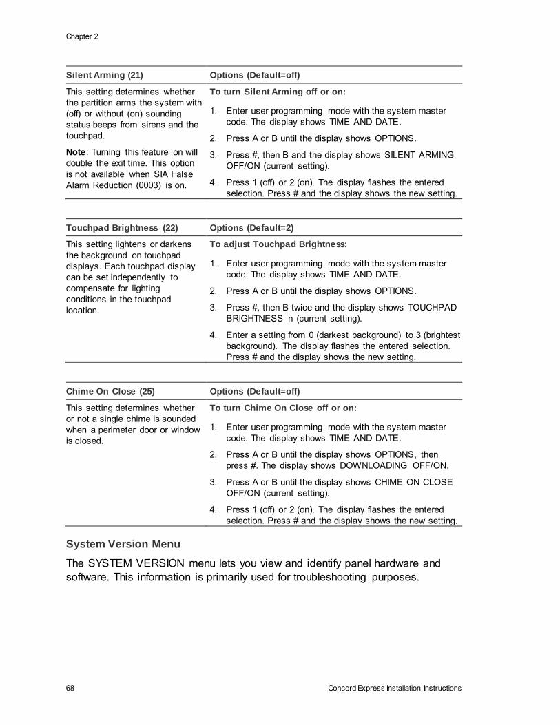
Chapter 2
68 Concord Express Installation Instructions
Silent Arming (21) Options (Default=off)
This setting determines whether
the partition arms the system with
(off) or without (on) sounding
status beeps from sirens and the
touchpad.
Note: Turning this feature on will
double the exit time. This option
is not available when SIA False
Alarm Reduction (0003) is on.
To turn Silent Arming off or on:
1. Enter user programming mode with the system master
code. The display shows TIME AND DATE.
2. Press A or B until the display shows OPTIONS.
3. Press #, then B and the display shows SILENT ARMING
OFF/ON (current setting).
4. Press 1 (off) or 2 (on). The display flashes the entered
selection. Press # and the display shows the new setting.
Touchpad Brightness (22) Options (Default=2)
This setting lightens or darkens
the background on touchpad
displays. Each touchpad display
can be set independently to
compensate for lighting
conditions in the touchpad
location.
To adjust Touchpad Brightness:
1. Enter user programming mode with the system master
code. The display shows TIME AND DATE.
2. Press A or B until the display shows OPTIONS.
3. Press #, then B twice and the display shows TOUCHPAD
BRIGHTNESS n (current setting).
4. Enter a setting from 0 (darkest background) to 3 (brightest
background). The display flashes the entered selection.
Press # and the display shows the new setting.
Chime On Close (25) Options (Default=off)
This setting determines whether
or not a single chime is sounded
when a perimeter door or window
is closed.
To turn Chime On Close off or on:
1. Enter user programming mode with the system master
code. The display shows TIME AND DATE.
2. Press A or B until the display shows OPTIONS, then
press #. The display shows DOWNLOADING OFF/ON.
3. Press A or B until the display shows CHIME ON CLOSE
OFF/ON (current setting).
4. Press 1 (off) or 2 (on). The display flashes the entered
selection. Press # and the display shows the new setting.
System Version Menu
The SYSTEM VERSION menu lets you view and identify panel hardware and
software. This information is primarily used for troubleshooting purposes.
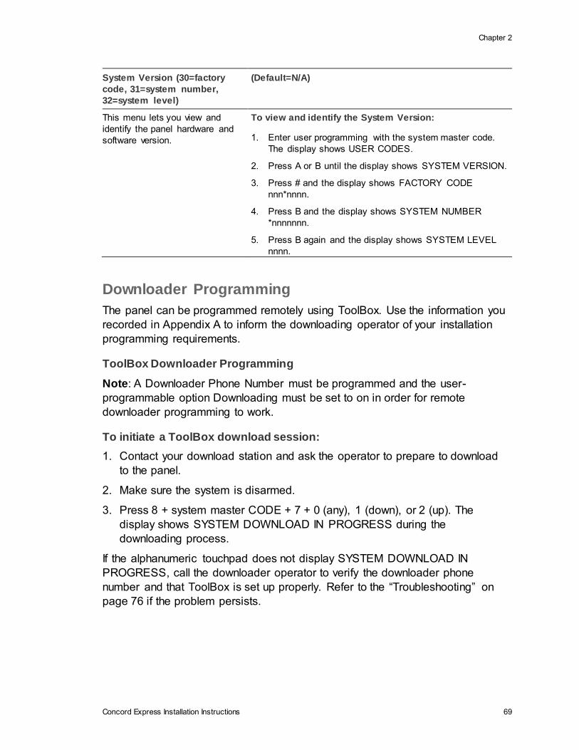
Chapter 2
Concord Express Installation Instructions 69
System Version (30=factory
code, 31=system number,
32=system level)
(Default=N/A)
This menu lets you view and
identify the panel hardware and
software version.
To view and identify the System Version:
1. Enter user programming with the system master code.
The display shows USER CODES.
2. Press A or B until the display shows SYSTEM VERSION.
3. Press # and the display shows FACTORY CODE
nnn*nnnn.
4. Press B and the display shows SYSTEM NUMBER
*nnnnnnn.
5. Press B again and the display shows SYSTEM LEVEL
nnnn.
Downloader Programming
The panel can be programmed remotely using ToolBox. Use the information you
recorded in Appendix A to inform the downloading operator of your installation
programming requirements.
ToolBox Downloader Programming
Note: A Downloader Phone Number must be programmed and the user-
programmable option Downloading must be set to on in order for remote
downloader programming to work.
To initiate a ToolBox download session:
1. Contact your download station and ask the operator to prepare to download
to the panel.
2. Make sure the system is disarmed.
3. Press 8 + system master CODE + 7 + 0 (any), 1 (down), or 2 (up). The
display shows SYSTEM DOWNLOAD IN PROGRESS during the
downloading process.
If the alphanumeric touchpad does not display SYSTEM DOWNLOAD IN
PROGRESS, call the downloader operator to verify the downloader phone
number and that ToolBox is set up properly. Refer to the “Troubleshooting” on
page 76 if the problem persists.

Concord Express Installation Instructions 71
Chapter 3 Testing/Troubleshooting
This section describes the following subjects:
• Basic System Commands
• Testing Zones/Sensors
• Testing Phone Communication
• Testing Central Station/Pager Communication
You should test the system after installing or servicing and after adding or
removing devices from the system. UL Listed systems should be tested weekly.
Refer to the “Troubleshooting” on page 76 if correct test results are not achieved.
Content
Basic system commands 72
Testing Zones/Sensors 72
Testing Phone Communication 73
Testing Central Station/Pager Communication 74
Testing Outputs/Sirens 74
Changing Fixed Display LCD Touchpad Chime and Trouble Beep Tones 76
Troubleshooting 76
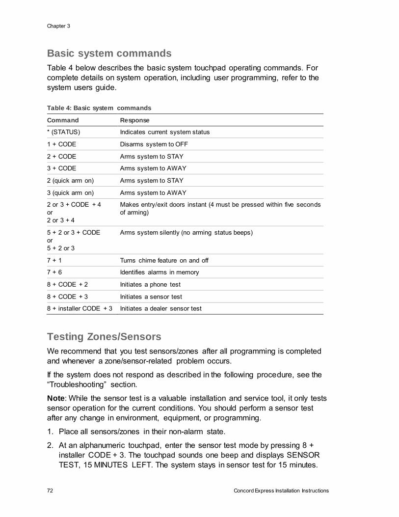
Chapter 3
72 Concord Express Installation Instructions
Basic system commands
Table 4 below describes the basic system touchpad operating commands. For
complete details on system operation, including user programming, refer to the
system users guide.
Table 4: Basic system commands
Command Response
* (STATUS) Indicates current system status
1 + CODE Disarms system to OFF
2 + CODE Arms system to STAY
3 + CODE Arms system to AWAY
2 (quick arm on) Arms system to STAY
3 (quick arm on) Arms system to AWAY
2 or 3 + CODE + 4
or
2 or 3 + 4
Makes entry/exit doors instant (4 must be pressed within five seconds
of arming)
5 + 2 or 3 + CODE
or
5 + 2 or 3
Arms system silently (no arming status beeps)
7 + 1 Turns chime feature on and off
7 + 6 Identifies alarms in memory
8 + CODE + 2 Initiates a phone test
8 + CODE + 3 Initiates a sensor test
8 + installer CODE + 3 Initiates a dealer sensor test
Testing Zones/Sensors
We recommend that you test sensors/zones after all programming is completed
and whenever a zone/sensor-related problem occurs.
If the system does not respond as described in the following procedure, see the
“Troubleshooting” section.
Note: While the sensor test is a valuable installation and service tool, it only tests
sensor operation for the current conditions. You should perform a sensor test
after any change in environment, equipment, or programming.
1. Place all sensors/zones in their non-alarm state.
2. At an alphanumeric touchpad, enter the sensor test mode by pressing 8 +
installer CODE + 3. The touchpad sounds one beep and displays SENSOR
TEST, 15 MINUTES LEFT. The system stays in sensor test for 15 minutes.
Chapter 3
Concord Express Installation Instructions 73
When less than 5 minutes remain, touchpads and interior sirens beep once
every minute. After 15 minutes the panel disarms to OFF automatically.
3. Trip each zone/sensor one at a time. Touchpads (and interior sirens) should
sound one short, high-pitched beep and the display shows the sensor name
(or number if text for that sensor is not programmed) and OK.
Note: If you hear a long, low-pitched beep, proceed to the section “If a
Wireless Sensor Does Not Test.”
4. Press the status button when you think all zones/sensors are tested. The
touchpad displays any untested sensors/zones and touchpad panics. If all
sensors/zones and touchpad panics have been tested, the display shows
SENSOR TEST OK or ZONES ALL TESTED (fixed display touchpads).
5. Test any untested zones/sensors and touchpad panics.
6. If you need more time to complete the sensor test, press 8 + installer CODE +
3 while the system is still in sensor test. This restarts the 15 minutes of test
time.
7. When all sensors/zones and touchpad panics have been tested, press 1 +
installer CODE to exit sensor test.
If a Wireless Sensor Does Not Test
If touchpads display SENSOR FAILURE and sirens sound a long, low-pitched
beep when a zone/sensor is tripped, this indicates wireless sensor signal
strength is below acceptable limits. Distance from the receiver and/or installation
environment are most likely affecting the sensor signal strength.
When possible, locate wireless sensors within 100 feet of the panel. While a
transmitter may have a range of 1,000 feet or more out in the open, the
environment at the installation site can have a significant effect on transmitter
range. Refer to the ““Troubleshooting” on page 76 to resolve the problem.
For wireless sensors that don’t respond, use an RF Sniffer (60-401) test tool to
verify that the sensor is transmitting. Constant beeps from the RF Sniffer indicate
a runaway (faulty) sensor. Remove the sensor battery and replace the sensor.
Testing Phone Communication
Perform a phone test to check the phone communication between the panel and
the central monitoring station.
To perform a phone test:
1. Contact the central monitoring station to inform them that you are testing the
system.
Chapter 3
74 Concord Express Installation Instructions
2. Press 8 + system master CODE + 2. The display shows PHONE TEST and
the touchpad sounds one beep.
When the panel completes the test, the system returns to the previous arming
level automatically.
If the display continues to show PHONE TEST for 1½ minutes or more, enter 1 +
system master CODE and refer to the “Troubleshooting” on page 76.
Testing Central Station/Pager Communication
After performing sensor and phone tests, check that the system is reporting
alarms successfully to the central station (or pager).
To test communication with the central station/pager:
Note: The way information is displayed varies with pager services and may not
match the example to the right. Account numbers with alpha-characters also vary
when displayed, depending on pager service. Account numbers are not
displayed if Streamlining is turned on.
1. Call the central station and tell the operator that you will be testing the
system.
2. Arm the system.
3. Test each of the touchpad and wireless panic buttons and trip at least one
sensor of each type (fire, intrusion, etc.) to verify correct operation.
4. Check pager displays to verify reports are received. Pagers display an event
code, digit sensor number, and the last four digits of the account number.
For example, a pager display of 999 002 7468 indicates the following; 999 =
alarm
condition, 002 = sensor/zone in alarm or user number, and 7468 = last four
digits of account number. Table 5 on page 75 describes pager system event
codes. Table 6 on page 75 describes pager sensor/zone number and user
number report codes
5. When you finish testing the system, call the central monitoring station to verify
that the alarms were received.
Testing Outputs/Sirens
All outputs (Onboard and SnapCard) should be tested to verify configuration
programming.

Chapter 3
Concord Express Installation Instructions 75
To Test Outputs:
1. Contact the central monitoring station to inform them that you are testing the
system.
2. Verify that all wiring at the panel and output devices is correct.
3. Activate the appropriate device to trigger each output as programmed.
4. Verify that each output responds according to the programmed configuration
number. For outputs that trigger sirens, verify that the correct alarm sounds
are produced from these sirens. Table 7 on page 76 describes the system
alarm sounds you should hear for each alarm event.
Contact the central monitoring station when you are finished testing.
Caution: Be sure to contact the central monitoring station before activating
outputs that trigger from an alarm condition.
Table 5: Pager system event codes
Code System event
009 Zone Restoral
111 System Disarmed
118 Trouble Condition Cleared
119 Alarm Canceled
222 System Armed to STAY
333 System Armed to AWAY
555 Phone Test
888 System Trouble Condition
999 System in Alarm
Table 6: Pager codes
Code System event
000 System event not caused by a zone or user
001 - 0024 Sensor/Zone Numbers 1 - 24
600 - 615 Regular User Codes 0 - 15 used
678 System Master Code used
679 Installer Code used
680 Dealer Code used
697 Quick Arm used
698 Keyswitch Sensor used
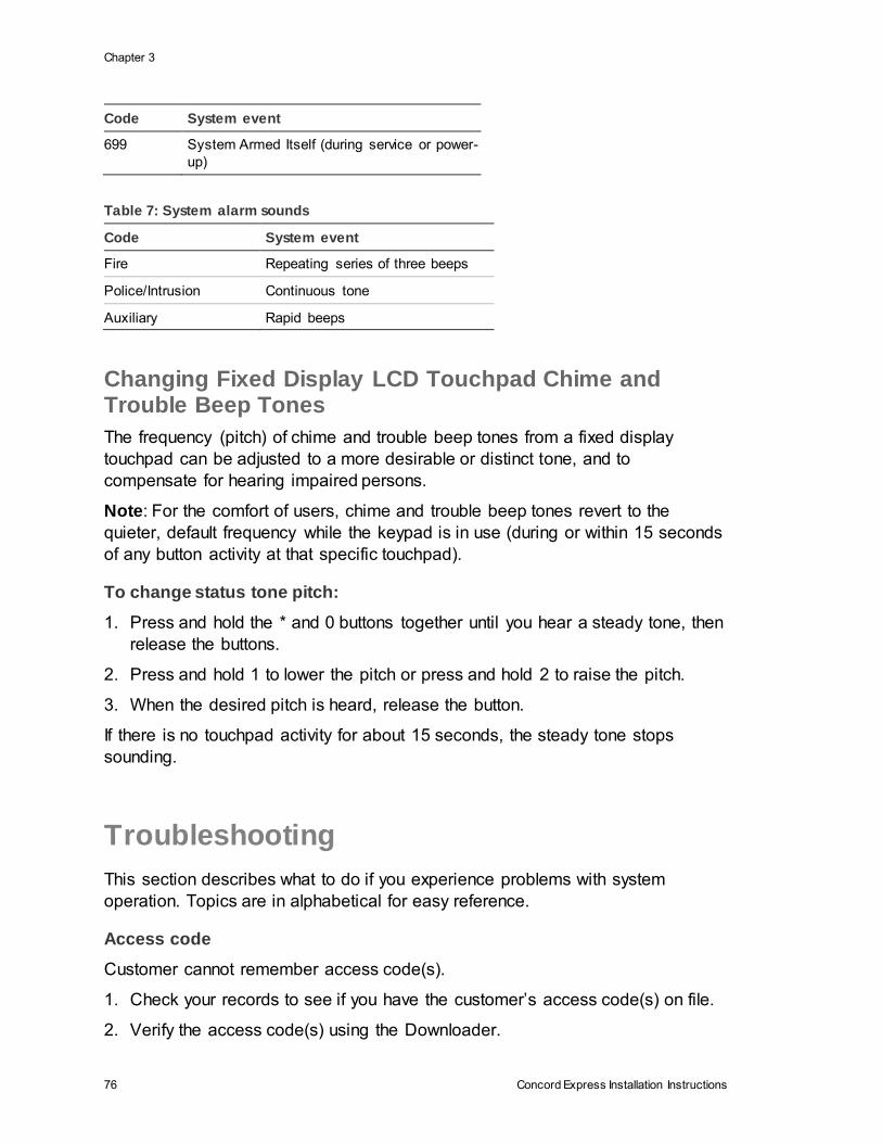
Chapter 3
76 Concord Express Installation Instructions
Code System event
699 System Armed Itself (during service or power-
up)
Table 7: System alarm sounds
Code System event
Fire Repeating series of three beeps
Police/Intrusion Continuous tone
Auxiliary Rapid beeps
Changing Fixed Display LCD Touchpad Chime and Trouble Beep Tones
The frequency (pitch) of chime and trouble beep tones from a fixed display
touchpad can be adjusted to a more desirable or distinct tone, and to
compensate for hearing impaired persons.
Note: For the comfort of users, chime and trouble beep tones revert to the
quieter, default frequency while the keypad is in use (during or within 15 seconds
of any button activity at that specific touchpad).
To change status tone pitch:
1. Press and hold the * and 0 buttons together until you hear a steady tone, then
release the buttons.
2. Press and hold 1 to lower the pitch or press and hold 2 to raise the pitch.
3. When the desired pitch is heard, release the button.
If there is no touchpad activity for about 15 seconds, the steady tone stops
sounding.
Troubleshooting
This section describes what to do if you experience problems with system
operation. Topics are in alphabetical for easy reference.
Access code
Customer cannot remember access code(s).
1. Check your records to see if you have the customer’s access code(s) on file.
2. Verify the access code(s) using the Downloader.
Chapter 3
Concord Express Installation Instructions 77
3. Clear memory and reprogram the panel locally.
Note: Clearing panel memory deletes factory zone programming.
Installer cannot remember install code.
1. Check your records to see if you have the install code on fi le.
2. Verify the install code using the Downloader.
3. Use the Dealer Code to enter program mode and view the installer code.
4. Call Technical Support for assistance.
Installer cannot remember dealer code
1. Check your records to see if you have the dealer code on file.
2. Verify the dealer code using the Downloader.
3. Call Technical Support for assistance.
Alphanumeric Touchpads
Display shows all ************.
• Touchpad is not connected to panel bus terminals or is wired incorrectly.
Check and correct wiring.
Display is blank.
1. Check that panel is powered up.
2. Check for touchpad power and/or bus miswiring, opens, or shorts.
3. Check touchpad brightness setting (see the user programming OPTIONS
menu).
Touchpad buttons don’t beep when pressed.
1. Check for touchpad power and/or bus miswiring, opens, or shorts.
2. Check that key beeps option is set to on (see the ACCESSORY MODULES—
BUS DEVICES menu).
Arming and Disarming
System protests and won’t arm.
1. If arming to level 2, make sure all monitored perimeter doors and windows are
closed.
2. If arming to level 3, make sure all perimeter and interior sensors are closed.
3. Press status for an indication of the problem.
System won’t disarm.
Chapter 3
78 Concord Express Installation Instructions
1. Disarming using incorrect code. Enter correct code.
2. Access code is not programmed or set up in user programming to disarm
system.
3. Wireless touchpad is not learned into system or hardwire touchpad is not
communicating to panel. Check installer programming for learned touchpads.
4. The installer code is being used to disarm the system. The system is
designed not to disarm using the installer code. Use a regular or system
master code to disarm the system.
Bypassing
Touchpad indicates Invalid when you attempt to bypass a sensor.
1. Sensor is already bypassed.
2. Attempting to bypass a 24-hour sensor that cannot be bypassed (group 26
fire sensors).
3. Sensor is not active in the current arming level.
System cancels sensor bypass when you try to arm to level 2 or 3.
• Sensor is being bypassed before arming to 2—STAY or 3—AWAY. Arm to
the desired level before bypassing a sensor.
Central Station/Pager Reporting
Central station/pager is not receiving reports.
1. Check that the premises phone line is working.
2. Perform a phone test.
3. Check that the DB-8 cord is plugged into the RJ-31X/CA-38A jack.
4. Check that the DB-8 cord is wired correctly to the panel.
5. Check for correct phone line wiring between the TELCO block and RJ-
31X/CA-38A jack.
6. Replace faulty RJ-31X/CA-38A jack.
7. Replace faulty DB-8 cord.
8. Verify that central station/pager phone number is programmed into the panel.
Reprogram the phone number and retest, if necessary.
9. Verify that reporting features, such as High Level Rpts and Low Level Rpts,
are set to “on.”
10. Verify that the correct phone format (SIA or CID) is being used.
Chapter 3
Concord Express Installation Instructions 79
11. For pagers, extend the pager delay setting (see the PHONE OPTIONS—
GLOBAL menu in the “Entering programming mode” on page 28.
Downloading/Uploading
Download/upload session fails on a pre-programmed panel.
1. Check all phone troubleshooting Action/Solution steps.
2. Verify Downloader Phone Number matches ToolBox setting.
3. Verify Downloader Code matches ToolBox setting.
4. Verify Dealer Code matches ToolBox setting.
5. Verify panel Account Number matches ToolBox setting.
Download/upload session fails on an unprogrammed panel.
• Check all phone troubleshooting Action/Solution steps.
Hardwire Zones
System doesn’t go into alarm when zone is tripped.
1. System is disarmed. Arm system and then trip the zone.
2. Zone is not learned into panel memory. Enter installer/dealer program mode
and use the LEARN SENSORS menu to add the zone into memory.
Zone reports trouble condition.
1. Check that onboard and SnapCard zone inputs have a 2k-ohm EOL resistor
installed at the last device on the loop (in series for N/C loops or in parallel for
N/O loops).
2. Check for zone wire fault—short circuit on N/C loops, open circuit on N/O
loops.
3. Make sure all devices on zone are in non-alarm state, then enter disarm
command to reset zone.
Panel Power
Panel does not power up. Touchpads don’t display or respond.
1. Check that panel transformer is plugged into an unswitched outlet.
2. Check the AC circuit breaker to be sure the circuit is live.
3. Check that the backup battery is installed correctly and the AC power
transformer is plugged in.
4. Check for proper panel and transformer wiring.
Chapter 3
80 Concord Express Installation Instructions
5. Measure the incoming AC voltage at panel terminals 1 and 2. It should read
about 16.5 VAC.
No incoming AC voltage at panel terminals 1 and 2.
1. Unplug the AC power transformer and disconnect the wires from the
transformer and the panel.
2. Check transformer to panel wire for short or open circuits.
3. Plug in the transformer and check for 16.5 VAC at the transformer
unconnected terminals. If zero (0) volts, replace the transformer.
Touchpad display indicates SYSTEM LOW BATTERY.
1. Check that the backup battery is installed correctly and the AC power
transformer is plugged in.
2. Measure the incoming AC voltage at the panel terminals 1 and 2. It should
read about 16.5 VAC.
3. Remove the backup battery power by disconnecting the red (positive) battery
wire. Check for 11.75 to 13.5 VDC battery charging voltage between panel
terminal 3 (GND) and the disconnected red battery wire. If the charging
voltage is not within range, call Technical Services.
4. Check for 11.75 to 13.5 VDC battery voltage between the backup battery
spade lugs. If the battery voltage is not within this range, replace the battery.
Note: When the panel is running a backup battery test, the reading at the
connected battery can range from 11.2 to 13.5 VDC. The panel automatically
runs a backup battery test under the following conditions: (1) on initial power-
up, (2) during user sensor test, (3) once every minute when backup battery
has failed, (4) once every 24 hours at the programmed STIME (UL 98 Options
off) or once every 4 hours (UL 98 Options on).
With the AC power transformer plugged in, the panel automatically charges
the battery. While the battery is charging for the first time it is normal for the
system to indicate System battery failure. This can take a number of hours
depending on the initial battery charge. Once the battery reaches 12.5 VDC
(full charge as measured while in battery test), the condition clears. If the
trouble condition persists after 24 hours, replace the backup battery.
After you press status, the touchpads flash AC or display AC POWER
FAILURE/AC FAILURE. (Panel continues to operate from backup battery.)
1. Check the AC circuit breaker to be sure the circuit is live.
2. Check for proper panel and transformer wiring.
3. Check that the transformer is plugged into a nonswitched outlet and secured
with the provided screw.
Chapter 3
Concord Express Installation Instructions 81
4. Check that the transformer is supplying AC to the panel. (Transformer internal
fuse may be blown.)
WARNING: Be careful when securing the transformer to an outlet metal cover.
Hold the cover tightly in place. You could receive a serious shock if the metal
outlet cover drops down onto the prongs of the plug while you are securing the
transformer and cover to the outlet box.
Phones
Loss of dial tone at on-site phones after wiring RJ-31X jack or connecting the
DB-8 cord.
1. Wait 2 minutes and try again. The panel may be busy trying to report to the
central station.
2. Disconnect the panel DB-8 cord from the RJ-31 jack. If the phone still doesn’t
work, the system is okay and the problem is in the wiring.
3. Check RJ-31X jack wiring and TELCO block wiring. Replace RJ-31X jack if
necessary.
4. Check DB-8 cord connections at the panel and RJ-31X jack. Replace cord if
necessary.
5. Perform a phone test after troubleshooting the phone line.
Constant dial tone preventing dial-out on premises phones.
• One or more polarity-sensitive phones exist on-site. Reverse the phone wires
connected to the brown and gray wire terminals on the RJ-31X jack.
Sirens
Piezo sirens connected to SnapCard or onboard (panel) outputs 1 and/or 2 don’t
produce any alarm sounds.
1. Check for incorrect wiring between siren and panel; correct where necessary.
2. Output has not been configured (set up) to activate sirens. Enter program
mode and configure output (see ACCESSORY MODULES—BUS
DEVICES—SNAP CARD, or ONBOARD OPTIONS—OUTPUT 1, 2 in the
“Programming” section and the tables in Appendix A).
Wireless Sensor and Touchpad Batteries
System indicates SENSOR/TOUCHPAD NN LOW BATTERY.
• Replace the indicated device battery. Test the sensor/touchpad after
replacing the battery.
Chapter 3
82 Concord Express Installation Instructions
Note: If the sensor/touchpad is not tested after battery replacement, the
system continues to show a low battery condition since that was the last
signal it received from the device. Testing the sensor/touchpad with new
batteries allows the panel to receive a signal with good battery information.
Wireless Sensor Zones
System doesn’t respond (in sensor test or when armed) when sensor is tripped.
1. Verify that panel loop antenna is installed up into antenna housing mounted
on top of panel cabinet.
2. Check that the wireless sensor battery is installed.
3. Check the sensor battery for low voltage. Replace batteries if necessary.
4. Use an RF Sniffer (60-401) to verify that sensor is transmitting.
5. Sensor is not learned into panel memory. Enter installer/dealer program mode
and use the LEARN SENSORS menu to add the sensor into memory.
Sensor reports trouble condition.
1. Sensor tamper switch is tripped—sensor cover is off, not latched securely, or
sensor is not mounted securely. Secure sensor mounting and/or cover, then
trip sensor to clear the condition.
2. Check the sensor battery for low voltage. Replace batteries, if necessary.
Touchpad indicates [SENSOR #] SUPERVISORY.
1. Use an RF Sniffer (60-401) to verify that sensor is transmitting. If sensor is
not transmitting, check battery for low or no voltage and replace.
2. Change mounting position of sensor (from horizontal to vertical or vice versa)
and test sensor several times for consistency.
3. Sensor signal is not reaching panel/receiver because sensor is too far away.
Remove sensor from mounted location and test from other locations. Mount
sensor in area where signal can reach panel/receiver.
Smoke sensor beeps once every minute.
• Sensor batteries are getting low. Replace batteries.
Note: System Sensor smoke sensors (model RF2300) don’t transmit a low
battery signal to the panel/receiver until battery voltage drops to within a
range of 4.7 to 5.4 VDC. The sensor sounds beeps to notify occupants that
the sensor batteries need replacing, but the sensor does not transmit a low
battery signal to the panel until the next supervisory signal (69 minutes later).

Chapter 3
Concord Express Installation Instructions 83
Wireless Touchpads
System doesn’t respond to commands entered from a wireless touchpad.
1. Verify that panel loop antenna is installed up into antenna housing mounted
on top of panel cabinet.
2. Check that touchpad battery is installed.
3. Check the touchpad battery for low voltage. Replace battery, if necessary.
4. Use an RF Sniffer (60-401) to verify that touchpad is transmitting.
5. Touchpad is not learned into panel memory. Enter program mode and learn
touchpad into memory.
Touchpad reports trouble condition.
• Check the touchpad battery for low voltage. Replace battery, if necessary.

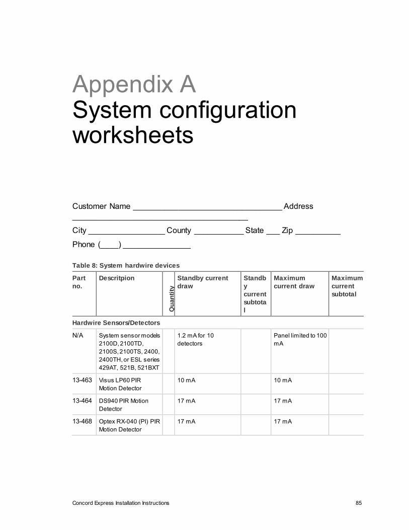
Concord Express Installation Instructions 85
Appendix A System configuration worksheets
Customer Name _________________________________ Address
_______________________________________
City _________________ County ___________ State ___ Zip __________
Phone (____) _______________
Table 8: System hardwire devices
Part
no.
Descritpion
Qu
an
tity
Standby current
draw
Standb
y
current
subtota
l
Maximum
current draw
Maximum
current
subtotal
Hardwire Sensors/Detectors
N/A System sensor models
2100D, 2100TD,
2100S, 2100TS, 2400,
2400TH, or ESL series
429AT, 521B, 521BXT
1.2 mA for 10
detectors
Panel limited to 100
mA
13-463 Visus LP60 PIR
Motion Detector
10 mA 10 mA
13-464 DS940 PIR Motion
Detector
17 mA 17 mA
13-468 Optex RX-040 (PI) PIR
Motion Detector
17 mA 17 mA
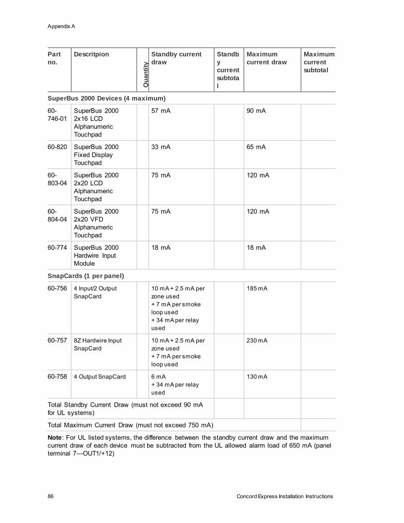
Appendix A
86 Concord Express Installation Instructions
Part
no.
Descritpion
Qu
an
tity
Standby current
draw
Standb
y
current
subtota
l
Maximum
current draw
Maximum
current
subtotal
SuperBus 2000 Devices (4 maximum)
60-
746-01
SuperBus 2000
2x16 LCD
Alphanumeric
Touchpad
57 mA 90 mA
60-820 SuperBus 2000
Fixed Display
Touchpad
33 mA 65 mA
60-
803-04
SuperBus 2000
2x20 LCD
Alphanumeric
Touchpad
75 mA 120 mA
60-
804-04
SuperBus 2000
2x20 VFD
Alphanumeric
Touchpad
75 mA 120 mA
60-774 SuperBus 2000
Hardwire Input
Module
18 mA 18 mA
SnapCards (1 per panel)
60-756 4 Input/2 Output
SnapCard
10 mA + 2.5 mA per
zone used
+ 7 mA per smoke
loop used
+ 34 mA per relay
used
185 mA
60-757 8Z Hardwire Input
SnapCard
10 mA + 2.5 mA per
zone used
+ 7 mA per smoke
loop used
230 mA
60-758 4 Output SnapCard
6 mA
+ 34 mA per relay
used
130 mA
Total Standby Current Draw (must not exceed 90 mA
for UL systems)
Total Maximum Current Draw (must not exceed 750 mA)
Note: For UL listed systems, the difference between the standby current draw and the maximum
current draw of each device must be subtracted from the UL allowed alarm load of 650 mA (panel
terminal 7—OUT1/+12)

Appendix A
Concord Express Installation Instructions 87
Table 9: Zone/sensor assignments
No. Group Zone/sensor text
01
02
03
04
05
06
07
08
09
10
11
12
13
14
15
16
17
18
19
20
21
22
23
24
Table 10: Sensor group characteristics
No. Name Application Alarm Delay
Resto
ral
Su
perv
iso
ry
CS
Rep
ort
s
Ch
ime
Active
levels
00 Fixed Panic
24-hour audible
fixed emergency
buttons.
Police
Instant
X X 1, 2, 3
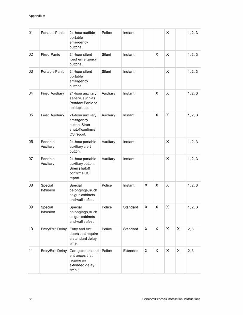
Appendix A
88 Concord Express Installation Instructions
01 Portable Panic
24-hour audible
portable
emergency
buttons.
Police
Instant
X 1, 2, 3
02 Fixed Panic
24-hour silent
fixed emergency
buttons.
Silent
Instant
X X 1, 2, 3
03 Portable Panic
24-hour silent
portable
emergency
buttons.
Silent
Instant
X 1, 2, 3
04 Fixed Auxiliary
24-hour auxiliary
sensor, such as
Pendant Panic or
holdup button.
Auxiliary
Instant
X X 1, 2, 3
05 Fixed Auxiliary
24-hour auxiliary
emergency
button. Siren
shutoff confirms
CS report.
Auxiliary
Instant
X X 1, 2, 3
06 Portable
Auxiliary
24-hour portable
auxiliary alert
button.
Auxiliary Instant X 1, 2, 3
07 Portable
Auxiliary
24-hour portable
auxiliary button.
Siren shutoff
confirms CS
report.
Auxiliary
Instant
X 1, 2, 3
08 Special
Intrusion
Special
belongings, such
as gun cabinets
and wall safes.
Police
Instant
X X X 1, 2, 3
09 Special
Intrusion
Special
belongings, such
as gun cabinets
and wall safes.
Police
Standard
X X X 1, 2, 3
10 Entry/Exit Delay
Entry and exit
doors that require
a standard delay
time.
Police
Standard
X X X X 2, 3
11 Entry/Exit Delay
Garage doors and
entrances that
require an
extended delay
time. *
Police
Extended
X X X X 2, 3

Appendix A
Concord Express Installation Instructions 89
12 Entry/Exit Delay
Driveway gates
and entrances
that require a
twice extended
delay time. *
Police
Twice
Extended
X X X X 2, 3
13 Instant
Perimeter
Exterior doors and
windows.
Police Instant X X X X 2, 3
14 Instant Interior Interior doors. Police Follower X X X 2, 3
15 Instant Interior Interior PIR
motion sensors. *
Police
Follower X X 2, 3
16 Instant Interior Interior doors. Police Follower X X X 3
17 Instant Interior PIR motion
sensors. *
Police Follower X X 3
18 Instant Interior PIR motion
sensors subject to
false alarms. * †
Police Follower
X X 3
19 Delayed Interior
Interior doors that
initiate a delay
before going into
alarm. *
Police
Standard
X X X 3
20 Delayed Interior
PIR motion
sensors that
initiate a delay
before going into
alarm. *
Police
Standard
X X 3
21 Local Instant
Interior
24-hour local
alarm zone
protecting
anything that
opens and closes.
Police
Instant
X X 1, 2, 3
22 Local Delayed
Interior
Same as group
21, plus activation
initiates a delay
before going into
alarm.
Police
Standard
X X 1, 2, 3
23 Local Instant
Auxiliary
24-hour local
alarm zone
protecting
anything that
opens and closes.
‡
Auxiliary
Instant
X X 1, 2, 3
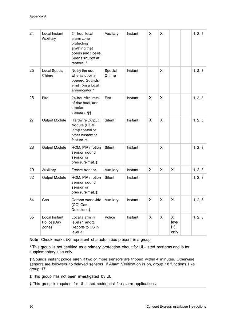
Appendix A
90 Concord Express Installation Instructions
24 Local Instant
Auxiliary
24-hour local
alarm zone
protecting
anything that
opens and closes.
Sirens shut off at
restoral. *
Auxiliary
Instant
X X 1, 2, 3
25 Local Special
Chime
Notify the user
when a door is
opened. Sounds
emit from a local
annunciator. *
Special
Chime
Instant
X 1, 2, 3
26 Fire
24-hour fire, rate-
of-rise heat, and
smoke
sensors.§§
Fire
Instant
X X 1, 2, 3
27 Output Module
Hardwire Output
Module (HOM)
lamp control or
other customer
feature. ‡
Silent
Instant
X X 1, 2, 3
28 Output Module
HOM, PIR motion
sensor, sound
sensor, or
pressure mat. ‡
Silent
Instant
X 1, 2, 3
29 Auxiliary Freeze sensor. Auxiliary Instant X X X 1, 2, 3
32 Output Module
HOM, PIR motion
sensor, sound
sensor, or
pressure mat. ‡
Silent
Instant
1, 2, 3
34 Gas
Carbon monoxide
(CO) Gas
Detectors ‡
Auxiliary
Instant
X X X 1, 2, 3
35 Local Instant
Police (Day
Zone)
Local alarm in
levels 1 and 2.
Reports to CS in
level 3.
Police
Instant
X X X
leve
l 3
only
1, 2, 3
Note: Check marks (X) represent characteristics present in a group.
* This group is not certified as a primary protection circuit for UL-listed systems and is for
supplementary use only.
† Sounds instant police siren if two or more sensors are tripped within 4 minutes. Otherwise
sensors are followers to delayed sensors. If Alarm Verification is on, group 18 functions l ike
group 17.
‡ This group has not been investigated by UL.
§ This group is required for UL-listed residential fire alarm applications.
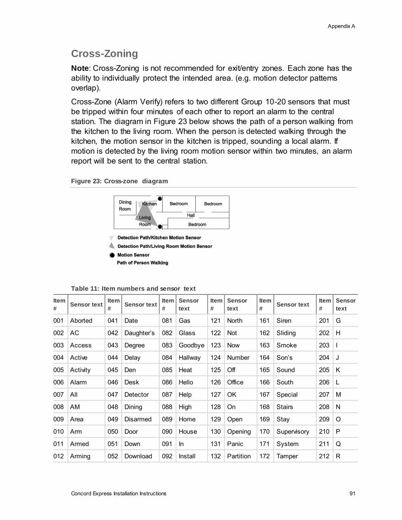
Appendix A
Concord Express Installation Instructions 91
Cross-Zoning
Note: Cross-Zoning is not recommended for exit/entry zones. Each zone has the
ability to individually protect the intended area. (e.g. motion detector patterns
overlap).
Cross-Zone (Alarm Verify) refers to two different Group 10-20 sensors that must
be tripped within four minutes of each other to report an alarm to the central
station. The diagram in Figure 23 below shows the path of a person walking from
the kitchen to the living room. When the person is detected walking through the
kitchen, the motion sensor in the kitchen is tripped, sounding a local alarm. If
motion is detected by the living room motion sensor within two minutes, an alarm
report will be sent to the central station.
Figure 23: Cross-zone diagram
Table 11: Item numbers and sensor text
Item
# Sensor text
Item
# Sensor text
Item
#
Sensor
text
Item
#
Sensor
text
Item
# Sensor text
Item
#
Sensor
text
001 Aborted 041 Date 081 Gas 121 North 161 Siren 201 G
002 AC 042 Daughter’s 082 Glass 122 Not 162 Sliding 202 H
003 Access 043 Degree 083 Goodbye 123 Now 163 Smoke 203 I
004 Active 044 Delay 084 Hallway 124 Number 164 Son’s 204 J
005 Activity 045 Den 085 Heat 125 Off 165 Sound 205 K
006 Alarm 046 Desk 086 Hello 126 Office 166 South 206 L
007 All 047 Detector 087 Help 127 OK 167 Special 207 M
008 AM 048 Dining 088 High 128 On 168 Stairs 208 N
009 Area 049 Disarmed 089 Home 129 Open 169 Stay 209 O
010 Arm 050 Door 090 House 130 Opening 170 Supervisory 210 P
011 Armed 051 Down 091 In 131 Panic 171 System 211 Q
012 Arming 052 Download 092 Install 132 Partition 172 Tamper 212 R
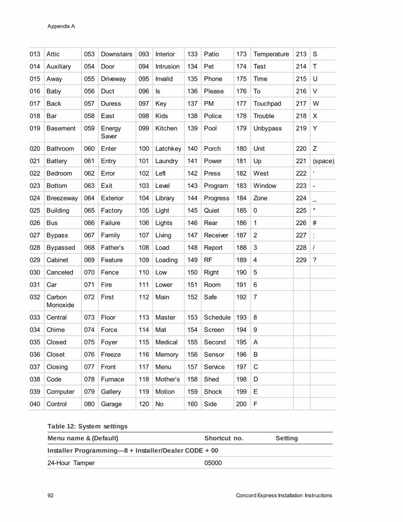
Appendix A
92 Concord Express Installation Instructions
013 Attic 053 Downstairs 093 Interior 133 Patio 173 Temperature 213 S
014 Auxiliary 054 Door 094 Intrusion 134 Pet 174 Test 214 T
015 Away 055 Driveway 095 Invalid 135 Phone 175 Time 215 U
016 Baby 056 Duct 096 Is 136 Please 176 To 216 V
017 Back 057 Duress 097 Key 137 PM 177 Touchpad 217 W
018 Bar 058 East 098 Kids 138 Police 178 Trouble 218 X
019 Basement 059 Energy
Saver
099 Kitchen 139 Pool 179 Unbypass 219 Y
020 Bathroom 060 Enter 100 Latchkey 140 Porch 180 Unit 220 Z
021 Battery 061 Entry 101 Laundry 141 Power 181 Up 221 (space)
022 Bedroom 062 Error 102 Left 142 Press 182 West 222 ‘
023 Bottom 063 Exit 103 Level 143 Program 183 Window 223 -
024 Breezeway 064 Exterior 104 Library 144 Progress 184 Zone 224 _
025 Building 065 Factory 105 Light 145 Quiet 185 0 225 *
026 Bus 066 Failure 106 Lights 146 Rear 186 1 226 #
027 Bypass 067 Family 107 Living 147 Receiver 187 2 227 :
028 Bypassed 068 Father’s 108 Load 148 Report 188 3 228 /
029 Cabinet 069 Feature 109 Loading 149 RF 189 4 229 ?
030 Canceled 070 Fence 110 Low 150 Right 190 5
031 Car 071 Fire 111 Lower 151 Room 191 6
032 Carbon
Monoxide
072 First 112 Main 152 Safe 192 7
033 Central 073 Floor 113 Master 153 Schedule 193 8
034 Chime 074 Force 114 Mat 154 Screen 194 9
035 Closed 075 Foyer 115 Medical 155 Second 195 A
036 Closet 076 Freeze 116 Memory 156 Sensor 196 B
037 Closing 077 Front 117 Menu 157 Service 197 C
038 Code 078 Furnace 118 Mother’s 158 Shed 198 D
039 Computer 079 Gallery 119 Motion 159 Shock 199 E
040 Control 080 Garage 120 No 160 Side 200 F
Table 12: System settings
Menu name & (Default) Shortcut no. Setting
Installer Programming—8 + Installer/Dealer CODE + 00
24-Hour Tamper 05000
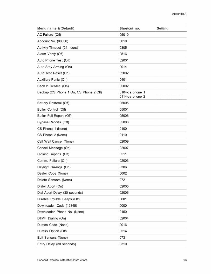
Appendix A
Concord Express Installation Instructions 93
Menu name & (Default) Shortcut no. Setting
AC Failure (Off) 05010
Account No. (00000) 0010
Activity Timeout (24 hours) 0305
Alarm Verify (Off) 0516
Auto Phone Test (Off) 02001
Auto Stay Arming (On) 0014
Auto Test Reset (On) 02002
Auxiliary Panic (On) 0401
Back In Service (On) 05002
Backup (CS Phone 1 On, CS Phone 2 Off) 0104-cs phone 1
0114-cs phone 2
______________
______________
Battery Restoral (Off) 05005
Buffer Control (Off) 05001
Buffer Full Report (Off) 05006
Bypass Reports (Off) 05003
CS Phone 1 (None) 0100
CS Phone 2 (None) 0110
Call Wait Cancel (None) 02009
Cancel Message (On) 02007
Closing Reports (Off) 0511
Comm. Failure (On) 02003
Daylight Savings (On) 0306
Dealer Code (None) 0002
Delete Sensors (None) 072
Dialer Abort (On) 02005
Dial Abort Delay (30 seconds) 02006
Disable Trouble Beeps (Off) 0601
Downloader Code (12345) 0000
Downloader Phone No. (None) 0150
DTMF Dialing (On) 02004
Duress Code (None) 0016
Duress Option (Off) 0514
Edit Sensors (None) 073
Entry Delay (30 seconds) 0310
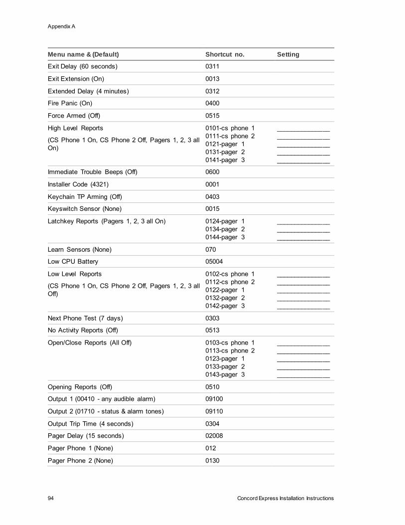
Appendix A
94 Concord Express Installation Instructions
Menu name & (Default) Shortcut no. Setting
Exit Delay (60 seconds) 0311
Exit Extension (On) 0013
Extended Delay (4 minutes) 0312
Fire Panic (On) 0400
Force Armed (Off) 0515
High Level Reports
(CS Phone 1 On, CS Phone 2 Off, Pagers 1, 2, 3 all
On)
0101-cs phone 1
0111-cs phone 2
0121-pager 1
0131-pager 2
0141-pager 3
_______________
_______________
_______________
_______________
_______________
Immediate Trouble Beeps (Off) 0600
Installer Code (4321) 0001
Keychain TP Arming (Off) 0403
Keyswitch Sensor (None) 0015
Latchkey Reports (Pagers 1, 2, 3 all On) 0124-pager 1
0134-pager 2
0144-pager 3
_______________
_______________
_______________
Learn Sensors (None) 070
Low CPU Battery 05004
Low Level Reports
(CS Phone 1 On, CS Phone 2 Off, Pagers 1, 2, 3 all
Off)
0102-cs phone 1
0112-cs phone 2
0122-pager 1
0132-pager 2
0142-pager 3
_______________
_______________
_______________
_______________
_______________
Next Phone Test (7 days) 0303
No Activity Reports (Off) 0513
Open/Close Reports (All Off) 0103-cs phone 1
0113-cs phone 2
0123-pager 1
0133-pager 2
0143-pager 3
_______________
_______________
_______________
_______________
_______________
Opening Reports (Off) 0510
Output 1 (00410 - any audible alarm) 09100
Output 2 (01710 - status & alarm tones) 09110
Output Trip Time (4 seconds) 0304
Pager Delay (15 seconds) 02008
Pager Phone 1 (None) 012
Pager Phone 2 (None) 0130
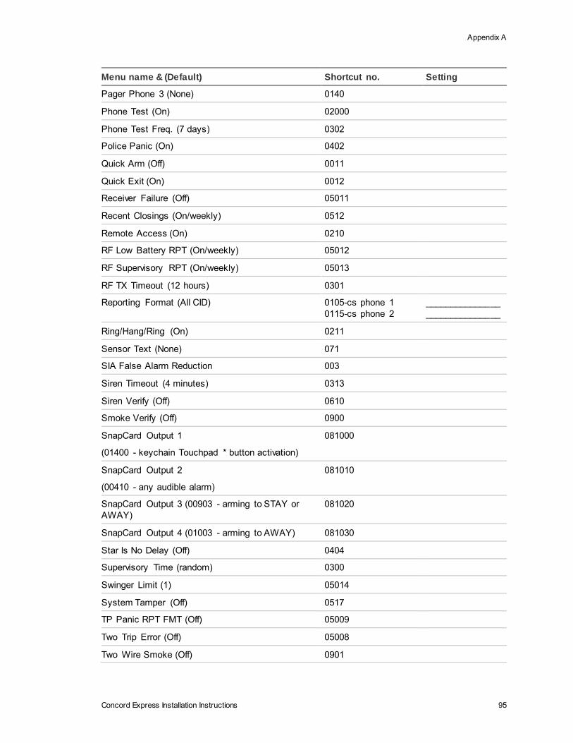
Appendix A
Concord Express Installation Instructions 95
Menu name & (Default) Shortcut no. Setting
Pager Phone 3 (None) 0140
Phone Test (On) 02000
Phone Test Freq. (7 days) 0302
Police Panic (On) 0402
Quick Arm (Off) 0011
Quick Exit (On) 0012
Receiver Failure (Off) 05011
Recent Closings (On/weekly) 0512
Remote Access (On) 0210
RF Low Battery RPT (On/weekly) 05012
RF Supervisory RPT (On/weekly) 05013
RF TX Timeout (12 hours) 0301
Reporting Format (All CID) 0105-cs phone 1
0115-cs phone 2
_______________
_______________
Ring/Hang/Ring (On) 0211
Sensor Text (None) 071
SIA False Alarm Reduction 003
Siren Timeout (4 minutes) 0313
Siren Verify (Off) 0610
Smoke Verify (Off) 0900
SnapCard Output 1
(01400 - keychain Touchpad * button activation)
081000
SnapCard Output 2
(00410 - any audible alarm)
081010
SnapCard Output 3 (00903 - arming to STAY or
AWAY)
081020
SnapCard Output 4 (01003 - arming to AWAY) 081030
Star Is No Delay (Off) 0404
Supervisory Time (random) 0300
Swinger Limit (1) 05014
System Tamper (Off) 0517
TP Panic RPT FMT (Off) 05009
Two Trip Error (Off) 05008
Two Wire Smoke (Off) 0901
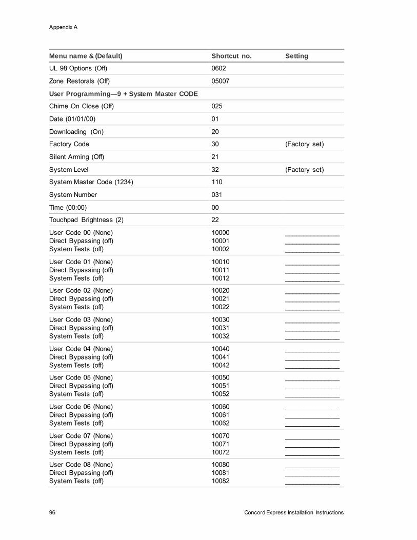
Appendix A
96 Concord Express Installation Instructions
Menu name & (Default) Shortcut no. Setting
UL 98 Options (Off) 0602
Zone Restorals (Off) 05007
User Programming—9 + System Master CODE
Chime On Close (Off) 025
Date (01/01/00) 01
Downloading (On) 20
Factory Code 30 (Factory set)
Silent Arming (Off) 21
System Level 32 (Factory set)
System Master Code (1234) 110
System Number 031
Time (00:00) 00
Touchpad Brightness (2) 22
User Code 00 (None)
Direct Bypassing (off)
System Tests (off)
10000
10001
10002
_______________
_______________
_______________
User Code 01 (None)
Direct Bypassing (off)
System Tests (off)
10010
10011
10012
_______________
_______________
_______________
User Code 02 (None)
Direct Bypassing (off)
System Tests (off)
10020
10021
10022
_______________
_______________
_______________
User Code 03 (None)
Direct Bypassing (off)
System Tests (off)
10030
10031
10032
_______________
_______________
_______________
User Code 04 (None)
Direct Bypassing (off)
System Tests (off)
10040
10041
10042
_______________
_______________
_______________
User Code 05 (None)
Direct Bypassing (off)
System Tests (off)
10050
10051
10052
_______________
_______________
_______________
User Code 06 (None)
Direct Bypassing (off)
System Tests (off)
10060
10061
10062
_______________
_______________
_______________
User Code 07 (None)
Direct Bypassing (off)
System Tests (off)
10070
10071
10072
_______________
_______________
_______________
User Code 08 (None)
Direct Bypassing (off)
System Tests (off)
10080
10081
10082
_______________
_______________
_______________
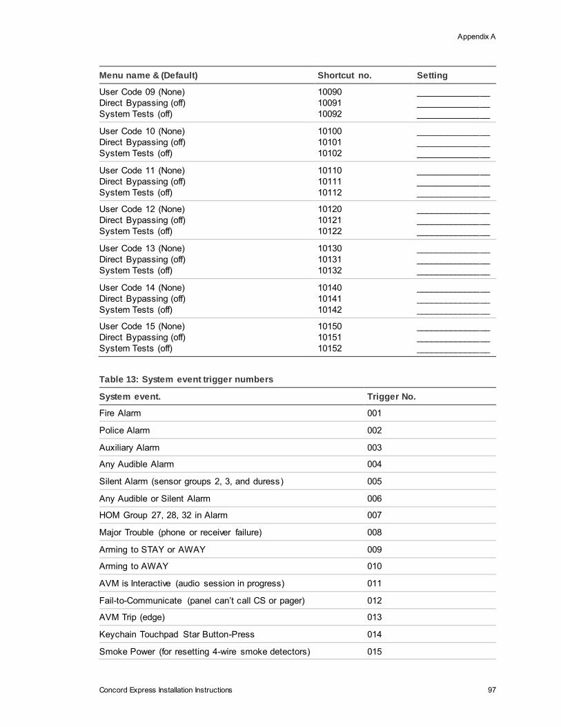
Appendix A
Concord Express Installation Instructions 97
Menu name & (Default) Shortcut no. Setting
User Code 09 (None)
Direct Bypassing (off)
System Tests (off)
10090
10091
10092
_______________
_______________
_______________
User Code 10 (None)
Direct Bypassing (off)
System Tests (off)
10100
10101
10102
_______________
_______________
_______________
User Code 11 (None)
Direct Bypassing (off)
System Tests (off)
10110
10111
10112
_______________
_______________
_______________
User Code 12 (None)
Direct Bypassing (off)
System Tests (off)
10120
10121
10122
_______________
_______________
_______________
User Code 13 (None)
Direct Bypassing (off)
System Tests (off)
10130
10131
10132
_______________
_______________
_______________
User Code 14 (None)
Direct Bypassing (off)
System Tests (off)
10140
10141
10142
_______________
_______________
_______________
User Code 15 (None)
Direct Bypassing (off)
System Tests (off)
10150
10151
10152
_______________
_______________
_______________
Table 13: System event trigger numbers
System event. Trigger No.
Fire Alarm 001
Police Alarm 002
Auxiliary Alarm 003
Any Audible Alarm 004
Silent Alarm (sensor groups 2, 3, and duress) 005
Any Audible or Silent Alarm 006
HOM Group 27, 28, 32 in Alarm 007
Major Trouble (phone or receiver failure) 008
Arming to STAY or AWAY 009
Arming to AWAY 010
AVM is Interactive (audio session in progress) 011
Fail-to-Communicate (panel can’t call CS or pager) 012
AVM Trip (edge) 013
Keychain Touchpad Star Button-Press 014
Smoke Power (for resetting 4-wire smoke detectors) 015
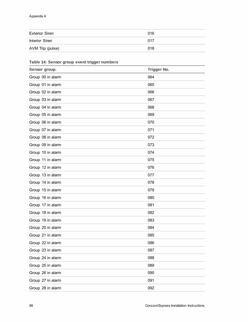
Appendix A
98 Concord Express Installation Instructions
Exterior Siren 016
Interior Siren 017
AVM Trip (pulse) 018
Table 14: Sensor group event trigger numbers
Sensor group. Trigger No.
Group 00 in alarm 064
Group 01 in alarm 065
Group 02 in alarm 066
Group 03 in alarm 067
Group 04 in alarm 068
Group 05 in alarm 069
Group 06 in alarm 070
Group 07 in alarm 071
Group 08 in alarm 072
Group 09 in alarm 073
Group 10 in alarm 074
Group 11 in alarm 075
Group 12 in alarm 076
Group 13 in alarm 077
Group 14 in alarm 078
Group 15 in alarm 079
Group 16 in alarm 080
Group 17 in alarm 081
Group 18 in alarm 082
Group 19 in alarm 083
Group 20 in alarm 084
Group 21 in alarm 085
Group 22 in alarm 086
Group 23 in alarm 087
Group 24 in alarm 088
Group 25 in alarm 089
Group 26 in alarm 090
Group 27 in alarm 091
Group 28 in alarm 092
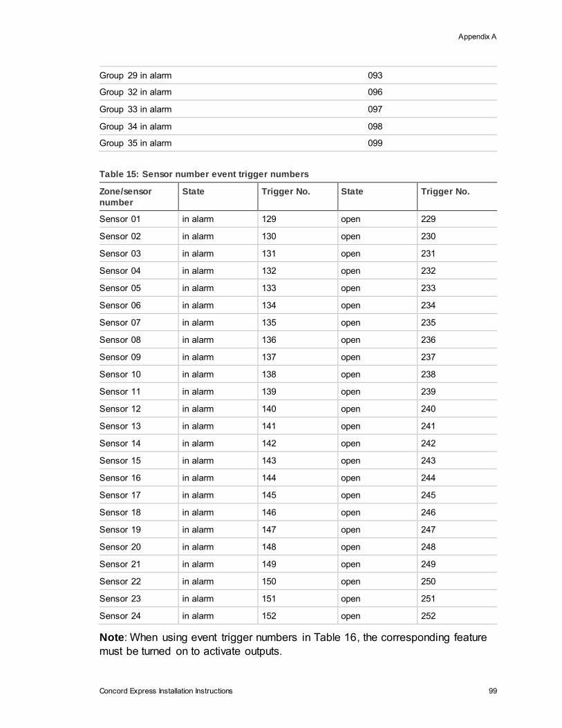
Appendix A
Concord Express Installation Instructions 99
Group 29 in alarm 093
Group 32 in alarm 096
Group 33 in alarm 097
Group 34 in alarm 098
Group 35 in alarm 099
Table 15: Sensor number event trigger numbers
Zone/sensor
number
State Trigger No. State Trigger No.
Sensor 01 in alarm 129 open 229
Sensor 02 in alarm 130 open 230
Sensor 03 in alarm 131 open 231
Sensor 04 in alarm 132 open 232
Sensor 05 in alarm 133 open 233
Sensor 06 in alarm 134 open 234
Sensor 07 in alarm 135 open 235
Sensor 08 in alarm 136 open 236
Sensor 09 in alarm 137 open 237
Sensor 10 in alarm 138 open 238
Sensor 11 in alarm 139 open 239
Sensor 12 in alarm 140 open 240
Sensor 13 in alarm 141 open 241
Sensor 14 in alarm 142 open 242
Sensor 15 in alarm 143 open 243
Sensor 16 in alarm 144 open 244
Sensor 17 in alarm 145 open 245
Sensor 18 in alarm 146 open 246
Sensor 19 in alarm 147 open 247
Sensor 20 in alarm 148 open 248
Sensor 21 in alarm 149 open 249
Sensor 22 in alarm 150 open 250
Sensor 23 in alarm 151 open 251
Sensor 24 in alarm 152 open 252
Note: When using event trigger numbers in Table 16, the corresponding feature
must be turned on to activate outputs.
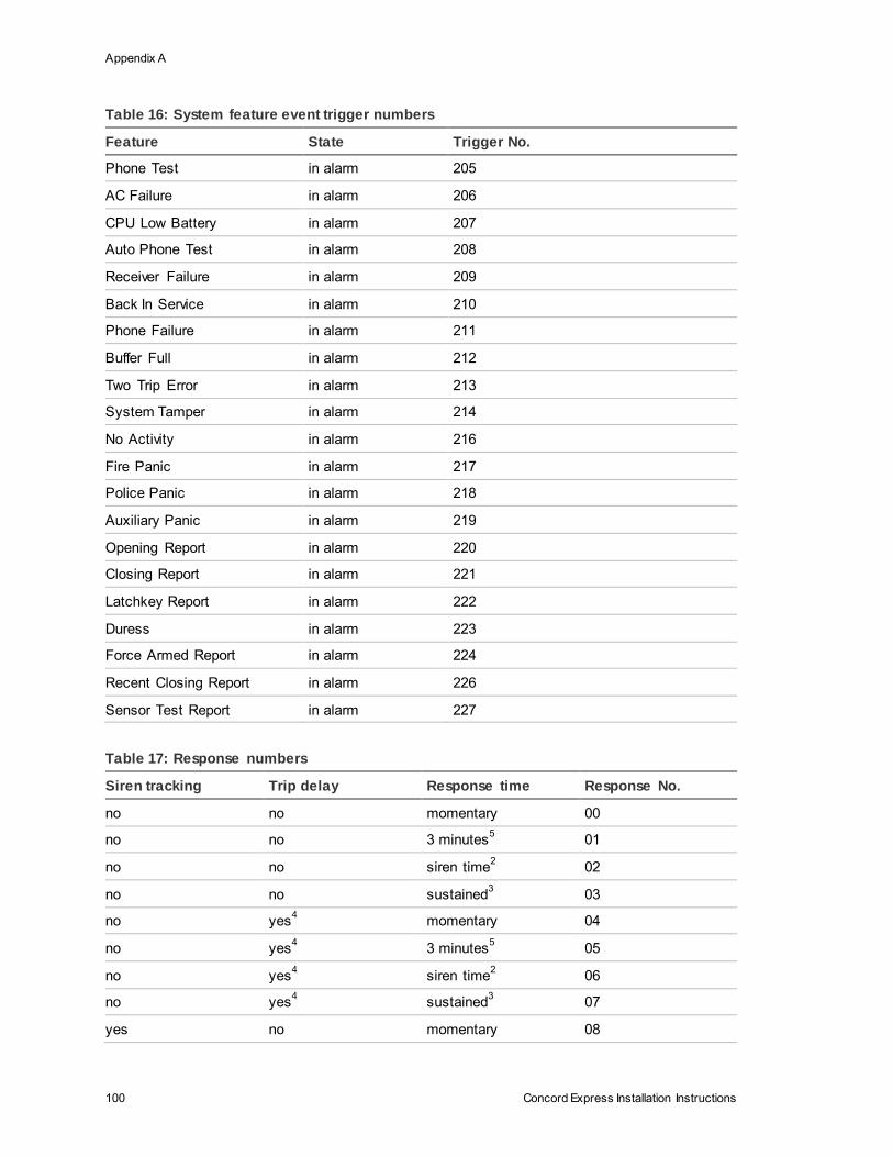
Appendix A
100 Concord Express Installation Instructions
Table 16: System feature event trigger numbers
Feature State Trigger No.
Phone Test in alarm 205
AC Failure in alarm 206
CPU Low Battery in alarm 207
Auto Phone Test in alarm 208
Receiver Failure in alarm 209
Back In Service in alarm 210
Phone Failure in alarm 211
Buffer Full in alarm 212
Two Trip Error in alarm 213
System Tamper in alarm 214
No Activity in alarm 216
Fire Panic in alarm 217
Police Panic in alarm 218
Auxiliary Panic in alarm 219
Opening Report in alarm 220
Closing Report in alarm 221
Latchkey Report in alarm 222
Duress in alarm 223
Force Armed Report in alarm 224
Recent Closing Report in alarm 226
Sensor Test Report in alarm 227
Table 17: Response numbers
Siren tracking Trip delay Response time Response No.
no no momentary 00
no no 3 minutes5 01
no no siren time2 02
no no sustained3 03
no yes4 momentary 04
no yes4 3 minutes
5 05
no yes4 siren time
2 06
no yes4 sustained
3 07
yes no momentary 08
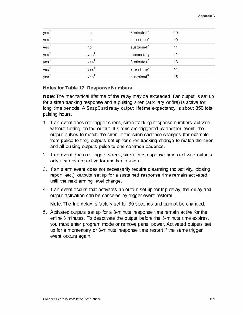
Appendix A
Concord Express Installation Instructions 101
yes1 no 3 minutes
5 09
yes1 no siren time
2 10
yes1 no sustained
3 11
yes1 yes
4 momentary 12
yes1 yes
4 3 minutes
5 13
yes1 yes
4 siren time
2 14
yes1 yes
4 sustained
3 15
Notes for Table 17 Response Numbers
Note: The mechanical lifetime of the relay may be exceeded if an output is set up
for a siren tracking response and a pulsing siren (auxiliary or fire) is active for
long time periods. A SnapCard relay output lifetime expectancy is about 350 total
pulsing hours.
1. If an event does not trigger sirens, siren tracking response numbers activate
without turning on the output. If sirens are triggered by another event, the
output pulses to match the siren. If the siren cadence changes (for example
from police to fire), outputs set up for siren tracking change to match the siren
and all pulsing outputs pulse to one common cadence.
2. If an event does not trigger sirens, siren time response times activate outputs
only if sirens are active for another reason.
3. If an alarm event does not necessarily require disarming (no activity, closing
report, etc.), outputs set up for a sustained response time remain activated
until the next arming level change.
4. If an event occurs that activates an output set up for trip delay, the delay and
output activation can be canceled by trigger event restoral.
Note: The trip delay is factory set for 30 seconds and cannot be changed.
5. Activated outputs set up for a 3-minute response time remain active for the
entire 3 minutes. To deactivate the output before the 3-minute time expires,
you must enter program mode or remove panel power. Activated outputs set
up for a momentary or 3-minute response time restart if the same trigger
event occurs again.

Concord Express Installation Instructions 103
Appendix B Programming mode menus and settings
Use the following graphics to follow programming modes and menus.
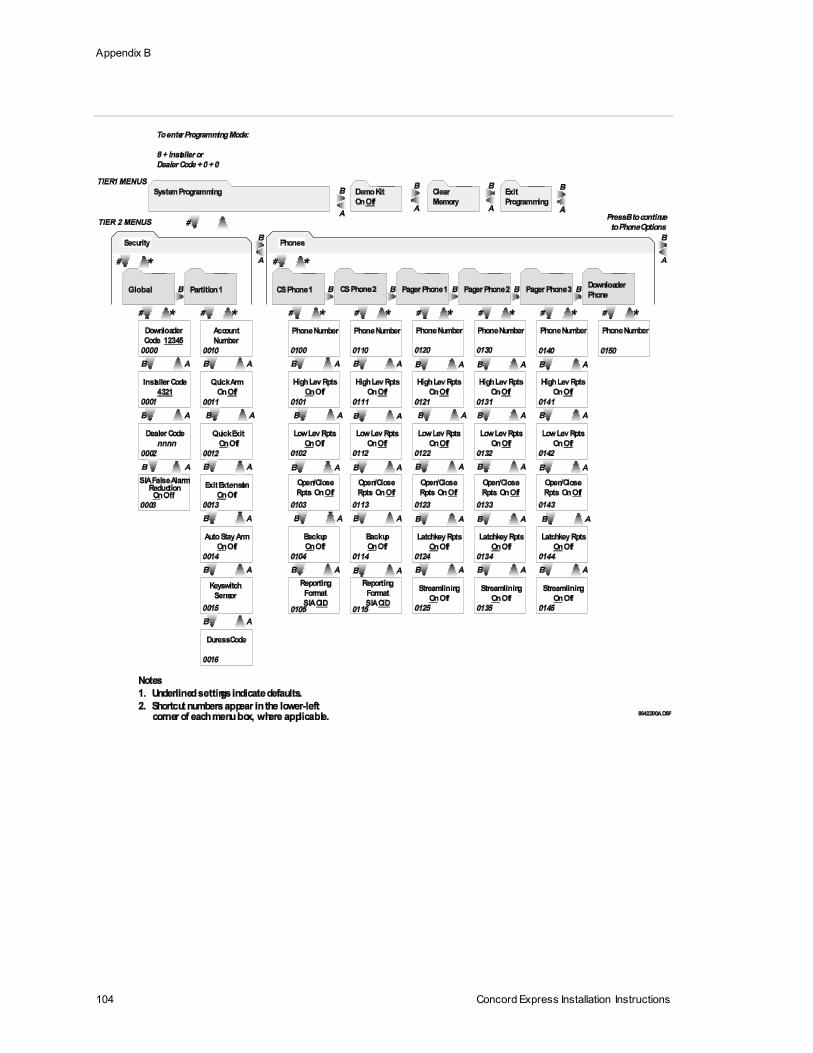
Appendix B
104 Concord Express Installation Instructions

Appendix B
Concord Express Installation Instructions 105
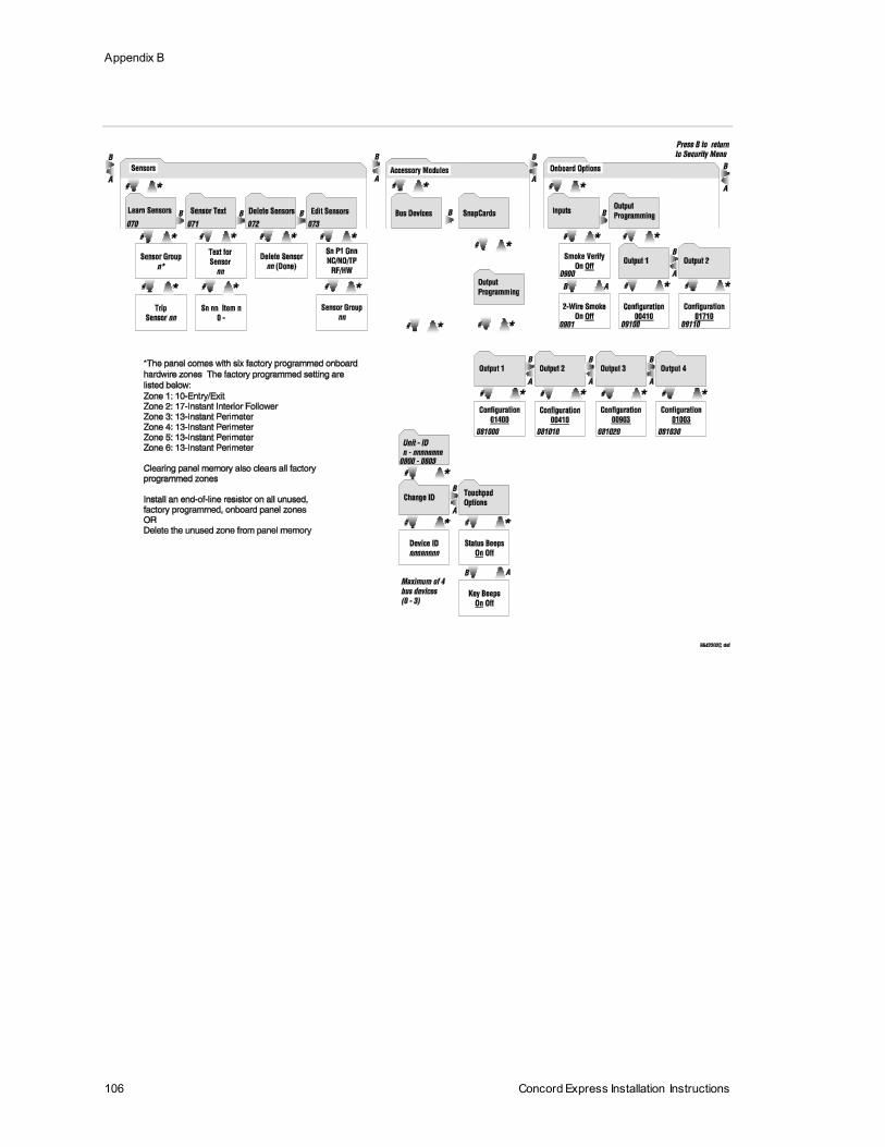
Appendix B
106 Concord Express Installation Instructions
Concord Express Installation Instructions 107
Appendix C Software release notes and specifications
Software Version 1.73
The following features were changed/added for software version 1.73.
Downloader Code
• If the Dealer Code (0002) is set, the Installer Code (0001) can’t view or edit
the Downloader Code (0000)
• Downloader Code and CS Phone Numbers (0100/0110) are NOT reset by a
memory clear operation using the Installer Code if the Dealer Code has been
set. Using the Dealer Code for memory clear will include Downloader Code
and CS Phone Numbers in the memory clear.
SIA False Alarm
• SIA False Alarm (0003) option has been added to control access to Silent
Arming (21) in user programming. If SIA False Alarm is off, Silent Arming is
available in user programming. If SIA False Alarm is on, Silent Arming is
forced to off and is not available in user programming. SIA False Alarm
defaults to on.
• SIA False Alarm control annunciating alarm level changes on exterior sirens.
If SIA False Alarm is on, the arming level is annunciated on exterior siren
output during an arming level change that is initiated by an RF device
(touchpad or keyfob). If SIA False Alarm is off, the arming level is NOT
annunciated on exterior siren output.

Appendix C
108 Concord Express Installation Instructions
Central Station Reports
• An exit error event now sends an Entry/Exit Alarm and Exit Error reports to
the central station.
In CID format the report is: (CID: 457,user# and 134,zone#)
IN SIA format the report is: (SIA: EE,user# and BA,zone#)
Entry Delay
• During Entry Delay the system can now be disarmed by entering a valid
access code only. 1 + CODE is no longer required, but will still work.
• The low limit and default setting on Entry Delay has been changed from 32 to
30 seconds. Existing versions of Toolbox will still show a low limit and default
setting of 32 seconds. When setting the Entry Delay in installer program
mode, entering any number between 30 and 39 will result in an Entry Delay of
30 seconds.
Exit Delay
• The low limit on Exit Delay has been changed from 48 to 45 seconds, with the
default setting changing from 64 to 60 seconds. Existing versions of Toolbox
will still show a default setting of 64 seconds. When setting the Exit Delay in
installer program mode, entering any number between 45 and 55 will result in
an Exit Delay of 45 seconds and entering any number between 60 and 71 will
result in an Exit Delay of 60 seconds.
Dialer Abort Delay
• The allowed range for Dialer Abort Delay (02006) has been changed from 15-
120 seconds to 15-45 seconds.
• Abort delay is now used before every alarm, even alarms that occur during
another alarm report. In the previous release, an alarm that came in during
reporting of another event did not have a dial abort delay.
Disarming
• Disarming the system after an alarm when the siren has timed out can now
be done by entering the access code. 1 + CODE is no longer required, but will
still work.
• After disarming and canceling an alarm, the system now displays all the
alarms that have occurred since the last disarming.
Downloader
• Eavesdrop delay for carrier detect on downloader call in is now 5 seconds
instead of 2 seconds. This change should eliminate problems connecting with
the downloader.
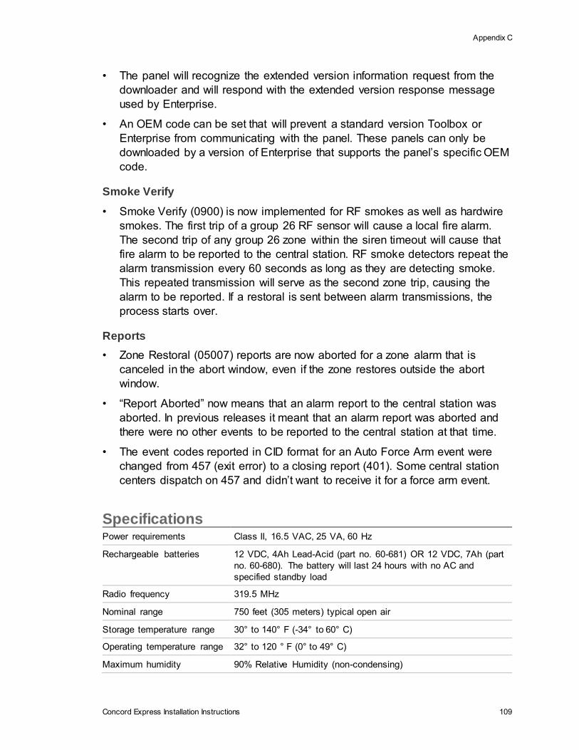
Appendix C
Concord Express Installation Instructions 109
• The panel will recognize the extended version information request from the
downloader and will respond with the extended version response message
used by Enterprise.
• An OEM code can be set that will prevent a standard version Toolbox or
Enterprise from communicating with the panel. These panels can only be
downloaded by a version of Enterprise that supports the panel’s specific OEM
code.
Smoke Verify
• Smoke Verify (0900) is now implemented for RF smokes as well as hardwire
smokes. The first trip of a group 26 RF sensor will cause a local fire alarm.
The second trip of any group 26 zone within the siren timeout will cause that
fire alarm to be reported to the central station. RF smoke detectors repeat the
alarm transmission every 60 seconds as long as they are detecting smoke.
This repeated transmission will serve as the second zone trip, causing the
alarm to be reported. If a restoral is sent between alarm transmissions, the
process starts over.
Reports
• Zone Restoral (05007) reports are now aborted for a zone alarm that is
canceled in the abort window, even if the zone restores outside the abort
window.
• “Report Aborted” now means that an alarm report to the central station was
aborted. In previous releases it meant that an alarm report was aborted and
there were no other events to be reported to the central station at that time.
• The event codes reported in CID format for an Auto Force Arm event were
changed from 457 (exit error) to a closing report (401). Some central station
centers dispatch on 457 and didn’t want to receive it for a force arm event.
Specifications Power requirements Class II, 16.5 VAC, 25 VA, 60 Hz
Rechargeable batteries 12 VDC, 4Ah Lead-Acid (part no. 60-681) OR 12 VDC, 7Ah (part
no. 60-680). The battery will last 24 hours with no AC and
specified standby load
Radio frequency 319.5 MHz
Nominal range 750 feet (305 meters) typical open air
Storage temperature range 30° to 140° F (-34° to 60° C)
Operating temperature range 32° to 120 ° F (0° to 49° C)
Maximum humidity 90% Relative Humidity (non-condensing)
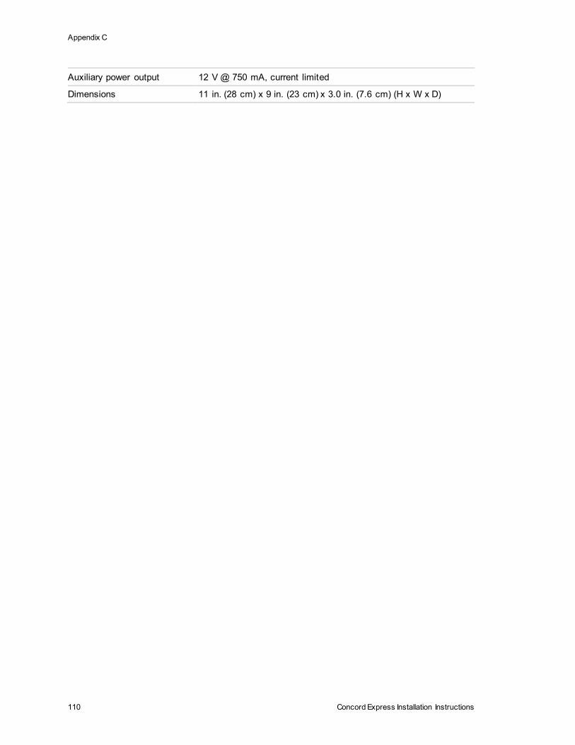
Appendix C
110 Concord Express Installation Instructions
Auxiliary power output 12 V @ 750 mA, current limited
Dimensions 11 in. (28 cm) x 9 in. (23 cm) x 3.0 in. (7.6 cm) (H x W x D)


