Download - Computers and You

Simple
Internetworking
Hui Chen, Ph.D.
Department of Engineering & Computer Science
Virginia State University
Petersburg, VA 23806
09/23/2015 1CSCI 445 – Fall 2015

Acknowledgements
Some pictures used in this presentation were obtained from the
Internet
The instructor used the following references
Larry L. Peterson and Bruce S. Davie, Computer Networks: A Systems
Approach, 5th Edition, Elsevier, 2011
Andrew S. Tanenbaum, Computer Networks, 5th Edition, Prentice-
Hall, 2010
James F. Kurose and Keith W. Ross, Computer Networking: A Top-
Down Approach, 5th Ed., Addison Wesley, 2009
Larry L. Peterson’s (http://www.cs.princeton.edu/~llp/) Computer
Networks class web site
09/21/2015 CSCI 445 – Fall 2015 2

Outline Topic: internetworking
Case study: Internet Protocol (IP) Suite
Simple interworking internet and the Internet
Global addressing scheme
Packet fragmentation and assembly
Best effort service model and datagram forwarding
Address translation
Host configuration
Error reporting
09/23/2015 3CSCI 445 – Fall 2015

Heterogeneity and Scalability
LAN: small in size
How to extend LAN?
Bridges and switches
Good for global networks?
Spanning tree algorithms very long path and huge forwarding tables
Bridges and switches: link level/layer 2 devices networks must be using the same type of links
Problems to deal with
Scalability: global networks are huge in size
Heterogeneity: networks of different types of links are in use
09/23/2015 4CSCI 445 – Fall 2015
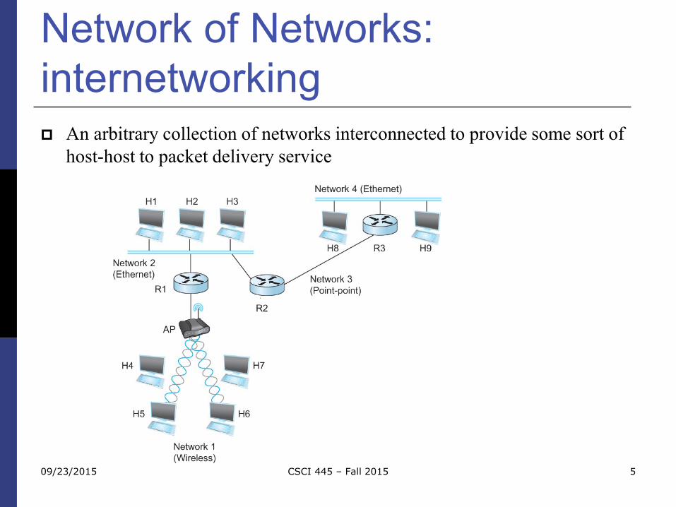
Network of Networks:
internetworking
5CSCI 445 – Fall 201509/23/2015
An arbitrary collection of networks interconnected to provide some sort of
host-host to packet delivery service

Solution to Scalability: Network of
Networks
Forwarding packets to networks from networks: smaller forwarding tables
09/23/2015 6CSCI 445 – Fall 2015

Solution to Heterogeneity: layered
architecture and hourglass design
09/23/2015 CSCI 445 – Fall 2015 7
Network layer encapsulates the heterogeneity and the complexity of data link and physical layers (or the host-to-network layer)

Network Layer and Lower
Layers
Link Layer(type 1)
Link Layer(type 2)
Network layer
Adapter
OS Network layer packet
Network layer packet as payload
Route
r
09/23/2015 8CSCI 445 – Fall 2015

Internet Protocol
9CSCI 445 – Fall 201509/23/2015
IP = Internet Protocol
Key tool used today to build scalable, heterogeneous internetworks
Routers forward packets to “networks”: forwarding tables can be smaller
Above link layer: can cope with different link layer technology
Runs on all the nodes in a collection of networks
Defines the infrastructure
Allows these nodes and networks to function as
a single logical internetwork

Case Study: The Internet
Global internetworks built on IP The Internet internet
Using Internet Protocol (IP) as a case study
Datagram forwarding and service model
IP packet format and global IP addressing scheme
Deal with Link layer and network layer interfacing Packet fragmentation and assembly
Address translation
Other important issues
Host configuration
Error reporting
09/23/2015 10CSCI 445 – Fall 2015
IP Service Model
Packet Delivery Model
Connectionless model for data delivery
Best-effort delivery (unreliable service)
packets may be lost
packets may be delivered out of order
duplicate copies of a packet may be delivered
packets may be delayed for a long time
Global Addressing Scheme
Provides a way to identify all hosts in the network
09/23/2015 CSCI 445 – Fall 2015 11

Basic Data Structure: IP Packet
Design Goals
Attributes and purposes
Support error detection and handling
Support networks as a forwarding source and destinations
Support different networking technologies
Support multiplexing
Support extensibility
09/23/2015 CSCI 445 – Fall 2015 12

IP Packet Format (1)
Discussing IP version 4 (IPv4). Discussing IP version
6in later lessons
Convention used to illustrate IP packet
32 bit words
Top word transmit first
Left-most byte transmit first
09/23/2015 13CSCI 445 – Fall 2015

Packet Format Version (4): 4 or 6. The rest is for version
4. Discussing 6 in later lessons
Hlen (4): number of 32-bit words in header
TOS (8): type of service (not widely used)
Length (16): number of bytes in this datagram
Ident (16): used by fragmentation
Flags/Offset (16): used by fragmentation
TTL (8): number of hops this datagram has traveled
Protocol (8): demux key (TCP=6, UDP=17)
Checksum (16): of the header only
DestAddr & SrcAddr (32)
09/23/2015 CSCI 445 – Fall 2015 14
Capturing an IP Packet
And examining it …
Use the ethercap application (a part of homework 1)
Use Wireshark
Use Microsoft Network Monitor (Message Analyzer)
Use tcpdump
Use libpcap in your own application
……
09/23/2015 CSCI 445 – Fall 2015 15

Using Wireshark
09/23/2015 16CSCI 445 – Fall 2015

IP Packet
DATAIP Header
DATA
DATAIP HeaderLink Layer Header
09/23/2015 17CSCI 445 – Fall 2015

A Captured IP Packet
09/23/2015 18CSCI 445 – Fall 2015

Ethernet Protocol Numbers
09/23/2015 19CSCI 445 – Fall 2015

Exercise L10-1
Below shows a captured
Ethernet frame
Q1: what is the length in bytes of
the largest IP packet?
Q2: what is the length in bytes of
the smallest IP packet?
Q3: what are the values (bits) of
each field in the IP packet below
(underlined). Which byte is the
last byte of this IP packet?
09/23/2015 CSCI 445 – Fall 2015 20

IP Fragmentation and
Reassembly Each network has some MTU (Maximum
Transmission Unit) Ethernet (1500 bytes), FDDI (4500 bytes)
Strategy Fragmentation occurs in a router when it receives a
datagram that it wants to forward over a network which has (MTU < datagram)
Reassembly is done at the receiving host
All the fragments carry the same identifier in the Ident field
Fragments are self-contained datagrams
IP does not recover from missing fragments
09/23/2015 CSCI 445 – Fall 2015 21

IP Fragmentation and
Reassembly: Example
IP packet
Data: 1400 bytes
IP header: 20 bytes
MTU
Ethernet=1500
FDDI=4500
PPP=532
09/23/2015 CSCI 445 – Fall 2015 22

Example
MTU=1500 MTU=4500 MTU=532 MTU=1500
IP packet at H1Data: 1400 bytesIP header: 20 bytes
09/23/2015 23CSCI 445 – Fall 2015

Bit 0: reserved, must be zero Bit 1: (DF) 0 = May Fragment, 1 = Don't Fragment. Bit 2: (MF) 0 = Last Fragment, 1 = More Fragments.Source: http://www.freesoft.org/CIE/Course/Section3/7.htm
IP packet begins
IP packet ends
09/23/2015 24CSCI 445 – Fall 2015

Example
Ident:Same across all fragmentsUnique for each packet
MF (More Fragments) bit in Flags:
set more fragments to follow0 last fragment
Offsetin 8-byte chunks
Fragmented into three fragments
Q: why 8-byte chunks?
09/23/2015 25CSCI 445 – Fall 2015

Hint for “Why 8-byte Chunk?”
09/23/2015 26CSCI 445 – Fall 2015

IP Fragmentation and
Reassembly IP datagrams traversing the sequence of physical networks
09/23/2015 CSCI 445 – Fall 2015 27

Exercise L10-2
For an imaginary network below
MTU=1800 MTU=1500 MTU=512 MTU=256
Q: H1 sends an IP packet of 1800 bytes including IP header to H8. Please
show
1. IP datagrams traversing the sequence of physical networks graphed
above
2. Header fields of IP datagrams before entering and after leaving each
router and hosts09/23/2015 28CSCI 445 – Fall 2015
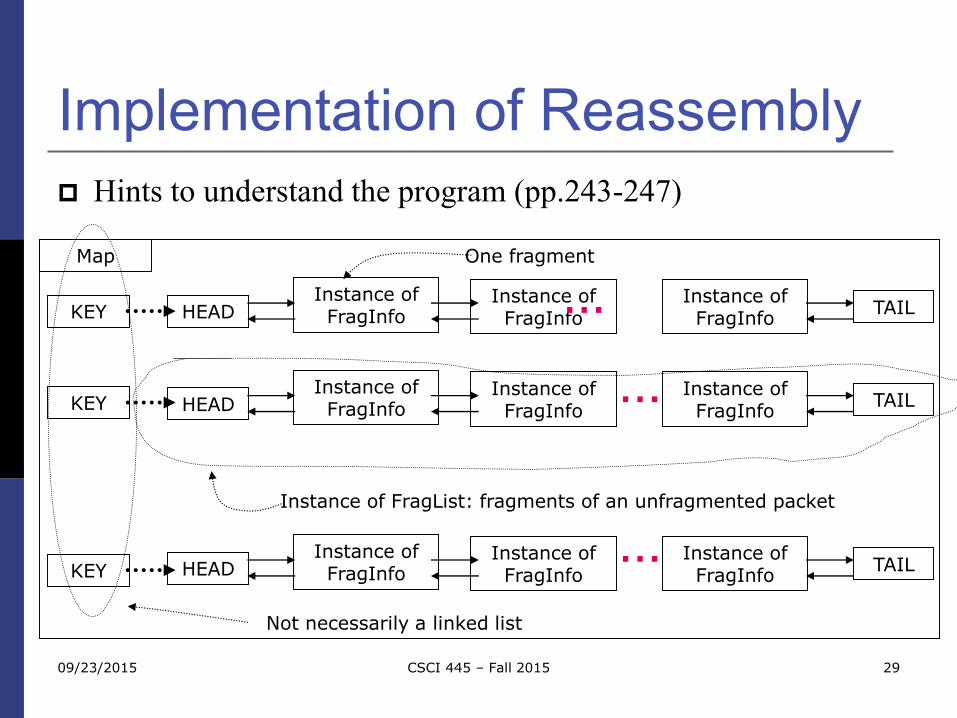
Implementation of Reassembly
Hints to understand the program (pp.243-247)
Instance of FragInfo
Instance of FragInfo
Instance of FragInfo
TAILHEAD
Instance of FragInfo
Instance of FragInfo
Instance of FragInfo
TAILHEAD
Instance of FragInfo
Instance of FragInfo
Instance of FragInfo
TAILHEAD
…
…
…
Map
KEY
KEY
KEY
Not necessarily a linked list
Instance of FragList: fragments of an unfragmented packet
One fragment
09/23/2015 29CSCI 445 – Fall 2015

Global Addresses
Internet Protocol (IP) Address
Globally unique
hierarchical: network + host
IPv4 4 Billion IPv4 addresses, half are A type, ¼ is B type, and
1/8 is C type
32 bit integer
Human-readable form: IPv4 numbers-and-dots notation 150.174.44.57
Facing exhaustion of address space, moving to IPv6
09/23/2015 30CSCI 445 – Fall 2015

IPv4 Address Classes (Legacy)
Classes (legacy)
To express networks
09/23/2015 CSCI 445 – Fall 2015 31
Network Host
7 24
0A:
Network Host
14 16
1 0B:
Network Host
21 8
1 1 0C:
Classes

Broadcast and Multicast
Addresses
Do the classes of IP addresses discussed including
any IP addresses starting with bits 111?
Network Host
7 24
0A:
Network Host
14 16
1 0B:
Network Host
21 8
1 1 0C:
Classes
09/23/2015 32CSCI 445 – Fall 2015

IPv4 Multicast Address
Addresses starting with 1110
09/23/2015 CSCI 445 – Fall 2015 33
Network Host
7 24
0A:
Network Host
14 16
1 0B:
Network Host
21 8
1 1 0C:
Classes
Group Address1 1 01Multicast Address
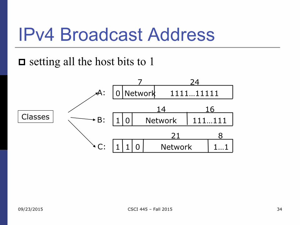
IPv4 Broadcast Address
setting all the host bits to 1
09/23/2015 CSCI 445 – Fall 2015 34
Network 1111…11111
7 24
0A:
Network 111…111
14 16
1 0B:
Network 1…1
21 8
1 1 0C:
Classes

IPv4 Address Spaces for
Private Networks
See RFC 1918
Private networks
24-bit block 10.0.0.0–10.255.255.255
20-bit block 172.16.0.0–172.31.255.255
16-bit block 192.168.0.0–192.168.255.255
09/23/2015 35CSCI 445 – Fall 2015

Link Local IPv4 Address
See RFC 3927
Link-Local IPv4 Address
16-bit block 169.254.0.0–169.254.255.255
09/23/2015 CSCI 445 – Fall 2015 36

Exercise L10-3 Find out IPv4 addresses of following hosts and indicate the class to which
the IP addresses belong
www.vsu.edu
www.drsr.sk
www.google.com
Remark
There are many ways to find out the IP address of a host given a domain name
Example: nslookup www.vsu.edu (which works on most platforms including Windows, Unix/Linux, and Mac OS X)
Convert the first number (from left) to a binary number, then take a look at the 1st, and/or 2nd, and/or 3rd bit
09/23/2015 37CSCI 445 – Fall 2015

IP Datagram Forwarding Strategy
every datagram contains destination's address
if directly connected to destination network, then forward to host
if not directly connected to destination network, then forward to some router
forwarding table maps network number into next hop
each host has a default router
each router maintains a forwarding table
09/23/2015 CSCI 445 – Fall 2015 38

Forwarding Table: Example
Forwarding table at router R2 that has two interfaces
0 and 1
09/23/2015 CSCI 445 – Fall 2015 39
01

Forwarding Algorithm
Algorithm
if (NetworkNum of destination = NetworkNum of one of
my interfaces) then
deliver packet to destination over that interface
else
if (NetworkNum of destination is in my forwarding
table) then
deliver packet to NextHop router
else
deliver packet to default router
09/23/2015 CSCI 445 – Fall 2015 40

Forwarding Algorithm
For a host with only one interface and only a default router in its forwarding table, this simplifies to
if (NetworkNum of destination = my NetworkNum)then
deliver packet to destination directly
else
deliver packet to default router
09/23/2015 CSCI 445 – Fall 2015 41

Exercise L10-4
Construct forwarding tables for routers R1 and R3.
Interfaces of routers are marked
09/23/2015 42CSCI 445 – Fall 2015
011
0
1
0

IP address to Physical Address
Translation Questions:
In an IP network, an IP packet is the payload of one or more Ethernet
frames. Who prepares the Ethernet frame headers which contain
destination Ethernet/physical address of the destination node?
How does the source node know the Ethernet/physical address of the
destination node?
Link LayerEthernet MAC
00:1E:C9:2E:F4:6D
Network layerIP = 150.174.2.101
Adapter
OS IP packet
IP packet as payload
09/23/2015 43CSCI 445 – Fall 2015

Map IP Addresses into Physical
Addresses
Map IP addresses into physical addresses
destination host
next hop router
Techniques
encode physical address in host part of IP address
table-based
ARP (Address Resolution Protocol)
table of IP to physical address bindings
broadcast request if IP address not in table
target machine responds with its physical address
table entries are discarded if not refreshed
09/23/2015 CSCI 445 – Fall 2015 44

ARP Packet Format
An ARP packet is the payload of a frameEthernet Header ARP Packet
DST SRC Type
0x0806
09/23/2015 45CSCI 445 – Fall 2015

ARP Packet Format HardwareType: type of physical network (e.g., Ethernet)
ProtocolType: type of higher layer protocol (e.g., IP)
HLEN & PLEN: length of physical and protocol addresses
Operation: request or response
Source/Target Physical/Protocol addresses
09/23/2015 CSCI 445 – Fall 2015 46
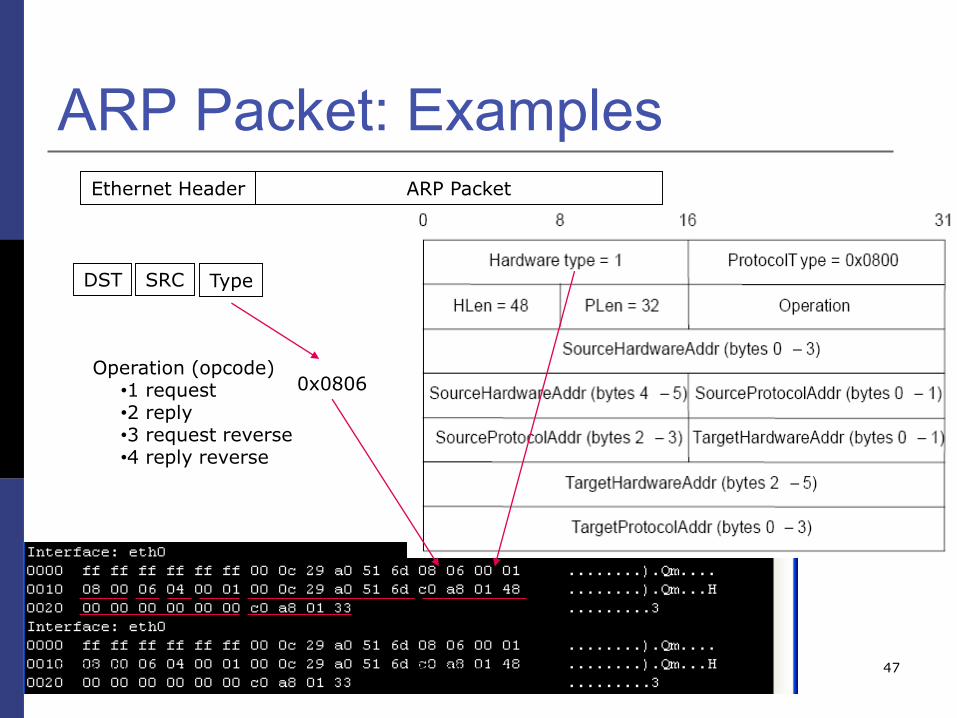
ARP Packet: ExamplesEthernet Header ARP Packet
DST SRC Type
0x0806Operation (opcode)
•1 request•2 reply•3 request reverse•4 reply reverse
09/23/2015 47CSCI 445 – Fall 2015

ARP: Discussion
Prevent stalled entries Table entries will timeout (~15 minutes)
Do not refresh table entries upon reference
Fresh entries (reset timer) Update table if already have an entry
Reduce ARP messages Update table with source when you are the target in ARP
request messages
09/23/2015 CSCI 445 – Fall 2015 48

ARP Table in Practice (1)
09/23/2015 49CSCI 445 – Fall 2015

ARP Table in Practice (2)
09/23/2015 50CSCI 445 – Fall 2015

Host Configuration
Ethernet addresses are configured into network by
manufacturer and they are unique
IP addresses must be unique on a given internetwork
but also must reflect the structure of the internetwork
Most host Operating Systems provide a way to
manually configure the IP information for the host
Drawbacks of manual configuration
A lot of work to configure all the hosts in a large network
Configuration process is error-prune
Automated Configuration Process is required09/23/2015 51CSCI 445 – Fall 2015

Dynamic Host Configuration
Protocol (DHCP)
DHCP server is responsible for providing
configuration information to hosts
There is at least one DHCP server for an
administrative domain
DHCP server maintains a pool of available addresses
09/23/2015 CSCI 445 – Fall 2015 52

DHCP
Newly booted or
attached host sends
DHCPDISCOVER
message to a special
IP address
(255.255.255.255)
DHCP relay agent
unicasts the message
to DHCP server and
waits for the response
09/23/2015 CSCI 445 – Fall 2015 53

Internet Control Message
Protocol (ICMP) Defines a collection of error messages that are sent back to the
source host whenever a router or host is unable to process an IP datagram successfully Destination host unreachable due to link /node failure
Reassembly process failed
TTL had reached 0 (so datagrams don't cycle forever)
IP header checksum failed
ICMP-Redirect From router to a source host
With a better route information
09/23/2015 CSCI 445 – Fall 2015 54

Virtual Networks and Tunnels
Internetworks often have shared infrastructure
networks
Data packets may not be forwarded without
restriction
Virtual Private Networks (VPN)
VPN is a heavily overused and definitions vary
An “private” network utilizing an shared network
infrastructure
09/23/2015 CSCI 445 – Fall 2015 55

Virtual Private Networks:
Example Corporations X and Y
want their own networks via “leased lines” belonging to other networks
X wants to keep their data private
So does Y
X and Y have “virtual” private networks
“virtualization” can be done on different layers Layer 2 VPN
Layer 3 VPN
09/23/2015 56CSCI 445 – Fall 2015

Virtual Private Networks via IP
Tunneling
Network 2
Network 3
Office in London
Office in LA
Office in NYC
Pre-configured tunnel
09/23/2015 57CSCI 445 – Fall 2015
Forwarding Table at R1

Summary
internet and the Internet
Global addressing scheme
Packet fragmentation and assembly
Best effort service model and datagram forwarding
Address translation
Host configuration
Error reporting
09/23/2015 58CSCI 445 – Fall 2015


