
Computer Systems Architecture
Historical Perspective
The Universal Serial Bus was originally developed in 1995 by a group of industry leading companies
Compaq, Hewlett Packard, Intel, Lucent, Microsoft, NEC and Philips were involved in USB 2 developments
USB defines an external expansion bus which makes adding peripherals to a PC relatively easy
See: Wikipedia (Link) [http://en.wikipedia.org/wiki/Universal_Serial_Bus]
See: http://www.everythingusb.com/

Computer Systems Architecture
Historical Perspective
Major goals of USB 1.0 were ease-of-use and low cost
USB version 1 was not designed to be a high speed bus – it’s for mice, keyboards, printers, scanners etc.
In 2006, Intel estimated that over 3.5 billion USB interfaces had shippedNB that may include 2-10 “interfaces” per PC!

Computer Systems Architecture
USB Connections
The external expansion architecture of USB is shown below, which highlights:
PC host controller hardware and softwareRobust connectors and cable assemblies“Peripheral friendly” master-slave protocolsExpandable through multi-port hubs

Computer Systems Architecture
USB host
Client
Describes all the software entities that are responsible for USB devices
USB System
Translation between the client data and USB transaction on the interconnect
Managing USB resources(bandwidth, power …)
USB Bus interface
Handles interactions for the electrical protocol layer

Computer Systems Architecture
Role of USB h/w and s/w
Uniform view of I/O system for all application softwareHides hardware implementation details Manages the dynamic attachment and detachment of
peripherals“Enumeration” – initial communication with peripherals
to discover device and driver identityUnique “address” for each peripheralHost PC software incorporates attached peripherals
into the system power management scheme

Computer Systems Architecture
Role of USB1.1 Hubs
Provides additional, bi-directional connectivity for USB peripherals and works as bi-directional repeater
Provides managed power to attached peripheralsRecognises dynamic attachment of a peripheralProvides power during initialisation and later (0.5W to
2.5W max)May be cascaded up to five levels deepMonitors signals and handles transactions addressed
to itselfSupports both 12Mbits/sec (so-called “full-speed”) and
1.5Mbits/sec (“low-speed”) peripherals
Computer Systems Architecture
USB1.1 Peripherals
All USB peripherals are uniform slave devices that obey a defined protocol
Peripherals respond to control transactions whichmay request detailed information about the devicemay request device configuration informationmay allocate a device ID
Peripherals send and receive data to/from the host using a standard USB data format
Standardized data movement to/from the PC host gives USB great flexibility and simplicity
Computer Systems Architecture
USB 2.0
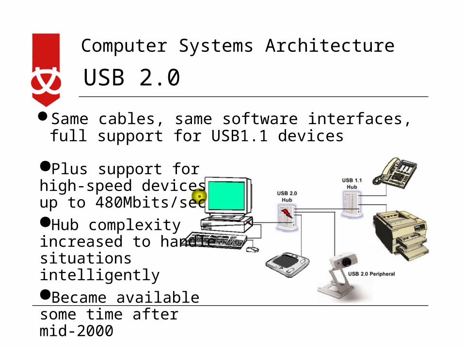
Same cables, same software interfaces, full support for USB1.1 devices
Plus support for high-speed devices up to 480Mbits/secHub complexity increased to handle situations intelligentlyBecame available some time after mid-2000

Computer Systems Architecture
USB Topology
Star- tiered topology
Supports up to 127 devices
Hot swappable
Plug and play capabilities
Host (Root Hub)
Hub 1 node node
Hub 2 node
Hub 3
Hub 4
node
node
node
node
Computer Systems Architecture
USB devices
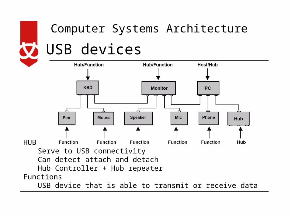
HUBServe to USB connectivityCan detect attach and detachHub Controller + Hub repeater
FunctionsUSB device that is able to transmit or receive data

Computer Systems Architecture
USB Cables
D+ and D- carry data signal
The signals on these two wires are referenced to the (third) GND wire
VBUS carries a nominal 5V power supply, which may be used by a device for power – up to 2.5 Watts.

Computer Systems Architecture
USB Cables
“A” receptacles point downstream from a Host or Hub, while "B" receptacles point upstream from a USB device or hub
A mini-B plug and receptacle-an alternative to B connector on handheld and portable devices
The mini-B has a fifth pin, named ID, but it is not connected
Computer Systems Architecture
Wireless USB
High speed personal wireless interconnect technology
Connects up to 127 devicesUp to 480Mbps at 3 metresUp to 110Mbps at 10 metresBased on the WiMedia Alliance “ultra-
wideband common radio platform”See http://www.usb.org/developers/wusb/docs

Computer Systems Architecture
USB 3.0 – added optical channel
Specifications released August 2008, chips by May 2009
USB 3.0 Promoters Group members:Intel, Microsoft, Hewlett-Packard, Texas Instruments, NEC and NXP Semiconductors
USB 3.0 products expected to arrive in 2009 or 2010About 5Gbps, copper connection, mostly backwards
compatible with USB2Originally intended to be part-optical, dropped due to
costsMore energy efficient than USB2

Computer Systems Architecture
USB On-The-Go
In standard USB, communication is controlled by the PC
There is no way to connect peripherals together without the PC
The USB On-The-Go (OTG) initiative specifies some additional capabilities to USB2.0
It adds some host capabilities to USB peripherals for direct interconnection
See http://www.usb.org/developers/onthego/USB_OTG_Intro.pdf

Computer Systems Architecture
Why USB?
Ease of use – relatively simple for the userBetter than existing connectors (2S/1P…)Single standard for manufacturers
Design time will be reduced after initial learning period, broadens market
Cost to manufacturers reduced by standardisation but raised by added complexity?
Changes to PC design are reducing internal expansion capability

Computer Systems Architecture
FireWire
Many motherboards come with IEEE1394 (a.k.a FireWire or i.Link) for DV camera connection
FireWire is a high performance, versatile LAN-style connector
Runs at about 400Mbps (similar to USB2)
Latest 800Mbps (2007)
Computer Systems Architecture
USB and FireWire Similarities
Many people confuse IEEE 394/FireWire/i.LINK and USB
Both are modern digital data connection technologies capable of linking multiple peripherals to a computer
Both permit “hot plugging” of peripherals (adding to or disconnecting from a computer without the need to reboot)
Both use thin, flexible cables which employ simple, durable connectors
Computer Systems Architecture
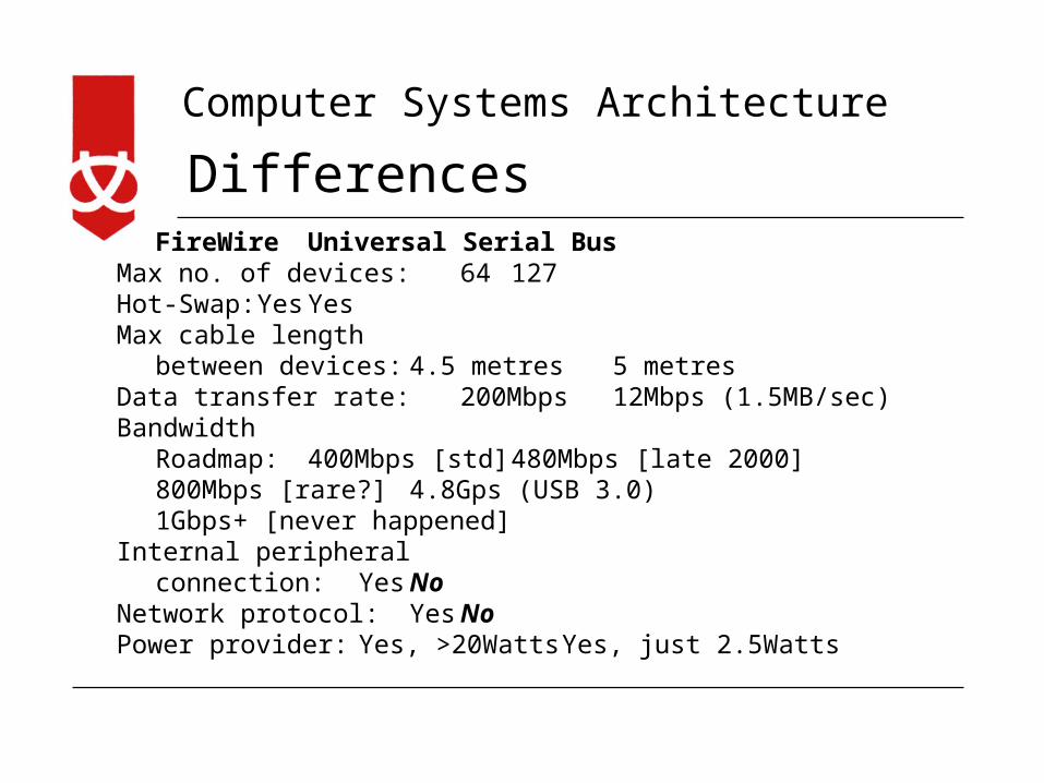
DifferencesFireWire Universal Serial Bus
Max no. of devices: 64 127 Hot-Swap: Yes YesMax cable length
between devices: 4.5 metres 5 metresData transfer rate: 200Mbps 12Mbps (1.5MB/sec)Bandwidth
Roadmap: 400Mbps [std] 480Mbps [late 2000]800Mbps [rare?] 4.8Gps (USB 3.0)1Gbps+ [never happened]
Internal peripheral connection: Yes No
Network protocol: Yes NoPower provider: Yes, >20Watts Yes, just 2.5Watts

Computer Systems Architecture
Original Target Markets
1394/FireWire/i.Link (200/400Mbps)
DV Camcorders
Professional High-Resolution Digital Cameras
Some HDTV applications
(HDTV?) Set-Top Boxes
Hard Disks
DVD-ROM Drives
Professional-level printers
Professional-level scanners
Universal Serial Bus (v1.1)
Keyboards
Mice
Monitors
Joysticks
Consumer Digital Cameras
Low-Speed CD-ROM Drives
Modems
Speakers
Consumer-level printers
Consumer-level scanners
Computer Systems Architecture
Different Markets and Approach• 1394 offers a data transfer rate that is many times faster
than USB1 and this was expected to continue, even with newer, faster versions of each technology
• But IEEE1394 development stalled…• Some industry commentators asked “Can IEEE1394 win
the interface war with USB?”• Most IT analysts expected IEEE1394 and USB to coexist
peacefully in modern computers• USB was expected to be reserved for lower-bandwidth
and less time-sensitive peripherals – but then came USB2• IEEE1394 is still used to connect to higher-bandwidth
electronics where guaranteed bandwidth is key

Computer Systems Architecture
What killed FireWire?
• Still not dead - IEEE1394 flourishes in niche areas of media communication
• But why the poor market penetration in personal computers?
• IEEE1394 is a fully developed networking protocol
• It is relatively complex and expensive
• Specialist markets don’t bring huge chip sales, so prices stay high
• It is “overkill” for most current PC applications
Computer Systems Architecture
SATA Serial Advanced Technology Attachment
• SATA is the current generation storage interface for PCs and low-end Servers
• The old Parallel ATA bus was not able to meet the increased bandwidth and performance demands of current and future PC designs
• This standard replaces the 40 pin ribbon connector with a small flexible signal cable
• SATA can be directly connected (hot plugged) to motherboards and back planes similar to current SCSI applications eliminating the need for cable completely
Computer Systems Architecture
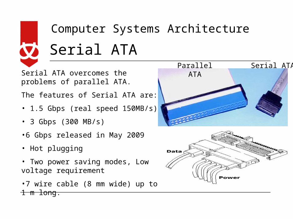
Serial ATA
Serial ATA overcomes the problems of parallel ATA.
The features of Serial ATA are:
• 1.5 Gbps (real speed 150MB/s)
• 3 Gbps (300 MB/s)
•6 Gbps released in May 2009
• Hot plugging
• Two power saving modes, Low voltage requirement
•7 wire cable (8 mm wide) up to 1 m long.
Serial ATAParallel ATA

Computer Systems Architecture
eSATA Port
External Serial Advanced Technology Attachment or eSATA is an external interface for SATA technologies.
Maximum cable length of 2 metres
eSATAp is a newer standard with provision for power to be supplied through data cables


![NATCO PHARMA LIMITED · Preliminary Placement Document Not for Circulation Private and Confidential Serial No. [ ] NATCO PHARMA LIMITED Originally incorporated as Natco Fine Pharmaceuticals](https://cdn.vdocuments.us/doc/165x107/5e931f04ea095c3dec7f16f1/natco-pharma-limited-preliminary-placement-document-not-for-circulation-private.jpg)
