
COMPUTER COMBUSTION-RADIA TION MODEL OF
RDF BOILERS A T COLUMBUS, OHIO •
DONALD A. KADUNC Alden E. Stilson & Associates
Columbus, Ohio
ROBERT H. ESSENHIGH The Ohio State University
Columbus, Ohio
ABSTRACT
A computer model based on the Columbus, Ohio RDF furnace system has been developed. The model simulates combusion and radiation heat transfers in the furnace. Variables evaluated were: Arrhenius combustion factors, turbulen t mixing factor, radiation Qlackening factor, air/fuel ratio, and Bragg stirred reactor height. Results provide design evaluation criteria.
SUMMARY
A computer program was developed to model the combustion behavior in stoker fired boil-ers [l] . The model is applicable to coal, bark, and refuse furnaces.
The model consists of a Bragg stirred reactor volume [2] followed by a plug flow volume. The latter volume is represented by a series of slices.
Combustion was modeled as a second order reaction proportional to fuel and oxygen concentrations. An Arrhenius rate constant [3] was included. The effects of frequency factor and activation energy were studied. The air/fuel ratio was varied. A bypass factor was theorized; this factor accounted for fuel residence time distribution and mixing behavior within volumes.
The size of the stirred reactor volume was a variable investigated.
The radiation heat transfer was modeled as a function of concentrations of H20 and CO2, and of particulates (flame blackening).
469
•
Results showed that it was not possible to distinguish the effects ·between frequency factor and activation energy. High frequency factor or low activation energy produced rapid burning, while opposite values retarded and in some cases stopped burning. The combustion appears to be highly insensitive to these factors individually; any attempt to experimentally isolate them will require extreme care.
Increasing the air/fuel ratio increased the combustion efficiency, but reduced the furnace temperatures and boiler efficiency. As the stirred reactor volume was increased, the combustion efficiency, peak furnace temperature, and boiler efficiency were reduced. In addition, the peak temperature shifted to higher in the furnace. Increasing bypass produced results similar to those due to larger stirred reactor volumes, except that peak furnace temperature was not necessarily reduced.
It was postulated that a relationship between stirred reactor volume and bypass existed. It was assumed that as the volume increased, the bypass would decrease. A function of these variables was developed and tested. As the volume was increased and bypass reduced, the peak temperature dropped and shifted higher in the furnace. The effects on combustion and boiler efficiency were inconclusive, but results indicate the two variables cancel each other (producing nearly constant values).
Blackening reduces combustion efficiency and temperature, but increases boiler efficiency. No peak temperature shift occurred.

BURNOUT ZONE
STIRRED REACTOR
ZONE
��� DELAY AREAS BYPASS ZONE
111111111 elva
PERFECT Y STIRRED ZONE L.I __ ---'
FIG. 1 PHYSICAL M O DEL
COMPUTER MODEL
A computer program was developed from a rather extensive mathematical model [1] of a stoker fired boiler. Figure 1 illustrates the model. A Bragg model [2] was used; this consists of a stirred reactor volume followed by a plug flow volume. A stirred reactor is a region of highly turbulent flow, which in most boilers is produced through the introduction of high velocity overfire jets. This volume has uniform properties (Le., constant temperature, pressure, composition). Delay areas were added to account for premixing in the bed and in the overfire jets. A plug flow volume is characterized as a fairly quiescent region with properties varying in Hie direction of flow. It is modeled as a series of thin slices with constant properties.
The fuel is an idealized hydrocarbon mixture containing Carbon, Hydrogen, Oxygen, water and ash. Nitrogen, Chlorine and Sulphur compounds may be included if pollution or corrosion studies pollution or corrosion studies are desired. In this paper the fuel composition is held constant and is patterned after normal municipal refuse.
Combustion is assumed to be a second order reaction proportional to the product of oxygen and fuel, where
k=Ae-Ea/RT sec-1
470
is the Arrhenius equation for the temperature (T, R *) reaction rate constant (k, sec�l) [3]. The frequency factor (A, sec -1) is a measure of the rate of molecular collisions and the activation energy (Ea' Btu/lb) indicates the critical energy that molecules must acquire before they can react. R(Btu/lb-F) is the gas constant.
Radiation heat transfer is .dependent on the local emissivities of CO2 and 'H20 in the gas stream. Hottel [4] provides values for these quantities dependent on temperature and concentration. A blackening factor, ala Beuters [4] is added to account for other gaseous and particulate emissions. The radiation from each slice interacts with all other slices and the walls of the furnace. Attenuation is dependent on the absorptivity of each slice, which is,a function of its temperature, and CO2-H20 concentration. The absorptivity of the walls is dependent on their surface properties.
Contained in the program are functional representations of all pertinent thermodynamic and heat transfer parameters. Most are temperature dependent. Also, in the program is a menu of design parameters (Le., boiler dimensions, fuel composition, preheat, exhaust gas recirculation, operating pressures, etc.) that may be changed to study their effects. All such parameters were assigned values in this study to represent a Columbus Ohio Municipal Electric Plant boiler operating at its full load design point.
The solution requires solving a set of temperature dependent, nonlinear equations using a Newton-Raphson iterative technique.
RESULTS AND DISCUSSION
Six parameters were studied to determine their effect on the combustion process within th� furnace. The parameters were frequency factor, activation energy, air/fuel ratio, bypass factor, stirred reactor height, and blackening factor.
Four of the parameters deal directly with the combustion process. The frequency factor and activation energy determine the reaction-rate velocity constant. The air/fuel ratio enters into the rate equation as information to calculate the air and fuel concentrations within that equation. The bypass factor enters the rate equation as a stirring coefficient.
The stirred reactor height provides a parameter to study the overall effect of geometry on the combustion process. The blackening factor provides a

parameter to study the influence of gas emissivity on heat transfer.
INPUT DATA
The dimensions of the furnace used were 18x 18x40 ft (S.SxS.SxI2 m) high which closely represent those of the Columbus boilers. Fuel composition was a simplified representation of refuse.
Fuel Characteristics
Carbon Hydrogen Oxygen H20 Ash Heat of Combustion Fuel I nput Rate
26 percent by weight 4 percent
20 percent 20 percent 20 percent 4,500 Btu/lb (3000 cal/kg) 50,000 Ib/hr (22,700 kg/hrl
The air and combustion gases were modeled as high temperature air with variable parameters of specific heat, conductivity, Prandtl number, and Reynolds number.
The range of frequency factors and activation energies was chosen to include the exp�rimental values determined by Biswas [6.06 x 10⁶ sec -1, 29,700 Btu/hr (16.S kcal)] 7 and Shieh [O.ISS x 106 sec-1, 3S,000 Btu/hr (20.1 kcal)] 8 . These are the only data available which approximates refuse fuel.
The bypass factor range is between zero and 1.0 with a base value of 0.3. No theoretical or experimental values have been established at this time which would limit this range.
The range of study of the blackening factor was from 1.0 to 3.0. Bueters was able to determine an experimental value for natural gas of about 1.2 and for oil of about 1.S.
The following base line figures were used during analysis.
Base Line Values
Activation Energy Frequency Factor Excess Air Bypass Stirred Reactor Ht. Blackening
32,000 Btu/hr (17,800 cal) 4X 1 06 sec-' 50 percent 30 percent 13 ft (4 m) 2.0
RESULTS-GENERAL CHARACTERISTICS
The aspects of most general interest required from the model, were the predictions of temperature and reactant-product proflles along the flow path of the furnace. The results obtained, which will be described in detail in later sections of this paper, are generally in accordance with what one
471
would expect in a furnace of this type. The temperature proflles match expectations; the fuel bUqlOUt and reaction products proflles are reasonable; however, the combustiqn efficiency appears to be slightly higher than expected. The thermal efficiency, nevertheless, is in the range that would be expected in such a boiler.
Figure 2 illustrates typical predictions; characteristically, two different types of temperature proflles are generated. Curve A shows a region of constant temperature through the stirred reactor region followed by a continuously decreasing temperature profile. In Curve B the stirred reactor constant temperature region is followed by a peaking temperature proflle (in each case the constant temperature is an artifact of the stirred reactor assumption that the properties throughout its volume are uniform).
The data also revealed two types of combustion proflles. As shown by Curve C of Fig. 3 one type of combustion was characterized by a step function. This was due to complete combustion occurring within a single slice. The second type of combustion profile is shown by Curve D. In this case combustion in the furnace takes place within a number of slices. The types of profiles are due to differences in reaction rates.
Two patterns of heat absorption occurred within the furnace. Curve E of Figure 3 shows a continu-
2600 2400 2200 2200 1800
HEIGHT o
...... -
F IG. 2 TYPICAL TEMPERATU RE PROF ILES
100%r---����------�� __ ---------' CURVE C _ - - - -COMBUSTION (cURVE 0
80 I ____ J
60
40
2 0
o o 10 20 30 40(FT.) BOILER HEIGHT
FIG. 3 COMB UST ION & A BSORPT ION PROF ILES

ously increasing function with a continuously decreasing slope. Curve F begins with a function of constant slope within the stirred reactor followed by a function similar to Curve E. The difference is due to the omission of a stirred reactor in the furnace, shown as Curve E.
FREQUENCY FACTOR AND ACTIVATION
ENERGY
Generally, (see Fig. 4) high activation energy and low frequency factor, combined, have the effect of generating poor combustion, and low activation energy combined with a high frequency factor has the effect of promoting good combustion.
Very different combinations of frequency factors and activation energies could all produce nearly identical results which implies that the combustion is somewhat insensitive to the reaction
3 ACTIVATION ENERGY x 10 (BTO/lB) 28 30 32 34 36
��\� /' � fr.O"- /' ��"" ./ /'
38
/'
2 �( I'" V V / �� /'" 'u IoJ 6 II) IXIO t II: e � 1
u 8 c( 5 IL 4.
5 IxlO
/
./ /' /
./ V
V /' / ,/
/
,.../
� ./ V / /
/ � /' /'
/' /./ �
�\o
/ �v
FIG. 4 F REQUENCY FACTOR VS ACTIVAT ION ENERGY
�O °r-----��----�------�----�� (oR) 2800
EXCESS AIR 2600 F-__ -=:25:...:%�
2400 t=-___ 5"'0::....: %=.J
2200 100%
2000 L-----------__ ----------------�
FIG. 5 EXCESS A I R TEMPERATURE PROF ILES
rates; evidently, it must be dominated by the heat transfer. It also means that determination of kinetic constants (Ea and A) from experimental data must be done with great care or the values can be subject to substantial error.
EFFECT OF AIR/FUEL RATIO
Figure 5 shows the temperature profiles in the furnace for fully developed combustion with differing excess air ratios. Increasing excess air substantially reduces the maximum furnace temperature. The temperature profile is also flattened out as the excess air is increased.
The effect of air/fuel ratio on combustion efficiency is illustrated in Fig. 6. One hundred percent air produced more complete combustion than 50 percent excess air. The rate equation is governed in part by the oxygen concentration and temperature of the gas. This higher concentration due to increased air would produce faster combustion other things being equal. However, the lower temperature offsets the oxygen differences and the two opposite effects do not totally cancel; the effect of higher oxygen concentration slightly overrides the effect due to lower temperature, and the run with the 100 percent excess air burns more completely than the run with 50 percent.
When runs of 100 percent and 25 percent are compared, however, the effects in the lower portion of the furnace are reversed; the effect of temperature dominates over that of oxygen concentration, and the run with 25 percent excess air burns faster than the run with 100 percent excess air. Nevertheless, in the upper portion of the furnace the effect of oxygen concentration again dominates over the effect of temperature and the run with the higher percentage of excess air burns faster and has a more complete burnout profile. From an environmental standpoint high excess air is beneficial.
Figure 6 also illustrates that as the excess air increases in a boiler the heat absorption rate decreases significantly. To increase the boiler operating efficiency, excess air should be minimized.
EFFECT OF BYPASS
It was felt that mixing and residence time distribution were overriding influences on combustion. A bypass factor was added to the combustion equation which forced combustion to take place over a large volume within the furnace. With-
472

80
60
40
20
o o
COMBUSTION
o o 0
• • •
• • • 0 0 '
• 0 o _ . . - -
0 0 -o -
o -o � 0 0 ....
. . � .-""" o --
10 20 BOILER HE IGHT
A8S0RPTION
30 401FT.)
FIG.6 EXCESS AIR COMBUSTION & ABSORPTION PROFILES
BOILER HEIGHT 0 10 20 30 40(FT.)
3000 ( " R) BYPASS 2800 0,..
10 % 2600
2400
2200 50%
2000 ...................................................................... ---
FIG.7 BYPASS FACTOR TEMPERATURE PROFILES •
out bypass, all the combustion takes place within the stirred reactor. As is shown in Fig. 8, when bypass is increased, combustion takes place over a larger volume of the furnace. The combustion rate is slowed as bypass is increased further. At 0.9, combustion in the furnace stops. This trend shows that poor mixing, as modeled by high bypass, slows the combustion rate and can even prevent combustion from taking place.
Figure 7 shows the effect of bypass on the temperature distribution within the furnace. Without bypass, the temperature declines as the gases move up the furnace. At low bypass (0.1) the temperature also declines a.s the gases move up the furnace,
bu t the slope of the curve is less than the curve without bypass. The maximum temperature, also, decreases.
As the bypass is increased to 0.3, the temperature profile no longer is declining. A hump develops in the profile. As the bypass is increased further to 0.5, the hump becomes more pronounced and the temperature peaks higher up in the furnace.
The figure also shows that increases in bypas� produce a reduction in combustion efficiency. This effect of reduced combustion efficiency is throughout the furnace even though bypass only directly effects the first few slices.
473
I
80
60
40
20
o
BYPASS
- - -__ - • ___ e . - • • r ._e- . . . . . . . / • ..-. 0 • 0 •
COMBUSTION ,. 30% I " , -----' I. •
I' �O% -: -.- . -.-.-.1 •
. -- - -70" - . -. -.
.,. . ...... - -._e - . . .
. . . . . . . - . - . . _... .- 70�
30% _.50% • • • .... _ . --' • • • • ABSORPTION - . -- . . - . •
o 10 20 30 40(FT.) BOILER HEIGHT
FIG.8 BYPASS COMBUSTION & ABSORPTION PROFILES
24 1200 22 20 • 1000 OXYGEN
o 18 � 16
FUEL ACTUAL 800 -;
.. 14 II) • ..J ... 12 -
� 10 600..J '"
- BYPASS '" z 8 ALONE 400 ... '" 6 � 4 )( 200 0 2
0 18 21 24 27 30 33 36 39 42(FT.)
BOILER HEIGHT
FIG.9 BURNUP PROFILES
In addition to reducing combustion efficiency bypass has a detrimental effect on the heat absorption rate within the furnace. This can be clearly seen in Fig. 8 where the heat absorption rate drops significantly as the bypass increases.
It is thought that bypass is to some extent a controllable parameter. Overfire air can be introduced into the furnace at a sufficient velocity and in such a pattern as to promote better mixing within the furnace. This leads directly to a stirred reactor design where violent mixing is promoted. The violent mixing speeds combustion and reduces bypass.
INTERACTIONS BETWEEN BYPASS,
FREQUENCY FACTOR AND ACTIVATION
ENERGY
A further analysis showed that the bypass only has an effect on the first few slices. After these slices, the frequency factor and activation energy retard the maximum burning rate in a slice as is shown by the higher fuel concentration in the latter slices than would be expected by bypass alone. Figure 9 shows a typical break point between the bypass and reactivity effects. The curve for bypass alone was computed on the basis of the expected geometrical decay pattern of fuel in the boiler.
The other curve was the actual result of a computer run showing the amount of fuel in the boiler

o 10 BOILER HEIGHT
20 30 40 (FT.l 3000 ,,---""'---"T'"---r---..,."'" (oR) 2800
2600
2400 ...... ---�
2200 �----------:::._:'-...:=_...J
2000 L.. _____________ ..;;;,,�
FIG. 10 STI RRED REACTOR HE IGHT TEMPE RATURE PROF ILES
at each slice. The difference in the two curves demonstrated that the burnout was affected by the frequency factor and activiation energy. The fuel burnup was similar in all runs. The fuel and oxygen profiles for a typical run are shown in the figure. It is seen that the oxygen profile is nearly flat. The slightly decreasing profile of the oxygen will asymptotically approach the value corresponding to the amount of excess air present in the system. At the same time the fuel will asymptotically approach zero as the furnace height is increased. The oxygen profile can be considered constant. This leads to the conclusion that the fuel burnup is a pseudo-first-order reaction. This can be taken as a quite general statement when a significant amount of excess air is present.
EFFECT OF STIRRED REACTOR HEIGHT
The boiler stirred reactor height was varied from zero to 40 ft (12 m). Figure 10 shows the change in furnace temperature profile as the stirred reactor height is increased. Increases in reactor height cause the heat to be generated in a larger volume. This leads to lower furnace temperatures. The temperature peak moves up the furnace as the stirred reactor height is increased.
Figure 11 also shows the effect the stirred reactor height has on combustion. When studied as a separate variable, increasing the stirred reactor height causes the combustion to be slowed. Larger stirred reactor volumes cause the furnace temperature to drop and these lower temperatures lead to the slower burning rates.
Figure 11 illustrates that larger stirred reactor volumes reduce the furnace heat absorption rate. Again, the larger stirred reactor volumes produce lower overall furnace temperatures. These lower furnace temperatures reduce the net amount of
80
60
40
20
'0 o 10 20 30 BOILER HEIGHT
40(FT.)
F IG. 11 STIRRED REACTOR HE IGHT COMBUST ION AND A BSORPTION PROFILES
heat transfer to the walls, which lowers the heat absorption rate.
INTERACTION BETWEEN BYPASS AND
STIRRED REACTOR HEIGHT
Increasing the stirred reactor height while holding bypass constant reduces the heat absorption rate. Increasing the bypass while holding the stirred reactor height constant reduces the heat absorption rate. One could intuitively reason that bypass will be large in shorter stirred reactor zones and approach zero as the stirred reactor height is increased to infinity. An attempt was made to study the combined effect of bypass and stirred reactor height. An arbitrary relation was made between bypass and stirred reactor height. This is shown in the table.
TABLE 1 HEAT UTIL IZAT ION RATE VS BYPASS A N D STI R RE D REACTOR HE IGHT
Stirred Reactor Heat Utilization Bypass Height, ft (m) Rate
0.7 7 (2) 0.398 0.5 13(4) 0.379 0.3 20(6) 0.383 0.1 30 (9) 0.398 0.0 40 (12) 0.403
No presumption is made that the correlation is realistic. It can be seen from the data that the effect of small bypass on the heat utilization rate appears to partially reverse the effect of large stirred reactor heights. Evidently, the two parameters tend to cancel each other out.
EFFECT OF BLACKENING FACTOR
The principal effects of blackening are to change the temperature profile in the furnace and to change the heat utilization rate.
474
30000� ____ -+ ____ �� ____ � ______ ��
(oR) 2800
2600
2400 F=====�� 2200
2oo0�----------------------------�
FIG. 12 BLACKEN ING FACTOR TEMPERATURE P ROF ILES
100')(, L---------:_�-i3-�-;S-iJ.E.E-i:. -E:. :;:"U�· !l� 80
60
40
20
o
COMBUST ION
3.0 BLACKENIN� • • • • • i.9
. . . :.---- ---
ABSORPTION
• • __ 1.0 • • !.--.-,-'
• • t-!':'''''
.�.-
o 10 20 30 40(FT.) BOILER HEIGHT
F IG. 13 BLACKEN ING FACTOR COMBUST ION & ABSORPT ION PROF ILES
By increasing the emissivity, blackening causes better heat transfer between the gas and the walls even though an increase in blackening causes a decrease in peak furnace temperature, as is seen in Fig. 12. It also causes a steeper decay in the temperature profIle.
Figure 13 shows the effect of the blackening factor on the combustion profIles. Blackening has little if any effect on combustion profIles. However, as is seen in the figure blackening has a large effect on the heat absorption ability of the furnace. High values of blackening produce much higher heat absorption rates than low values of blackening. It should be noted that increases in blackening cause reduced furnace temperatures as is shown in Fig. 12. This reduced temperature would reduce heat transfer to the walls causing lower heat absorption rates, but the opposite is actually occuring. So, the increase in emissivity caused by blackening greatly overshadows the reduction in furnace temperatures due to blackening, and this produces the large heat absorption rate.
EFFECT OF TEMPERATURE
The combustion process is highly dependent on temperature. The temperature of the gas enters the combustion equation as part of the exponen-
TEMPERAT URE (0 R) 1000 1400 1800 2200
! 100 r---r----r----.,r----..,--�-....;.;,.;..;;.
� 80 i= &.J � 60 � o 40 � � 20 ::;) III :I 8 o ... ;;;;;;;;;;;:;;;....--___ -=:::::;;;;;;= __ ...J
F IG. 14 PROF ILES OF COMBUST ION VS TEMPERATURE
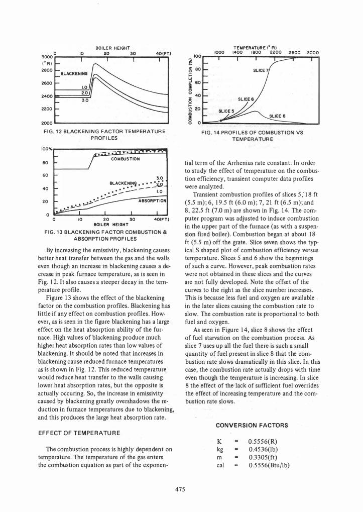
tial term of the Arrhenius rate constant. In order to study the effect of temperature on the combustion efficiency, transient computer data profiles were analyzed .
Transient combustion profIles of slices 5" 18 ft (5.5 m); 6,19.5 ft (6.0 m); 7,21 ft (6.5 m); and 8,22.5 ft (7.0 m) are shown in Fig. 14. The computer program was adjusted to induce combustion in the upper part of the furnace (as with a suspension fired boiler). Combustion began at about 18 ft (5.5 m) off the grate. Slice seven shows the typical S shaped plot of combustion efficiency versus temperature. Slices 5 and 6 show the beginnings of such a curve. However, peak combustion rates were not obtained in these slices and the curves are not fully developed. Note the offset of the curves to the right as the slice number increases. This is because less fuel and oxygen are available in the later slices causing the combustion rate to slow. The combustion rate is proportional to both fuel and oxygen.
475
As seen in Figure 14, slice 8 shows the effect of fuel starvation on the combustion process. As slice 7 uses up all the fuel there is such a small quantity of fuel present in slice 8 that the combustion rate slows dramatically in this slice. In this case, the combustion rate actually drops with time even though the temperature is increasing. In slice 8 the effect of the lack of sufficient fuel overrides the effect of increasing temperature and the combustion rate slows.
CONVERSION FACTORS
K kg m cal =
0.5556(R) 0.4536(lb) 0.3305(ft) 0.5556(Btu/lb)

REFERENCES
[1) Kadunc, D. A., Dissertation: "Computer Model of Combustion and Radiation Processes in Refuse Derived Fuel Fired Stoker Boilers," The Ohio State University, 1981; Available at: University Microfilms International, 300 N. Zeeb Road, Ann Arbor, Michigan 48106.
[2) Bragg, S. L., "Application of Reaction Rate Theory to Combustion Chamber Analysis," Aeronautical Research Council Paper No. 16170, C.F. 272, September 1953.
[3) Glassman, I., Combustion, Academic Press, New York, N.Y., 1977.
[4) Hottel, H. C. and Sarofim, A. F., Radiative Transfer, McGraw-Hili, New York, 1967.
[5) Bueters, "Combustion Products Emissivity by Fc Operator," Combustion, March 1974.
[6) Bueters, K. A., Cogoli, J. G., and Habelt, W. W., "Performance Prediction of Tangentially Fired Utility Furnaces by Computer Model," 15th International Symposium on Combustion, Tokyo, Japan, August 25-31, 1974.
(7) Biswas, B. K. and Essenhigh, R. H., "The Problem of Smoke Formation and Control," Paper No. 39f presented at A.1. Chem.E. 70th National Meeting, Atlantic City, Aug/Sept., 1971.
[8) Shieh, W. and Essenhigh, R. H., "Combustion of Computer Cards in a Continuous Test Incinerator: A Comparison of Theory and Experiment," Proceedings of 1972 National Incinerator Conference, ASME' New York, 1972, pp. 120-134.
Key Words Boiler
Coal
Columbus
'Combustion
Pollution
Refuse-Derived Fuel
Stoker
476


