Compton polarimetry for EICJefferson Lab Compton Polarimeters
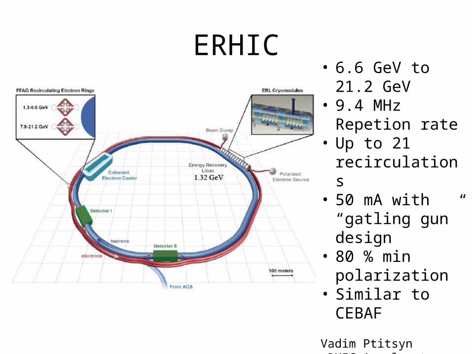
ERHIC• 6.6 GeV to 21.2
GeV • 9.4 MHz Repetion
rate• Up to 21
recirculations• 50 mA with
“gatling gun” design
• 80 % min polarization
• Similar to CEBAF
Vadim PtitsyneRHIC Accelerator DesignEIC2014

MEIC
• Storage ring – Ring ring• 748.5 MHz = 1.33 ns bunch
structure• 3 A at 3 GeV and 180 mA at 11
GeV• 2 macrobunch with one
polarization 2.3 us• Measure polarization average
of the two macrobunch• Every electron bunch crosses
every ion bunch
Warm large booster(up to 25 GeV/c)
Warm 3-12 GeV electron collider ring
Medium-energy IPs withhorizontal beam crossing
Injector
12 GeV CEBAF
Pre-boosterSRF linac Ion
source
Cold 25-100 GeV/cproton collider ring
Three Figure-8 rings stacked vertically
Electron cooling

Compton asymmetrye + g e’ + g’
s( ) e + g e’ + g’
s( )
)

Hall A Compton chicane

Cavity power
• Green laser using IR seed laser and PPLN frequency doubling
• Around 5 kW power
• 10 kW reachable
• Lazer polarization flip
• Abdurahim Rakhman (2011) Phd Thesis Syracuse

Hall A Photon detector • FADC readout SIS3320 250 MHz FADC• Digital integration with 240 Hz helicity flip• Record
all thesignalfor a givenhelicity
• Compute integratedasymmetryfor a pair

Happex III resultsFriendNucl.Instrum.Meth. A676 (2012) 96-105
Friend Phd Thesis CMU 2012
Pe =89.41%

Hall C Compton Electron DetectorDiamond microstrips used to detect scattered electrons Radiation hard Four 21mm x 21mm planes each with 96 horizontal 200 μm wide micro-strips. Rough-tracking based/coincidence trigger suppresses backgrounds
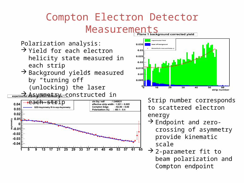
Compton Electron Detector Measurements
Polarization analysis: Yield for each electron helicity state
measured in each strip Background yields measured by
“turning off” (unlocking) the laser Asymmetry constructed in each strip
Strip number corresponds to scattered electron energy Endpoint and zero-crossing of
asymmetry provide kinematic scale
2-parameter fit to beam polarization and Compton endpoint

Polarization MeasurementsQ-Weak Run 2 – November 2011 to May 2012
PMoller +/- stat (inner) +/- point-to-point systematic (0.54%)
PCompton +/- stat +/- preliminary systematic (0.6%)
Photocathode re-activation
0.64% normalization unc. not shown
Preliminary

Preliminary Systematic UncertaintiesSystematic Uncertainty Uncertainty ΔP/P (%)
Laser Polarization 0.1% 0.1Dipole field strength (0.0011 T) 0.02
Beam energy 1 MeV 0.09Detector Longitudinal Position 1 mm 0.03
Detector Rotation (pitch) 1 degree 0.04Asymmetry time averaging 0.15% 0.15%
Asymmetry fit 0.3% 0.3%DAQ – dead time, eff. Under study ??
Systematic uncertainties still under investigation, but final precision expected to be better than 1% DA- related systematics likely the most significant remaining issue to study

Simulation background
BremstrahlungHalo
• 1 kW green laser• 1 A• 3 GeV electron
beam
• Halo contribution modeled on PEP II
Photon detector signal
Electron detector signal

Compton polarimeter in low-Q2 chicane
Same polarization as at the IP due to zero net bend
Non-invasive continuous polarization monitoring
Polarization measurement accuracy of ~1% expected
No interference with quasi real photon tagging detectors
c
Laser + Fabry Perot cavity
e- beam
Quasi-real high-energy photon tagger
Quasi-real low-energy photon tagger
Electrontracking detector
Photon calorimeter
Possible implementation in low Q2
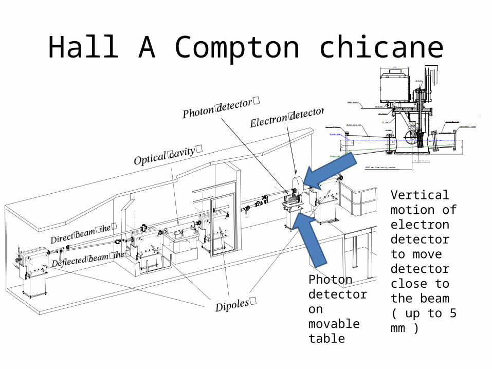
Hall A Compton chicane
Vertical motion of electron detector to move detector close to the beam( up to 5 mm )Photon
detector on movable table

Conclusion
• Compton polarimetry at 1% level achieved at Jefferson Laboratory and aiming at 0.5 % for 12 GeV parity program
• Jefferson Lab ideal ground for Compton testing for EIC since Compton is non invasive– Photon detector testing straight forward– Electron detector testing doable with planning
because of vacuum. Looking into Roman pot option for ease of detector swapping


