
COMPONENTS AND
REPAIR MANUAL
MODEL MCL 36/42C
EARTH BORING MACHINEPART NO. 3620000
MACHINE SERIAL NO.:
3642C 122713 34 & LATER
MANUAL PART NO.: E250155
2006 Perimeter Rd. Greenville, SC 29605
Toll Free: 800-435-9340 - Phone: 864-277-5870
Fax: 864-235-9661 - www.mightymole.com
email: [email protected]
Machine Serial #_________________________________________________________
Purchased &
Serviced Thru: __________________________________________________________
Purchase Date: _________________________________________________________
© 2014 by McLaughlin Group, Inc. All rights reserved. No part of this manual
may be reproduced in any form or by any means without prior written permission from the
McLaughlin Group, Inc.. Revision Date: 10.15.14

WARNING: Battery posts, terminals and releated accessories contain lead and lead
compounds, chemicals known to the State of California to cause cancer and birth
defects or other reproductive harm. Wash hands after handling.
WARNING: The engine exhaust from this product contains chemicals
known to the State of California to cause cancer and birth defects or other
reproductive harm.

DESCRIPTION PAGE
Machine Specifications and System Operating Specifications 1.1.0
Fill Points, Filters and Routine Maintenance 2.1.0
Decal Placement 2.2.0
Machine Assemblies, Parts Details 3.0
Carriage Assembly 3.1.0
Roll Bar Assembly 3.2.0
Powertrain Assembly 3.3.0
Dog Plate Assembly 3.4.0
Casing Pusher Assembly & Adapters 3.5.0
Master Track Assembly 3.6.0
Engine Exhaust System 3.7.0
Hydraulic Tank Assembly 3.8.0
Hydraulic Cylinder 3.9.0
Hydraulic Pump Seal Kit 3.10.0
Hydraulic Pump Coupling 3.11.0
Replacement Disk Kit 3.12.0
Clutch Seal Kit 3.13.0
Clutch Bearing Kit 3.14.0
Machine Operating Systems 4.0
Hydraulic System and Components 4.1.0
Electrical System (Wiring Diagram) 4.2.0
Machine Parts and Repair 5.0
Engine (Operation and Parts) 5.1.0-5.1.38
Transmission (Parts) 5.2.0
Gearbox (Parts) 5.3.0
Hydraulic Pump Coupling 5.4.0
Clutch 5.5.0
Hydraulic Thrust Cylinder 5.6.0
Hydraulic Dog Plate Cylinder 5.7.0
Hydraulic Valve (Parts) 5.8.0
McL 36/42C
McLaughlin Boring Systems reserves the right to make changes at any time without notice or obligation.
TABLE OF CONTENTS
MACHINE SPECIFICATIONSMcL 36/42C
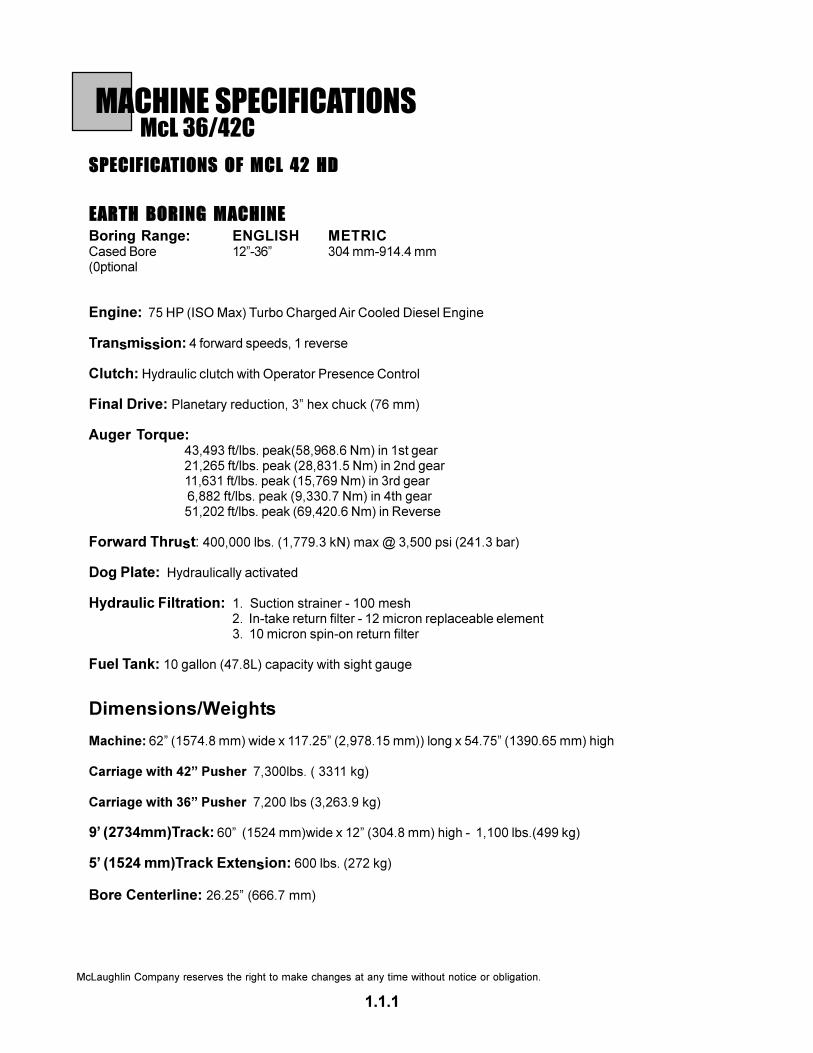
SPECIFICATIONS OF MCL 42 HD
EARTH BORING MACHINE
Boring Range: ENGLISH METRICCased Bore 12”-36” 304 mm-914.4 mm(0ptional
Engine: 75 HP (ISO Max) Turbo Charged Air Cooled Diesel Engine
Transmission: 4 forward speeds, 1 reverse
Clutch: Hydraulic clutch with Operator Presence Control
Final Drive: Planetary reduction, 3” hex chuck (76 mm)
Auger Torque:43,493 ft/lbs. peak(58,968.6 Nm) in 1st gear21,265 ft/lbs. peak (28,831.5 Nm) in 2nd gear11,631 ft/lbs. peak (15,769 Nm) in 3rd gear 6,882 ft/lbs. peak (9,330.7 Nm) in 4th gear51,202 ft/lbs. peak (69,420.6 Nm) in Reverse
Forward Thrust: 400,000 lbs. (1,779.3 kN) max @ 3,500 psi (241.3 bar)
Dog Plate: Hydraulically activated
Hydraulic Filtration: 1. Suction strainer - 100 mesh2. In-take return filter - 12 micron replaceable element3. 10 micron spin-on return filter
Fuel Tank: 10 gallon (47.8L) capacity with sight gauge
Dimensions/Weights
Machine: 62” (1574.8 mm) wide x 117.25” (2,978.15 mm)) long x 54.75” (1390.65 mm) high
Carriage with 42” Pusher 7,300lbs. ( 3311 kg)
Carriage with 36” Pusher 7,200 lbs (3,263.9 kg)
9’ (2734mm)Track: 60” (1524 mm)wide x 12” (304.8 mm) high - 1,100 lbs.(499 kg)
5’ (1524 mm)Track Extension: 600 lbs. (272 kg)
Bore Centerline: 26.25” (666.7 mm)
1.1.1
McLaughlin Company reserves the right to make changes at any time without notice or obligation.

SYSTEM OPERATION SPECIFICATIONSMcL 36/42C
Engine
1. Speed Idle: 1050-1150 Max.: 2400-2500
2. Oil SAE 5W-30 or refer to manual section 5.0
3. Fuel Commercially available diesel fuel with less than
0.5% sulphur content. Refer to manual section 5.0.
4. Fuel Tank Capacity ~ 15 Gallons (56 l.)
Gearbox 80-90 wt. gear oil with EP additives
Capacity ~ 4.68 qts (4.44 l)
Transmission Synthetic 50 wt. transmission fluid
Capacity 6.2 qts (5.9 l)
Hydraulic System
1 Hydraulic Pump Pressure Compensated w/ Load Sense
Compensator Setting: ~ 5000 psi
Stand-by Setting: ~ 250-300 psi
2. Hydraulic Control Valve Electric-proportional w/ Manual operation
Main Thrust Sysem Relief Valve Setting: ~ 5100 + psi
3. Hydraulic Control Valve Dog Plate Spool Relief Valve
Secondary System Setting: ~ 500 psi
4. Hydraulic Fluid: 76 Unax AW #46 or equivalent
ISO grade 46, hydraulic fluid with anti-wear additives. Contains
additives that provide oxidation resistance, rust and corrosion
protection, foaming resistance and have water separating
characteristics. Consult McLaughlin Manufacturing Co. for
recommendations on cold weather operation.
5. Hydraulic Tank Capacity ~ 60 Gallons (225 l.)
Electrical System
1. Battery 12V DC w/ 700 CCA Max.
2. Hydraulic Control Valve 12V DC w/ Electric Solenoid
Main Thrust System
3. Preheat System 12 V DC w/ manual delay
4. Fuses 12V DC, Inline and panel, SFE and ATO styles
5. Cartridge Valves 12V DC at 1-3 Amps
*Specifications subject to change without notice or obligation.
1.1.2

FILTERS AND FILL POINTSMcL 36/42C
1. Engine Oil Fill - Use only manufacturer’s
approved oils (Reference section 5.1 Engine
Operation).
3. Oil Filter - Use only manufacturer approved
engine filter. Reference section 5.1 Engine
Operations for specifications and maintenance.
2. Dip Stick - Check daily with engine warm.
Fill as needed to the upper dash mark on the stick.
4. Fuel Filter - Use only manufacturer’s approved
replacement filters. (Reference section 5.1 Engine
Operation for maintenence schedule).
5. Fuel Level - Fill as needed with branded
grades of diesel fuel with a sulfur content below
0.5% (Reference section 5.0 Engine Operation for
approved fuel specifications).
2.1.1
1
2
3, 4
5

FILTERS AND FILL POINTSMcL 36/42C
7. Hydraulic Oil Filter - Replace all filters
with every engine oil change or if required by filter
indicator, whichever comes first. Clean or replace
in-tank suction strainer annually when oil is
changed.
9. Transmission Oil Fill - Fill to check
point with #50 synthetic transmission fluid.
Change after first 50 hours of use, then every
1000 hours or annually. Drain.
8. Gearbox Oil Fill - Fill to check point.
Change after first 50 hours of use, then every
1000 hours or annually.
6. Hydraulic Oil Level - Fill to 1 1/2” below top
of tank (with cylinders retracted). Change oil after
first 1000 hours of use, then annually.
2.1.2
6
7
8
9
10. Engine Air Cleaner - Check air cleaner
element condition using the filter indicator.
Clean or replace element when indicator is in the
“red zone.” Clean or replace when required
by the filter indicator or annually, which ever
comes first. Reference pages 5.1.25 & 5.1.26 of
the Engine Operation section for more information.

DEC
AL P
LAC
EMEN
TM
cL 3
6/4
2C
2.2
.1
DE
CA
L A
PP
LIC
AT
ION
:
RE
MO
VE
OIL
AN
D D
IRT
FR
OM
SU
RFA
CE
.
MA
KE
SU
RE
SU
RF
AC
E IS
SM
OO
TH
.
J000100 - DANGER
ENTANGLEMENT HAZARD
J800030 - INSTRUCTION
OPERATOR’S MANUALJ000080 - WARNING
DO NOT GO FORWARD
J000020 - WARNING
AVOID DEATH
J000210 - WARNING
LOCATE UTILITIES

DEC
AL P
LAC
EMEN
TM
cL 3
6/4
2C
2.2
.2
J000080 - WARNING
DO NOT GO FORWARD
J000200 - DANGER
MACHINE PARTSJ000120 - DANGER
ROTATING BLADES
J000160 - WARNING
PINCH POINT
2 REQUIRED
J802000 - WARNING
ROTATING SHAFT

CARRIAGE ASSEMBLYMcL 36/42C
3.1.1

CARRIAGE ASSEMBLYMcL 36/42C
3.1.2
#METI .YTQ REBMUN NOITPIRCSED1 1 1010263 egairraC2 1 0510263 knaTleuF
1 128000U "52.1X31-2/1CH,wercS2 068000U "57.1X31-2/1CH,wercS3 021021U 31-2/1kcoL,tuN
3 4 3110263 nwoDdloH4 2510263 niPnwoDdloH4 040023U rettoC,niP4 7010263 niPkcoLnwoDdloH4 571007R pilC-R,niP4 080000W leehW4 075100U "00.5X8-1CH,wercS4 071002U .D.O"2/12X"1talF,rehsaW
4 1 5010063 nwoDdloHyrettaB2 002021U 61-8/3egnalF,tuN1 9110263 tsoPgnirpSekarBtooF1 050016U gnirpS
5 1 020004X V21,yrettaB6 1 8010263 mroftalProtarepO
2 030100U "0.6X31-2/1CH,wercS2 021021U 31-2/1kcoL,tuN
7 1 6600042 tekcarBtooF2 128000U "52.1X31-2/1CH,wercS2 111012U 2/1kcoL,rehsaW1 8500042 tnemtsujdAekarB1 080005T gnittiFesaerG1 9500042 ekarBkcarT1 020061U "01-4/3maJ,tuN1 040022U "4/3ratS,rehsaW1 3500042 ladePtooFekarB1 062100U "52.3X11-8/5CH,wercS1 020021U 11-8/5kcolyN,tuN

ROLL BAR ASSEMBLYMcL 36/42C
3.2.1

ROLL BAR ASSEMBLYMcL 36/42C
3.2.2
#METI .YTQ REBMUN NOITPIRCSED
1 1 1010263 egaClloR
8 098000U 8G"00.2X31-2/1CH,wercS
8 111012U "2/1kcoL,rehsaW
8 568000U 8G"57.1X31-2/1CH,wercS
8 021021U 31-2/1xeH,tuN
4 024100U "05.2X01-4/3CH,wercS
4 040021U 01-4/3kcolyN,tuN
2 1 3220263 etalPtnuoMretliFriA
2 002000U "00.1X81-61/5CH,wercS
2 021021U 31-2/1kcoL,tuN
3 1 2070263 knaTciluardyH
4 2670084 rotalosIknaTciluardyH
8 002021U 61-8/3egnalF,tuN
4 1 7110263 tfeLtnuoMknaTciluardyH
4 048000U "05.1X31-2/1CH,wercS
4 001002U "2/1talF,rehsaW
4 021021U 31-2/1kcoL,tuN
5 1 8110263 thgiRtnuoMknaTciluardyH
4 048000U "05.1X31-2/1CH,wercS
4 001002U "2/1talF,rehsaW
4 021021U 31-2/1kcoL,tuN
6 1 1080263 xoBelosnoC
4 040000U "57.X02-4/1CH,wercS
4 001021U 02-4/1kcoL,tuN
7 1 7120263 revoCelosnoC
4 081000U "57.X81-61/5CH,wercS
4 040011U 81-61/5kcolyN,tuN
8 1 0170263 eldnaHevlaVtnuoMpirG
1 500124T elppiNesolC"8/3
1 6170184 retpadApirG
1 0180084 hctiwShtiwpirG
9 1 3020063 sniPhtiweldnaHevlaV
01 1 6110063 lortnoCelttorhT
1 5110063 elbaCelttorhT
1 1310063 retpadAdaeHkluBelbaCelttorhT
1 7700042 tekcarBelbaCelttorhT
1 020002U "4/1talF,rehsaW
11 1 6900063 evlaV
4 064000U "05.1X61-8/3CH,wercS
21 1 4220263 etalPeguaG
2 29000DH eguaGerusserP
2 081000U "57.X81-61/5
2 040011U 61-8/3kcolyN,tuN

POWERTRAIN ASSEMBLYMcL 36/42C
3.3.1

3.3.2
POWERTRAIN ASSEMBLY
McL 36/42C
ITEM QTY PART # DESCRIPTION
1 1 3620510 3” CHUCK
12 U001465 SCREW, HC 3/4”-10 X 3.25” ZP G8
12 U210160 WASHER, LOCK 3/4”
2 1 3620302 GEAR HUB ADAPTER RING
16 U001420 SCREW, HC 3/4”-10 X 2.50” ZP G5
16 U210160 WASHER, LOCK 3/4”
3 1 3620303 GEARBOX SEAL PLATE
4 U030130 SCREW, SFH 1/2”-13 X 1.00
4 1 W200180 O-RING
5 1 3620301 GEAR HUB
16 U001420 SCREW, HC 3/4”-10 X 2.50” ZP G5
16 U210160 WASHER, LOCK 3/4”
6 1 P340000 INPUT ADAPTER
1 U410140 KEY, 3/8” SQ X 1.50”
4 U000840 SCREW, HC 1/2”-13 X 1.50”
4 U210100 WASHER, LOCK 1/2”
7 1 P260200 COUPLING CENTER MEMBER
2 U001320 SCREW, HC 5/8”-11 X 4.00”
2 U210140 NUT, LOCK 5/8”
8 1 P260210 COUPLING CENTER MEMBER
2 U001280 SCREW, HC 5/8”-11 X 3.50”
2 U210140 WASHER, LOCK 5/8”
9 1 3600070 COUPLING ADAPTER PLATE
4 U000760 SCREW, HC 7/16”-14 X 1.25”
4 U210080 WASHER, LOCK 7/16”
10 1 3620333 COUPLING GUARD ASSEMBLY
3620325 BASE SHIELD
3620330 EXTENSION SHIELD
4 U000420 SCREW, HC 3/8”-16 X 1.00”
4 U210060 WASHER, LOCK 3/8”
4 U100060 NUT, HEX 3/8”
11 1 3620140 ENGINE/TRANSMISSION MOUNT ASSEMBLY
1 3620136 ENGINE MOUNT
4 U001660 SCREW, HC 14MM X 2.0 X 50MM
4 U210120 WASHER, LOCK 14MM
1 3620142 TRANSMISSION MOUNT
4 U000840 SCREW, HC 1/2”-13 X 1.50”
4 U210100 WASHER, LOCK 1/2”
4 U200100 WASHER, FLAT 1/2”
2 U000540 SCREW, HC 3/8”-16 X 2.50”
2 U200040 WASHER, LOCK 5/18”
12 1 3620319 OIL PUMP MOUNT BRACKET
4 U000425 SCREW, HC 3/8”-16 X 1.00”
4 U210060 WASHER, LOCK 3/8”
4 U200600 WASHER, FLAT 3/8”
1 3620320 OIL PUMP
4 U000020 SCREW, HC 1/4”-20 X .50”
4 U200020 WASHER, FLAT 1/4”
4 U210020 WASHER, LOCK 1/4”
13 1 3600132 COMPANION FLANGE
14 1 3600117 BEARING RETAINER
15 1 3600114 TRANSMISSION
16 1 P230020 BELL HOUSING
12 U001620 SCREW, HC 10MM X .50” X 25MM
12 U210222 WASHER, LOCK 10MM
1 T400391 BULKHEAD ADAPTER
1 3600141 INSPECTION PLATE
2 U000160 SCREW, HC 5/16-18 X .50”
2 U200040 WASHER, LOCK 5/16”
ITEM QTY PART # DESCRIPTION
17 1 3600210 HYDRAULIC CLUTCH
1 TH00093 HYDRAULIC HOSE
1 T401101 ELBOW, 90DEG
18 1 3600211 DRIVE SHELL
6 U010305 SCREW, HSH 8MM X 1.25 X 30MM
6 U210350 WASHER, LOCK 8MM HIGH COLLAR
19 1 3600277 CLUTCH SPACER
20 1 W300060 TAILSHAFT BEARING
21 1 3620304 HEAT EXCHANGER
2 U000040 SCREW, HC 1/4”-20 X .75”
2 U200020 WASHER, FLAT 1/4”
2 U210060 WASHER, LOCK 1/4”
22 1 3620305 HEAT EXCHANGER MOUNTING BRACKET
14 U001620 SCREW,HC 10MM - 1.50” X 25MM
2 U210222 WASHER, LOCK 10MM
23 1 3620802 HEAT EXCHANGE FAN
24 1 3600091 ENGINE, DUETZ
25 1 3620161 PUMP ADAPTER WELDMENT
4 U001195 SCREW, HC 5/8”-11 X 1.75”
4 U210140 WASHER, LOCK 5/8”
27 1 CM00010 HYDRAULIC PUMP
2 U000860 SCREW, HC 1/2”-13 X 1.75”
2 U210100 WASHER, LOCK 1/2”
2 U200110 WASHER, FLAT 1/2” SAE HARDENED
28 1 3620130 ENGINE MOUNT BRACKET
6 U001645 SCREW, HSH 14MM X 2.0 X 45MM GR12.9
6 U210115 WASHER, FLAT 9/16” SAE HARDENED
29 4 3600086 ENGINE ISOLATOR
4 3600089 SNUBBLING WASHER
4 U000960 SCREW, HC 1/2”-13 X 4.00”
4 U200110 WASHER, FLAT 1/2” SAE HARDENED
4 U120120 NUT, LOCK 1/2”-13
* 1 3620160 PUMP SHAFT HUB
* NOT SHOWN

DOG PLATE ASSEMBLYMcL 36/42C
3.4.1

DOG PLATE ASSEMBLYMcL 36/42C
3.4.2
#METI .YTQ REBMUN NOITPIRCSED1 1 5600063 etalPgoD2 3 7700063 niPrednilyC3 2 4600063 niPgoD4 2 040420U "05.X31-2/1teS,wercS5 2 060006U gnirpSnioisserpmoC6 1 4210063 rednilyCciluardyH
2 089000U "00.4X31-2/1CH,wercS7 1 2210063 drauGrednilyC
2 001002U "2/1talF,rehsaW2 111012U "2/1kcoL,rehsaW2 018000U "57.X31-2/1CH,wercS

36” CASING PUSHER/SPOIL EJECTOR
3.5.1
McL 36/42C
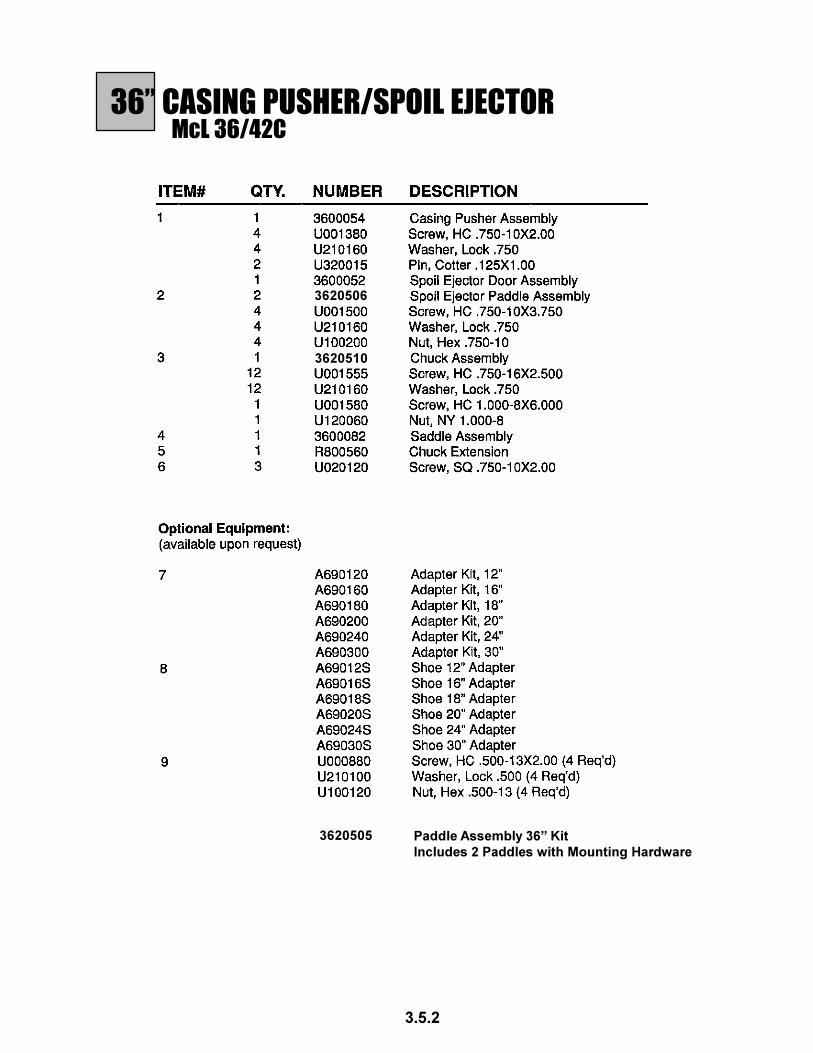
36” CASING PUSHER/SPOIL EJECTORMcL 36/42C
3.5.2
3620505
3620506
3620510
Paddle Assembly 36” Kit
Includes 2 Paddles with Mounting Hardware

42” CASING PUSHER/SPOIL EJECTORMcL 36/42C
3.5.3

42” CASING PUSHER/SPOIL EJECTORMcL 36/42C
3.5.4
3620510
3620502
3620501 Paddle Assembly 42” Kit
Includes 2 Paddles with Mounting Hardware

MASTER TRACK ASSEMBLYMcL 36/42C
3.6.1

MASTER TRACK ASSEMBLYMcL 36/42C
3.6.2
ITEM # QTY NUMBER DESCRIPTION
1 3 3620601 9 FT Track
2 1 3620615 5 FT Track Extension
3 1 3620611 Push Plate
4 32 U001420 Screw, HC 3/4-10 x 2.50 Lg
5 8 U001440 Screw, HC 3/4-10 x 3.00 Lg
6 40 U100200 Nut, Hex, 3/4-10
7 40 U210160 Washer, Flat 3/4”

ENGINE EXHAUST SYSTEMMcL 36/42C
McL 36/42C
3.7.1
#METI .YTQ REBMUN NOITPIRCSED1 1 7400024 ylbmessAepiPtsuahxE
3 072001U 52.1Xmm8xeH,tuN
3 550012U mm8kcoL,rehsaW2 1 6400024 ylbmessArelffuM
1 095100U mm51X52.1Xmm8CH,wercS1 021008U "00.2pmalC-U
3 1 2500024 ebuTekatnIriA1 070008U "00.3dnaB,pmalC
4 1 2400024 woblE1 1400024 rotacidnIretliFriA
5 1 2620063 etelpmoCrenaelCriA1 0620063 tnemelEtnemecalpeR1 1620063 tnemelEytefaS1 8620063 evlaVegrahcsiDriA
6 1 2400024 woblE
1
2
3
4
5
6
ENGINE EXHAUST SYSTEM

McL 36/42C
McL 36/42C
3.8.1
HYDRAULIC TANK ASSEMBLY
#METI .YTQ REBMUN NOITPIRCSED1 1 3070263 knaTciluardyH2 4 8070263 tnuoMtooF
8 518000U 5GPZ0.1X31-2/1CH,wercS8 111012U kcoL,rehsaW
3 1 021027T eguaGthgiS4 2 8570084 revoCtuOnaelC5 2 051504T CHTPN"4/1,gulP6 1 1670084 reniartSnoitcuS7 1 8600502 paClliF
HYDRAULIC TANK ASSEMBLY

HYDRAULIC CYLINDERMcL 36/42C
McL 36/42C
#METI .YTQ REBMUN NOITPIRCSED6-1 *1 7510063 :sedulcnItiKlaeS
gniR-O)1(-1pu-kcaB)1(-2
repiW)1(-3puC-U)1(-4gniR-O)1(-5puC-U)2(-6
7 *1 1610063 niPsivelC8 *2 2610063 niPpilC9 *1 7710063 paCdaeHgniRgniniateR01 *1 8710063 ylbmessAdoR
rednilyCreP*
3.09.1
HYDRAULIC CYLINDER

HYDRAULIC PUMP SEAL KITMcL 36/42C
McL 36/42C
#METI .YTQ REBMUN NOITPIRCSED1 1 1020063 tiKlaeS
:sedulcnItiKlaeStfahS)1(sgniRlaeS)1(sgniRteS-U)6(
sgulP)2(sgniR-O)22(*
.snoitarugifnocpmupllarofdedulcnierasgniR-O:etoN*.noitarugifnoctnerrucotdehctamebtsumsgniR-O
3.10.1
HYDRAULIC PUMP SEAL KIT

HYDRAULIC PUMP COUPLINGMcL 36/42C
McL 36/42C
#METI .YTQ REBMUN NOITPIRCSED1 1 9510063 buHgnilpuoC2 1 1210042 eveelSnolyN3 1 6510042 buHyelluP4 1 2210042 egnalFyelluP
3.11.1
HYDRAULIC PUMP COUPLING

REPLACEMENT DISK KITMcL 36/42C
McL 36/42C
3.12.1
REPLACEMENT DISK KIT
ITEM # QTY NUMBER DESCRIPTION
1 1 3600220 Kit Includes:
6 63 Tooth Gear Disks
5 Spacer Plates
6 Belleville Springs
1 circular Clip

CLUTCH SEAL KITMcL 36/42C
McL 36/42C
3.13.1
CLUTCH SEAL KIT
ITEM # QTY NUMBER DESCRIPTION
1 1 3600221 Kit Includes:
1 Small O-Ring
1 Large O-Ring
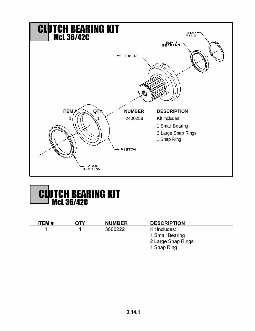
CLUTCH BEARING KITMcL 36/42C
McL 36/42C
#METI .YTQ REBMUN NOITPIRCSED1 1 8520042 :sedulcnItiK
gniraeBllamS1
sgniRpanSegraL2gniRpanS1
3.14.1
CLUTCH BEARING KIT
ITEM # QTY NUMBER DESCRIPTION
1 1 3600222 Kit Includes:
1 Small Bearing
2 Large Snap Rings
1 Snap Ring

HYDRAULIC SYSTEMMcL 36/42C
4.1.1
HOSES AND FITTINGS

HY
DR
AU
LIC S
YS
TEM
Mc
L 36
/42
CH
OS
ES A
ND
FITT
ING
S
4.1
.2
NOTE: For replacement Hose Assemblies,
please include hose length and end fittings.
Hydraulic Components
# Placement
1 Hydraulic Tank 6320702
2 Pressure Reducing Valve 3600119
3 Screen Filter N/A
4 Gauge 4800784
5 Return Filter T700100
6 Control Valve 3620720
7 Dog Plate Cylinder 3600124
8 Hydraulic Pump CM00420
9 Fast Feed Solenoid Valve 2400371
10 Clutch Solenoid Assembly
Cartridge 3600356
Body 3600357
Coil 3600355
11 Gauge 4810723
12 Clutch 3600210
13 Fast Feed Pilot Valve 3600280
14 Cylinder Manifold 3600098
15 Thrust Cylinder 3600370
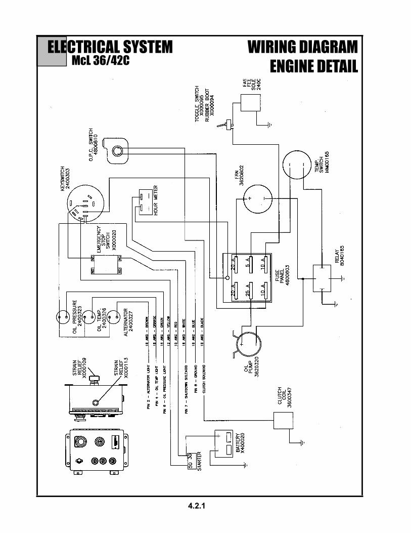
ELECTRICAL SYSTEMMcL 36/42C
WIRING DIAGRAM
ENGINE DETAIL
4.2.1

5.1 ENGINE DETAILS
DETAIL PAGE
ENGINE DESCRIPTION 5.1.1
MODEL DESIGNATION 5.1.2-5.1.3
ENGINE PARTS 5.1.4-5.1.7
OIL CIRCUIT & FUEL SYSTEM 5.1.8
COMMISSIONING 5.1.9-5.1.10
STARTING 5.1.11
MONITORING SYSTEMS 5.1.12
STOPPING 5.1.13
OPERATING CONDITIONS 5.1.14
LUBE OIL 5.1.15
FUEL 5.1.16
MAINTENANCE SCHEDULE 5.1.17
MAINTENANCE CHART 5.1.18
MAINTENANCE WORK COMPLETED 5.1.19-5.1.20
LUBRICATION SYSTEM 5.1.21-5.1.22
FUEL SYSTEM 5.1.23
COOLING SYSTEM 5.1.24
CUMBUSTION AIR FILTER 5.1.25-5.1.26
BELT DRIVES 5.1.27-5.1.28
ADJUSTMENTS 5.1.29
ACCESSORIES/BATTERY 5.1.30-5.1.31
ENGINE CLEANING 5.1.32
DIAGNOSIS CHART 5.1.33
ENGINE PRESERVATION 5.1.34
ENGINE SPECIFICATIONS
AND SETTINGS 5.1.35-5.1.36
TORQUE WRENCH SETTINGS/TOOLS 5.1.37
ORDERING SPARE PARTS 5.1.38
McL 36/42C
5.1.0

ENGINE DESCRIPTIONGENERAL 1
DEUTZ Diesel Engines
are the product of many years ofresearch and development.Theresulting know-how, coupledwith stringent quality standards,guarantee their long service life,high reliability and low fuelconsumption.It goes without saying thatDEUTZ Diesel Eninges meetthe hightest standeards forenviromental protection.
Beware of Running Engine
Shut the engine down beforecarrying out maintenance orrepair work. Ensure that theengine cannot be accidentallystarted. Risk of accidents.When the work is complete, besure to refit any panels andguards that have been removed.Never fill the fuel tanks while theengine is running. Observeindustrial safety regulationswhen running the engine in anenclosed space or under-ground.
Care and Maintenance
Sound care and maintenancepractices will ensure that theengine continues to meet therequirements placed on it.Recommended service intervalsmust be observed and serviceand maintenance work carriedout conscientiously.Special care should be takenunder abnormally demandingoperating conditions.
Safety
This symbol is used for
all safety warnings.
Please follow them carefully. The
attention of operating personnel
should be drawn to these safety
instructions. General safety and
accident prevention regulations
laid down by law must also be
observed.
Service
Please contanct one of our autho-rized service representatives in theevent of breakdowns or for spareparts inquiries. Our trained special-ists will carry out repairs quickly andprofessionally, using only genuinespare parts.Original parts from DEUTZ AG arealways produced in accordance withstate-of-the-art technology. Pleaseturn to the end of this manual forfurther intructions.
Asbestos
DEUTZ original parts are
asbestos-free.
5.1.1
CaliforniaProposition 65 Warning
Diesel engine exhaust and
some of its constituents are
known to the State of California
to cause cancer, birth defects,
and other reproductive harm

MODEL DESIGNATION2.1 Model
2.1.1 Rating Plate
The model A, the engine serial number B and the perfor-
mance data are stamped on the rating plate. The model and
engine serial number must be given when ordering parts.
2.1.2 Location of Rating Plate
The rating plate C is attached to the valve cover.
2.1.3 Engine Serial Number
The engine serial number B is stamped on the crankcase D as
well as the rating plate.
5.1.2

ENGINE DESCRIPTION2.1 Model
2.1.5 Fuel Delivery Lock
The manufacturer shall not be held liable for damages resulting
from adjustments made to the regulator by the operator. The
lock screws are protected in order to prevent this:
1. with locking paint on model:
torque balancer
2. with plastic protective cap on model:
without torque balancer
5.1.3
2.1.4 Numbering of Cylinders
Cylinders are numbered consecutively, beginning at the
flywheel end.
Adjustments to the regulator are to be carried out only by
authorized DEUTZ SERVICE - specialists.

ENGINE DESCRIPTION2.2 Engine Illustrations
2.2.1 Service Side FL 1011F
2.2.2 Exhaust Side FL 1011F
5.1.4
1 Oil filler neck (valve-gear cover)
2 Charge-air line / air-intake line
3 Fan with integrated generator
4 Narrow V-belt
5 Solenoid
6 Toothed belt cover
7 V-belt pulley on crankshaft
8 Oil Sump
9 Cut-out handle
10 Speed control lever
11 Oil dipstick
12 Crankshaft housing
13 Oil fill point ( on side of crankcase )
14 Fuel pump
15 Easy-change fuel filter
16 Connecting facitlity for oil heater
17 Lube oil easy-change filter
18 Removable coolant intake hood
19 Injection pumps
20 Date plate
21 Oil cooler
22 Date plate
23 Connection housing (SAE)
24 Flywheel with ring gear
25 Starter
26 Front cover
27 Crankcase
28 Cylinder head
29 Exhaust manifold pipe
30 Air-intake pipe

ENGINE DESCRIPTION2.2 Engine Illustrations
22 Cylinder head
23 Exhaust manifold pipe
24 Flywheel with ring gear
25 Starter
26 Crankshaft housing
27 Inlet line to TC (Lube oil)
28 Return line from TC (Lube oil)
29 Induction pipe
30 Turbocharger (TC)
31 Intake manifold
32 Air-intake line
2.2.4 Exhaust Side BFL 1011F
2.2.3 Service Side BFL 1011F
5.1.5
1 Oil filler neck (valve-gear housing cover)
2 Charge-air line / air-intake line
3 Fan with integrated generator
4 Narrow V-belt
5 Solenoid
6 Wheel-house cover
7 V-belt pulley on crankshaft
8 Oil sump
9 Cut-out handle
10 Speed control lever
11 Oil dipstick
12 Crankshaft housing
13 Oil fill point (on side of crankcase)
14 Fuel pump
15 Easy-change fuel filter
16 Connection facility for oil heater
17 Charge-air pressure full-load stop (LDA)
18 Lube oil easy-change filter
19 Removable coolant intake hood
20 Injection pumps
21 Oil cooler

ENGINE DESCRIPTION2.2 Engine Illustrations
2.2.5 Service Side FM 1011F
2.2.6 Exhaust Side FM 1011F
1 Oil filler neck (valve-gear housing)
2 Charge-air line / air-intake line
3 Generator
4 Narrow V-belt
5 Solenoid
6 Wheel-house cover
7 V-belt pulley on crankshaft
8 Oil sump
9 Cut-out handle
10 Speed control lever
11 Oil dipstick
12 Crankshaft
13 Oil fill point (on side of crankcase)
14 Fuel pump
15 Easy-change fuel filter
16 Connecting facility for oil heater
17 Lube oil easy-change filter
18 Injection pumps
19 Connection for oil cooler
20 Leakage-fuel line
21 Injection vavles
5.1.6
22 Cylinder head
23 Exhaust manifold line
24 Flywheel with ring gear
25 Starter
26 Front cover
27 Crankcase
28 Intake pipe
2.2.8 Exhaust side BFM 1011F
ENGINE DESCRIPTION2.2 Engine Illustrations
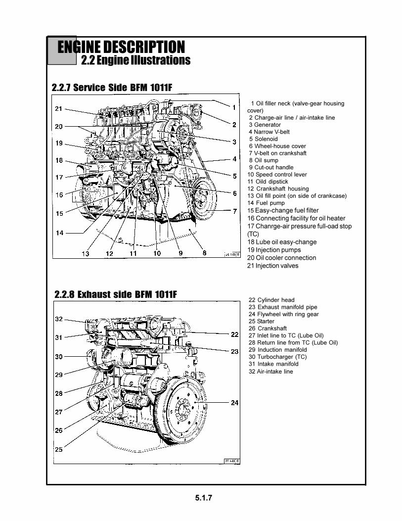
2.2.7 Service Side BFM 1011F
5.1.7
1 Oil filler neck (valve-gear housing
cover)
2 Charge-air line / air-intake line
3 Generator
4 Narrow V-belt
5 Solenoid
6 Wheel-house cover
7 V-belt on crankshaft
8 Oil sump
9 Cut-out handle
10 Speed control lever
11 Oild dipstick
12 Crankshaft housing
13 Oil fill point (on side of crankcase)
14 Fuel pump
15 Easy-change fuel filter
16 Connecting facility for oil heater
17 Chanrge-air pressure full-oad stop
(TC)
18 Lube oil easy-change
19 Injection pumps
20 Oil cooler connection
21 Injection valves
22 Cylinder head
23 Exhaust manifold pipe
24 Flywheel with ring gear
25 Starter
26 Crankshaft
27 Inlet line to TC (Lube Oil)
28 Return line from TC (Lube Oil)
29 Induction manifold
30 Turbocharger (TC)
31 Intake manifold
32 Air-intake line

2.3 Oil Circuit & 2.4 Fuel System
1 Oil sump
2 Intake manifold
3 Oil pump
4 Main oil duct
5 Oil-cooled cylinder
6 Cylinder head cooling neck
7 Oil duct for rocker arm lubrication
8 Rocker arm
9 Oil manifold for the thermostat
10 Intake to external engine oil cooler
11 Return from external engine oil
cooler
12 Thermostat housing with slide
thermostat
13 Oil duct to oil filter
14 Oil filter
15 Oil duct to the cam, con-rod and
crankshaft bearing
16 Injection jet for cooling the pistons
17 Oil return via crankcase to the oil
sump
18 Lube oil intake to turbocharger
19 Turbocharger
20 Return from turbochanger to oil
sump
ENGINE OPERATION
5.1.8
2.3.1 Lube Oil Circuit Schematic
2.4.1 Fuel system schematic 1 Fuel line from tank to fuel pump
2 Fuel pump
3 Fuel line from pump to easy-change fuel
filter
4 Easy-change fuel filter
5 Fuel line from filter to injection pump
6 Injection pumps
7 Fuel distributor line
8 Injection lines
9 Injection valves
10 Fuel leakage line
11 Fuel overflow pipe
12 Fuel return to tank
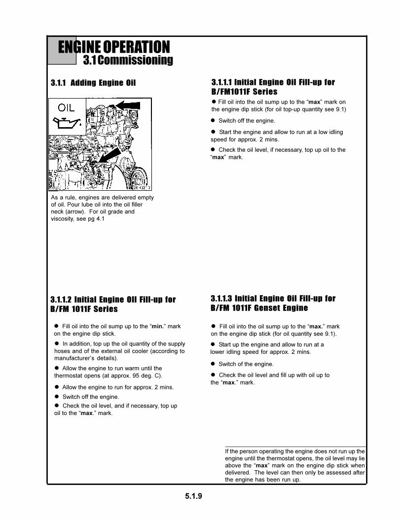
ENGINE OPERATION3.1 Commissioning
As a rule, engines are delivered empty
of oil. Pour lube oil into the oil filler
neck (arrow). For oil grade and
viscosity, see pg 4.1
l Fill oil into the oil sump up to the “min.” mark
on the engine dip stick.
l In addition, top up the oil quantity of the supply
hoses and of the external oil cooler (according to
manufacturer’s details).
l Allow the engine to run warm until the
thermostat opens (at approx. 95 deg. C).
l Allow the engine to run for approx. 2 mins.
l Switch off the engine.
l Fill oil into the oil sump up to the “max.” mark
on the engine dip stick (for oil quantity see 9.1).
3.1.1 Adding Engine Oil 3.1.1.1 Initial Engine Oil Fill-up for
B/FM1011F Series
3.1.1.2 Initial Engine OIl Fill-up for
B/FM 1011F Series
3.1.1.3 Initial Engine Oil Fill-up for
B/FM 1011F Genset Engine
5.1.9
l Fill oil into the oil sump up to the “max” mark on
the engine dip stick (for oil top-up quantity see 9.1)
l Start the engine and allow to run at a low idling
speed for approx. 2 mins.
l Switch off the engine.
l Check the oil level, if necessary, top up oil to the
“max” mark.
l Check the oil level, and if necessary, top up
oil to the “max.” mark.
l Start up the engine and allow to run at a
lower idling speed for approx. 2 mins.
l Switch of the engine.
l Check the oil level and fill up with oil up to
the “max.” mark.
If the person operating the engine does not run up the
engine until the thermostat opens, the oil level may lie
above the “max” mark on the engine dip stick when
delivered. The level can then only be assessed after
the engine has been run up.
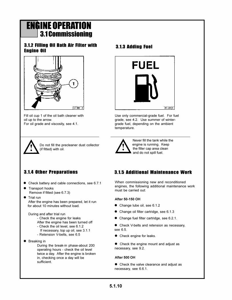
ENGINE OPERATION3.1 Commissioning
3.1.2 Filling Oil Bath Air Filter with
Engine Oil
Fill oil cup 1 of the oil bath cleaner with
oil up to the arrow.
For oil grade and viscosity, see 4.1.
3.1.3 Adding Fuel
l Transport hooks
Remove if fitted (see 6.7.3)
l Breaking in
During the break-in phase-about 200
operating hours - check the oil level
twice a day. After the engine is broken
in, checking once a day will be
sufficient.
l Check battery and cable connections, see 6.7.1
l Change fuel filter cartridge, see 6.2.1.
l Change lube oil, see 6.1.2
When commissioning new and reconditioned
engines, the following additional maintenance work
must be carried out:
3.1.4 Other Preparations
Never fill the tank while the
engine is running. Keep
the filler cap area clean
and do not spill fuel.
5.1.10
Use only commercial-grade fuel. For fuel
grade, see 4.2. Use summer of winter-
grade fuel, depending on the ambient
temperature.
Do not fill the precleaner dust collector
(if fitted) with oil.
l Trial run
After the engine has been prepared, let it run
for about 10 minutes without load.
During and after trial run
- Check the engine for leaks
After the engine has been turned off
- Check the oil level, see 6.1.2
If necessary, top up oil, see 3.1.1
- Retension V-belts, see 6.5
l Check V-belts and retension as necessary,
see 6.5.
3.1.5 Additional Maintenance Work
l Check engine for leaks.
l Change oil filter cartridge, see 6.1.3
After 50-150 OH
l Check the engine mount and adjust as
necessary, see 9.2.
After 500 OH
l Check the valve clearance and adjust as
necessary, see 6.6.1.

ENGINE OPERATION3.2 Starting
3.2.1 Electric Starting
with Cold-Start Aid
- Glow Plug
with Cold-Start Aid
- Ether Starting System
l Where possible, disengage the
clutch to separate the engine
from any driven parts.
Before starting, make
sure that nobody is
standing in the immediate
vicinity of the engine or
driven machine.
After repair work:
Check that all guards have been
replaced and that all tools have been
removed from the engine.
When starting with flame glow system,
do not use any other starter substance
(e.g. injection with start pilot).
Caution: If the speed regulator hasbeen removed, the engine must notbe tested under any circumstances:Disconnect the battery.
Starting without Cold-Start Aid
l Move speed control lever 1
into idle position.
l Insert key.
- Position 0 = no operating voltage
l Turn key clockwise
- Position 1 = no operating
voltage
- Pilot lights come on.l Push the key in and turn it further
clockwise against spring pressure
- Position 2 = no function
- Position 3 = start
l Insert key.
- Position 0 = no operating voltage
l Turn key clockwise.
- Position 1 = operating voltage
- Pilot lights come on.
l Push the key in and turn further
clockwise against spring pressure
- Glow plug indicator light comes on
- Position 2 = Preheat, hold for approx
1 minute.
- Preheat lamp comes on.
- Position 3 = Start
l Release key as soon as engine fires.
- Pilot lights go out.
l Insert key.
- Position 0 = no operating voltage
l Turn key clockwise
- Position 1 = operating voltage
- Pilot lights comes on.
l Starting fluid is injected automati-
cally in switch position A, as long
as the starter is operated.
l To assist acceleration at lower
temperatures and to avoid white
fumes, briefly hold the arctic
switch in switch position H.l Push key in and turn further clockwise
against spring pressure
- Position 2 = no function
- Position 3 = start
l Release key as soon engine fires
- Pilot lights go out
Do not actuate the starter for more than 20seconds. If the engine does not catch wait aminute then try again.If the engine does not catch after two attempts,refer to the Diagnosis Chart (see 7.1)
5.1.11
l Move cut-out handle, 2, into
operating position.
The switch must not be
moved to position H when
the engine is switched off
and the ignition is switched on.

ENGINE OPERATION3.3 Monitoring Systems
3.3.1 Engine Oil Pressure
Oil Pressure Pilot Light
l The oil pressure pilot light comes
on with operating voltage on and
engine off.
l The engine temperature gauge
pointer should remain in the green
sector most of the time. It should
rarely enter the yellow-green
sector. If the pointer enters the
orange sector, the engine is
overheating. Turn off and
establish the cause from the
Diagnosis Chart (see 7.1).
l The oil pressure pilot light should
go out when the engine is running.
l The pointer must remain in the
green sector over the entire range.
Oil Pressure Indicator Oil Pressure Gauge
l The pointer must indicate
the minimum oil pressure (see 9.1).
Temperature Gauge
3.3.2 Engine Tempera-
5.1.12
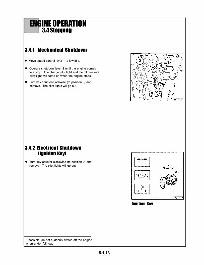
3.4 Stopping
l Move speed control lever 1 to low idle.
3.4.1 Mechanical Shutdown
3.4.2 Electrical Shutdown
(Ignition Key)
l Operate shutdown lever 2 until the engine comes
to a stop. The charge pilot light and the oil pressure
pilot light will come on when the engine stops.
l Turn key counter-clockwise (to position 0) and
remove. The pilot lights will go out.
l Turn key counter-clockwise (to position 0) and
remove. The pilot lights will go out.
Ignition Key
5.1.13
ENGINE OPERATION
If possible, do not suddenly switch off the engine
when under full load.
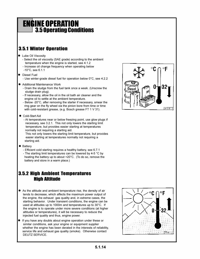
ENGINE OPERATION3.5 Operating Conditions
3.5.1 Winter Operation
3.5.2 High Ambient Temperatures
High Altitude
l Lube Oil Viscosity
- Select the oil viscosity (SAE grade) according to the ambient
temperature when the engine is started, see 4.1.2
- Increase oil change frequency when operating below
-10°C, see 6.1.1
l Diesel Fuel
- Use winter-grade diesel fuel for operation below 0°C, see 4.2.2
l Additional Maintenance Work
- Drain the sludge from the fuel tank once a week. (Unscrew the
sludge drain plug).
- If necessary, allow the oil in the oil bath air cleaner and the
engine oil to settle at the ambient temperature.
- Below -20°C, after removing the starter if necessary, smear the
ring gear on the fly wheel via the pinion bore from time or time
with cold-resistant grease, (e.g. Bosch grease FT 1 V 31).
l Cold-Start Aid
- At temperatures near or below freezing point, use glow plugs if
necessary, see 3.2.1. This not only lowers the starting limit
temperature, but provides easier starting at temperatures
normally not requiring a starting aid.
This not only lowers the starting limit temperature, but provides
easier starting at temperatures normally not requiring a
starting aid.
l Battery
- Efficient cold starting requires a healthy battery, see 6.7.1
- The starting limit temperatures can be lowered by 4-5 °C by
heating the battery up to about +20°C. (To do so, remove the
battery and store in a warm place.)
l As the altitude and ambient temperature rise, the density of air
tends to decrease, which affects the maximum power output of
the engine, the exhaust gas quality and, in extreme cases, the
starting behavior. Under transient conditions, the engine can be
used at altitudes up to 1000m and temperatures up to 30°C. If
the engine is to operate under more severe conditions (at higher
altitudes or temperatures), it will be necessary to reduce the
injected fuel quality and thus, engine power.
l If you have any doubts about engine operation under these or
similar conditions, ask your engine or equipment supplier
whether the engine has been derated in the interests of reliability,
service life and exhaust gas quality (smoke). Otherwise contact
DEUTZ SERVICE.
5.1.14

OPERATING MEDIA4.1 Lube Oil
4.1.1 Quality Grade
4.1.2 Viscosity
Lube oils are differentiated by Deutz according to
their performance and quality class. Oils of other,
comparable specifications can be used.
Generally, multi-grade oils shall be used. In closed
heated rooms at temperatures >5 deg.C, also
single-grade oils can be used.
As the viscosity of lube oil is dependent on tempera-
ture, the choice of SAE grade should be governed by
the ambient temperature prevailing at the engine
operating site.
Optimum operating behaviour will be attained if you
take the accompanying oil viscosity diagram as a
guide.
Should the temperature fall temporarily below the
limits of the SAE grade selected, cold starting may
be affected but the engine will not be damaged.
In order to keep wear to a minimum, do not exceed
application limits for extended perious of time.
Synthetic lube oils feature an improved temperature
and oxidation stability.
5.1.15
The precise assignment of the admissable oil
qualities to the engines is indicated in chapter 6.1.1.
If in doubt, contact you service representa

OPERATING MEDIA4.2 Fuel
l Diesel fuel- DIN EN 590
- BS 2869: A1 and A2
(with A2, take note of the sulpher content)
- ASTM D 975-88; 1-D and 2-D
- NATO Code F-54 and F-75
- ISO 8217 DMS
- ISO 8217 DMA
Use commercially available diesel fuel with less
than 0.5% sulphur content. If the sulphur content is
higher than 0.5% oil change intervals should be
reduced, see 6.1.1
The following fuel specifications / standards are
approved:
(refer to TR 0199-3002)
4.2.1 Quality Grade
4.2.2 Winter-Grade Fuel
Exhaust emission levels which may be determined
in the cause of type approval tests always refer to
the reference fuel prescribed by the authorities for
the type approval test.
Waxing may occur at low temperatures, clogging the
fuel system and reducing engine efficiency. If the
ambient temperature is less than 0°C, winter-grade
fuel (suitable down to -20°C) should be used. This
fuel is usually available from the filling stations well
in advance of the cold months.
If summer-grade diesel fuel must be used at
temperatures below 0°C, up to 60% kerosene can
be added (see diagram).
In most cases, adequate resistance to cold can be
obtained by adding a flow improver (additive).
Please contact your DEUTZ partner.
l At temperatures below -20°C, kerosene should
be added to the diesel fuel. The relevent percent-
ages are given in the diagram at the right.
l Special diesel fuels can be used for climatic
zones down to -44°C.
Mix in tank only. Fill with the
appropriate amount of kerosene
first, then add the diesel fuel.
5.1.16
l Light heating oilaccording to DIN 51603
ASTM D 396; 1 and 2
BS 2869 Class D
l Jet Fuel- F34/F35/F44 (kerosene)
- F54 (equivalent to diesel fuel
according to DIN EN 590)
- XF 63 (equivalent to F34 + F35 with
l Bio diesel fuel- according to DIN 51606 - FAME
Diesel fuels must never be mixed
with petrol (norrmal and super grade
petrol)!

ROUTINE MAINTENANCE5.1 Maintenance Schedule
5.1.17
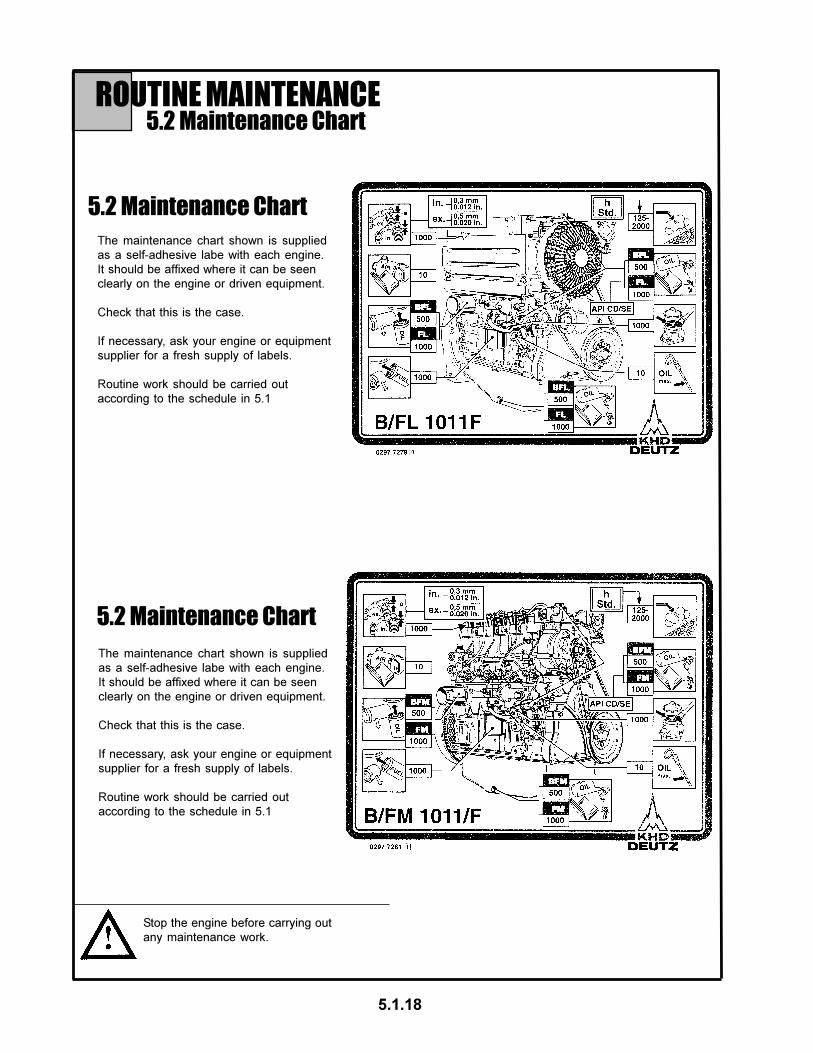
ROUTINE MAINTENANCE5.2 Maintenance Chart
5.2 Maintenance Chart
The maintenance chart shown is supplied
as a self-adhesive labe with each engine.
It should be affixed where it can be seen
clearly on the engine or driven equipment.
Check that this is the case.
If necessary, ask your engine or equipment
supplier for a fresh supply of labels.
Routine work should be carried out
according to the schedule in 5.1
Stop the engine before carrying out
any maintenance work.
5.1.18
The maintenance chart shown is supplied
as a self-adhesive labe with each engine.
It should be affixed where it can be seen
clearly on the engine or driven equipment.
Check that this is the case.
If necessary, ask your engine or equipment
supplier for a fresh supply of labels.
Routine work should be carried out
according to the schedule in 5.1
5.2 Maintenance Chart

ROUTINE MAINTENANCE5.3 Maintenance Work Completed
5.1.19

ROUTINE MAINTENANCE5.3 Maintenance Work Completed
5.1.20

SERVICE AND MAINTENANCE6.1 Lubrication System
6.1.1 Oil Change Intervalsl The oil change intervals are
dependent on the engine application
and the quality of the lube oil.
l If the engine runs fewer hours during
the year than stated in the table, the
oil should be changed at least once
a year.l The table refers to the following
conditions:
- For diesel fuel: sulphur content max.
0.5% by weight.
- Continuous ambient temperatures
down to -10°C (+14°F)
l If the sulphur content is > 0.5 to 1% or
the continuous ambient temperature
below -10°C (+14°F), the intervals
between oil changes should be
halved.
l In case of fuels containing more than
1% sulphur, contact your service representative.
6.1.2 Checking Oil/
Checking Engine Oil
6.1.2.1 Checking Oil Level 6.1.2.2 Engine Oil Change
Gensets as referred to here are units operating in
parallel with the main / with each other. Emergency
power units are dealt with in TC 0199-99-1126.
l Check the oil level with the engine
turned off.l Allow the engine to warm up.
l Check the oil level, and if necessary,
top up to the “MAX” mark. If the oil
level is only just above the “MIN” mark, more oil must be added.
l Wipe the dipstick with a non-fibrous,
clean cloth.
l Remove the oil dipstick
l Ensure that the engine or vehicle is in
a level postition.
l Insert it to the top and remove again.
The oil level must not fall below the “MIN”
marking.
l Ensure that the engine or vehicle is
on a level postition.
l Turn the engine off.
l Place oil tray under the engine.
l Unscrew drain plug.
l Fit oil drain plug, with the
new gasket and tighten firmly
(for torque, see 9.2)
l Pour in lube oil.
- For grade/viscosity, see 4.1
- For quantity, see 9.1
l Drain oil.
l Check oil level, see 6.1.2.1
Be careful when draining hot oil -
danger of scalds! Do not let used
oil run into the soil but catch it in
a container ready for proper
disposal.
5.1.21

SERVICE AND MAINTENANCE6.1 Lubrication System
6.1.3 Changing Oil Filter
6.2.1 Changing Fuel Filter
l Undo the filter cartridge using a
commercial tool and spin off.
l Catch any dripping oil.
l Clean any dirt from the filter
carrier rim.
l Screw in the new cartridge finger
tight against the gasket.
l Lightly oil the rubber gasket of the
new oil filter cartridge.
l Apply light film of oil or diesel fuel
to the rubber gasket of the new fuel
filter cartridge.
l Tighten the fuel filter cartridge
with a final half-turn.
l Close fuel stopcock.
l Undo fuel filter cartridge with com-
mercial tool and spin off.
l Clean any dirt from the filter cartridge
with a final half-turn.
l Catch any fuel.l Check for leaks.
l Open fuel stopcock.
Beware of burns from hot oil.
5.1.22
l Screw in the new cartridge finger
tight against the gasket.
Keep naked flames away when
working on the fuel system. Do
not smoke!The fuel system does not need to
be bled.

SERVICE AND MAINTENANCE6.2 Fuel System
6.2.2 Fuel Pump
Cleaning the Strainer
l Close the fuel shut-off valve.
l Remove the fuel stainer cover, 2,
(cover and strainer one unit).
l Loosen and unscrew the
hexagonal nut 1.
No naked flames when working
on the fuel system.
NO SMOKING!
5.1.23
l Clean the fuel stainer with
diesel fuel. Replace if necessary.
l Place seals, 3, in position.
l Mount the fuel strainer cover,2.
l Tighten the hexagonal screw, 1.
6.2.3 Change Fuel Leakage LIne
l Close the fuel shutoff valve
l Disconnect rubber hose, 1, from fuel
tank.
l Disconnect rubber hoses, 4, 3 and 1
from unions, 2, and dispose of in an
environmentally friendly manner.
l Disconnect rubber hoses, 3, from the
injection valves.
l Connect new rubber hoses 4, 3, and 1, to
unions, 2.
l Connect rubber hoses 3 to injection
valves.
l Open fuel shutoff valve
l Check for leaks after start-up.
l Check for leaks.

SERVICE AND MAINTENANCE6.3 Cooling System
6.3.1 Cleaning Intervalsl The amount of contamination in the
cooling system depends on the
engine application.
l Spilled oil or fuel on the engine
increases the risk of contamination.
Be especially careful if the engine
is used in dusty environments.
l Because applications vary, cleaning
intervals have to be determined from
case to case. The cleaning intervals
given in the table on the below can be
used as a guide.
l Serious contamination can occur,
for example:
- on construction sites where there is
a high level or air borne dust.
- in harvesting applications where
here are high concentrations of chaff
and chopped straw in the vicinity of
the machine.
5.1.24
l Clean the engine as described in 6.8.1.

l The amount of dirt in the air cleaner depends on the
amount of dust in the air and the size of the air
cleaner used. If a high level of dust is anticipated, a
cyclone-type precleaner can be fitted to the air
cleaner.
l Cleaning intervals will have to be determined from
case to case.
l After carrying out service work, reset the signal by
pressing the button on the service indicator.
l Air cleaner servicing is needed when:
- Service indicator the red signal, 1, is fully visible when the engine
is off.
- Service switch the yellow pilot light comes on when the engine
is running.
SERVICE AND MAINTENANCE6.4 Combustion Air Filter
l Release snap clips 2 and remove oil
cup 3 together with filter element 4. If
necessary pry element out with a
screwdriver, taking care not to damage
the rubber gasket 5.
l Remove dirty oil and sludge. Clean
oil cup.
l Clean filter element 4 in diesel fuel
and allow to drip-dry.
l Inspect and replace rubber
gasket 5 and 6 if necessary.
l Clean filter housing 1 if very
dirty.
l Undo wing nut 1 and remove cover 2.
l Reposition collector bowl 3 onto
lower section 4, fasten cover 2 in
place by tightening wing nut 1.
l Turn engine off and wait about 10
minutes for the oil to drain from filter
housing 1.l Remove collector bowl 3 from lower
section 4 and empty. Clean leaves,
straw and other foreign matter from
lower section of precleaner.
l Refit oil cup and element to
filter housing and secure with
snap rings.
l Fill oil cup with engine oil up
to the mark (arrow)
(for viscosity, see 4.1.2).
6.4.1 Cleaning Intervals
6.4.2 Emptying Cyclone
Type Precleaner6.4.3 Cleaning Oil Bath Air Cleaner
Never clean air cleaner withgasoline. Dispose of cold oil inaccordance with environmentalregulations.
Never fill collector bowl with oil. Replace
collector bowl if damaged.
5.1.25

SERVICE AND MAINTENANCE6.4 Combustion Air Filter
l Undo clip fasteners 1.
l Take off hood 2 and remove cartridge 3.
l Clean cartridge 3.
Blow out from inside out with dry
compressed air (max. 5 bar), (or in difficult
cases, tap out, taking care not to damage
the cartridge, or wash according to
manufacturer’s instructions.
l The amount of dirt in the air cleaner
depends on the amount of dust in the
air and the size of the air cleaner used.
If a high level of dust is anticipated, a
cyclone-type precleaner can be fitted
to the air cleaner.
l Cleaning intervals will have to be
determined from case to case.
l Through regular removal and replacement,
the gaskets on the filter cartridge can
become damaged. Check paper filter (light
showing through) and gaskets for damage.
Replace if necessary.
l After five cleaner services or after two years
at the latest, replace safety cartridge 4
(never clean).
To do so:
- Undo hex. nut 5 and remove cartridge 4.
- Install new cartridge, insert and tighten
hex. nut.
l Install cartridge 3, replace hood 2 and
do up clip fasteners 1.
l Empty dust discharge valve 1 by pressing
apart lips of discharge slot as indicated by
arrows.
l Clean discharge slot from time to
l Remove any caked dirt by pressing together
the upper section of the valve.
6.4.4 Dry Type Air Cleaner
Dust Discharge Valve Filter Cartridges
l Clean cartridge (replace at least once a
year).
Never clean filter cartridge with
gasoline or hot fluids.
5.1.26
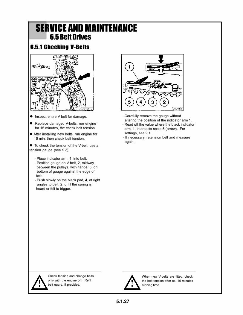
SERVICE AND MAINTENANCE6.5 Belt Drives
6.5.1 Checking V-Belts
5.1.27
l Inspect entire V-belt for damage.
l Replace damaged V-belts, run engine
for 15 minutes, the check belt tension.
l After installing new belts, run engine for
15 min. then check belt tension.
l To check the tension of the V-belt, use a
tension gauge (see 9.3).
- Place indicator arm, 1, into belt.
- Position gauge on V-belt, 2, midway
between the pulleys, with flange, 3, on
bottom of gauge against the edge of
belt.
- Push slowly on the black pad, 4, at right
angles to belt, 2, until the spring is
heard or felt to trigger.
- Carefully remove the gauge without
altering the position of the indicator arm 1.
- Read off the value where the black indicator
arm, 1, intersects scale 5 (arrow). For
settings, see 9.1.
- If necessary, retension belt and measure
again.
Check tension and change belts
only with the engine off. Refit
belt guard, if provided.
When new V-belts are fitted, check
the belt tension after ca. 15 minutes
running time.

l Retighten bolts 1,2 and 3.
SERVICE AND MAINTENANCE6.5 Belt Drives
6.5.2 Tensioning Alternator Belts
l Slacken off bolts 1,2 and 3.
l Adjust alternator, 4, in direction of arrow
by turning bolt 3 until correct belt tension
is achieved.
5.1.28
6.5.3 Changing Alternator Belts
l Slacken off bolts 1,2 and 3.
l Adjust alternator, 4, in direction of arrow
by turning bolt 3.
l Remove and replace belt.
l Adjust alternator, 4, against the direction
of the arrow by turning bolt 3, until correct
belt tension is achieved.
l Retighten bolts 1, 2 and 3.
Check tension and change belts
only with the engine off. Refit
belt guard, if provided.

l Adjust valve clearance if necessary:
- Release locknut 4.
- Use screwdriver 7 to turn setscrew 5 so
that the correct clearance is attained after
locknut 4 has been tightened.
l Check valve clearance 1 between rocker
arm / tappet contact face 2 and valve stem
3 with feeler gauge 6 (there should be only
slight resistance when feeler blade is
inserted).
For permissible valve clearance, see 9.1
l Remove the cylinder head cover.
l Before adjusting valve clearance, allow
engine to cool down for at least 30 minutes.
The oil temperature should be below 80°C.
l Position crankshaft as per schematic
6.6.1 Checking / Adjusting
Valve Clearances
6.6.1.1 Valve Clearance
Adjustments Sche-
l Check and adjust valve clearance on all
remaining cylinders.
SERVICE AND MAINTENANCE6.6 Adjustments
l Replace cylinder head cover (use new gasket
if needed).
l Crankshaft Position 1: Turn crankshaft until both valves in
cylinder 1 overlap (exhaust valve
about to close, inlet valve about to
open). Adjust clearance of valve
marked in black on schematic.
Mark respective rocker arm with
chalk to show that adjustment has
been done.
l Crankshaft Position 2: Turn crankshaft one full revolution
(360°). Adjust clearance of valves
marked in black on schematic.
5.1.29

l Keep battery clean and dry.
6.7.1 Battery
6.7.1.1 Checking Battery and
Cable Connectors
SERVICE AND MAINTENANCE6.7 Accessories
l Clean terminal posts (+ and - )
and clamps of the battery, grease
with acid-free and acid-resistant
grease.
l Undo dirty clamps.
l Remove caps 1.
l If testers are not used, the
electrolyte level should be 10 -
15mm above the top of the plates.
l If testers 2 are used, the electrolyte should come up to their base.
l When reassembling, ensure that clamps make good contact. Turn clamp bolts finger tight.
l If necessary, top up with distilled
water.
l Replace caps.
l Measure the electrolyte density of individual cells with a commercial hydrometer.
The hydrometer reading (see table on following page) indicates the state of charge. During measurement, the temperature of the electrolyte should preferably be +20°C.
The gasses emitted by the battery
are explosive! Keep sparks and
naked flames away from the
battery.
Do not allow battery acid to comeWear protective goggles. Do not rest tools on
the battery.
5.1.30
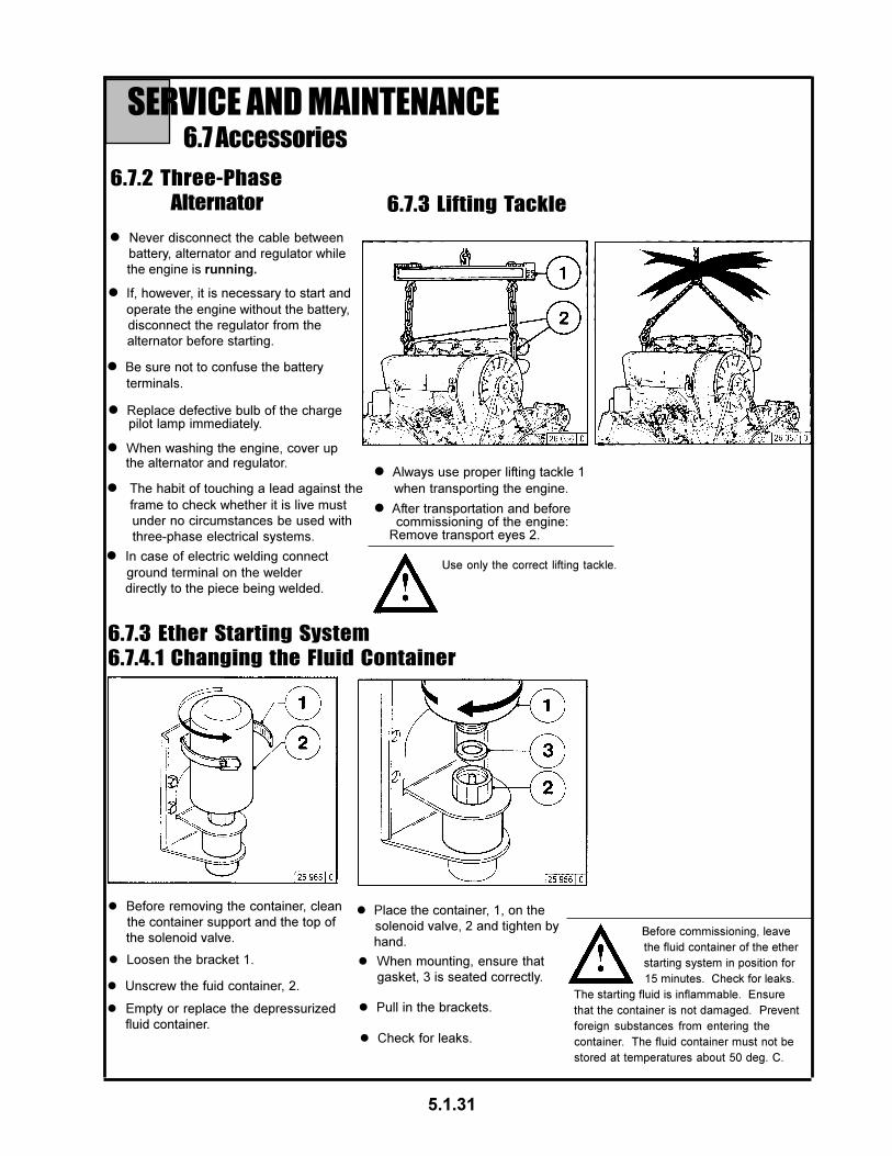
Before commissioning, leave
the fluid container of the ether
starting system in position for
15 minutes. Check for leaks.
The starting fluid is inflammable. Ensure
that the container is not damaged. Prevent
foreign substances from entering the
container. The fluid container must not be
stored at temperatures about 50 deg. C.
l Never disconnect the cable between
battery, alternator and regulator while
the engine is running.
l Be sure not to confuse the battery
terminals.
l If, however, it is necessary to start and
operate the engine without the battery,
disconnect the regulator from the
alternator before starting.
l After transportation and before commissioning of the engine: Remove transport eyes 2.
l In case of electric welding connect
ground terminal on the welder
directly to the piece being welded.
l Always use proper lifting tackle 1
when transporting the engine.
l Replace defective bulb of the charge pilot lamp immediately.
l The habit of touching a lead against the
frame to check whether it is live must
under no circumstances be used with
three-phase electrical systems.
l When washing the engine, cover up the alternator and regulator.
Use only the correct lifting tackle.
6.7.2 Three-Phase
Alternator
6.7 Accessories
SERVICE AND MAINTENANCE
6.7.3 Lifting Tackle
5.1.31
6.7.3 Ether Starting System
6.7.4.1 Changing the Fluid Container
l Before removing the container, clean
the container support and the top of
the solenoid valve.
l Loosen the bracket 1.
l Unscrew the fuid container, 2.
l Empty or replace the depressurized
fluid container.
l Place the container, 1, on the
solenoid valve, 2 and tighten by
hand.
l When mounting, ensure that
gasket, 3 is seated correctly.
l Pull in the brackets.
l Check for leaks.

6.8 Engine CleaningSERVICE AND MAINTENANCE
6.8.1 Engine Cleaning
l Switch off the engine.
l Remove engine covers, cooling-air hoods. Replace them after cleaning and before the test run.
l Clean the engine with a steam jet (max. spray pressure. of 60 bar, max. steam pressure of 90deg.C.
l Cover electrical / electronic components / connections (e.g. alternator, starter, govener, solenoid).
l Blow air through the engine, taking particular care not to damage the cooler and cooling fins (begin to blow through air from exhaust side.) Remove the dirt which has blown into the interior space.
l Allow the engine to run up so that the remaining water evaporates.
l Allow the engine to run up so that the remaining water evaporates.
5.1.32
Preparation
Using high pressure device
Using compressed air
l Spray the engine with the commercial cold- cleaning compound and allow to react for approximately 10 mins.
Using cold-cleaning compound
l Spray clean the engine with a strong water jet, repeat if necessary.
Clean engine only when the engine
is switched off.

7.1 Diagnosis ChartFAULTS, CAUSES AND REMEDIES
5.1.33
If the engine is to remain idle for an extended period of time, itis necessary to take protective measures to prevent rustformation. The preservative measures described here willprotect the engine for up to 6 months. The procedure will haveto be reversed before the engine is recommissioned.
l Recommended cleansing agent to remove preservatives
when recommissioning engine:
- Petroleum benzine (hazardous materials class A3)
l Anti-corrosion oils to specification: - MIL-L-21260B - TL 9150-037/2 - Nato Code C 640 / 642
l If necessary, clean oil bath cleaner, see 6.4.3, and fill with anti-corrosion oil.
l Run engine until warm, then turn off.
l Drain engine oil, see 6.1.2 and fill with anti-corrosion oil.
l Clean engine (with cold cleansing agent if preferred) using high pressure equipment.
l Make up a mixture of 90% diesel fuel and 10% anti-corrosion
oil, and refill fuel tank.
l Drain fuel from tank.
8.1.1 Preserving Engine
8.1ENGINE PRESERVATION
8.1.2 Removing Engine Preservatives
l Spray grooves on V-belts pulleys with anti-corrosion spray.
l Turn engine off.
l Turn engine over manually several times to preserve the cylinders and combustion chamber. When rotating with starter, place shut-off lever in stop position.
l Run engine for about 10 minutes.
l Remove plugs from intake port and exhaust port.
l Remove V-belts and store dry in wrapped condition.
l Install V-belts. Retension after brief operation if necessary, see 6.5
l Set the engine in operation.
l Remove anti-corrosion agent from grooves in V-belt pulleys.
5.1.34

9.1 Engine Specifications and SettingsTECHNICAL SPECIFICATIONS
5.1.35
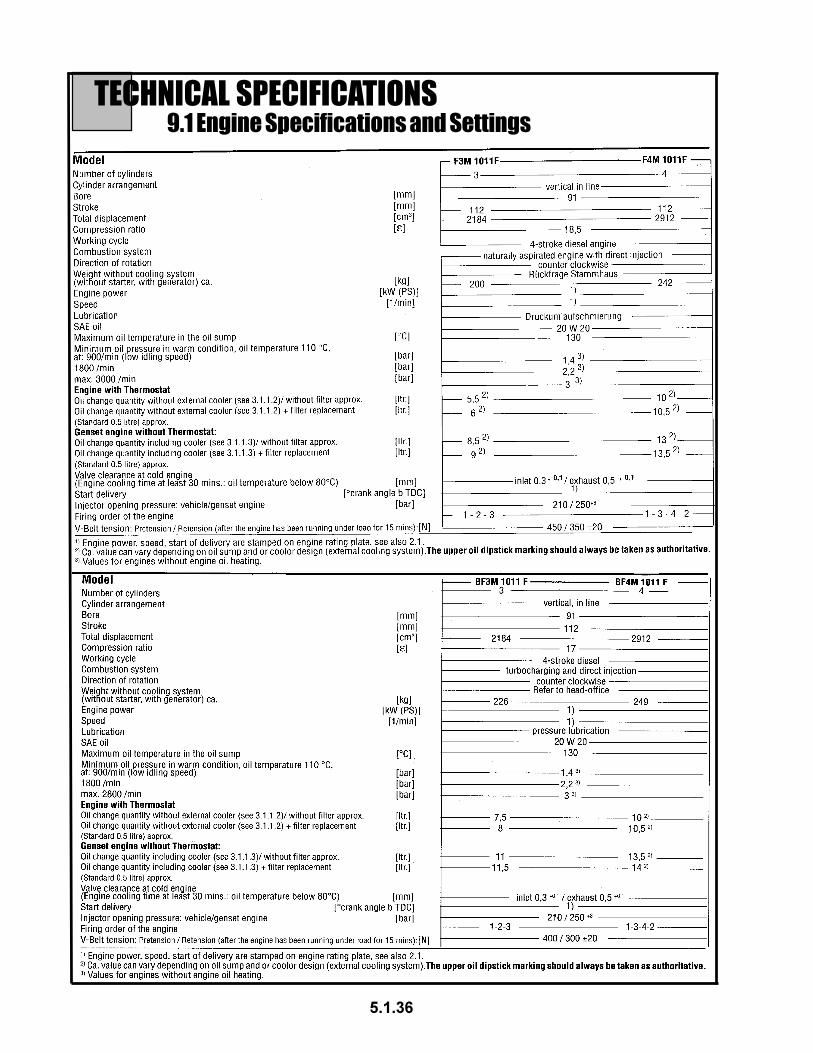
9.1 Engine Specifications and SettingsTECHNICAL SPECIFICATIONS
5.1.36

9.2 Torque Wrench SettingsTECHNICAL SPECIFICATIONS
9.3 Tools
The V-belt tension gauge can be obtainedunder order number 81 15 + 81 20 from:
COMPANY WILBÄRPostfach 14 05 80D-42826 Remscheid
TECHNICAL SPECIFICATIONS
5.1.37
The TORX wrench set (order number 8189) isused with engines in the 1011 series.This system was chosen because of the manyadvatages it offers:
*Outsanding accessibility to bolts.*High load transfer when loosening and tightening.*Almost impossible for socket to slide off or break.


Order information
Please specify the following informa-tion when ordering original DEUTZparts.
- Engine no.
- Ident. no.
- Quantity
Document structure
- The picture diagrams in this spare parts list are sorted according to engine assembly groups.
- Each section is preceded by an overview of the assembly groups.
- The ident. no. 08/23 us made up of the assembly group (e.g. 08) and item number (e.g. 23).
5.1.38
ORDERING SPARE PARTSMcL 36/42C

TRANSMISSION PARTS
5.2.1
McL 36/42C

McL 36/42C
5.2.2
TRANSMISSION PARTS
#METI .YTQ REBMUN NOITPIRCSED
1 1 890031P llabdnaHreveLlortnoC
2 1 100031P paCgnisuoHlortnoC
3 1 990031P rehsaWgnirpSreveLlortnoC
4 1 001031P gnirpSreveLlortnoC
5 1 101031P ylbmessAreveLlortnoC
6 1 200031P gulPrepaT
7 6 300031P "578.X61-8/3CH,wercS
8 6 400031P "8/3kcoL,rehsaW
9 1 500031P dn2dnats1,kroFtfihS
01 6 600031P gulPnoisnapxE
11 1 700031P gnisuoHlortnoC
21 1 201031P niPgnisuoHlortnoC
31 1 800031P teksaGgnisuoHlornoC
41 2 900031P gnirpSteppoP
a41 1 301031P tceriDdnadr3,gnirpSteppoP
51 3 010031P llaBleetS
61 1 110031P dn2dnawoL,liaRtfihS
71 1 210031P dn2dnats1dnEliaRtfihS
81 1 310031P tceriDdnadr3,liaRtfihS
91 1 410031P tceriDdnadr3,kroFtfihS
02 1 510031P esreveR,liaRtfihS
12 1 610031P esreveR,dnEliaRtfihS
22 1 710031P rehsaW"C"regnulPesreveR
32 1 810031P "578.X8/1rettoC,niP
42 1 910031P "521.1X8/3gnirpS,niP
52 1 020031P toviPmrAgnitfihS
62 1 120031P mrAgnitfihSesreveR
72 1 220031P gniR-O
82 1 320031P niPrepaT
92 1 420031P rehsaW"C"eohSgnitfihS
03 1 520031P esreveR,eohSgnitfihS
13 2 620031P regnulPkcolretnI
23 1 720031P niPkcolretnI
33 1 820031P regnulPesreveR
43 1 920031P gnirpSregnulPesreveR
53 1 030031P llaBleetS
63 1 130031P gnirpSteppoP
73 2 230031P gniRpanSreldIesreveR
83 2 330031P rehsaWtsurhTreldIesreveR
93 1 530031P raeGreldIesreveR
04 1 630031P recapSrelloRreldIesreveR
14 47 730031P relloRgniraeB
24 1 830031P eveelStfahSreldIesreveR
34 1 930031P "8/3kcoL,rehsaW
44 1 040031P etalPkcoLtfahsretnuoCdnareldI
54 1 140031P tfahSreldIesreveR
64 1 240031P raeR,rehsaWtsurhTtfahsretnuoC
74 1 340031P rehsaWtsurhTtfahsretnuoC
#METI .YTQ REBMUN NOITPIRCSED
84 1 440031P sraeGtfpahsretnuoC
94 88 540031P relloRgniraeB
05 6 640031P recapSgniraeBraeGtfahsretnuoC
15 1 740031P recapSgniraeBtfahsretnuoC
25 1 840031P tnorF,rehsaWtsurhTtfahsretnuoC
35 1 940031P tfahsretnuoC
45 1 050031P raeGdeepSdn2dnawoL
55 1 150031P gniRgniniateRetalPtfihS
65 1 250031P llaBleetS.aiD8/3
75 1 350031P etalPgnitfihS
85 3 450031P gnirpS
95 1 550031P buHhctulCdeepSdn2dnawoL
06 3 750031P raeGdeepSdn2tfahSniaM
16 2 850031P gniRgnikcolBrezinorhcnyS
26 1 950031P raeGdeepSdn2tfahSniaM
36 1 060031P raeGdeepSdn2rehsaWtsurhT
46 1 160031P esaCnoissimsnarT
56 1 260031P tfahSniaM
66 1 360031P raeGdeepSdr3tfahSniaM
76 1 460031P gniRgnikcolBdezinorhcnyS
86 1 560031P eveelShctulCtceriDdnadr3y'ssAredrO
96 3 660031P etalPgnitfihS
07 2 760031P gnirpSdeznorhcnyS
17 1 860031P buHhctulCtceriDdnadr3y'ssAredrO
27 1 070031P recapSpanSbuHhctulC
37 1 170031P recapSgniraeB
47 1 270031P tuNtfahSniaM
57 1 370031P laeSliO
67 1 470031P "578.1X61-8/3CH,wercS
77 1 570031P recapSraeGretemodeepS
87 4 670031P "00.1X61-8/3CH,wercS
97 1 770031P teksaGreniateRgniraeBtfahSniaM
08 1 870031P gniRpanSgniraeB
18 1 680031P gniraeBralunnA
28 1 080031P teksaGreniateRgniraeBtfahSniaM
38 1 180031P teksaGrevoCgninepOrewoP
48 1 280031P revoCgninepOrewoP
58 6 380031P 526.X61-8/3CH,wercS
68 1 770031P raeGevirDniaM
78 1 580031P elffaBliOraeGevirDniaM
88 1 970031P gniraeBralunnA
98 1 870031P gniRpanSgniraeB
09 1 790031P reniateRgniraeBraeGevirDniaM
19 1 080031P teksaGreniataeRgniraeBtfahSniaM
29 1 980031P reniateRgniraeBraeGevirDniaM
39 4 090031P "61/5kcoL,rehsaW
49 4 190031P "578.X81-61/5laeSliO,tloB
59 5 290031P "8/3kcoL,rehsaW
69 1 004000U "4/3X61-8/3CH,wercS
79 1 390031P "4/3gulPrelliF
89 1 390031P "4/3gulPniarD
99 1 590031P rehtaeB
*001 1 a/n hctiwSthgILpukcaB
**101 1 7110063 tooFtroppuS
001metihtiwdecalpeR* nwohStoN**

GEARBOX PARTSMcL 36/42C
5.3.1

GEARBOX PARTSMcL 36/42C
5.3.2
#METI REBMUN NOITPIRCSED
51 51-1030263 tsurhT,rehsaW
61 61-1030263 tsurhT,gniraeB
A1 A1-1030263 eldnipS
6 6-1030263 tupnI,revoC
C1 C1-1030263 puC-derepaT,gniraeB
D1 D1-1030263 enoC-derepaT,gniraeB
B1 B1-1030263 ecaF,laeS
E1 E1-1030263 tsurhT,rehsaW
81 81-1030263 rdhS,tloB
5 5-1030263 gniR-O
8 8-1030263 tsurhT,rehsaW
42 51-1030263 *aidnI*DI,etalP
F1 F1-1030263 txE-gniR,noitneteR
52 52-1030263 evirD,wercS
16 16-1030263 FTPN-ngaM,gulPepiP
32 32-1030263 kcoL,rehsaW
22 22-1030263 kcoL,rehsaW
draobdraC,gulP
G1 G1-1030263 gnisuoH
E3 E3-1030263 tenalP,tfahS
G3 G3-1030263 tsurhT,recapS
A3 A3-1030263 reirraC
C3 C3-1030263 puC-derepaT,gniraeB
D3 D3-1030263 enoC-derepaT,gniraeB
H3 H3-1030263 noisnoitxE-gniR,noitneteR
B3 B3-1030263 lloR,niP
31 31-1030263 nuS,raeG
11 11-1030263 tupnI,tfahS
91 91-1030263 gnilpuoC
F3 F3-1030263 teSretsulC,raeG
2 2-1030263 lanretnI,raeG
4 4-1030263 gniR,raeG
21 21-1030263 tupnI,recapS
02 02-1030263 lanretnI-gniR,noitneteR
01 01-1030263 lanretxE-gniR,noitneteR

REPAIR INSTRUCTIONSMcL 36/42C
WARNING:Moving parts. Keep all guards in place. Shut
down engine before service or maintenance.
Being caught in machinery may cause
serious injury.
WARNING:High pressure. Leaking hydraulic fluid
under pressure can penetrate and cause
serious injury. Check for leaks with card
board. Relieve pressure before working on
any system.
WARNING:Crushing weight can cause serious injury.
Place machine on solid surface to prevent
rollover or falling.
WARNING:Do not modify this machine. Use only
authorized McLaughlin repair parts. Failure
to comply can result in serious injury.
Service this equipment according with
maintenance instructions in this manual.
TRANSMISSION COUPLING REPLACEMENT
DISASSEMBLY
1. Remove the coupling guard.
2. Loosen but do not remove the four (4) bolts which
attach the adapter plate to the transmission output
flange. For leverage, place a large screw driver
between two (2) of the four (4) bolts connecting the
coupling to the adapter plate.
3. Loosen but do not remove the four (4) bolts which
attach the adapter plate to the transmission output
flange. For leverage, place a large screw driver
between two (2) of the four (4) bolts connecting the
coupling to the adapter plate.
4. Using the same method described in No. 3 loosen
the two (2) bolts which screw directly into the
adapter plate. Pull these two (2) bolts out enough
so they are no longer in contact with the adapter
plate.
5. Loosen the two (2) bolts and nuts that attach the
coupling to the key shaft flange. (NOTE: A THINNER
WRENCH IS REQUIRED TO FIT IN BETWEEN THE
HEAD OF THE BOLT AND THE FLANGE). Once the
bolts are loose the nuts can be removed.
6. Slide the flange and coupling toward the front of the
machine on the input adapter key shaft.
7. Remove the four (4) bolts that attach the adapter
plate to the transmission output flange.
8. Remove the adapter plate.
9. Slide the coupling and flange toward the transmis-
sion as far as needed to remove the remaining
four (4) bolts.
3
7
9
5.4.1

10. Using a screw driver, carefully separate the coupling from
the coupling flange.
11. Remove the square key from the shaft and slide the
coupling flange off the sheet.
REASSEMBLY
12. Apply a light coat of anti-sieze to the keyed shaft.
13. Put the coupling flange on the shaft and line it up with the
keyed slot on the shaft. Replace the square key.
14. Align the two piloting shoulders of the coupling with their
corresponding holes on the flange.
15. Using the two (2) longer bolts put one through each pilot
shoulder and tighten with a nut until pilot is in the flange.
16. Slide the coupling and flange up on the shaft as far as
possible.
17. Pilot the adapter plate onto the transmission flange.
(NOTE: MAKE SURE THAT ALL FOUR (4) SCREWS ARE
IN THE CORRESPONDING HOLES BOTH ON THE
ADAPTER AND THE FLANGE.) Tighten until flush in an
alternating pattern.
18. Slide the coupling and flange toward the coupling adapter
and align the two piloting shoulders of the coupling with
their corresponding holes on the adapter.
19. Using the two (2) shorter bolts, put one through each pilot
shoulder and tighten. (NOTE: MAKE SURE THAT EACH
BOLT IS CORRECTLY ALIGNED IN ITS CORRESPOND
ING TAPPED HOLE).
20. Again, using the same method described in No. 3 tighten
all four (4) adapter bolts and both coupling-adapter bolts.
21. Tighten the two (2) screws and nuts that attach the
coupling to the flange.
22. Make sure the square key is flush with the end of the
keyed shaft and tighten the key shaft set screw.
23. Replace the coupling guard.
10
14
17
19
22
5.4.2

REPAIR INSTRUCTIONSMcL 36/42C
5.5.1
HYDRAULIC PUMP COUPLING REPLACEMENT
DISASSEMBLY
1. Remove the two (2) bolts and lockwashers that attach the
pump to the pump mount.
2. Using a hoist or crane, slide the pump out of the coupling
and pump mount.
3. Grasp the coupling hub and pull it ghrough the pump
mount.
4. Remove the four (4) bolts that attach the pulley flange to the
engine pulley.
5. Pull the pulley hub and nylon sleeve out of the pulley flange
pilot and up out of the pump mount.
6. Remove the four (4) bolts that attach the pulley flange to the
engine pulley.
7. Remove the pulley flange.
REASSEMBLY
8. Take the pulley flange part of the alignment tool and bolt to
the engine pulley.
9. Slide the alignment bar through the pump mount onto the
pulley flange pilot.
3
4
5
9

REPAIR INSTRUCTIONSMcL 36/42C
5.5.2
10. If tool does not slide on, loosen but do not remove the four
(4) bolts that attach the pump mount to the engine.
11. When the alignment bar slides on and off of the pulley
flange pilot, the pump mount is properly aligned.
12. Leave the alignment tool in place and tighten the four (4)
loose bolts on the engine. (Torque bolts to 124 ft lbs.).
Once mount is in place, the tool should be easily removed.
If binding occures, return to step eleven (11).
13. Remove alignment pulley flange.
14. Apply removable Loctite to the four (4) bolts that attach the
pulley flange to the engine pulley and tighten.
15. Put nylon sleeve onto the pulley hub. Pilot the pulley hub
and sleeve onto the pulley flange. Apply removable Loctite
to the four (4) bolts and tighten .
16. Apply a light coat of anti-sieze to the splined pump shaft.
17. Put the coupling hub onto the pump shaft.
18. Slide the pump and coupling hub through the pump
mount into the nylon sleeve. (Note: The coupling hub
may need to be rotated in order to go in the nylon sleeve).
19. Tighten the two (2) bolts and lockwashers that attach the
pump to the pump mount.
10
17
18

REPAIR INSTRUCTIONSMcL 36/42C
5.6.1
HYDRAULIC CLUTCH REPLACEMENT
NOTE: THIS PROCEDURE REQUIRES A MECHANICAL
CRANE. DO NOT ATTEMPT THIS PROCEDURE ALONE.
DISASSEMBLY
Step 1: Transmission Coupling Removal
1. Follow the TRANSMISSION COUPLING REPLACEMENT(Disassembly) INSTRUCTIONS.
Step 2: Clutch Removal
2. Once the transmission coupling has been removed, further
breakdown of the power train can be done.
3. Disconnect the hydraulic hose to the clutch at the solenoid.
Use a male cap to block the hose. ( NOTE: NOT
SUFFICIENTY BLOCKING THE HOSE COULD RESULT IN A
LOSS OF HYDRAULIC FLUID).
4. Remove six (6) of the eight (8) bolts attaching the bell
housing to the engine. Leave one (1) bolt at the top of the bell
housing and one (1) at the bottom. Remove transmission
support assembly.
5. Position the crane directly above the transmission. Wrap a
nylon strap around the transmission so it is between the oil
drain plug and the transmission spacer plate. Carefully raise
the crane just enough to take the weight off the remaining two
(2) bolts. Remove the last two (2) bolts.
6. Remove the bell housing inspection plate. Firmly hold the
clutch on the shaft while the transmission is separated from
the engine.
7. Carefully trolley the transmission out of the machine on the
operator’s side. ( NOTE: BE CAREFUL NOT TO DAMAGE
HYDRAULIC LINES AND MACHINE COMOPONENTS STILL IN
PLACE).
8. Place the transmission on a solid surface.
9. Disconnect the hydraulic hose inside the bell housing at
the clutch. ( DO NOT ALLOW HYDRAULIC FLUID TO COME IN
CONTACT WITH THE DISKS OF THE CLUTCH).
3
4
6
9

5.6.2
10. Remove the clutch spacer.
11. Remove the clutch by pulling if off the end of the input shaft
of the transmission. Lay the clutch on a solid surface
facing upward.
IF TOTALLY REPLACING THE CLUTCH REFER TO NO. 33
Step 3: Clutch Disassembly
Refer to the following steps for clutch disassembly.
Steps 12-14 Disk Kit Replacement
Steps 12-17 Seal Kit Replacement
Steps 12-19 Bearing Kit Replacement
12. Remove and discard the snap ring holding the disks
together. (NOTE: THE DISKS ARE UNDER PRESSURE.
THE DISKS MUST BE COMPRESSED BEFORE THE
SNAP RING CAN BE REMOVED. EYE PROTECTION
MUST BE WORN FOR SAFETY).
13. Once the snap ring is off, remove the front plate. Remove
and discard the following: six (6) belleville springs, five (5)
separator disks, and six (6) friction disks. (DO NOT
DISCARD THE FRONT PLATE OR PRESSURE PLATE).
14. Clean the front plate and pressure plate if necessary.
(MAKE SURE THAT BOTH PLATES ARE COMPLETELY
DRY BEFORE REASSEMBLING).
15. Support cylinder assembly, on bearing side, and push
down on hub. Remove and discard snap ring. (EYE
PROTECTION MUST BE WORN FOR SAFETY).
16. Support clutch on pressure plate. Push down on hub to
remove from cylinder assembly.
17. Use low air pressure to separate cylinder assembly from
piston assembly and pressure plate. Remove and
discard o-rings. At this point, inspect bearing for wear. If
bearings are acceptable, refer to step 23.
18. Remove the two (2) bearing removal plugs in cylinder
face. Use two (2) 1/4” diameter rods to tap bearing out of
cylinder counterbore. (NOTE: DO NOT STRIKE THE
COUNTERBORE WITH THE RODS).
19. Remove the two (2) bearing removal plugs in piston face.
Use two (2) 1/4” diameter rods to tap bearing out of piston
counterbore. (NOTE: DO NOT STRIKE THE
COUNTERBORE WITH THE RODS).
11
12
16
17
18

REPAIR INSTRUCTIONSMcL 36/42C
5.6.3
ASSEMBLY
Step 4: Clutch Assembly
Refer to the following steps for clutch assembly:
Steps 29-31 Disk Kit Assembly
Steps 23-32 Seal Kit Assembly
Steps 20-32 Bearing Kit Assembly
20. Install bearing removal plugs in the cylinder and piston
face. Apply a light coat of “Locktite” removable thread
locker #242 (or equivalent) to the inner and outer races of
the bearings. (NOTE: APPLY A FEW DROPS OF REMOV
ABLE THREAD SEALANT TO THE PLUGS. TIGHTEN
PLUGS TO “JUST BELOW” THE CYLINDER AND PISTON
FACES).
21. Press a new sealed bearing onto the pressure plate by
pressing on the outer race of the bearing.
22. Press a new sealed bearing onto the pressure plate by
pressing on the inner race of the bearing.
23. Apply a light oil to all o-ring surfaces and grooves before
assembling the clutch. Install o-rings into the proper o-ring
grooves.
24. Align the anti-rotation pin in the piston with the blind holes
in the cylidner. Carefully press the piston onto the cylinder.
As the piston o-ring begins to slide onto the cylinder, it may
be necessary to guide the o-ring into the o-ring groove.
25. Assemble the pressure plate and bearing assembly into
the cylinder and piston assembly by pressing on the
pressure plate.
26. Assemble the hub into the cylinder assembly by support-
ing hub on the splined end. Place the cylinder assembly
on the hub and press the bearing onto the hub. (NOTE:
PRESS ON THE INNER RACE OF THE BEARING). As the
bearing is being pressed onto the hub, it is necessary to
align the internal spline of the pressure plate with the
external spline of the hub.
23
24

REPAIR INSTRUCTIONSMcL 36/42C
5.6.4
27. Install the retaining ring. ( EYE PROTECTION MUST BE
WORN FOR SAFETY).
28. Seat the bearing against the retaining ring by support-
ing
pressure plate and pressing on the hub.
29. The reassembly order of the disk kit is as follows:
1st - Friction Disk
2nd - Belleville Spring (O.D. facing pressure plate)*
3rd - Spacer Plate
This order is repeated until all disks, springs and spacer
plates are in place.
*Note: Belleville springs must be intalled I.D. to I.D. for
proper clutch operation.
30. Install front plate and reinsert snap ring. (EYE PROTEC
TION MUST BE WORN FOR SAFETY). (NOTE: DISKS
MUST BE COMPRESSED IN ORDER TO HAVE ACCESS
TO THE SNAP RING GROOVE).
31. Rotate disks by hand to insure proper seating. The
disks should be evenly spaced.
32. Rotate the hub in the cylinder to insure that the bear
ings are free.
29

ASSEMBLY
Step 5: Installing the hydraulic clutch fitting. (These instruc
tions are for use only if the fitting is being changed or
replaced.)
33. Remove the hydraulic clutch fitting from the old clutch.
34. Clean off any remaining sealant from the fitting.
35. Apply a drop of removable thread sealant to the pipe
thread of the fitting. (NOTE: THE FITTING MUST BE
CLEAN AND DRY BEFORE ANY SEALANT CAN BE
APPLIED).
36. Install the fitting with the sealant into the clutch and
tighten. (NOTE: THE FITTING MUST BE FACING THE
SAME DIRECTION AS IT WAS BEFORE IT WAS RE
MOVED).
Step 6: Installing the clutch
37. Replace the clutch on the input shaft of the transmission.
Slide the clutch spacer over the input shaft until it bottoms
against the spline. (NOTE: BE SURE THE CLUTCH
FITTING IS PROPERLY IN THE CLUTCH RESTRAINT
CLIP).
38. Wrap the hydraulic clutch hose around the inside of the
bell housing so it reaches the clutch fitting. Tighten the
hose making sure it is securely inside the bell housing.
(THE HOSE MUST NOT EXTEND PAST THE FRONT
PLANE OF THE BELL HOUSING).
39. Replace the nylon strap between the oil drain plug and the
transmission spacer plate.
40. Move the transmission back into the machine carriage.
(BE CAREFUL NOT TO DAMAGE HYDRAULIC LINES AND
MACHINE COMPONENTS STILL IN PLACE).
REPAIR INSTRUCTIONSMcL 36/42C
36
38
5.6.5

41. Line up the clutch disks with the slots in the drive shell.
The disks must be aligned one-at-a-time. (EXTRA CARE
MUST BE TAKEN WHEN INSTALLING THE CLUTCH INTO
THE DRIVE SHELL. ANY SUDDEN MOVEMENT, SIDE-TO-
SIDE OR UP AND DOWN, CAN CAUSE THE TEETH OF
THE DISKS TO BREAK OFF. DO NOT FORCE THE DISKS
INTO THE DRIVE SHELL).
42. Once all six (6) disks are fully in the drive shell, slide the
bell housing into its pilot on the engine.
43. Replace the bell housing inspection plate.
44. Replace and tighten two (2) bolts and lockwashers, one
(1) at the top of the bell housing and one (1) on bottom.
(ALL SIX (6) DISKS MUST BE COMPLETELY INSIDE THE
DRIVE SHELL BEFORE ANY TIGHTENING OF THE BOLTS
CAN BE DONE).
45. Replace the other six (6) bolts and lockwashers, and hand
tighten. (MAKE SURE THAT ALL EIGHT (8) BOLTS ARE
PROPERLY ALIGNED IN THEIR CORRESPONDING
HOLES). Replace transmission support assembly.
46. Once all bolts are aligned, final tightening can be done.
47. Remove the cap on the hydraulic hose and reattach it to
the bulkhead adapter on the bottom of the bell housing.
Step 7: Reinstalling the Transmission Coupling
48. Follow the Transmission Coupling Replacement (Assem
bly) instructions.
REPAIR INSTRUCTIONSMcL 36/42C
41
42
5.6.6

WARRANTYRETURN GOODS POLICY
5.7.1
LIMITED WARRANTY
The Manufacturer warrants its products to be free from defects in material and workmanship for a period of
twelve months from the date of shipment from the factory. The Manufacturer shall not be responsible for any
damage resulting to or caused by its products by reason of installation, improper storage, unauthorized
service, alteration of the products, neglect or abuse, or use of the product in a manner inconsistent with its
design. The warranty does not extend to any component parts not manufactured by Manufacturer; however,
Manufacturer’s warranty herein shall not limit any warranties made by manufacturers of component parts
which extend to Buyer.
Claims for defects in material and workmanship shall be made in writing to Manufacturer within ten days of
discovery of defect. Manufacturer may either send a service representative or have the product returned to its
factory at Buyer’s expense for inspection. Upon notification of defect, Manufacturer will issue a return goods
authorization number to Buyer. The return goods authorization number must accompany the product returned.
If judged by the Manufacturer to be defective in material or workmanship, the product will be replaced or
repaired at the option of the Manufacturer, free from all charges except authorized transportation. Buyer shall
be responsible for all maintenance services consisting of lubrication and cleaning of equipment, replacing
expandable parts, making minor adjustments, and performing operating checks, all in accordance with
procedures outlined in Manufacturer’s maintenance literature.
THE FOREGOING WARRANTY IS IN LIEU OF ALL OTHER WARRANTIES AND NO REPRESENTATIONS,
GUARANTEES, OR WARRANTIES, EXPRESS OR IMPLIED, (INCLUDING BUT NOT LIMITED TO A
WARRANTY OF MERCHANTABILITY OR FITNESS FOR A PARTICULAR PURPOSE), ARE MADE BY THE
MANUFACTURER IN CONNECTION WITH THE MANUFACTURE OR SALE OF ITS PRODUCTS. NO
EMPLOYEE, DISTRIBUTOR, OR REPRESENTATIVE IS AUTHORIZED TO CHANGE THIS WARRANTY ON
BEHALF OF MANUFACTURER.
THE REMEDIES OF BUYER SET FORTH HEREIN ARE EXCLUSIVE AND ARE IN LIEU OF ALL OTHER
REMEDIES. THE LIABILITY OF MANUFACTURER WHETHER IN CONTRACT, TORT, UNDER ANY
WARRANTY, OR
OTHERWISE SHALL NOT EXTEND BEYOND ITS OBLIGATION TO REPAIR OR REPLACE, AT ITS OPTION
ANY PRODUCT OR PART FOUND BY MANUFACTURER TO BE DEFECTIVE IN MATERIAL OR
WORKMANSHIP. MANUFACTURER SHALL NOT BE LIABLE FOR COST OF INSTALLATION AND/OR
REMOVAL OR BE RESPONSIBLE FOR DIRECT, INDIRECT, SPECIAL OR CONSEQUENTIAL DAMAGES
OF ANY NATURE.
GENERAL RETURNS OF MERCHANDISE
1. All returns must be pre-authorized
A. Please call our parts department for an RGA number
B. Please include RGA number on the outside of box
C. Include any required paper work or special instructions
D. Items returned without an RGA number will not be accepted
2. All returns are subject to a 20% restock charge.
3. Special items are non-returnable
A. Non-stock parts
B. Custom parts
C. If you are unsure about a parts status when ordering, ask your McLaughlin representative if the
item fits on of the above conditions.
4. Items must be returned within thirty days of original order date.
5. Items not returned within 30 days from the date of RGA is issued will not be accepted.
6. The item(s) must be in new condition. Used item(s) are not returnable.


