
147
Compact Wire Rope Isolators
For the best in vibration isolation capabilities, choose Enidine’s Compact Wire Rope Isolators. Smaller than traditionalwire ropes, these unique isolators provide cost-effective, simultaneous shock and vibration attenuation where packagespace is at a premium.
Enidine Compact Wire Rope Isolators feature an easy, single-point installation, which allows them to be installed in virtually any application. Their small size also permits the isolation of individual system components, makingthem ideal for use in sensitive equipment and electronics. Just as with our standard Enidine Wire Rope Isolators, Enidine Compact Wire Rope Isolators feature a patented, all-metal design and components that ensure maximum reliability, regardless of temperature or substrate requirement, and that can help meet MILSPECS similar to those of our Wire Rope Isolator series. Please refer to our “Compact Wire Rope Isolator Sizing Information” on pages 37-38 for more information.
If your application is outside the standard Compact Wire Rope Isolator product range, please consult the standard WireRope Isolator or HERM portions of this catalog. If a standard solution is still not available, Enidine engineers can design anisolator to suit your specifications.
For further information on Enidine Wire Rope, HERM and Compact Wire Rope Isolator products, technical assistance and pricing, please contact Enidine or your nearest authorized distributor. A list of Enidine distributors can be found by visiting our website at www.enidine.com.
U.S. Patents 6,290,2176,244,579
Compact Wire Rope IsolatorsCR Series
Overview
CR
Solutions in Energy Absorption and Vibration Isolation Tel.: 1-800-852-8508 www.enidine.com
Com
pa
ct W
ire R
op
e I
sola
tors
WR Catalog 07 No Cover-Blue.qxp:WireRope-Cat.2007 4/13/11 9:45 AM Page 147
148
Compact Wire Rope IsolatorsCR Series
Overview
CR
www.enidine.com Tel.: 1-800-852-8508 Solutions in Energy Absorption and Vibration Isolation
Com
pa
ct Wire
Rop
e Iso
lato
rs
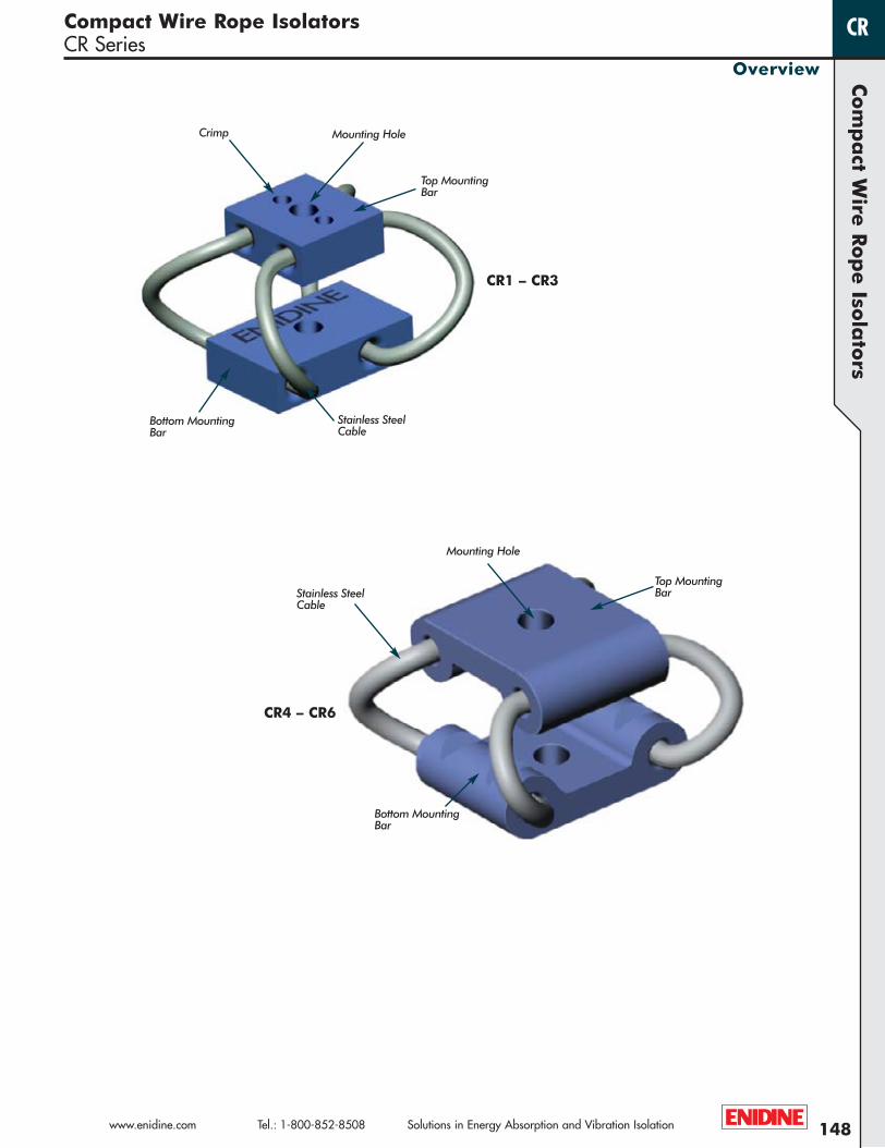
Crimp
Stainless SteelCable
Stainless SteelCable
Mounting Hole
Mounting Hole
Top MountingBar
Top MountingBar
Bottom MountingBar
Bottom MountingBar
CR1 – CR3
CR4 – CR6
WR Catalog 07 No Cover-Blue.qxp:WireRope-Cat.2007 4/13/11 9:45 AM Page 148

149
Compact Wire Rope IsolatorsCR Series
Overview
CR
Solutions in Energy Absorption and Vibration Isolation Tel.: 1-800-852-8508 www.enidine.com
Com
pa
ct W
ire R
op
e I
sola
tors
Performance:
Stiffness (Kv or Ks):Compact wire rope isolators exhibit non-linear stiffness behavior. Small deflections, usually associated with vibration isolation, willhave a different spring rate than larger shock deflections. Enidine publishes typical vibration stiffness values (Kv), and average shock stiffness values (Ks) within the catalog. These values can be used with the provided equations listed on Page 38 to predict system performance.
Isolator Axes:Compact wire rope isolators are multi-axis isolators. The diagram below includes load axis definitions and deflection considerations.
Damping: Typically 5-15%, depending on size and input level. For specific damping considerations, please consult Enidine.
Mounting Orientation:The diagrams below illustrate typical mounting orientations.
Stabilizers:Stabilizers are used to control deflections of tall supported masses. Stabilizers are typically recommended when the height equals 2-times the width or depth dimension. In most applications, the quantity of stabilizers required are half as many as the base isolators, and selected one size softer than the base isolators.
COMPRESSION FIXED ROLL/SHEAR45˚COMPRESSION/ROLL
COMPRESSION FIXED ROLL/SHEAR45˚COMPRESSION/ROLL
Materials and Finishes:
Standard: Wire Rope: 302/304 Stainless SteelMount Bars: 6061-T6 Aluminum, Chemical Conversion Coated per MIL-C-5541, Class 1AThreads: Tapped
Optional: Mount Bars: 6061-T6 Aluminum, Anodized per MIL-A-8625, Type II, Class 1302/304 Stainless Steel per ASTM A276, Passivated
Special: Consult Enidine
Isolator Options:
Mounting: Enidine offers a full range of mounting combinations of thru-hole, countersunk, and threaded bars. All configurations are available in either Imperial or Metric styles. Add an “M” after the mounting option for Metric. Some models have reduced mounting options available due to limited fastener installation space. Consult Enidine if a preferred mounting configuration is not listed.
Bellmouth: The bellmouth feature includes mount bars with radii manufactured into the wire rope hole edges. This option is recommended for high fatigue applications. Compact rope models (CR1 – CR6) include this feature as the standard.
WR Catalog 07 No Cover-Blue.qxp:WireRope-Cat.2007 4/13/11 9:45 AM Page 149
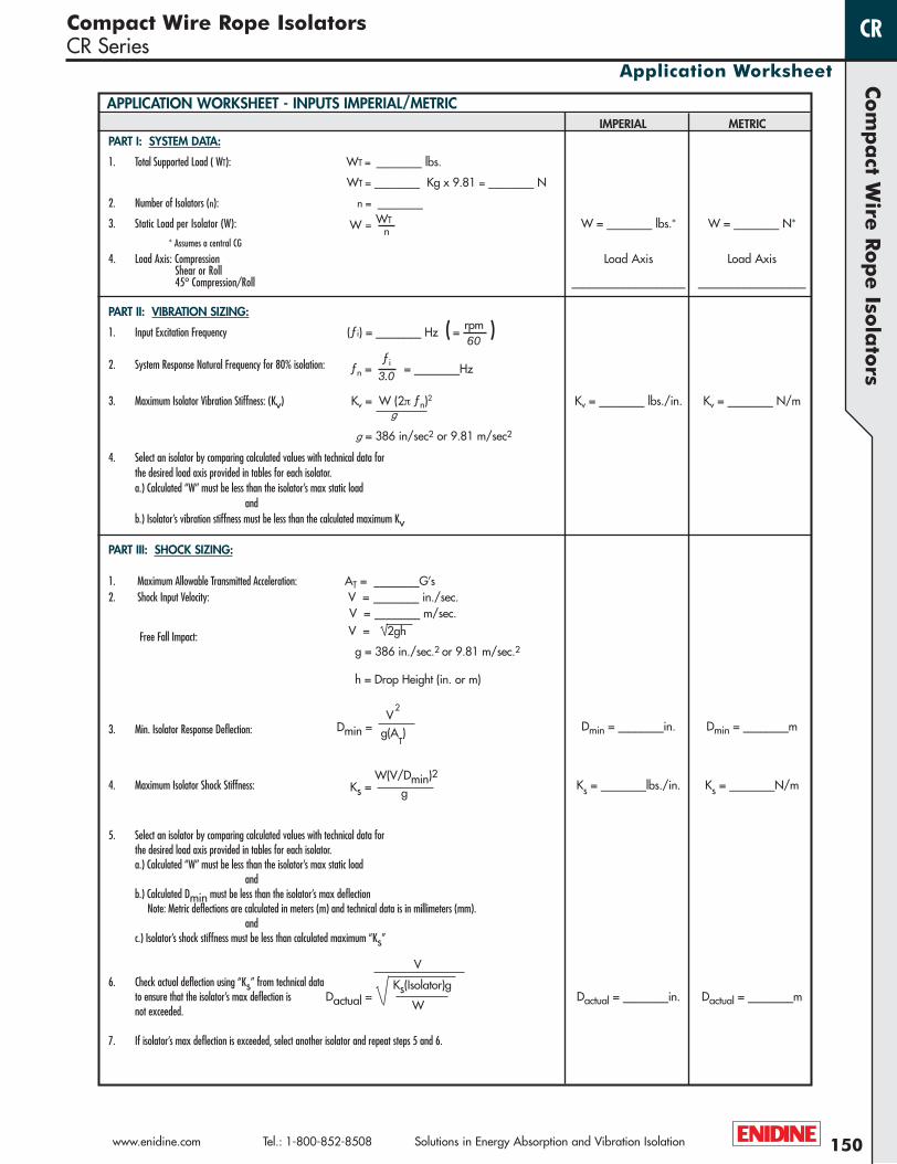
PART I: SYSTEM DATA:
1. Total Supported Load ( WT): WT = ________ lbs.
WT = ________ Kg x 9.81 = ________ N
2. Number of Isolators (n): n = ________
3. Static Load per Isolator (W): W = WT W = ________ lbs.* W = ________ N*
* Assumes a central CGn
4. Load Axis: Compression Load Axis Load AxisShear or Roll45º Compression/Roll ____________________ ___________________
PART II: VIBRATION SIZING:
1. Input Excitation Frequency (ƒi) = ________ Hz ( = rpm )2. System Response Natural Frequency for 80% isolation: ƒn =
ƒi = ________Hz3.0
3. Maximum Isolator Vibration Stiffness: (Kv) Kv = W (2π ƒn)2 Kv = ________ lbs./in. Kv = ________ N/mg
g = 386 in/sec2 or 9.81 m/sec2
4. Select an isolator by comparing calculated values with technical data forthe desired load axis provided in tables for each isolator.a.) Calculated “W” must be less than the isolator’s max static load
andb.) Isolator’s vibration stiffness must be less than the calculated maximum Kv
PART III: SHOCK SIZING:
1. Maximum Allowable Transmitted Acceleration: AT = ________G’s2. Shock Input Velocity: V = ________ in./sec.
V = ________ m/sec.
Free Fall Impact: V = 2gh
g = 386 in./sec.2 or 9.81 m/sec.2
h = Drop Height (in. or m)
3. Min. Isolator Response Deflection: Dmin = ________in. Dmin = ________m
4. Maximum Isolator Shock Stiffness: Ks = ________lbs./in. Ks = ________N/m
5. Select an isolator by comparing calculated values with technical data forthe desired load axis provided in tables for each isolator.a.) Calculated “W” must be less than the isolator’s max static load
andb.) Calculated Dmin must be less than the isolator’s max deflection
Note: Metric deflections are calculated in meters (m) and technical data is in millimeters (mm).and
c.) Isolator’s shock stiffness must be less than calculated maximum “Ks”
6. Check actual deflection using “Ks” from technical data to ensure that the isolator’s max deflection is Dactual = ________in. Dactual = ________mnot exceeded.
7. If isolator’s max deflection is exceeded, select another isolator and repeat steps 5 and 6.
150
Compact Wire Rope IsolatorsCR Series
Application Worksheet
CR
www.enidine.com Tel.: 1-800-852-8508 Solutions in Energy Absorption and Vibration Isolation
Com
pa
ct Wire
Rop
e Iso
lato
rs
Dmin =V
2
g(AT)
60
IMPERIAL METRIC
V
Dactual = Ks(Isolator)g
W
Ks =W(V/Dmin)2
g
APPLICATION WORKSHEET - INPUTS IMPERIAL/METRIC
WR Catalog 07 No Cover-Blue.qxp:WireRope-Cat.2007 4/13/11 9:45 AM Page 150

± .06(± 1,52)
.38(9,7)
.38(9,7)
.16 (4,1) TYP
“W” Ref.
“H”
.44(11,2)
.64(16,3)
ø.47(1,2) Ref.
S
A B C
D E
• Maximum recommended torque for tapped aluminum bar is 10 in.-lbs. (1,2 Nm)
• Wire Rope Material: Stranded 300 series stainless steel
• Operating Temperature Range: -150ºF to 500ºF ( -100ºC to 260ºC )
• U.S. Patent 6,290,217
C’sink C’sink Thread
Thru C’sink Thru
Thread C’sink Thru
Thread Thread Thru
Mounting Options
* Standard features. Any non-standard items may require longer lead times. Call for quotation.
Ø.130 #4-40 UNC 82ºA, B, C, D, E, S
(Ø3,30) (M3 X 0,5) (90º)
Note: Dimensions are in inches (mm)Tolerances are ± .010 (± .25mm)
151
Com
pa
ct W
ire R
op
e I
sola
tors
Compact Wire Rope IsolatorsCR1 Series
Solutions in Energy Absorption and Vibration Isolation Tel.: 1-800-852-8508 www.enidine.com
Technical Data
CR
Mount Bar Options: *[ ] - 6061-T6 AL ALY (or Equiv.)Chem Conv. Coated
[ Y ] - 6061-T6 AL ALY (or Equiv.)Anodized
[ P ] - 302/304 Stainless Steel (or Equiv.)Passivated
Add “M” for Metric For C’sink and Threaded Options
Mounting Options: See Chart
Isolator Size: See Sizing Table
CR1 - 400 - D M P
Model Number Ordering Code
Height Width (Ref) Unit Weight Mounting Thru Hole Thread C’sinkSize “H” “W” Lbs. Options in. in. Imperial
in. (mm) in. (mm) (Kg) (mm) (mm) (Metric)CR1-100 0.66 (17) 0.73 (19) 0.11 (3,1)CR1-200 0.75 (19) 0.79 (20) 0.11 (3,1)CR1-300 0.90 (23) 0.91 (23) 0.12 (3,4)CR1-400 1.04 (26) 1.03 (26) 0.12 (3,4)
.44 (11,2)
“W” (Ref)
“H” ø.47 (1,2)(Ref)
.16 (4,1)(Typ)
.38(9,7)
.38(9,7)
.64(16,3)
WR Catalog 07 No Cover-Blue.qxp:WireRope-Cat.2007 4/13/11 9:45 AM Page 151

1
2
3
4
1
2
3
4
1
2
3
4
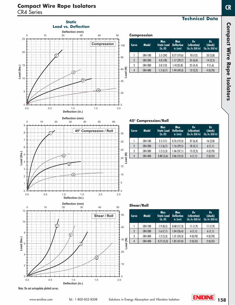
Note: Do not extrapolate plotted curves.
StaticLoad vs. Deflection
152
Com
pa
ct Wire
Rop
e Iso
lato
rs
www.enidine.com Tel.: 1-800-852-8508 Solutions in Energy Absorption and Vibration Isolation
Compact Wire Rope IsolatorsCR1 Series
Technical Data
CR
Max Max Kv KsCurve Model Static Load Deflection (vibration) (shock)
Lbs. (N) in. (mm) Lbs./in. (kN/m) Lbs./in. (kN/m)
1 CR1-100 0.75 (3,3) 0.25 (6,4) 22 (3,9) 11 (1,9)
2 CR1-200 0.55 (2,4) 0.33 (8,4) 16 (2,8) 7.0 (1,2)
3 CR1-300 0.40 (1,8) 0.47 (11,9) 10 (1,75) 3.5 (0,61)
4 CR1-400 0.30 (1,3) 0.59 (15,0) 7.5 (1,31) 2.2 (0,39)
Compression
45º Compression/Roll
Shear/Roll
Max Max Kv KsCurve Model Static Load Deflection (vibration) (shock)
Lbs. (N) in. (mm) Lbs./in. (kN/m) Lbs./in. (kN/m)
1 CR1-100 0.35 (1,6) 0.34 (8,6) 12 (2,1) 4.5 (0,79)
2 CR1-200 0.25 (1,1) 0.43 (10,9) 8.5 (1,5) 2.5 (0,44)
3 CR1-300 0.17 (0,76) 0.58 (14,7) 5.0 (0,88) 1.5 (0,26)
4 CR1-400 0.11 (0,49) 0.72 (18,3) 3.0 (0,53) 0.7 (0,12)
Max Max Kv KsCurve Model Static Load Deflection (vibration) (shock)
Lbs. (N) in. (mm) Lbs./in. (kN/m) Lbs./in. (kN/m)
1 CR1-100 0.25 (1,1) 0.31 (7,9) 4.0 (0,70) 4.0 (0,70)
2 CR1-200 0.20 (0,89) 0.39 (9,9) 2.5 (0,44) 2.5 (0,44)
3 CR1-300 0.16 (0,71) 0.52 (13,2) 1.5 (0,26) 1.5 (0,26)
4 CR1-400 0.12 (0,53) 0.64 (16,3) 0.8 (0,13) 0.8 (0,13)
WR Catalog 07 No Cover-Blue.qxp:WireRope-Cat.2007 4/13/11 9:45 AM Page 152

153
Com
pa
ct W
ire R
op
e I
sola
tors
Compact Wire Rope IsolatorsCR2 Series
Solutions in Energy Absorption and Vibration Isolation Tel.: 1-800-852-8508 www.enidine.com
Technical Data
CR
.38(9,7)
.38(9,7)
.16 (4,1) TYP
“W” Ref.
“H”
.44(11,2 )
.64(16,3)
ø.62(1,6) Ref.
± .06(± 1,52)
• Maximum recommended torque for tapped aluminum bar is 10 in.-lbs. (1,2 Nm)
• Wire Rope Material: Stranded 300 series stainless steel
• Operating Temperature Range: -150ºF to 500ºF ( -100ºC to 260ºC )
• U.S. Patent 6,290,217
Ø.130 #4-40 UNC 82ºA, B, C, D, E, S
(Ø3.30) (M3 X 0,5) (90º)
Note: Dimensions are in inches (mm)Tolerances are ± .010 (± .25mm)
S
A B C
D E
C’sink C’sink Thread
Thru C’sink Thru
Thread C’sink Thru
Thread Thread Thru
Mounting OptionsModel Number Ordering Code
Height Width (Ref) Unit Weight Mounting Thru Hole Thread C’sinkSize “H” “W” Lbs. Options in. in. Imperial
in. (mm) in. (mm) (Kg) (mm) (mm) (Metric)CR2-100 0.64 (16) 0.78 (20) 0.13 (3,7)CR2-200 0.75 (19) 0.83 (21) 0.14 (4,0)CR2-300 0.89 (23) 0.94 (24) 0.15 (4,3)CR2-400 1.07 (27) 1.06 (27) 0.16 (4,5)
.44 (11,2)
“W” (Ref)
“H”ø.62 (1,6)(Ref)
.16 (4,1)(Typ)
.38(9,7)
.38(9,7)
.64(16,3)
* Standard features. Any non-standard items may require longer lead times. Call for quotation.
Mount Bar Options: *[ ] - 6061-T6 AL ALY (or Equiv.)Chem Conv. Coated
[ Y ] - 6061-T6 AL ALY (or Equiv.)Anodized
[ P ] - 302/304 Stainless Steel (or Equiv.)Passivated
Add “M” for Metric For C’sink and Threaded Options
Mounting Options: See Chart
Isolator Size: See Sizing Table
CR2 - 400 - D M P
WR Catalog 07 No Cover-Blue.qxp:WireRope-Cat.2007 4/13/11 9:45 AM Page 153

154
Com
pa
ct Wire
Rop
e Iso
lato
rs
www.enidine.com Tel.: 1-800-852-8508 Solutions in Energy Absorption and Vibration Isolation
Compact Wire Rope IsolatorsCR2 Series
Technical Data
CR
1
2
3
4
1
2
3
4
1
2
3
4
Note: Do not extrapolate plotted curves.
StaticLoad vs. Deflection
Max Max Kv KsCurve Model Static Load Deflection (vibration) (shock)
Lbs. (N) in. (mm) Lbs./in. (kN/m) Lbs./in. (kN/m)
1 CR2-100 2.6 (12) 0.23 (5,8) 65 (11) 35 (6,1)
2 CR2-200 2.1 (9,3) 0.33 (8,4) 50 (8,8) 23 (4,0)
3 CR2-300 1.5 (6,7) 0.46 (11,7) 30 (5,3) 11 (1,9)
4 CR2-400 1.1 (4,9) 0.62 (15,7) 20 (3,5) 7 (1,2)
Compression
45º Compression/Roll
Shear/Roll
Max Max Kv KsCurve Model Static Load Deflection (vibration) (shock)
Lbs. (N) in. (mm) Lbs./in. (kN/m) Lbs./in. (kN/m)
1 CR2-100 1.3 (5,8) 0.32 (8,1) 35 (6,1) 16 (2,8)
2 CR2-200 1.1 (4,9) 0.43 (10,9) 30 (5,3) 11 (1,9)
3 CR2-300 0.75 (3,3) 0.57 (14,5) 18 (3,2) 6 (1,0)
4 CR2-400 0.50 (2,2) 0.75 (19,1) 11 (1,9) 3 (0,51)
Max Max Kv KsCurve Model Static Load Deflection (vibration) (shock)
Lbs. (N) in. (mm) Lbs./in. (kN/m) Lbs./in. (kN/m)
1 CR2-100 1.3 (5,6) 0.29 (7,4) 17 (3,0) 17 (3,0)
2 CR2-200 0.90 (4,0) 0.39 (9,9) 10 (1,8) 10 (1,8)
3 CR2-300 0.65 (2,9) 0.51 (13,0) 6 (1,1) 6 (1,1)
4 CR2-400 0.45 (2,0) 0.68 (17,3) 3 (0,53) 3 (0,53)
WR Catalog 07 No Cover-Blue.qxp:WireRope-Cat.2007 4/13/11 9:45 AM Page 154

Height Width (Ref) Unit Weight Mounting Thru Hole Thread C’sinkSize “H” “W” Lbs. Options in. in. Imperial
in. (mm) in. (mm) (Kg) (mm) (mm) (Metric)CR3-100 0.75 (19) 0.88 (22) 0.20 (5,7)CR3-200 0.90 (23) 0.95 (24) 0.22 (6,2)CR3-300 1.06 (27) 1.06 (27) 0.24 (6,8)CR3-400 1.28 (33) 1.20 (30) 0.26 (7,4)
± .06(± 1,52)
Ø.130 #4-40 UNC 82ºA, B, C, D, E, S
(Ø3,30) (M3 X 0,5) (90º)
ø.094(2,4) Ref.
.19(4,8)Typ.
.50(12,7)
.38(9,7)
.76(19,3)
.38(9,7)
“W” Ref.
“H”
• Maximum recommended torque for tapped aluminum bar is 13 in.-lbs. (1,5 Nm)
• Wire Rope Material: Stranded 300 series stainless steel
• Operating Temperature Range: -150ºF to 500ºF ( -100ºC to 260ºC )
• U.S. Patent 6,290,217
Note: Dimensions are in inches (mm)Tolerances are ± .010 (± .25mm)
S
A B C
D E
C’sink C’sink Thread
Thru C’sink Thru
Thread C’sink Thru
Thread Thread Thru
Mounting Options
155
Com
pa
ct W
ire R
op
e I
sola
tors
Compact Wire Rope IsolatorsCR3 Series
Solutions in Energy Absorption and Vibration Isolation Tel.: 1-800-852-8508 www.enidine.com
Technical Data
CR
Model Number Ordering Code
.50(12,7)
“W” (Ref)
“H”ø0.94 (2,4)(Ref)
.19 (4,8)(Typ)
.38(9,7)
.38(9,7)
.76(19,3)
* Standard features. Any non-standard items may require longer lead times. Call for quotation.
Mount Bar Options: *[ ] - 6061-T6 AL ALY (or Equiv.)Chem Conv. Coated
[ Y ] - 6061-T6 AL ALY (or Equiv.)Anodized
[ P ] - 302/304 Stainless Steel (or Equiv.)Passivated
Add “M” for Metric For C’sink and Threaded Options
Mounting Options: See Chart
Isolator Size: See Sizing Table
CR3 - 400 - D M P
WR Catalog 07 No Cover-Blue.qxp:WireRope-Cat.2007 4/13/11 9:45 AM Page 155

1
2
3
4
1
2
3
4
1
2
3
4
Note: Do not extrapolate plotted curves.
StaticLoad vs. Deflection
156
Com
pa
ct Wire
Rop
e Iso
lato
rs
www.enidine.com Tel.: 1-800-852-8508 Solutions in Energy Absorption and Vibration Isolation
Compact Wire Rope IsolatorsCR3 Series
Technical Data
CR
Max Max Kv KsCurve Model Static Load Deflection (vibration) (shock)
Lbs. (N) in. (mm) Lbs./in. (kN/m) Lbs./in. (kN/m)
1 CR3-100 6.5 (29) 0.28 (7,1) 135 (24) 68 (12)
2 CR3-200 5.0 (22) 0.41 (10,4) 70 (12) 35 (6,1)
3 CR3-300 4.0 (18) 0.56 (14,2) 48 (8,4) 20 (3,5)
4 CR3-400 2.5 (11) 0.76 (19,3) 33 (5,8) 11 (1,9)
Compression
45º Compression/Roll
Shear/Roll
Max Max Kv KsCurve Model Static Load Deflection (vibration) (shock)
Lbs. (N) in. (mm) Lbs./in. (kN/m) Lbs./in. (kN/m)
1 CR3-100 2.7 (12) 0.37 (9,4) 80 (14) 30 (5,3)
2 CR3-200 2.3 (10) 0.52 (13,2) 50 (8,8) 18 (3,2)
3 CR3-300 1.5 (6,7) 0.68 (17,3) 33 (5,8) 10 (1,8)
4 CR3-400 1.0 (4,4) 0.90 (22,9) 20 (3,5) 5 (0,91)
Max Max Kv KsCurve Model Static Load Deflection (vibration) (shock)
Lbs. (N) in. (mm) Lbs./in. (kN/m) Lbs./in. (kN/m)
1 CR3-100 2.7 (12) 0.33 (8,4) 35 (6,1) 35 (6,1)
2 CR3-200 1.9 (8,5) 0.47 (11,9) 20 (3,5) 20 (3,5)
3 CR3-300 1.4 (6,2) 0.61 (15,5) 10 (1,8) 10 (1,8)
4 CR3-400 1.0 (4,4) 0.81 (20,6) 6 (1,1) 6 (1,1)
WR Catalog 07 No Cover-Blue.qxp:WireRope-Cat.2007 4/13/11 9:45 AM Page 156

Height Width (Ref) Unit Weight Mounting Thru Hole Thread C’sinkSize “H” “W” Lbs. Options in. in. Imperial
in. (mm) in. (mm) (Kg) (mm) (mm) (Metric)CR4-100 1.66 (42) 1.87 (47) 1.4 (40)CR4-200 2.10 (53) 2.12 (54) 1.4 (40)CR4-300 2.37 (60) 2.34 (59) 1.5 (43)CR4-400 2.96 (75) 2.67 (68) 1.7 (48)
1.00(25,4)
.37 (9,4)
“W” Ref.
“H”
1.34(34,0)
.20 (5,1)
ø.125 (3,2) Ref.
± .06(± 1,52)
S
A B C
D E
• Maximum recommended torque for tapped aluminum bar is 40 in.-lbs. (7,5 Nm)
• Wire Rope Material: Stranded 300 series stainless steel
• Operating Temperature Range: -150ºF to 500ºF ( -100ºC to 260ºC )
• U.S. Patent 6,244,579
Thru C’sink Thru
C’sink C’sink Thread
Thread Thread Thru
Thread C’sink Thru
Mounting Options
Ø.230 #10-32 UNF 82ºA, B, C, D, E, S
(Ø7,00) (M6 X 1,0) (90º)
Note: Dimensions are in inches (mm)Tolerances are ± .010 (± .25mm)
157
Com
pa
ct W
ire R
op
e I
sola
tors
Compact Wire Rope IsolatorsCR4 Series
Solutions in Energy Absorption and Vibration Isolation Tel.: 1-800-852-8508 www.enidine.com
Technical Data
CR
Model Number Ordering Code
1.34 (34,0)
“W” (Ref)
“H”ø.125 (3,2)(Ref)
1.00(25,4)
.20 (5,1)
.37 (9,4)
* Standard features. Any non-standard items may require longer lead times. Call for quotation.
Mount Bar Options: *[ ] - 6061-T6 AL ALY (or Equiv.)Chem Conv. Coated
[ Y ] - 6061-T6 AL ALY (or Equiv.)Anodized
[ P ] - 302/304 Stainless Steel (or Equiv.)Passivated
Add “M” for Metric All Mounting Options
Mounting Options: See Chart
Isolator Size: See Sizing Table
CR4 - 400 - D M P
WR Catalog 07 No Cover-Blue.qxp:WireRope-Cat.2007 4/13/11 9:45 AM Page 157
1
2
3
4
1
2
3
4
1
2
3
4
Note: Do not extrapolate plotted curves.
StaticLoad vs. Deflection
158
Com
pa
ct Wire
Rop
e Iso
lato
rs
www.enidine.com Tel.: 1-800-852-8508 Solutions in Energy Absorption and Vibration Isolation
Compact Wire Rope IsolatorsCR4 Series
Technical Data
CR
Max Max Kv KsCurve Model Static Load Deflection (vibration) (shock)
Lbs. (N) in. (mm) Lbs./in. (kN/m) Lbs./in. (kN/m)
1 CR4-100 5.5 (24) 0.77 (19,6) 70 (12) 33 (5,8)
2 CR4-200 4.0 (18) 1.17 (29,7) 35 (6,0) 14 (2,5)
3 CR4-300 3.0 (13) 1.41(35,8) 25 (4,4) 9 (1,6)
4 CR4-400 1.5 (6.7) 1.94 (49,3) 12 (2,2) 4 (0,70)
Compression
45º Compression/Roll
Shear/Roll
Max Max Kv KsCurve Model Static Load Deflection (vibration) (shock)
Lbs. (N) in. (mm) Lbs./in. (kN/m) Lbs./in. (kN/m)
1 CR4-100 2.5 (11) 0.76 (19,3) 37 (6,4) 16 (2,8)
2 CR4-200 1.5 (6,7) 1.16 (29,5) 18 (3,1) 6 (1,1)
3 CR4-300 1.2 (5,3) 1.46 (37,1) 13 (2,2) 4 (0,70)
4 CR4-400 0.80 (3,6) 2.06 (52,3) 6 (1,1) 2 (0,35)
Max Max Kv KsCurve Model Static Load Deflection (vibration) (shock)
Lbs. (N) in. (mm) Lbs./in. (kN/m) Lbs./in. (kN/m)
1 CR4-100 1.9 (8,5) 0.68 (17,3) 11 (1,9) 11 (1,9)
2 CR4-200 1.6 (7,1) 1.04 (26,4) 6 (1,1) 6 (1,1)
3 CR4-300 1.2 (5,3) 1.31 (33,3) 4 (0,70) 4 (0,70)
4 CR4-400 0.75 (3,3) 1.85 (47,0) 2 (0,35) 2 (0,35)
WR Catalog 07 No Cover-Blue.qxp:WireRope-Cat.2007 4/13/11 9:45 AM Page 158
1.00(25,4)
.39 (9,9)
“W” Ref.
“H”
1.38(35,1)
.20 (5,1)
ø.156 (4,0) Ref.
± .06(± 1,52)
S
A B C
D E
• Maximum recommended torque for tapped aluminum bar is 40 in.-lbs. (7,5 Nm)
• Wire Rope Material: Stranded 300 series stainless steel
• Operating Temperature Range: -150ºF to 500ºF ( -100ºC to 260ºC )
• U.S. Patent 6,244,579
Thru C’sink Thru
C’sink C’sink Thread
Thread Thread Thru
Thread C’sink Thru
Mounting Options
Ø.230 #10-32 UNF 82ºA, B, C, D, E, S
(Ø7,00) (M6 X 1,0) (90º)
Note: Dimensions are in inches (mm)Tolerances are ± .010 (± .25mm)
159
Com
pa
ct W
ire R
op
e I
sola
tors
Compact Wire Rope IsolatorsCR5 Series
Solutions in Energy Absorption and Vibration Isolation Tel.: 1-800-852-8508 www.enidine.com
Technical Data
CR
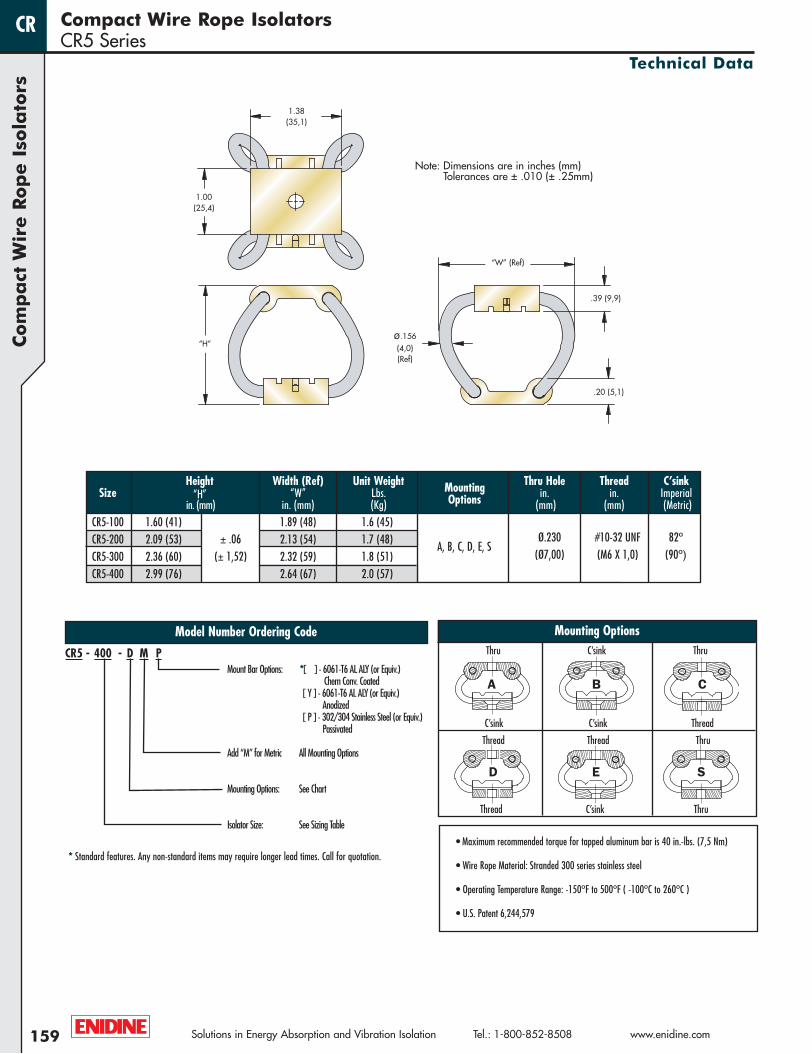
Model Number Ordering Code
Height Width (Ref) Unit Weight Mounting Thru Hole Thread C’sinkSize “H” “W” Lbs. Options in. in. Imperial
in. (mm) in. (mm) (Kg) (mm) (mm) (Metric)CR5-100 1.60 (41) 1.89 (48) 1.6 (45)CR5-200 2.09 (53) 2.13 (54) 1.7 (48)CR5-300 2.36 (60) 2.32 (59) 1.8 (51)CR5-400 2.99 (76) 2.64 (67) 2.0 (57)
1.38 (35,1)
“W” (Ref)
“H”ø.156 (4,0)(Ref)
1.00(25,4)
.20 (5,1)
.39 (9,9)
* Standard features. Any non-standard items may require longer lead times. Call for quotation.
Mount Bar Options: *[ ] - 6061-T6 AL ALY (or Equiv.)Chem Conv. Coated
[ Y ] - 6061-T6 AL ALY (or Equiv.)Anodized
[ P ] - 302/304 Stainless Steel (or Equiv.)Passivated
Add “M” for Metric All Mounting Options
Mounting Options: See Chart
Isolator Size: See Sizing Table
CR5 - 400 - D M P
WR Catalog 07 No Cover-Blue.qxp:WireRope-Cat.2007 4/13/11 9:45 AM Page 159
1
2
3
4
1
2
3
4
1
2
3
4
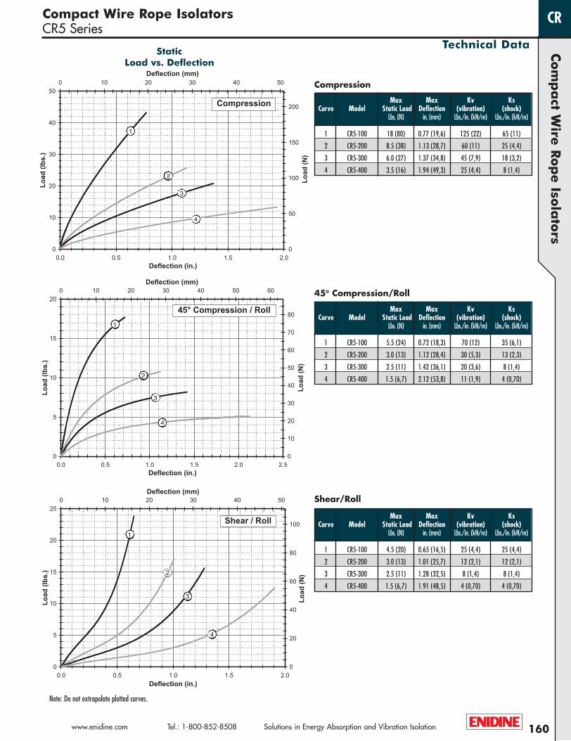
Note: Do not extrapolate plotted curves.
StaticLoad vs. Deflection
160
Com
pa
ct Wire
Rop
e Iso
lato
rs
www.enidine.com Tel.: 1-800-852-8508 Solutions in Energy Absorption and Vibration Isolation
Compact Wire Rope IsolatorsCR5 Series
Technical Data
CR
Max Max Kv KsCurve Model Static Load Deflection (vibration) (shock)
Lbs. (N) in. (mm) Lbs./in. (kN/m) Lbs./in. (kN/m)
1 CR5-100 18 (80) 0.77 (19,6) 125 (22) 65 (11)
2 CR5-200 8.5 (38) 1.13 (28,7) 60 (11) 25 (4,4)
3 CR5-300 6.0 (27) 1.37 (34,8) 45 (7,9) 18 (3,2)
4 CR5-400 3.5 (16) 1.94 (49,3) 25 (4,4) 8 (1,4)
Compression
45º Compression/Roll
Shear/Roll
Max Max Kv KsCurve Model Static Load Deflection (vibration) (shock)
Lbs. (N) in. (mm) Lbs./in. (kN/m) Lbs./in. (kN/m)
1 CR5-100 5.5 (24) 0.72 (18,3) 70 (12) 35 (6,1)
2 CR5-200 3.0 (13) 1.12 (28,4) 30 (5,3) 13 (2,3)
3 CR5-300 2.5 (11) 1.42 (36,1) 20 (3,6) 8 (1,4)
4 CR5-400 1.5 (6,7) 2.12 (53,8) 11 (1,9) 4 (0,70)
Max Max Kv KsCurve Model Static Load Deflection (vibration) (shock)
Lbs. (N) in. (mm) Lbs./in. (kN/m) Lbs./in. (kN/m)
1 CR5-100 4.5 (20) 0.65 (16,5) 25 (4,4) 25 (4,4)
2 CR5-200 3.0 (13) 1.01 (25,7) 12 (2,1) 12 (2,1)
3 CR5-300 2.5 (11) 1.28 (32,5) 8 (1,4) 8 (1,4)
4 CR5-400 1.5 (6,7) 1.91 (48,5) 4 (0,70) 4 (0,70)
WR Catalog 07 No Cover-Blue.qxp:WireRope-Cat.2007 4/13/11 9:45 AM Page 160

1.41(35,8)
1.00(25,4)
.40 (10,2)
“W” Ref.
“H”
.20 (5,1)
ø.188 (4,8) Ref.
± .06(± 1,52)
S
A B C
D E
• Maximum recommended torque for tapped aluminum bar is 40 in.-lbs. (7,5 Nm)
• Wire Rope Material: Stranded 300 series stainless steel
• Operating Temperature Range: -150ºF to 500ºF ( -100ºC to 260ºC )
• U.S. Patent 6,244,579
Thru C’sink Thru
C’sink C’sink Thread
Thread Thread Thru
Thread C’sink Thru
Mounting Options
Ø.230 #10-32 UNF 82ºA, B, C, D, E, S
(Ø7,00) (M6 X 1,0) (90º)
Note: Dimensions are in inches (mm)Tolerances are ± .010 (± .25mm)
161
Com
pa
ct W
ire R
op
e I
sola
tors
Compact Wire Rope IsolatorsCR6 Series
Solutions in Energy Absorption and Vibration Isolation Tel.: 1-800-852-8508 www.enidine.com
Technical Data
CR
Model Number Ordering Code
Height Width (Ref) Unit Weight Mounting Thru Hole Thread C’sinkSize “H” “W” Lbs. Options in. in. Imperial
in. (mm) in. (mm) (Kg) (mm) (mm) (Metric)CR6-100 1.83 (47) 2.11 (54) 2.0 (57)CR6-200 2.15 (55) 2.31 (59) 2.2 (62)CR6-300 2.51 (64) 2.50 (64) 2.3 (65)CR6-400 3.09 (79) 2.86 (73) 2.6 (74)
1.41 (35,8)
“W” (Ref)
“H”ø.188 (4,8)(Ref)
1.00(25,4)
.20 (5,1)
.40 (10,2)
* Standard features. Any non-standard items may require longer lead times. Call for quotation.
Mount Bar Options: *[ ] - 6061-T6 AL ALY (or Equiv.)Chem Conv. Coated
[ Y ] - 6061-T6 AL ALY (or Equiv.)Anodized
[ P ] - 302/304 Stainless Steel (or Equiv.)Passivated
Add “M” for Metric All Mounting Options
Mounting Options: See Chart
Isolator Size: See Sizing Table
CR6 - 400 - D M P
WR Catalog 07 No Cover-Blue.qxp:WireRope-Cat.2007 4/13/11 9:45 AM Page 161
1
2
3
4
1
2
3
4
1
2
3
4
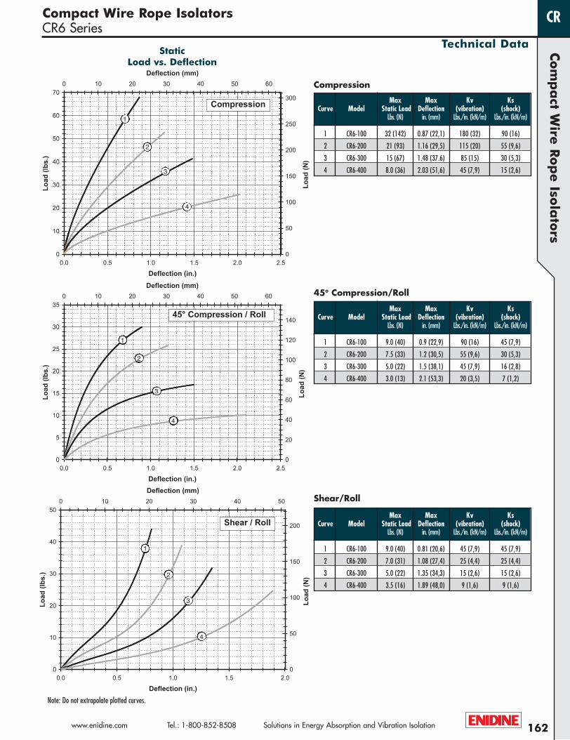
Note: Do not extrapolate plotted curves.
StaticLoad vs. Deflection
162
Com
pa
ct Wire
Rop
e Iso
lato
rs
www.enidine.com Tel.: 1-800-852-8508 Solutions in Energy Absorption and Vibration Isolation
Compact Wire Rope IsolatorsCR6 Series
Technical Data
CR
Max Max Kv KsCurve Model Static Load Deflection (vibration) (shock)
Lbs. (N) in. (mm) Lbs./in. (kN/m) Lbs./in. (kN/m)
1 CR6-100 32 (142) 0.87 (22,1) 180 (32) 90 (16)
2 CR6-200 21 (93) 1.16 (29,5) 115 (20) 55 (9,6)
3 CR6-300 15 (67) 1.48 (37.6) 85 (15) 30 (5,3)
4 CR6-400 8.0 (36) 2.03 (51,6) 45 (7,9) 15 (2,6)
Compression
45º Compression/Roll
Shear/Roll
Max Max Kv KsCurve Model Static Load Deflection (vibration) (shock)
Lbs. (N) in. (mm) Lbs./in. (kN/m) Lbs./in. (kN/m)
1 CR6-100 9.0 (40) 0.9 (22,9) 90 (16) 45 (7,9)
2 CR6-200 7.5 (33) 1.2 (30,5) 55 (9,6) 30 (5,3)
3 CR6-300 5.0 (22) 1.5 (38,1) 45 (7,9) 16 (2,8)
4 CR6-400 3.0 (13) 2.1 (53,3) 20 (3,5) 7 (1,2)
Max Max Kv KsCurve Model Static Load Deflection (vibration) (shock)
Lbs. (N) in. (mm) Lbs./in. (kN/m) Lbs./in. (kN/m)
1 CR6-100 9.0 (40) 0.81 (20,6) 45 (7,9) 45 (7,9)
2 CR6-200 7.0 (31) 1.08 (27,4) 25 (4,4) 25 (4,4)
3 CR6-300 5.0 (22) 1.35 (34,3) 15 (2,6) 15 (2,6)
4 CR6-400 3.5 (16) 1.89 (48,0) 9 (1,6) 9 (1,6)
WR Catalog 07 No Cover-Blue.qxp:WireRope-Cat.2007 4/13/11 9:45 AM Page 162


