Communications:More Issues Out There
ECE 4600Dr. Bradley J. Bazuin

Communications System• Analog or Digital Communications
– Information Message Type (Analog or Digital)– Modulation Type (Discrete or Continuous)
• Terminology– Message, Symbol, Signal, Noise
Information Message Format Encoding/
Encryption Modulation RF Mixing Transmitter
Reformat dencoding/dencryption Demodulation RF Mixing Receiver
Antenna
AntennaInformation Message
RF Signal
Noise
Interference
2

Common Frequencies• AM Radio: 535-1705 kHz• FM Radio: 88-108 MHz• ISM: 433.05-434.79 and 902-928 MHz• ISM: 2.4-2.5 GHz (wireless Ethernet & Bluetooth)• ISM: 5.725-5.875 GHz (wireless Ethernet)• Cell : 824-849 and 869-894 MHz• PCS: 1850-1910 and 1930-1990 MHz• AWS: 1710-1755 and 2110-2155 MHz• BRS/EBS: 2.496–2.690 GHz• More Frequencies
– https://en.wikipedia.org/wiki/Cellular_frequencies– https://en.wikipedia.org/wiki/ISM_band
3

Digital Signal ModulationBasic forms
• Amplitude Shift Keying (M-ASK)• Phase Shift Keying (M-PSK)• Frequency Shift Keying (M-FSK)
– Continuous Phase FSK (CP-FSK)– Gaussian Minimum Shift Keying
(GMSK)• Quadrature Amplitude Modulation
(QAM)
Advanced Forms
• Trellis-Code Modulation (TCM)– Include error correction with the
modulation. Reed-Solomon codes and Viterbi decode.
• Orthogonal Frequency Division Modulation (OFDM)
• Direct Sequence Spread Spectrum (DSSS)– Code Division Multiple Access
(CDMA)• Frequency Hopping (FH)
– fast or slow rates
4
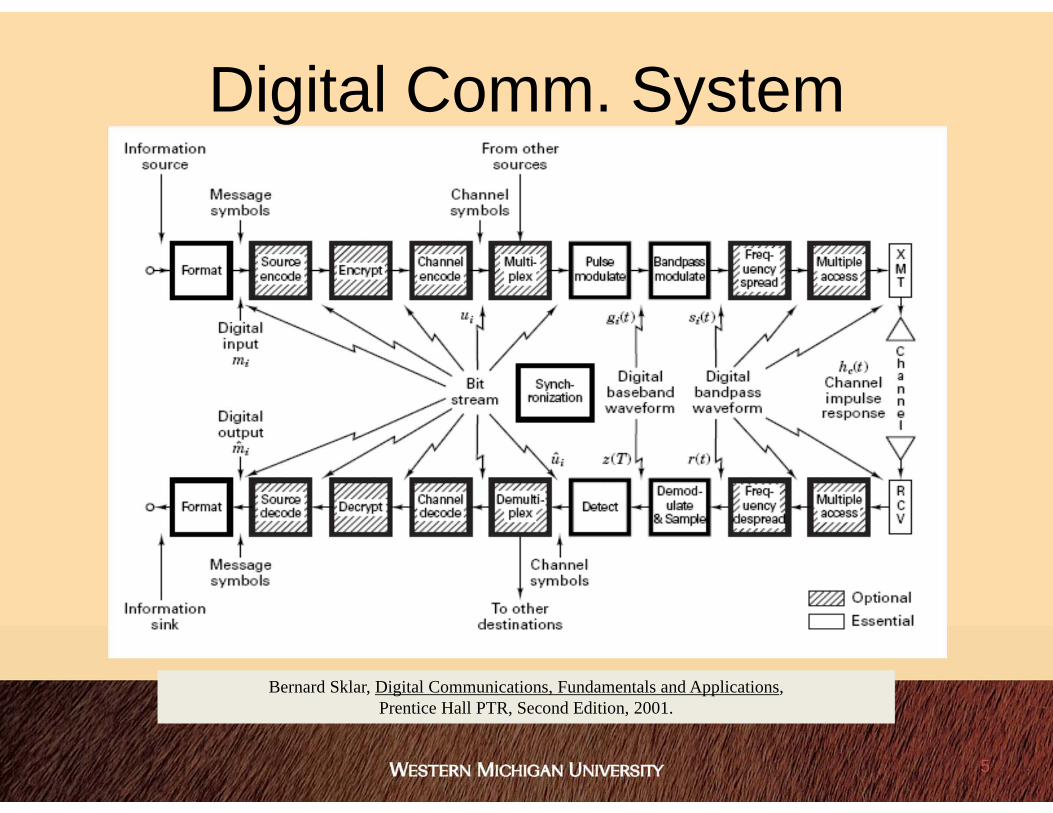
Digital Comm. System
Bernard Sklar, Digital Communications, Fundamentals and Applications, Prentice Hall PTR, Second Edition, 2001.
5

Signal Processing Functions
Bernard Sklar, Digital Communications, Fundamentals and Applications, Prentice Hall PTR, Second Edition, 2001.
6

Trellis-Coded Modulation (TCM)• Developing combined modulation and coding schemes• Use a redundant nonbinary modulation in combination with a
finite-state machine based encoding process.– FSM could be similar to convolutional encoding– A multi-level/phase modulation scheme
• The concept, when performing MATLAB simulations of encoded bit streams using MPSK or QAM symbols, is there an optimal combination? – if you know the symbols being used, could one convolutional code
leading to an appropriate trellis decoding perform better than another? Yes!
7

TCM Encoding• Ungerboeck, G., "Channel coding with
multilevel/phase signals," Information Theory, IEEE Transactions on, vol.28, no.1, pp.55,67, Jan 1982.
• Initial paper describing trellis coded, soft decision encoding and modulation technique for communications.
8

Orthogonal Frequency Division Multiplexing (OFDM)
• Multiplexing in both phase and frequency domains– Without the costly hardware of conventional FDM– Can be implemented using IFFT/FFT hardware
• OFDM form of Multicarrier (MC) modulation– Carriers are mutual orthogonal
• We parse up a given message into separate components to OFDM them onto a channel
a symbol is transmitted at a lower rate increased immunity to multipath may not have to employ equalization
9

Applications• IEEE 802.11 (Wi-Fi) and IEEE-802.16 (WiMax)• Modems, DSLs• 4G Cellular Phones
– LTE and LTE Advanced Cellular Telephone
• OFDM system of parsing symbols onto separate frequencies and phases can be extended to multiple access (MA) applications.
10
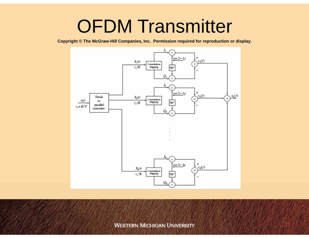
OFDM TransmitterCopyright © The McGraw-Hill Companies, Inc. Permission required for reproduction or display.
11
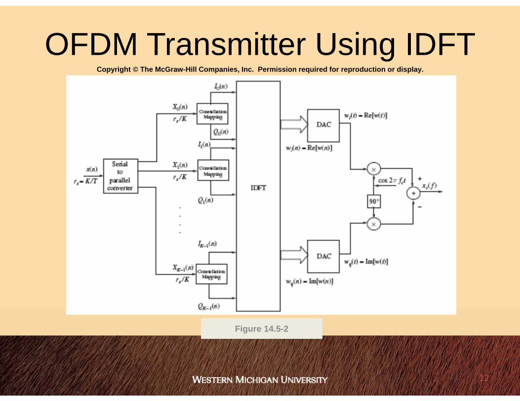
OFDM Transmitter Using IDFT
Figure 14.5-2
Copyright © The McGraw-Hill Companies, Inc. Permission required for reproduction or display.
12

OFDM Modulator
fred haris, Orthogonal Frequency Division Multiplexing OFDM, Vehicular Technology Conference - 2004
13

OFDM Demodulator
fred haris, Orthogonal Frequency Division Multiplexing OFDM, Vehicular Technology Conference - 2004
14

OFDM is a Block Process
fred haris, Orthogonal Frequency Division Multiplexing OFDM, Vehicular Technology Conference - 2004
15

Spread Spectrum Systems• There are two principal types of spread
spectrum systems:– Frequency Hopping (FH-SS)
• Blue tooth, GSM Cell Phones, Radios– Direct Sequence Spread Spectrum (DSS)
• GPS, CDMA Cell Phones
16

DSS Signaling• Binary Symbols {+1, -1} multiplied by a
chipping code consisting of a pseudo-random binary symbol sequence.
– The symbol modulates a lengthy chip sequence by +/- 1.
– But multiplying by the chip sequence again the original signal returns.
tctxtxDSS
tctxtxtctxtx DSSDSS
17

Autocorrelation• If we transmit the DSS signal, there is a time delay
due to distance. Thus, we must time align the received DSS with the chip sequence in order to receive it.Tc
A2
Tc-Tc
NTc-NTc
R() = A2 (1 - | | / Tc) for | | Tc= - A2 /N elsewhere
18
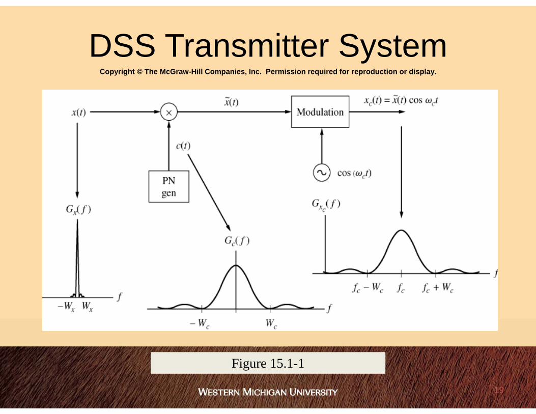
Copyright © The McGraw-Hill Companies, Inc. Permission required for reproduction or display.
Figure 15.1-1
DSS Transmitter System
19
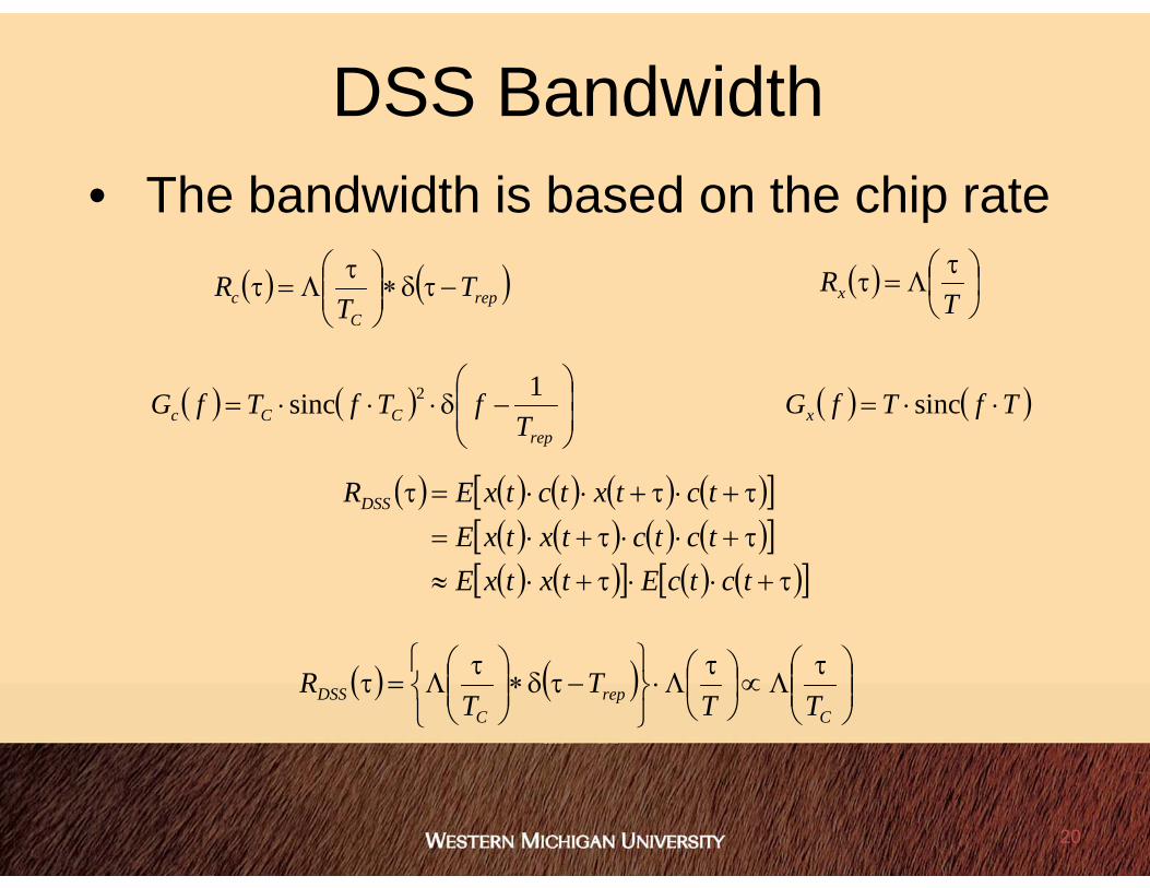
DSS Bandwidth• The bandwidth is based on the chip rate
repC
c TT
R
repCCc T
fTfTfG 1sinc 2
T
Rx
TfTfGx sinc
tctcEtxtxEtctctxtxEtctxtctxERDSS
Crep
CDSS TT
TT
R
20

Bandwidth Expansion Factor• For DS spreading of the signal, the bandwidth has
gone from 1/T to 1/Tc
b
C
C
bBWex W
WTTg
21

Correlation Receiver• Use the PN sequence as an optimal “filter” or
correlator sequence
22
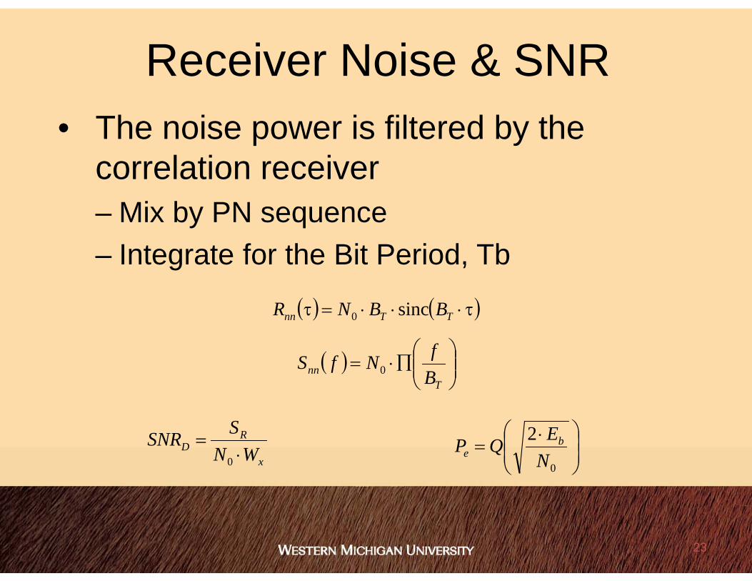
Receiver Noise & SNR• The noise power is filtered by the
correlation receiver– Mix by PN sequence– Integrate for the Bit Period, Tb
TTnn BBNR sinc0
Tnn B
fNfS 0
x
RD WN
SSNR
0
0
2NEQP b
e
23

Copyright © The McGraw-Hill Companies, Inc. Permission required for reproduction or display.
Figure 15.1-2
DSS Inherent Anti-Jam
24

GPS Signal Characteristics• Two Principal Frequencies
– L1 Band at 1575.42 MHz with C/A and P(Y) codes– L2 Band at 1227.60 MHz with P(Y) code– L5 Band at 1176.45 MHz with “new” C/A code
• Direct Sequence Spread Spectrum Communications– Data Message at 50 bps consisting of 1500 bit pages (30 sec.)– C/A-code spreads the data using 1023-bit Gold codes at a chipping
rate of 1.023 Mcps (C/A – coarse-acquisition code)– P(Y)-code spreads the data using a code that Does not repeat at a
chipping rate of 1.0.23 Mcps (P – precision code)• Code Transmission
– The C/A- and P(Y)-codes are transmitted in quadrature on L1– The P(Y)-code is transmitted on L2
25

GPS Receiver Characteristics• Receive up to 12 satellites simultaneously• User Minimum received power
– L1 C/A-Code:–130 dBm– L1 P-Code: –133 dBm– L2 P-Code: –136 dBm– kTB (20 MHz): –101 dBm
-10 -5 0 5 10-160
-150
-140
-130
-120
-110
-100
dBm
/ H
z
Frequancy (MHz)
Thermal Noise PowerC/A Code P(Y) Code
26

GPS User Position Computation• GPS uses the triangulation of signals from
the satellites to determine locations on earth. • GPS satellites know their location in space
and receivers can determine their distance from a satellite by using the travel time of a radio message from the satellite to the receiver.
• After calculating its relative position to at least 4 satellites, a GPS receiver can calculate its position using triangulation.
• They also have a database (or almanac) of the current and expected positions for all of the satellites that is frequently updated from earth.
Earth
Satellite
r
u
s
SV to User Distancer = || s – u ||r = c x t
Measured Pseudorange = r + c x tu
Unknownsr(x, y, z), tUse 4 SVs to solve
27

Copyright © The McGraw-Hill Companies, Inc. Permission required for reproduction or display.
Figure 15.2-1
(a) Transmit
(b) Receive
FH-SS System.
28

Copyright © The McGraw-Hill Companies, Inc. Permission required for reproduction or display.
Figure 15.2-2
Output frequency versus data input for slow hop FH-SS system
Waterfall Displays: allow frequencies in time to be observed
29


