
Colouran algorithmic approach
Thomas Bangert
MSc in Computer Sciency by Research.
Project Viva
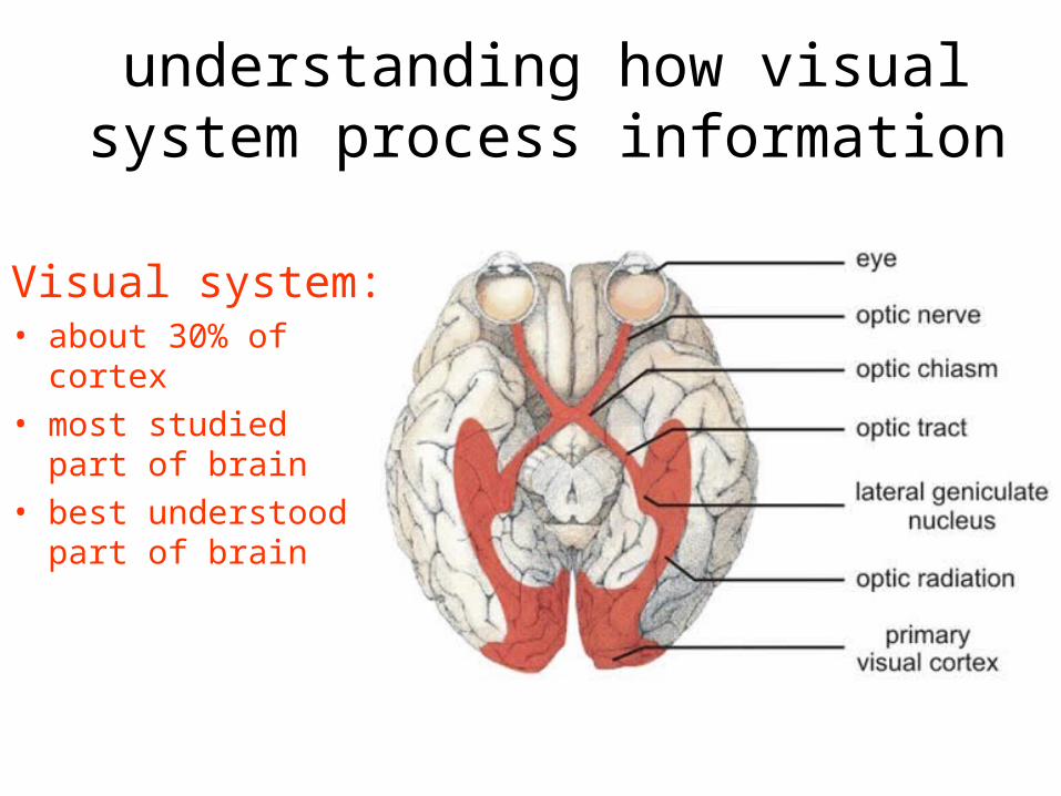
understanding how visual system process information
Visual system: • about 30% of cortex• most studied part of
brain• best understood part
of brain

Image sensors Binary sensor array
Luminance sensor array
Multi-Spectral sensor array

Where do we start?
We first need a model of what light information means.
Any visual system starts with a sensor:
What kind of information do these sensors produce?
Let’s first look at sensors we have designed!
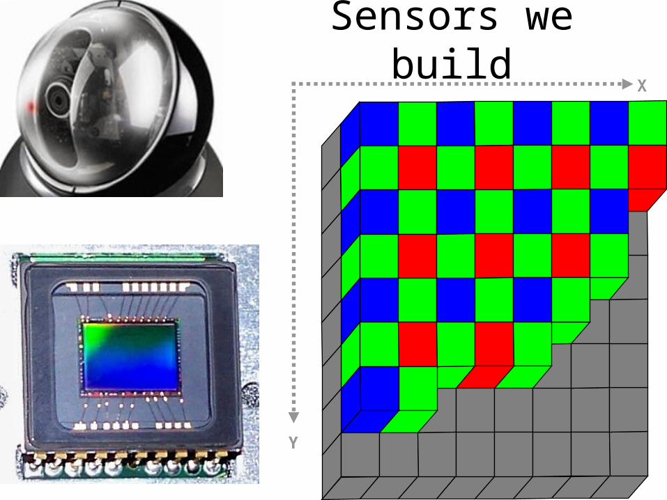
Sensors we buildX
Y

The Pixel
Sensors element may be:
Binary Luminance RGB
The fundamental unit of information!
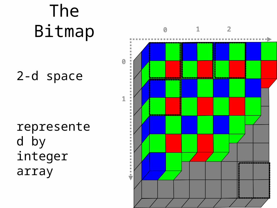
The Bitmap
2-d space
represented by integer array
0 1 2
0
1

What information is produced?
2-d array of pixels:
Black & White Pixel:– single luminance
value, usually 8 bit
Colour Pixel– 3 colour values,
usually 8-bit

Where we need to start: the fundamentals of the sensor
?
Human Visual
System (HVS)
The fundamentals!

The Sensor2 systems: day-sensor & night-sensor
To simplify: we ignore night sensor system
Cone Sensors very similar to RGB sensors we design for cameras

BUT: sensor array is not ordered
arrangement is random
note:very few blue sensors, none in the centre

sensor pre-processing circuitry

First Question: What information is sent from sensor array
to visual system?
Very clear division between sensor & pre-processing (Front of Brain) andvisual system (Back of Brain) connected with very limited communication link

Receptive Fields
All sensors in the retina are organized into receptive fields
Two types of receptive field.
Why?

What does a receptive field look like?
In the central fovea it is simply a pair of sensors.
Always 2 types:
• plus-centre
• minus-centre

What do retinal receptive fields do?
Produce an opponent value:simply the difference between 2 sensors
This means:
it is a relative measure, not an absolute measure
and
no difference = no information to brain
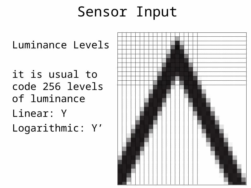
Sensor Input
Luminance Levels
it is usual to code 256 levels of luminance
Linear: Y
Logarithmic: Y’
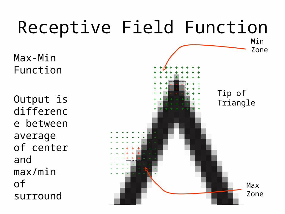
Receptive Field Function
- - -- - -- - -
+ + ++ + ++ + +
- - -- - -- - -
- - -- - -- - -
- - -- - -- - -
- - -- - -- - -
- - -- - -- - -
- - -- - -- - -
- - -- - -- - -
+ + ++ + ++ + +
- - -- - -- - -
+ + ++ + ++ + +
+ + ++ + ++ + +
+ + ++ + ++ + +
+ + ++ + ++ + +
+ + ++ + ++ + +
+ + ++ + ++ + +
+ + ++ + ++ + +
Min Zone
Max-Min Function
Output is difference between average of center and max/min of surround Max
Zone
Tip of Triangle

Dual Response to gradients
Why?
Often described assecond derivative/zero crossing
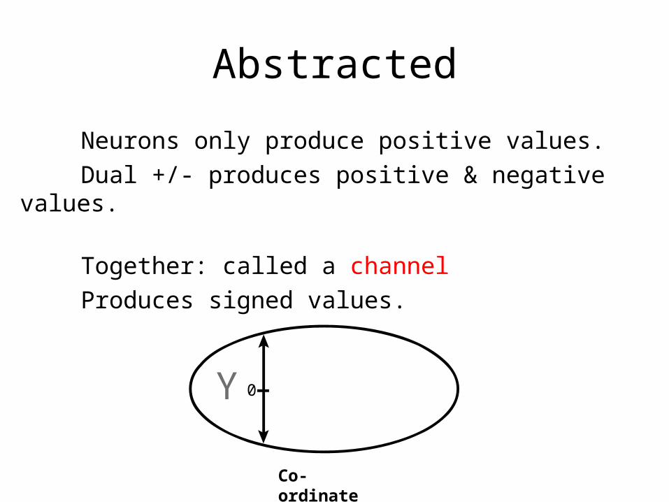
Abstracted
Neurons only produce positive values.
Dual +/- produces positive & negative values.
Together: called a channel
Produces signed values.
Co-ordinate
Y 0

Human Sensor Responseto monochromatic light stimuli
350 400 450 500 550 600 650 7000
10
20
30
40
50
60
70
80
90
100
Wavelength (nm)
Abso
rpti
on
(%
)
RGB

HVS Luminance Sensor IdealizedSe
nsor
Val
ue
Wavelength(λ)λ
0.8
0.6
0.2
0.0
1.0
0.4
λ+δλ−
A linear response in relation to wavelength.Under ideal conditions can be used to measure wavelength.

Spatially Opponent
HVS:Luminance is always measured by taking the difference between two sensor values.Produces: contrast value
Sens
or V
alue
Wavelength(λ)λ
0.8
0.6
0.2
0.0
1.0
0.4
λ+δλ−
Sens
or V
alue
Wavelength(λ)λ
0.8
0.6
0.2
0.0
1.0
0.4
λ+δλ−
Which is done twice, to get a signed contrast value

Moving from Luminance to Colour
• Primitive visual systems were in b&w• Night-vision remains b&w
• Evolutionary Path– Monochromacy– Dichromacy (most mammals – eg. the
dog)– Trichromacy (birds, apes, some monkeys)
• Vital for evolution: backwards compatibility

Electro-Magnetic Spectrum
Visible Spectrum
Visual system must represent light stimuli within this zone.
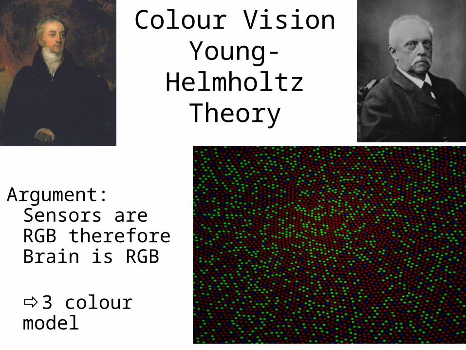
Colour Vision Young-Helmholtz
Theory
Argument:Sensors are RGB thereforeBrain is RGB
3 colour model

Hering colour opponency model
Fact: we never see reddish green or yellowish blue.
Therefore:colours must be arranged in opponent pairs:
RedGreenBlueYellow
4 colour model

HVS Colour Sensorsresponse to monochromatic light
350 400 450 500 550 600 650 7000
10
20
30
40
50
60
70
80
90
100
Wavelength (nm)
Abso
rpti
on
(%
)
RGB

How to calculate spectral frequency with 2 luminance sensors.
Sen
sor
Valu
e
Wavelength
0.8
0.6
0.2
0.0
1.0
0.4
λ-δ λ λ+δ
RG
Roughly speaking:

the ideal light stimulusS
en
sor
Valu
e
Wavelength
0.8
0.6
0.2
0.0
1.0
0.4
λ-δ λ λ+δ
RGMonochromatic Light
Allows frequency to be measured in relation to reference.

Problem:natural light is not ideal
Sen
sor
Valu
e
Wavelength
0.8
0.6
0.2
0.0
1.0
0.4
λ-δ λ λ+δ
RG
• Light stimulus might not activate reference sensor fully.
• Light stimulus might not be fully monochromatic.
ie. there might be white mixed in

Sens
or V
alue
Wavelength(λ, in nm)
400300 430 460 490 520 550 580 610 640 670 700
0.8
0.6
0.2
0.0
1.0
0.4
Solution:
A 3rd sensor is used to measure equiluminance.
Which is subtracted.
Then reference sensor can be normalized
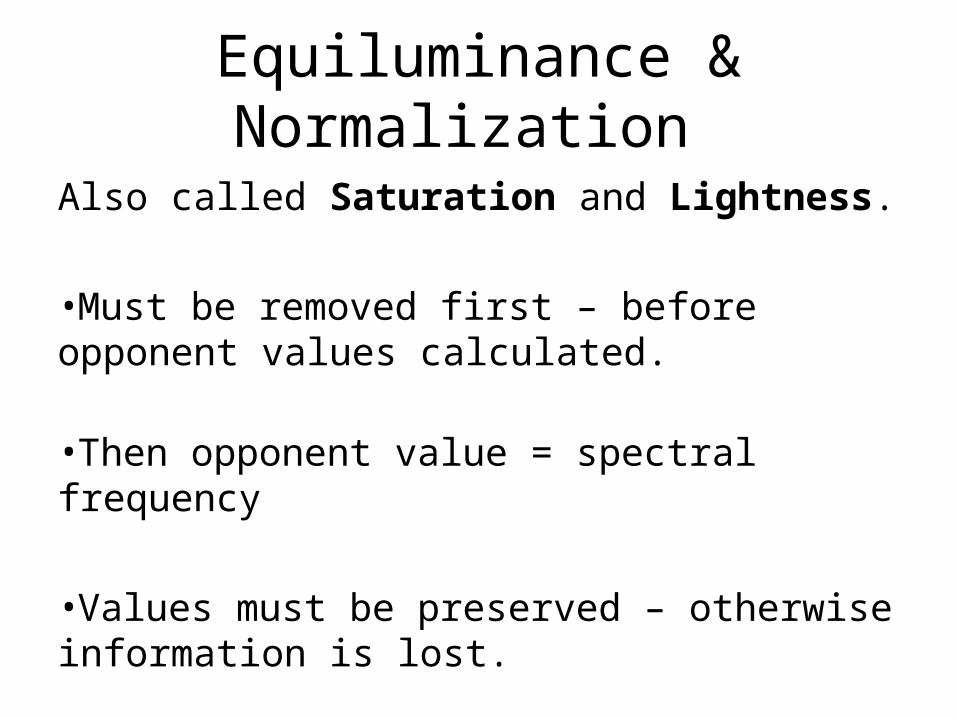
Equiluminance & Normalization
Also called Saturation and Lightness.
•Must be removed first – before opponent values calculated.
•Then opponent value = spectral frequency
•Values must be preserved – otherwise information is lost.

a 4 sensor designS
en
sor
Valu
e
Wavelength(λ, in nm)
400300 430 460 490 520 550 580 610 640 670 700
0.8
0.6
0.2
0.0
1.0
0.4
2 opponent pairs•only 1 of each pair can be active•min sensor is equiluminance
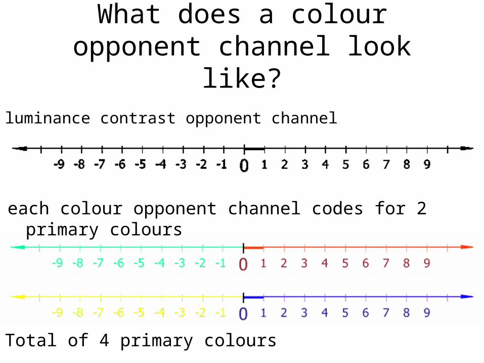
What does a colour opponent channel look like?
luminance contrast opponent channel
each colour opponent channel codes for 2 primary colours
Total of 4 primary colours

What is Colour?Colour is calculated exactly the same as luminance contrast. The only difference is spectral range of sensors is modified.Colour channels are: RGBY
Uncorrected colour values are contrast values.But with white subtracted and normalized:Colour is Wavelength!
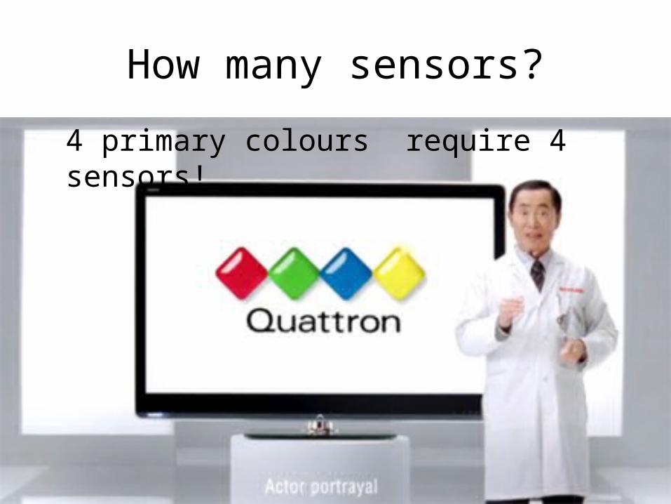
How many sensors?
4 primary colours require 4 sensors!

Human Retina only has 3 sensors!What to do?
Because of opponency when R=G, RG colour channel is 0.
Why not pair RG and reuse it as a Yellow sensor!
Yellow can be R=G

How do we abstract information from sensor array?
Luma (Y’)Red-Green (CB)Blue-Yellow (CR)

Luminance + 2 colour values+ 2 sensor correction values
Chroma BlueChroma Red
YC
C 0
B
R
0 + Lightness + Saturation

400 500 600 700 8000
1000
2000
3000
4000
Intensity(Counts)
Wavelength (nanomet res)
1
2
4
512
6
7
8 9
10
11 13 14
15 1617 18
1920 21 22
3
Tri-Phosphor Lightingoptimised for perception of ‘white’
ROYGBV380
450
495
570
590
620
750

Primary Colours matched to spectrum
ROYGBV380
450
495
570
590
620
750
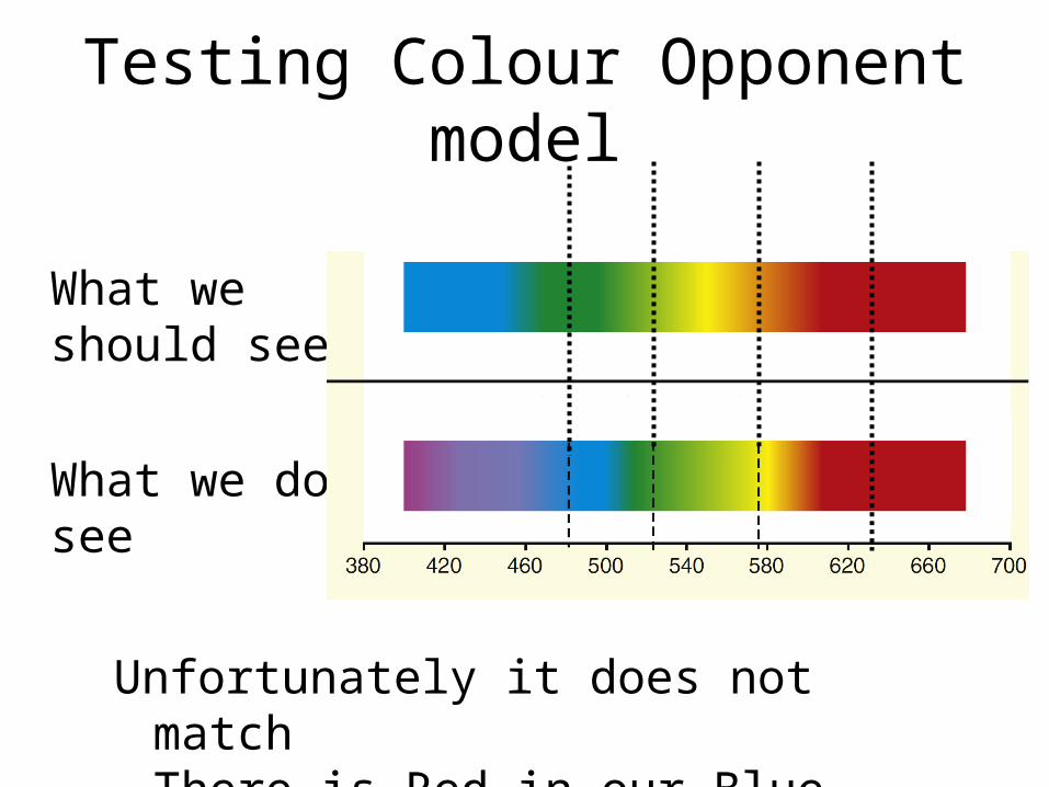
Testing Colour Opponent model
What we should see
What we do see
Unfortunately it does not matchThere is Red in our Blue

The strange case of Ultra-VioletLight with frequency of 400nm is ultra-blue
Red sensor is at opposite of spectrum & not stimulated.
Yet we see ultra-violet – which is Blue + Red
…and the more we go into UV the more red

Colour Matching Data (CIE 1931)(indirect sensor response)
a very odd fact – a virtual sensor
response

350 400 450 500 550 600 650 7000
10
20
30
40
50
60
70
80
90
100
Wavelength (nm)
Abso
rpti
on
(%
)RGB
Pigment Absorption Data of human cone sensors
350 400 450 500 550 600 650 7000
10
20
30
40
50
60
70
80
90
100
Wavelength (nm)
Abso
rpti
on
(%
)
RGB
Red > Green

Therefore:HVS colour representation must be circular!
Which is not a new idea, but not currently in fashion.
540nm
620nm
480nm

Dual Opponency with Circularity
an ideal model using 2 sensor pairs
Senso
r V
alu
e
Wavelength(λ, in nm)400300 430 460 490 520 550 580 610 640 670 700
0.8
0.6
0.2
0.0
1.0
0.4

Colour Wheel
Goethe & Munsell
Colours are represented by a single value: Hue

RYB Colour Circle
no longer used
Yellow-orange
Yellow-green
Red-orange
Red-violet
Blue-violet
Blue-green
Red
Green
Violet
Blue
Orange
Yellow
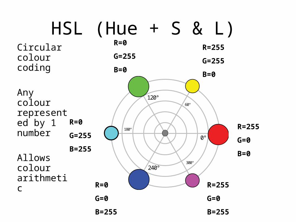
HSL (Hue + S & L)Circular colour coding
Any colour represented by 1 number
Allows colour arithmetic
240°
0°
120°60°
180°
300°
R=255
G=0
B=0
R=255
G=255
B=0
R=0
G=255
B=0
R=0
G=255
B=255
R=0
G=0
B=255
R=255
G=0
B=255

HSL & HSV
• Simple & Elegant
• But it is flawed:– simple transformation of RGB– colours do not match perception
• Why?
Because there are 4 primary colours, not 3!

gives us a 2-d colour space
CB
CR
Colour Information: 2 independent values

2-d space:
• Cartesian coordinates
or
• polar coordinates
Co-ordinate systems
BR CCr + arctan B
R
CC
(0,0)
(2,3)
CR
CB
0 1 L
θ
r
(3.6, 56.3º)

… requires 2 independent channels which give 4 primary colours
Yellow added as a primary!
Which allows a simple transform to circular representation
180°0°
90°
45°
135°
315°
270°
225°

Opponent Values HueA simple transform from 2 opponent values to a single hue value
How might HVS do this?we keep 2 colour channels but link them
180°0°
90°
45°
135°
315°
270°
225°
0
+64
+127
R = 255 G = 0 B = 128
Y - +
Ψ B
CG R
180°0°
90°
45°
135°
315°
270°
225°
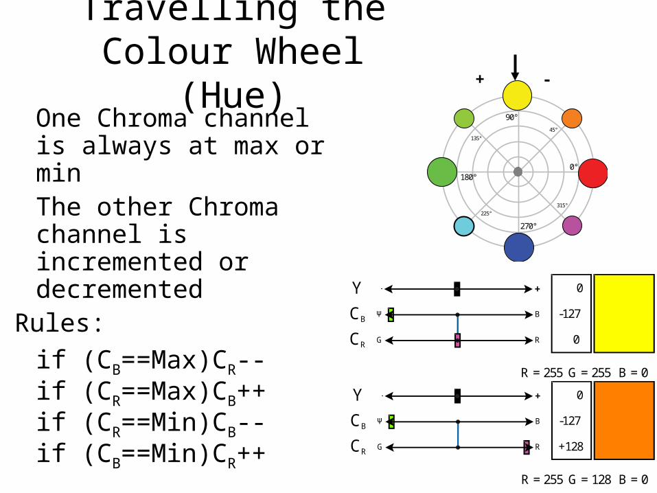
Travelling the Colour Wheel (Hue)
One Chroma channel is always at max or minThe other Chroma channel is incremented or decremented
Rules:
if (CB==Max)CR--if (CR==Max)CB++if (CR==Min)CB--if (CB==Min)CR++
180°0°
90°
45°
135°
315°
270°
225°
0
-127
+128
R = 255 G = 128 B = 0
Y - +
CBΨ B
CRG R
0
-127
0
R = 255 G = 255 B = 0
Y - +
CBΨ B
CRG R
+ -

Colour Wheel
Simple rule based system that cycles through the colour wheelAllows arithmetic operations on colour
180°0°
90°
45°
135°
315°
270°
225°
0
0
+127
R = 255 G = 0 B = 0
Y - +
CBΨ B
CRG R
0
+64
+127
R = 255 G = 0 B = 128
Y - +
CBΨ B
CRG R
0
+127
+127
R = 255 G = 0 B = 255
Y - +
CBΨ B
CRG R
0
+127
+64
R = 128 G = 0 B = 255
Y - +
CBΨ B
CRG R
0
+127
0
R = 0 G = 0 B = 255
Y - +
CBΨ B
CRG R
0
+127
-64
R = 0 G = 128 B = 255
Y - +
CBΨ B
CRG R
0
+127
-127
R = 0 G = 255 B = 255
Y - +
CBΨ B
CRG R
0
+127
-127
R = 0 G = 255 B = 0
Y - +
CBΨ B
CRG R
0
+127
-127
R = 128 G = 255 B = 0
Y - +
CBΨ B
CRG R
0
-127
0
R = 255 G = 255 B = 0
Y - +
CBΨ B
CRG R
0
-127
+128
R = 255 G = 128 B = 0
Y - +
CBΨ B
CRG R
0
-64
+127
R = 255 G = 128 B = 0
Y - +
CBΨ B
CRG R
0
0
+127
R = 255 G = 0 B = 0
Y - +
CBΨ B
CRG R

What is Hue?
Circular representation of spectrum
Its purpose is to provide a Spectrum Value
Primary Colours are the extreme ends of the 2 linked colour channels
0
0
+127
R = 255 G = 0 B = 0
Y - +
CBΨ B
CRG R
0
0
-128
R = 0 G = 255 B = 0
Y - +
CBΨ B
CRG R
0
+127
0
R = 0 G = 0 B = 255
Y - +
CBΨ B
CRG R
0
-128
0
R = 255 G = 255 B = 0
Y - +
CBΨ B
CRG R
180°0°
90°
45°
135°
315°
270°
225°

Hue: 2 values or 12 linked values allow us to turn colour off.
(0,0) is not an allowed hue, used for no colour
Simple standard input pixel:– luminance value or – colour value
64
0
0
R = 128 G = 128 B = 128
Y - +
CBΨ B
CRG R

Why do we need arithmetic on colour?
Colours are computed, not measured!

Colour is very useful for transparency
What is the colour?

Why do we need transparency?
otherwise we might have trouble with windows

… and difficulties with these kinds of tasks

Colour is very helpful in deciphering the layers
Aim: to reconstruct scenes with transparency

Y
X
It all must start with the right kind of sensor:
Format of ‘pixel’ as it enters visual area of brain for processing:
Y 0 YC
0
0
Luminance Information
Optional Colour Information
• Where on spectrum
• How colourful

visual systems with 4 sensors
• Birds• Reptiles• Dinosaurs• Therapsids (our
dinosaur-like ancestor)
about 60nm between sensors
evenly spaced frequencies narrowed
370 nm 445 nm 508 nm 565 nm
700 nm330 nm 400 nm 500 nm 600 nm
1.0
0.5
0.0

The Ideal Sensor
• Equally spaced on spectrum
• Overlap with linear transition
0.8
0.6
0.2
0.0
−5 −3 1 3 5
1.0
−1 0 2 4−2−4
y
0.8
0.6
0.2
0.0400 460 580 640
1.0
520 550 610 670490430
λ
0.4
0.8
0.6
0.2
0.0400 460 580 640
1.0
520 550 610 670490430
λ
0.4
0.8
0.6
0.2
0.0400 460 580 640
1.0
520 550 610 670490430
λ
0.4
colour channel 1: R - Gcolour channel 2: yellow - B
• No overlap of opponent pairs
spectrum is shifted toward more even spacing
445
555600
020406080100380 420 460 500 540 580 620 660 700
LMS
Absorption
424 530 560
Actual Sensor Response
Sensor Response calculated from CIE perceptual data
460 530 640
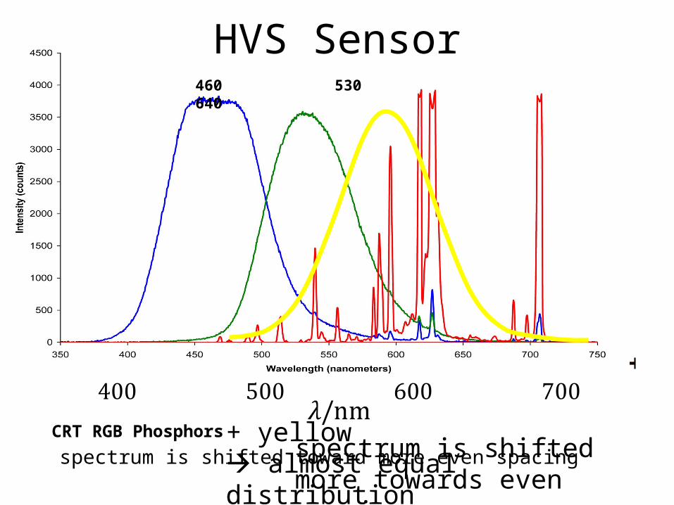
CRT RGB Phosphorsspectrum is shifted more towards even spacing
HVS Sensor
+ yellow almost equal distribution

a yellow sensor + a few tweaksmakes human vision equivalent to bird vision
• even spacing• 60nm between
primary colours• response
narrowed• intermediary
colours at half-way points
0.8
0.6
0.2
0.0
1.0
y
0.4
400 460 580 640520 550 610 670490430
λrequires more processing, is less accurate, but is equivalent

How do we get a yellow sensor?
we re-use red & green sensors
0.8
0.6
0.2
0.0
1.0
y
0.4
400 460 580 640520 550 610 670490430
&
but only when they are equal (R==G)This implies dividing by a measure of equality
( )
f
R Gy
E
+

Existing Circular Colour Systems:Munsell
colour wheel with
5 primary colours
100 years old
quite close

Existing Circular Colour Systems:CIE L*a*b* & CIE L*C*h
L*a*b* is a colour opponent space
L*C*h is the transform to circular
4 primary coloursRed = 0°Yellow = 90 °Green = 180 °Blue = 270 °

Summary
• Colour is based on contrast• HVS has a circular model of spectrum• Colour is a code for where on spectrum• 2 colour channels, bi-polar 4 primary
colours• 2 channels 2-d colour space• Simple transform to circular representation• Single variable represents all colours• Purpose is to allow systematic colour
transforms colour computation

References
Poynton, C. A. (1995). “Poynton’s Color FAQ”, electronic preprint.http://www.poynton.com/notes/colour_and_gamma/ColorFAQ.html
Bangert, Thomas (2008). “TriangleVision: A Toy Visual System”, ICANN 2008.
Goldsmith, Timothy H. (July 2006). “What birds see”. Scientific American: 69–75.
Neitz, Jay; Neitz, Maureen. (August 2008). “Colour Vision: The Wonder of Hue”. Current Biology 18(16): R700-r702.
Questions?

The problem with Yellow
Colour:an algorithmic
approach
Thomas Bangert
Thomas Bangert
MSc in Computer Sciency by Research.
Project Viva

Colour channels are pureOpponency means colour pairs are pure with respect to themselves.
It follows that a pure colour is achieved only when the other opponent channel is 0.
Reddest red only when B-RG is 0
Bluest blue only when R-G is 0and inversely

RGB is pureRed is reddest when G & B = 0 etc.
XYZ and LMS are not pure.
Sensors of visual system have a broad spectral response. They do not have a pure colour response.
Retinal processing produces pure colour channels from noisy and ambiguous data.
RGBRed: R=255, G=0, B=0Green: R=0, G=255, B=0Blue: R=0, G=0, B=255

YUV & YCBCR
Transforms
JPEG 2000 allows reversible simplification
Transform usually expressed in matrix form
JPEGwithout anything odd like ‘headroom’note: no negative numbers for JPEG, C+=128
(0.299 ) (0.587 ) (0.114 )
(0.168736 ) (0.331264 ) (0.5 )
(0.5 ) (0.418688 ) (0.081312 )B
R
Y R G B
C R G B
C R G B
+ + + + +
2; ; ;
4r b r
R G BY C B G C R G
+ +
0.299 0.587 0.114
0.147141 0.288869 0.43601
0.614975 0.514965 0.100010
Y R
U G
V B

Lets try some JPEG numbers:
not trivial ‘leakage’
0
255
0
150
84
107R
B
R
G
B
Y
C
C
255
0
0
76
43
127R
B
R
G
B
Y
C
C
0
255
255
179
43
128R
B
R
G
B
Y
C
C
0
0
255
29
127
21R
B
R
G
B
Y
C
C
Should be 127
Cyan

The Problem:
Colours channels are not pure.
They should be!
Y 0 Y
CBR=G B
CR
200
- 40
+ 60G R
R = 80 G = 60
R255 0 0
G02550
B 0 0255
Magenta
111127127
Cyan
195 127-128
RG255255 0
Cyan
0255255

YUV/YCRCB simplifiedA large number of transforms exist, most variations of YUV.
Minor tweaks of transform from XYZ can lead to quite large differences.
All of which work fine perceptually (meaning neurons are not that precise).
Why not simplify?
1 2
3 3Y R G +
1
2( )BC B Y
1
2( )RC R G
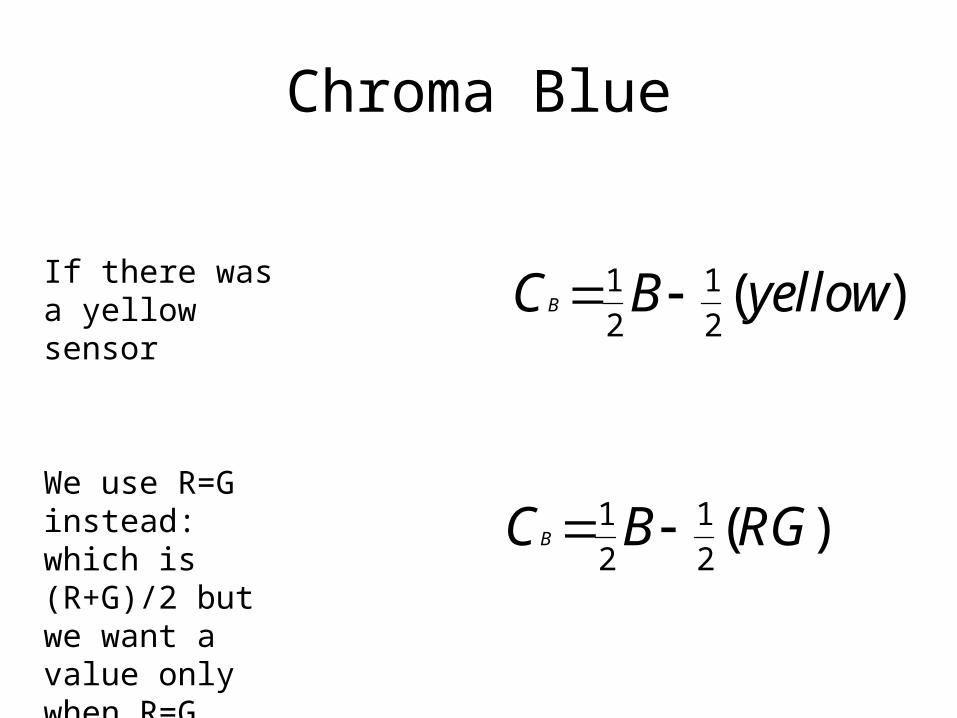
Chroma Blue
1 1
2 2( )BC B yellow If there was a
yellow sensor
We use R=G instead: which is (R+G)/2 but we want a value only when R=G
1 1
2 2( )BC B RG

Yellow: the Chroma Blue correction factor
The less equal R and G are, the less yellow there should be.
So:
Simply divide R by G to determine how close they are. The more equal they are the more active the ‘yellow’ sensor is.
1
2( )B BcfC B Y C
1
5( 0)B Bif C Y Y C +
1 2
3 3Y R G +
1
2( )RC R G
BcfRC G

Transform back to RGB
Fully Reversible
Calculate R and G first, then Blue correction factor.
4
3RR Y C +
2
3RG Y C
1
5( 0)B Bif C Y Y C
BcfRC G
2Bcf BB Y C C +

Samples of simple colour
transforms

Blue-Yellow set to 0

Red-Green inverted

Blue-Yellow
inverted
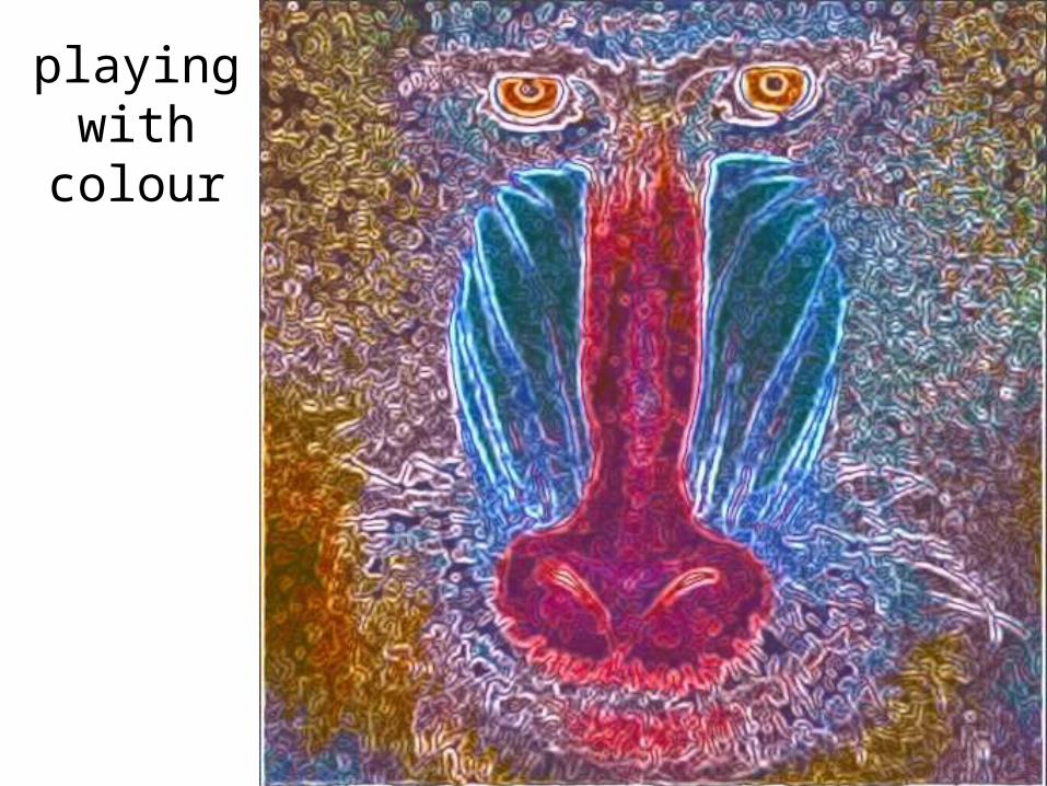
playing with colour

is easy

these are simple
transforms

not touched by
hand

YUV Summary
• Two simple tweaks allow us to correct conversion between RGB and YUV/YCRCB.
• Also allows conversion to be simplified.
1
5( 0)B Bif C Y Y C Bcf
RC G


