CIS 81 Fundamentals of NetworkingChapter 4: Network Access
Rick Graziani
Cabrillo College
Fall 2013

Chapter 4
4.1 Physical Layer Protocols 4.2 Network Media 4.3 Data Link Layer Protocols 4.4 Media Access Control 4.5 Summary

Comparing the two models
At the network access layer, the TCP/IP protocol suite does not specify which protocols to use when transmitting over a physical medium.
Only describes the handoff from the internet layer to the physical network protocols.
OSI Layers 1 and 2 discuss the necessary procedures to access the media and the physical means to send data over a network.
3

4
Focus on Data Link LayerIP
IP
Data Link Layer: Post-It Label on IP “box” (demo)Physical Layer: Roll or toss tennis balls (demo)

5
DataHTTP Header
TCP Header
IP Header
Data Link Header
Data Link Trailer
IP PacketData Link Header
Data Link Trailer
IP PacketData Link Header
Data Link Trailer
IP PacketData Link Header
Data Link Trailer
IP PacketData Link Header
Data Link Trailer
IP PacketData Link Header
Data Link Trailer
IP PacketData Link Header
Data Link Trailer
DataHTTP Header
TCP Header
IP Header
Data Link Header
Data Link Trailer
Reminder of encapsulation/decapsulation

Getting it Connected
Connecting to the Network
A physical connection can be a wired connection using a cable or a wireless connection using radio waves.

Getting it Connected
Connecting to the Network
Switches and wireless access points are often two separate dedicated devices, connected to a router.
Many homes use integrated service routers (ISRs),
Getting it Connected
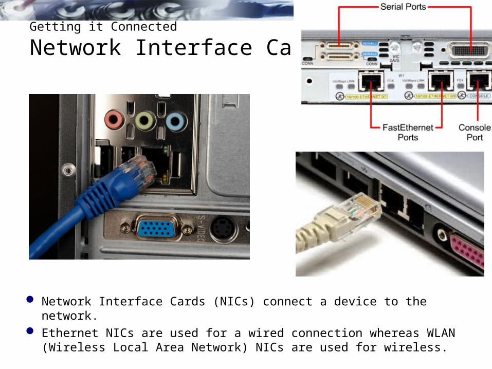
Network Interface Cards
Network Interface Cards (NICs) connect a device to the network. Ethernet NICs are used for a wired connection whereas WLAN
(Wireless Local Area Network) NICs are used for wireless.

Getting it Connected
Network Interface Cards
Connecting to the Wireless LAN with a Range Extender
Wireless devices must share access to the airwaves connecting to the wireless access point. Slower network performance may occur
A wired device does not need to share its access Each wired device has a separate communications channel over
its own Ethernet cable.

The Physical Layer
The OSI physical layer provides the means to transport the bits that make up a data link layer frame across the network media.

Purpose of the Physical Layer
Physical Layer Media
The physical layer produces the representation and groupings of bits for each type of media as:
Copper cable: The signals are patterns of electrical pulses. Fiber-optic cable: The signals are patterns of light. Wireless: The signals are patterns of microwave transmissions.

Purpose of the Physical Layer
Physical Layer Standards
Upper OSI layers are performed in software designed by software engineers and computer scientists.
TCP/IP suite are defined by the Internet Engineering Task Force (IETF) in RFCs

Purpose of the Physical Layer
Physical Layer Standards
Standard organization
Networking Standards
ISO• ISO 8877: Officially adopted the RJ connectors (e.g., RJ-11, RJ-45)• ISO 11801: Network cabling standard similar to EIA/TIA 568.
EIA/TIA
• TIA-568-C: Telecommunications cabling standards, used by nearly all voice, video and data networks.
• TIA-569-B: Commercial Building Standards for Telecommunications Pathways and Spaces
• TIA-598-C: Fiber optic color coding• TIA-942: Telecommunications Infrastructure Standard for Data Centers
ANSI • 568-C: RJ-45 pinouts. Co-developed with EIA/TIA
ITU-T • G.992: ADSL
IEEE• 802.3: Ethernet• 802.11: Wireless LAN (WLAN) & Mesh (Wi-Fi certification)• 802.15: Bluetooth
Who maintaining physical layer standards? Different international and national organizations, regulatory government
organizations, and private companies

Fundamental Principles of Layer 1
Physical Layer Fundamental Principles
MediaPhysical Components
Frame Encoding Technique
Signalling Method
Copper cable
• UTP• Coaxial• Connectors• NICs• Ports• Interfaces
• Manchester Encoding• Non-Return to Zero (NRZ)
techniques• 4B/5B codes are used with
Multi-Level Transition Level 3 (MLT-3) signaling
• 8B/10B• PAM5
• Changes in the electromagnetic field
• Intensity of the electromagnetic field
• Phase of the electromagnetic wave
Fiber Optic cable
• Single-mode Fiber• Multimode Fiber• Connectors• NICs• Interfaces• Lasers and LEDs• Photoreceptors
• Pulses of light• Wavelength multiplexing using
different colors
• A pulse equals 1.• No pulse is 0.
Wireless media
• Access Points• NICs• Radio• Antennae
• DSSS (direct-sequence spread-spectrum)
• OFDM (orthogonal frequency division multiplexing)
• Radio waves

Fundamental Principles of Layer 1
Physical Layer Fundamental Principles
Encoding or line encoding - Method of converting a stream of data bits into a predefined "codes”.
Signaling - The physical layer must generate the electrical, optical, or wireless signals that represent the "1" and "0" on the media.

Fundamental Principles of Layer 1
Encoding and Signaling
http://www.flukenetworks.com/content/neal-allens-network-maintenance-and-troubleshooting-guide-revealed

Fundamental Principles of Layer 1
Bandwidth
Bandwidth is the capacity of a medium to carry data. Typically measured in kilobits per second (kb/s) or megabits per
second (Mb/s).

Fundamental Principles of Layer 1
Throughput
Throughput is the measure of the transfer of bits across the media over a given period of time.
Due to a number of factors, throughput usually does not match the specified bandwidth in physical layer implementations.
http://www.speedtest.net/ http://ipv6-test.com/speedtest/

Fundamental Principles of Layer 1
Types of Physical Media
Different types of interfaces and ports available on a 1941 router

Network Media
Copper Cabling

Copper Cabling
Characteristics of Copper Media
Signal attenuation - the longer the signal travels, the more it deteriorates - susceptible to interference
Crosstalk - a disturbance caused by the electric or magnetic fields of a signal on one wire to the signal in an adjacent wire.
1 2
34

Copper Cabling
Copper Media
Counter the negative effects of different types of interference some cables are wrapped in metallic shielding
Counter the negative effects of crosstalk, some cables have opposing circuit wire pairs twisted together which effectively cancels the crosstalk.

Copper Cabling
Unshielded Twisted-Pair (UTP) Cable
Read this section… good stuff!

Copper Cabling
Shielded Twisted-Pair (STP) Cable
Foil Shields
Braided or Foil Shield

Copper Cabling
Coaxial Cable
Copper Cabling
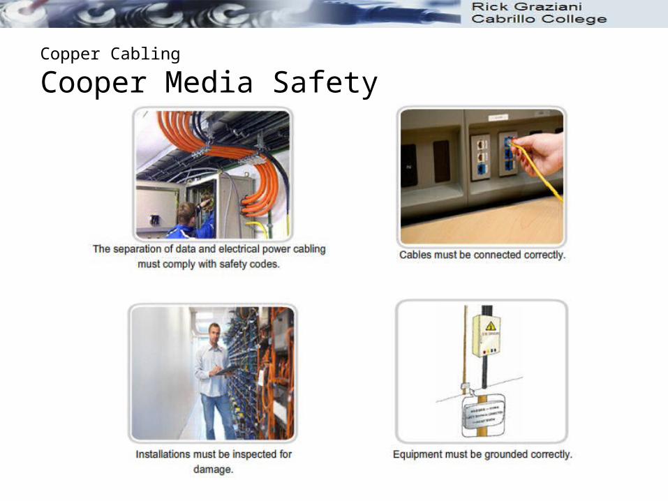
Cooper Media Safety

UTP Cabling
Properties of UTP Cabling
Read this section… more good stuff!

UTP Cabling
UTP Cabling Standards

UTP Cabling
UTP Connectors

UTP Cabling
Types of UTP Cable

UTP Cabling
Testing UTP Cables

Fiber Optic Cabling
Properties of Fiber Optic Cabling

Fiber Optic Cabling
Properties of Fiber Optic Cabling

Fiber Optic Cabling
Fiber Media Cable Design
Please read this section…. More good stuff!

Fiber Optic Cabling
Types of Fiber Media

Fiber Optic Cabling
Network Fiber Connectors

Fiber Optic Cabling
Testing Fiber Cables

Fiber Optic Cabling
Fiber versus CopperImplementation issues Copper media Fibre-optic
Bandwidth supported 10 Mbps – 10 Gbps 10 Mbps – 100 Gbps
DistanceRelatively short(1 – 100 meters)
Relatively High(1 – 100,000 meters)
Immunity to EMI and RFI LowHigh
(Completely immune)
Immunity to electrical hazards LowHigh
(Completely immune)
Media and connector costs Lowest Highest
Installation skills required Lowest Highest
Safety precautions Lowest Highest

Wireless Media
Properties of Wireless Media

• IEEE 802.11 standards• Commonly referred to as Wi-Fi.• Uses CSMA/CA• Variations include:
• 802.11a: 54 Mbps, 5 GHz• 802.11b: 11 Mbps, 2.4 GHz• 802.11g: 54 Mbps, 2.4 GHz• 802.11n: 600 Mbps, 2.4 and 5 GHz• 802.11ac: 1 Gbps, 5 GHz• 802.11ad: 7 Gbps, 2.4 GHz, 5 GHz, and 60 GHz
• IEEE 802.15 standard• Supports speeds up to 3 Mbps• Provides device pairing over distances from 1 to
100 meters.
• IEEE 802.16 standard• Provides speeds up to 1 Gbps• Uses a point-to-multipoint topology to provide
wireless broadband access.
Wireless Media
Types of Wireless Media

Wireless Media
802.11 Wi-Fi Standards
StandardMaximum
SpeedFrequency
Backwards compatible
802.11a 54 Mbps 5 GHz No
802.11b 11 Mbps 2.4 GHz No
802.11g 54 Mbps 2.4 GHz 802.11b
802.11n 600 Mbps 2.4 GHz or 5 GHz 802.11b/g
802.11ac 1.3 Gbps(1300 Mbps)
2.4 GHz and 5.5 GHz
802.11b/g/n
802.11ad 7 Gbps(7000 Mbps)
2.4 GHz, 5 GHz and 60 GHz
802.11b/g/n/ac

The Data Link Layer
The OSI physical layer provides the means to transport the bits that make up a data link layer frame across the network media.

Purpose of the Data Link Layer
The Data Link Layer
The data link layer is responsible for the exchange of frames between nodes over a physical network media.

Purpose of the Data Link Layer
Data Link SublayersNetwork
Data Link
LLC Sublayer
MAC Sublayer
Physical
Data Link layer has two sublayers (sometimes): Logical Link Control (LLC) – Software processes that provide services
to the Network layer protocols. Frame information that identifies the Network layer protocol. Multiple Layer 3 protocols, (ICMP, IPv4 and IPv6) can use the same
network interface and media. Media Access Control (MAC) - Media access processes performed by
the hardware. Provides Data Link layer addressing and framing of the data
according to the protocol in use.

Purpose of the Data Link Layer
Providing Access to Media
At each hop along the path, a router: Accepts a frame from a medium De-encapsulates the frame Re-encapsulates the packet into a
new frame Forwards the new frame
appropriate to the medium of that segment of the physical network

Data Link Layer
Layer 2 Frame Structure
The data link layer prepares a packet for transport across the local media by encapsulating it with a header and a trailer to create a frame.

Topologies
Controlling Access to the Media
48
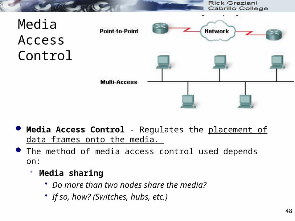
Media Access Control
Media Access Control - Regulates the placement of data frames onto the media.
The method of media access control used depends on: Media sharing
Do more than two nodes share the media? If so, how? (Switches, hubs, etc.)
49
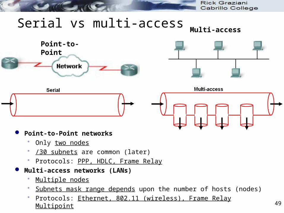
Serial vs multi-access
Point-to-Point networks Only two nodes /30 subnets are common (later) Protocols: PPP, HDLC, Frame Relay
Multi-access networks (LANs) Multiple nodes Subnets mask range depends upon the number of hosts (nodes) Protocols: Ethernet, 802.11 (wireless), Frame Relay Multipoint
Point-to-Point
Multi-access

Topologies
Physical and Logical Topologies

51
Physical Topology
The physical topology is an arrangement of the nodes and the physical connections between them.
Layer 2 Switch
Multilayer Switch
Serial Connections

52
Logical Topology
A logical topology - The way a network transfers frames from one node to the next. Defined by Data Link
layer protocols. Media Access
Control used. Type of network
framing

53
Point-to-Point topology
A point-to-point topology connects two nodes directly together. The media access control protocol can be very simple. Frames from one devices are for the device at the other end.
Point-to-point topologies, with just two interconnected nodes, do not require special addressing.
11111111

54
Logical Point-to-Point Networks
Point-to-point networks may include intermediate devices. No affect on logical topology. The logical connection (in some cases) may be a virtual circuit.
A virtual circuit is a logical connection created within a network between two network devices.
The two nodes exchange the frames with each other. Data Link Destination address is the device at the other end of
the virtual circuit.

55
Multi-access Topology
A logical multi-access topology - Enables a number of nodes to communicate by using the same shared media. “Data from only one node can be placed on the medium at any
one time.” (This is only true when using CSMA/CD (hubs), NOT true
with switches. Wireless uses CSMA/CA) Every node “may” see all the frames that are on the medium. Data Link Destination Address denote which device the frame is for.

56
Multi-access Addressing
Multi-access networks require an address to specifically identify the destination.
2222
3333
4444
5555
6666
22226666

LAN Topologies
Logical Topology for Shared Media

LAN Topologies
Contention-Based Access
Characteristics Contention-Based Technologies• Stations can transmit at any time• Collision exist• There are mechanisms to resolve
contention for the media
• CSMA/CD for 802.3 Ethernet networks• CSMA/CA for 802.11 wireless networks

59
Media Access Control
The media access control methods used by logical multi-access topologies are typically: CSMA/CD - Hubs CSMA/CA - Wireless Token passing – Token Ring
Later

WAN Topologies
Half and Full Duplex

61
Duplex Transmissions
Simplex Transmission: One way and one way only. One way street
Half-duplex Transmission: Either way, but only one way at a time. Two way street, but only one way at a time (land slide). Ethernet hubs use half-duplex
Full-duplex Transmission: Both ways at the same time. Two way street Ethernet switches use full-duplex Most serial links are full-duplex

62
Data Link Frame Fields
Data Link frame header fields may include: Start Frame field - Indicates the beginning of the frame Source and Destination address fields - Indicates the source
and destination nodes on the media Priority/Quality of Service field - Indicates a particular type of
communication service for processing Type field - Indicates the upper layer service contained in the
frame Logical connection control field - Used to establish a logical
connection between nodes Physical link control field - Used to establish the media link Flow control field - Used to start and stop traffic over the media Congestion control field - Indicates congestion in the media

63
Framing- The Trailer
The signals on the media could be subject to: Interference Distortion Loss
This would change the bit values that those signals represent.
The trailer is used to determine if the frame arrived without error. Error detection.
The Frame Check Sequence (FCS) field is used to determine if errors occurred in the transmission and reception of the frame.

64
Cyclic Redundancy Check
Cyclic redundancy check (CRC) is commonly used. Sending node includes a logical summary of the bits in the frame. Receiving node calculates its own logical summary, or CRC.
Compares the two CRC values. Equal – Accepts the frame Different – Discards the frame

65
Ethernet Protocol for LANs
Ethernet is a family of networking technologies that are defined in the IEEE 802.2 and 802.3 standards.
Uses 48 bit addressing (Ethernet MAC addresses) for Source and Destination
More next week!

66
Point-to-Point Protocol for WANs
Point-to-Point Protocol (PPP) is a protocol used to deliver frames between two nodes.
PPP can be used on various physical media, including: Twisted pair Fiber optic lines Satellite transmission

67
Wireless Protocol for LANs
802.11 is an extension of the IEEE 802 standards. It uses the same 48-bit addressing scheme as other 802 LANs. Contention-based system using a Carrier Sense Multiple
Access/Collision Avoidance (CSMA/CA)

CIS 81 Fundamentals of NetworkingChapter 4: Network Access
Rick Graziani
Cabrillo College
Fall 2013


