
1
Chapter 6 Applications
Office Hours:
BKD 3601-7
Tuesday 14:00-16:00
Thursday 9:30-11:30

2
Chapter 6 Applications
Office Hours:
BKD 3601-7
Tuesday 14:00-16:00
Thursday 9:30-11:30
6.1 3G (UMTS and WCDMA)
Cellular History
3
The first-generation (1G) mobile telecommunication systems introduced in the 1980s were analog.
The second-generation (2G) systems are digital and have data transport capabilities but only to a limited extent. GSM supports SMSs and user data at rates only up to 9.6 kb/s. Security features including (for example) the encryption of data and signaling
messages on the path between the mobile phone and the BS.
Subscriber identity module (SIM)
A smart card
Contain the subscriber‘s personal details
Can be moved from one handset to another.
IS-95B (cdmaOne) provides data rates in the range of 64 to 115 kb/s in increments of 8 kb/s over a 1.25 MHz channel. Each cell uses a carrier with a bandwidth of 1.25MHz, which is divided into
64 data and signalling channels by the use of orthogonal CDMA codes.

Review: GSM (2G)
4
[Karim and Sarraf, 2002, Fig 5-1]
[Karim and Sarraf, 2002, Fig 5-10]

2.5G: GSM Enhancement
5
Want to deliver data as well as voice.
General Packet Radio Service (GPRS)
Enhanced Data Rates for GSM Evolution (EDGE)
2.5G: GPRS
6
General Packet Radio Service
The first commercial launches for GPRS took place in 2001.
Provide connectivity to IP networks (Internet). Construction of a packet switched core network, to run alongside the circuit
switched network that was originally built for GSM.
A single time slot may be shared by multiple users for transferring packet mode data
Each slot can handle up to 20 kb/s. Each user may be allocated up to 8 slots Data rates up to about 160 kb/s per user are possible.
A good approximation for throughput in ―average‖ conditions is 10 Kbps per time slot. [Korhonen, 2003]
Especially suitable for non-real-time applications, such as e-mail and Web surfing.
Bursty data is well handled with GPRS, as it can adjust the assigned resources according to current needs.
Not well-suited for real-time applications Resource allocation in GPRS is contention based
Cannot guarantee an absolute maximum delay.

2.5G: EDGE
7
Enhanced Data Rates for GSM Evolution Originally this acronym stood for Enhanced Data rates for GSM Evolution,
but now it translates into Enhanced Data rates for Global Evolution, as the EDGE idea can also be used in systems other than GSM [Korhonen, 2003]
Support IP-based services in GSM at rates up to 384 kb/s
Higher modulation efficiency Eight-phase shift keying (8PSK) Can only be used effectively over a short distance.
For wide area coverage, the old GMSK (Gaussian minimum shift key) is still needed.
Only requires a software upgrade to base stations if the RF amplifiers can handle the non-constant envelope modulation with EDGE‘s relatively high peak-to-average power ratio (PAPR).
EDGE is popular in North America, where the allocation of carrier frequencies has made it hard for GSM operators to upgrade to UMTS.

Motivation
8
UMTS: History
9
The research activity on UMTS started in Europe at the beginning of the 1990s.
The third-generation mobile communication systems, called International Mobile Telecommunications-2000 (IMT-2000) or Universal Mobile Telecommunications System (UMTS) in Europe, are designed to support wideband services with data rates up to 2Mbit/s.
This system was developed from GSM Keep the core network more-or-less intact Change the air interface to use CDMA
There is some compatibility between the two systems: Most UMTS mobiles also implement GSM, and the network can hand them
over from a UMTS base station to a GSM one if they reach the edge of the UMTS coverage area.
However, network operators cannot implement the two systems in the same frequency band, so they are not fully compatible with each other.

Market Share
10
Numbers of subscribers to different mobile communication
technologies in 2008.
[Cox, 2008, Fig 1.15]
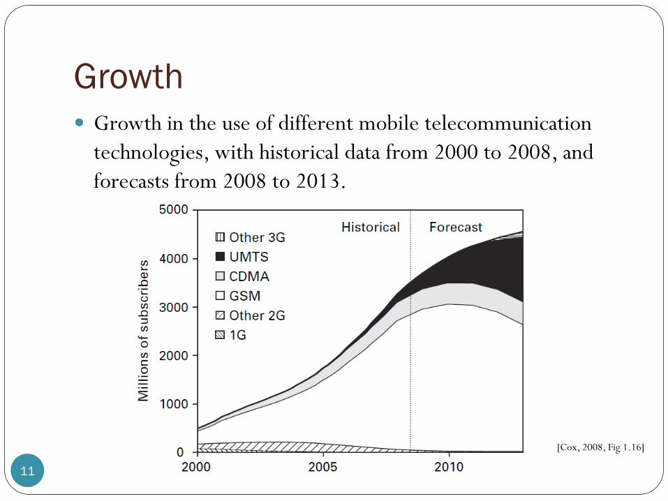
Growth
11
Growth in the use of different mobile telecommunication
technologies, with historical data from 2000 to 2008, and
forecasts from 2008 to 2013.
[Cox, 2008, Fig 1.16]

UMTS: FDD
12
Universal Mobile Telecommunications System (UMTS)
The chip rate for spectrum spreading is 3.84 Mc/s.
The maximum transmitter power of the user equipment is in
the range of 21 to 33 dBm (that is, 125 mW to 2 W)
[Karim and Sarraf, 2002, Fig 6-1]
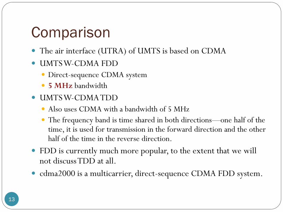
Comparison
13
The air interface (UTRA) of UMTS is based on CDMA
UMTS W-CDMA FDD
Direct-sequence CDMA system
5 MHz bandwidth
UMTS W-CDMA TDD
Also uses CDMA with a bandwidth of 5 MHz
The frequency band is time shared in both directions—one half of the time, it is used for transmission in the forward direction and the other half of the time in the reverse direction.
FDD is currently much more popular, to the extent that we will not discuss TDD at all.
cdma2000 is a multicarrier, direct-sequence CDMA FDD system.

Spreading Codes
14
In UMTS and cdma2000, signaling and user data is spread
twice in succession
First with the channelization codes
Orthogonal Walsh codes
Inherently more tolerant of interference caused by multiple users.
Later with the scrambling codes
Not necessarily orthogonal
Built from PN codes
In contrast to IS-95, the WCDMA/UMTS standard applies
variable length orthogonal spreading codes and coherent
QPSK detection for both uplink and downlink directions.
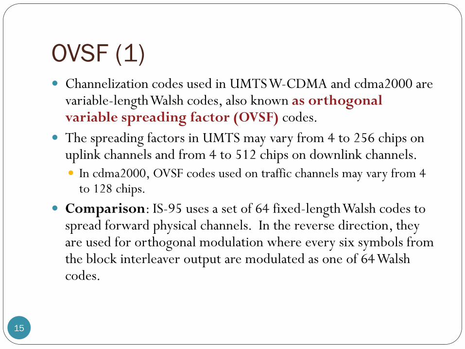
OVSF (1)
15
Channelization codes used in UMTS W-CDMA and cdma2000 are variable-length Walsh codes, also known as orthogonal variable spreading factor (OVSF) codes.
The spreading factors in UMTS may vary from 4 to 256 chips on uplink channels and from 4 to 512 chips on downlink channels.
In cdma2000, OVSF codes used on traffic channels may vary from 4 to 128 chips.
Comparison: IS-95 uses a set of 64 fixed-length Walsh codes to spread forward physical channels. In the reverse direction, they are used for orthogonal modulation where every six symbols from the block interleaver output are modulated as one of 64 Walsh codes.
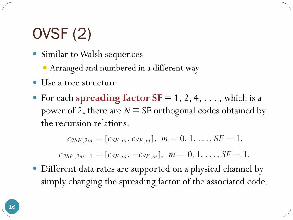
OVSF (2)
16
Similar to Walsh sequences
Arranged and numbered in a different way
Use a tree structure
For each spreading factor SF = 1, 2, 4, . . . , which is a
power of 2, there are N = SF orthogonal codes obtained by
the recursion relations:
Different data rates are supported on a physical channel by
simply changing the spreading factor of the associated code.

Tree structure for OVSF codes (1)
17
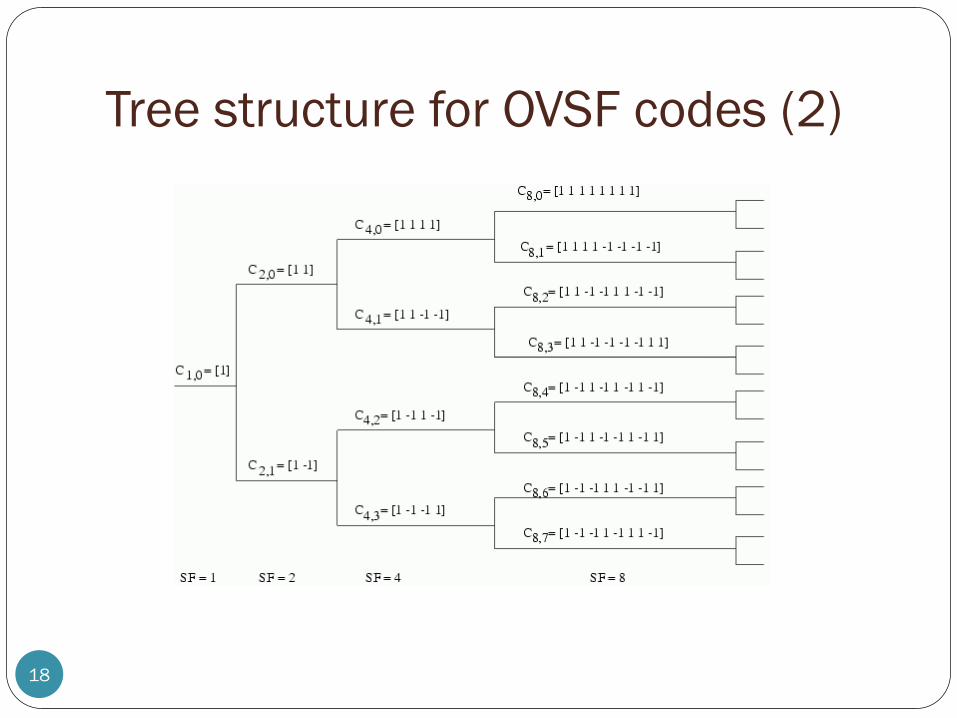
Tree structure for OVSF codes (2)
18

Code allocation rules (1)
19
OVSF codes can be applied to realize connections with
different data rates by varying the spreading factor.
Smaller SF = Faster data rate
To have connections with different data rates, need some
rules (for selecting the codes) to maintain orthogonality
Code blocking property: If a certain code is already used
for one connection, neither this code nor a code that is a
descendant or an ancestor of this code (on the tree) is
allowed to be used for another connection
These codes are not orthogonal to the already allocated one.

Code allocation rules (2)
20[Schulze Luders, 2005, Fig 5.12]
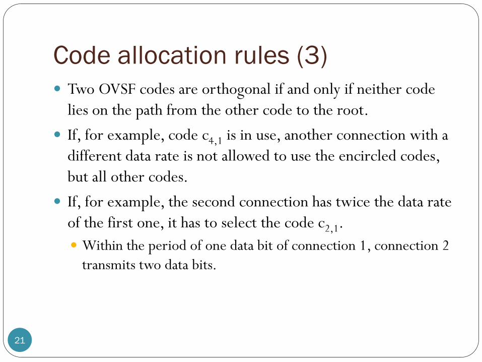
Code allocation rules (3)
21
Two OVSF codes are orthogonal if and only if neither code
lies on the path from the other code to the root.
If, for example, code c4,1 is in use, another connection with a
different data rate is not allowed to use the encircled codes,
but all other codes.
If, for example, the second connection has twice the data rate
of the first one, it has to select the code c2,1.
Within the period of one data bit of connection 1, connection 2
transmits two data bits.

OVSF: Disadvantages
22
Poor autocorrelation property
Look, for example, at the codes cSF,0.
When there is no perfect synchronization, the orthogonality
gets lost (high values for the cross correlation)

Scrambling Codes in UMTS
23
The scrambling codes in UMTS are complex valued and may be either long or short.
A long code has a length of 38,400 chips (that is, 10 ms) and a short code only 256 chips.
A long code for a UMTS uplink channel is constructed with two PN codes, whose characteristic polynomials are
They are implemented as sequences PN1 and PN2 using two 25-bit shift registers.
PN1 and PN2 are added modulo 2, and the output is mapped to a real-valued function, say, I.
Another function Q is derived by simply delaying I by 224 + 16 chips.
Q is multiplied by j, where the sign changes every chip period, and then added to I to yield the long code.
25 3 25 3 2
1 21 and 1g x x x g x x x x x

A long code generator for a UMTS
uplink channel
24 [Karim and Sarraf, 2002, Fig 3-19]
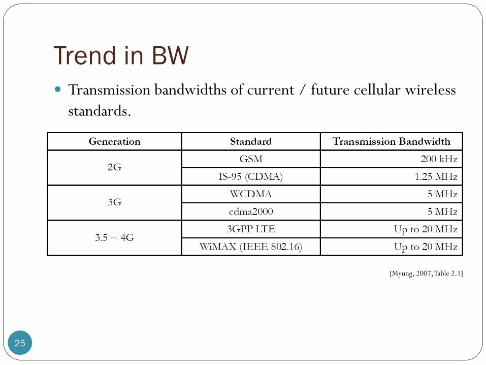
Trend in BW
25
Transmission bandwidths of current / future cellular wireless
standards.
[Myung, 2007, Table 2.1]

HSPA
26
High Speed Packet Access (HSPA) is a collection of two mobile telephony protocols
High Speed Downlink Packet Access (HSDPA) and
High Speed Uplink Packet Access (HSUPA)
Extend and improve the performance of existing WCDMA protocols.
Use improved modulation schemes and refine the protocols by which handsets and base stations communicate.
Many HSPA rollouts can be achieved by a software upgrade to existing 3G networks, giving HSPA a head start over WiMAX, which requires dedicated network infrastructure.
There is also a further standard, Evolved HSPA (HSPA+).
27
Chapter 6 Applications
Office Hours:
BKD 3601-7
Tuesday 14:00-16:00
Thursday 9:30-11:30
6.2 WiMAX
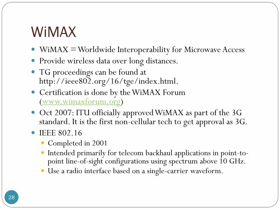
WiMAX
28
WiMAX = Worldwide Interoperability for Microwave Access
Provide wireless data over long distances.
TG proceedings can be found at http://ieee802.org/16/tge/index.html.
Certification is done by the WiMAX Forum (www.wimaxforum.org)
Oct 2007: ITU officially approved WiMAX as part of the 3G standard. It is the first non-cellular tech to get approval as 3G.
IEEE 802.16 Completed in 2001 Intended primarily for telecom backhaul applications in point-to-
point line-of-sight configurations using spectrum above 10 GHz. Use a radio interface based on a single-carrier waveform.

“Fixed” WiMAX
29
802.16-2004 based systems
Fixed broadband wireless MAN
Added multiple radio interfaces, including one based on OFDM-256 and one based on OFDMA.
Support point-to-multipoint communications, sub-10 GHz operation, and non-line-of-sight communications.
Potential applications include wireless Internet Service Provider (ISP) service, local telephony bypass, as an alternative to cable modem or DSL service, and for cellular backhaul for connections from cellular base stations to operator infrastructure networks.

“Mobile” WiMAX
30
Used to describe 802.16e-2005 based systems.
802.16e-2005 = 802.16-2004 standard + 802.16e amendment
Specify scalable OFDM for the physical layer and makes further modifications to the MAC layer to accommodate high-speed mobility
Adds mobility capabilitie including support for radio operation while mobile, handovers across base stations, and handovers across operators.
Not backward-compatible with IEEE 802.16-2004 networks
Employ many of the same mechanisms as HSPA to maximize throughput and spectral efficiency, including high-order modulation, efficient coding, adaptive modulation and coding, and Hybrid Automatic Repeat Request (HARQ).
The principal difference from HSDPA is the use of OFDMA.
OFDM systems exhibit greater orthogonality on the uplink, so IEEE 802.16e-2005 may have slightly greater uplink spectral efficiency than even HSUPA.
Trend
31
WiMAX has emerged as a potential alternative to cellular technology for wide-area wireless networks.
WiMAX is trying to challenge existing wireless technologies—promising greater capabilities and greater efficiencies than alternative approaches such as HSPA.
But as WiMAX, particularly mobile WiMAX, has come closer to reality, vendors have continued to enhance HSPA, and actual WiMAX advantages are no longer apparent.
Any potential advantages certainly do not justify replacing 3G systems with WiMAX.
Instead, WiMAX has gained the greatest traction in developing countries as an alternative to wireline deployment.

OFDMA
32
Orthogonal Frequency Division Multiple Access.
The multi-user version of OFDM
Dynamically assign subset of subcarriers to individual users for
intervals of time.
WiMAX is the first cellular standard that employs OFDMA.
Large number of sub-carriers (up to 211 = 2048).
Resource Allocation
33
Active (data and pilots) sub-carriers are grouped into subsets of subcarriers called subchannels.
Subchannels are further grouped into bursts which can be allocated to wireless users.
Each burst allocation can be changed from frame to frame.
This allows the BS to dynamically adjust the bandwidth usage according to the current system requirements.
Based on feedback about the channel conditions, the system can implement adaptive user-to-subcarrier assignment. As long as these subcarrier assignments are executed quickly, fast
fading and narrow-band co-channel interference performance is improved compared to OFDM.
This, in turn, improves system spectral efficiency.
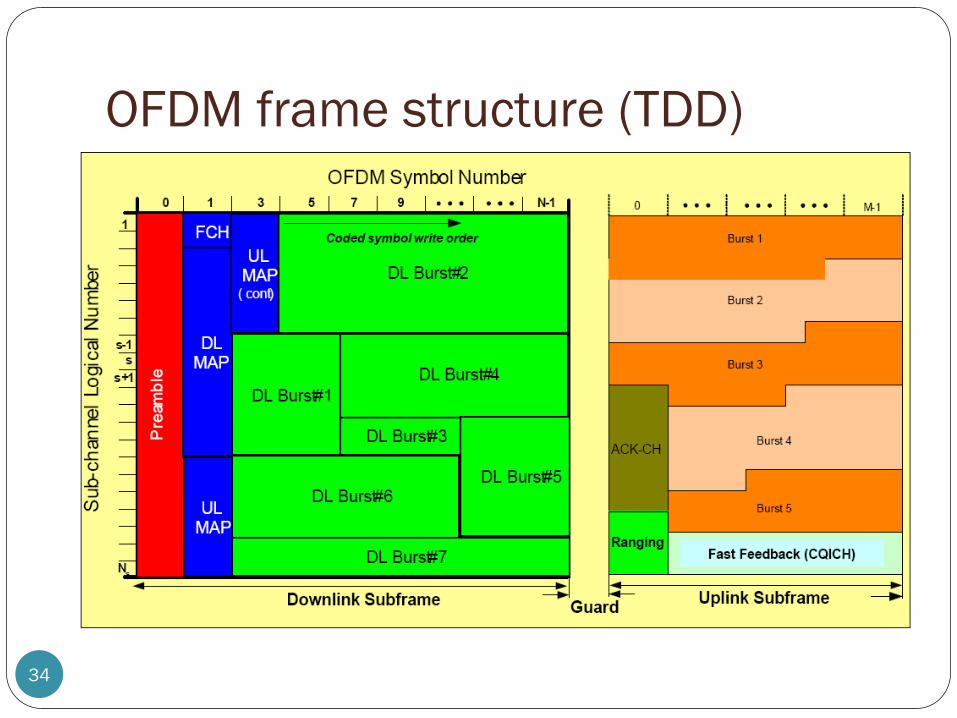
OFDM frame structure (TDD)
34
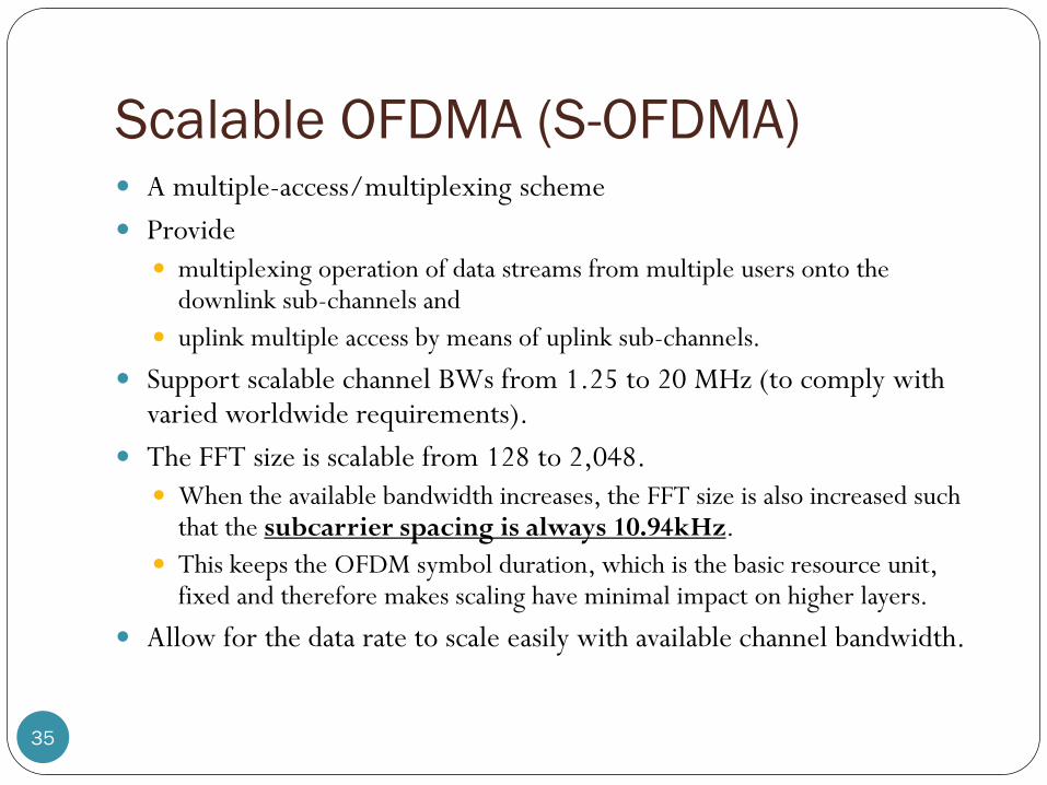
Scalable OFDMA (S-OFDMA)
35
A multiple-access/multiplexing scheme
Provide
multiplexing operation of data streams from multiple users onto the downlink sub-channels and
uplink multiple access by means of uplink sub-channels.
Support scalable channel BWs from 1.25 to 20 MHz (to comply with varied worldwide requirements).
The FFT size is scalable from 128 to 2,048.
When the available bandwidth increases, the FFT size is also increased such that the subcarrier spacing is always 10.94kHz.
This keeps the OFDM symbol duration, which is the basic resource unit, fixed and therefore makes scaling have minimal impact on higher layers.
Allow for the data rate to scale easily with available channel bandwidth.
36
Chapter 6 Applications
Office Hours:
BKD 3601-7
Tuesday 14:00-16:00
Thursday 9:30-11:30
6.3 4G (LTE for UMTS)

37
Chapter 6
Office Hours:
BKD 3601-7
Tuesday 14:00-16:00
Thursday 9:30-11:30
Applications: 4G (LTE for UMTS)

4G
38
Unlike the 3G networks, which use both circuit
switching and packet switching, 4G uses packet switching only.
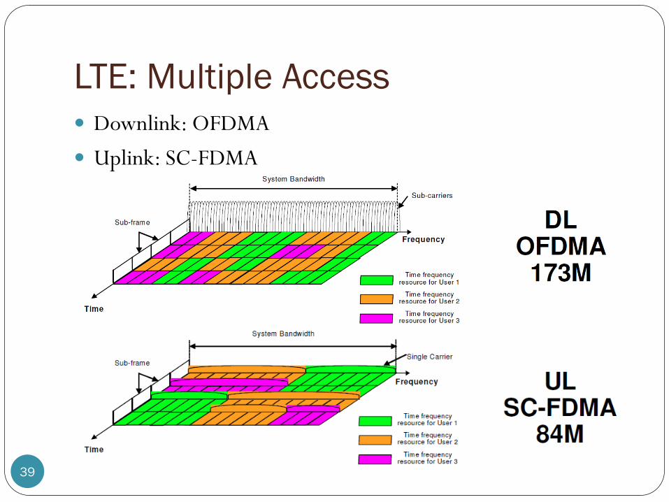
LTE: Multiple Access
39
Downlink: OFDMA
Uplink: SC-FDMA

LTE: OFDMA
40
15 kHz subcarrier spacing
Downlink Resource
Assignment in Time and
Frequency
[Rysavy, 2007, Fig 37]
[Holma and Toskala, 2009, Fig 4.4]
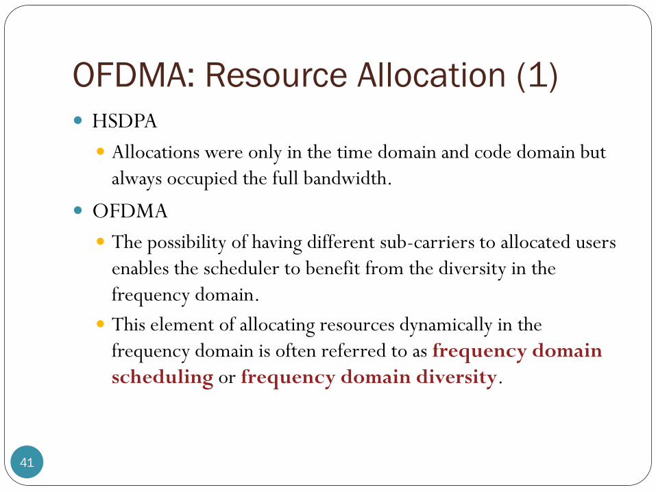
OFDMA: Resource Allocation (1)
41
HSDPA
Allocations were only in the time domain and code domain but
always occupied the full bandwidth.
OFDMA
The possibility of having different sub-carriers to allocated users
enables the scheduler to benefit from the diversity in the
frequency domain.
This element of allocating resources dynamically in the
frequency domain is often referred to as frequency domain
scheduling or frequency domain diversity.

OFDMA: Resource Allocation (2)
42
Allocation is not done on an individual sub-carrier basis but is based on resource blocks. It would be far too inefficient to try either to obtain feedback with 15 kHz
sub-carrier resolution or to signal the modulation applied on a individual sub-carrier basis.
Each resource block consisting of 12 sub-carriers, thus resulting in the minimum bandwidth allocation being 180 kHz.
When the respective allocation resolution in the time domain is 1 ms, the downlink transmission resource allocation thus means filling the resource pool with 180 kHz blocks at 1 ms resolution.
Note that the resource block in the specifications refers to the 0.5 ms slot, but the resource allocation is done anyway with the 1 ms resolution in the time domain.
[Holma and Toskala, 2009, Fig 4.10]

OFDMA: Channel Estimation
43
Have reference or pilot symbols.
With the proper placement of these symbols in both the time
and frequency domains, the receiver can interpolate the
effect of the channel to the different sub-carriers from this
time and frequency domain reference symbol ‗grid‘.
[Holma and Toskala, 2009, Fig 4.8]

OFDMA: Equalizer
44
Frequency domain equalizer basically reverts the channel
impact for each sub-carrier.
The frequency domain equalizer in OFDMA simply
multiplies each sub-carrier (with the complex-valued
multiplication) based on the estimated channel frequency
response (the phase and amplitude adjustment each sub-
carrier has experienced) of the channel.
This is clearly a simpler operation compared with WCDMA
and is not dependent on channel length (length of multipath
in chips) as is the WCDMA equalizer.

OFDMA Problem: PAPR
45
The OFDMA signal envelope varies strongly, compared to a
normal QAM modulator, which is only sending one symbol
at a time (in the time domain).
[Holma and Toskala, 2009, Fig 4.11]

OFDMA Problem: PAPR (2)
46
This causes some challenges to the amplifier design as, in a cellular system, one should aim for maximum power amplifier efficiency to achieve minimum power consumption.
A signal with a higher envelope variation (such as the OFDMA signal in the time domain) requires the amplifier to use additional back-off. The amplifier must stay in the linear area with the use of extra power back-off.
The use of additional back-off leads to a reduced amplifier power efficiency or a smaller output power.
This either causes the uplink range to be shorter or, when the same average output power level is maintained, the battery energy is consumed faster due to higher amplifier power consumption. The latter is not considered a problem in fixed applications where the device has a large
volume and is connected to the mains, but for small mobile devices running on their own batteries it creates more challenges.
This was the key reason why 3GPP decided to use OFDMA in the downlink direction but to use the power efficient SC-FDMA in the uplink direction.
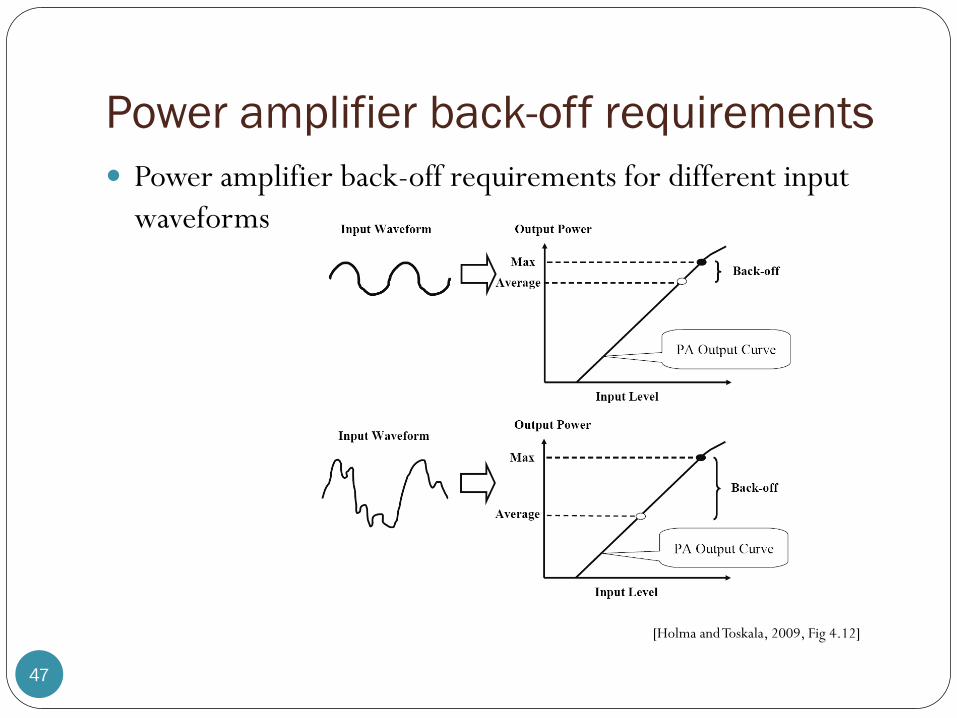
Power amplifier back-off requirements
47
Power amplifier back-off requirements for different input
waveforms
[Holma and Toskala, 2009, Fig 4.12]
SC/FDE
48
Single Carrier with Frequency Domain Equalization(SC/FDE)
For broadband multipath channels, conventional time domain equalizers are impractical because of the complexity (very long channel impulse response in the time domain).
Frequency domain equalization (FDE) is more practical for such channels.
Single carrier with frequency domain equalization (SC/FDE) technique is another way to fight the frequency-selective fading channel.
It delivers performance similar to OFDM with essentially the same overall complexity, even for long channel delay
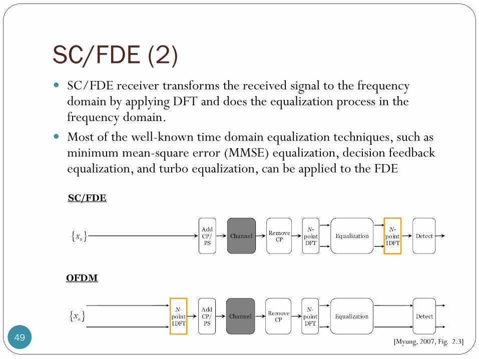
SC/FDE (2)
49
SC/FDE receiver transforms the received signal to the frequency domain by applying DFT and does the equalization process in the frequency domain.
Most of the well-known time domain equalization techniques, such as minimum mean-square error (MMSE) equalization, decision feedback equalization, and turbo equalization, can be applied to the FDE
[Myung, 2007, Fig. 2.3]

SC/FDE vs. OFDM (1)
50
OFDM performs data detection on a per-subcarrier basis in the frequency domain whereas SC/FDE does it in the time domain after the additional IDFT operation.
Because of this difference, OFDM is more sensitive to a null in the channel spectrum and it requires channel coding or power/rate control to overcome this deficiency.
OFDM
SC/FDE
[Myung, 2007, Fig. 2.4]

SC/FDE vs. OFDM (2)
51
The duration of the modulated time symbols are expanded in
the case of OFDM with parallel transmission of the data
block during the elongated time period.
[Myung, 2007, Fig. 2.4]
SC/FDE vs. OFDM (3)
52
SC/FDE has advantages over OFDM as follows:
Low PAPR due to single carrier modulation at the
transmitter.
Robustness to spectral null.
Lower sensitivity to carrier frequency offset.
Lower complexity at the transmitter which will benefit the
mobile terminal in cellular uplink communications.

SC-FDMA
53
Single carrier FDMA (SC-FDMA) is an extension of SC/FDE
to accommodate multi-user access.
[Holma and Toskala, 2009, Fig 4.13]

SC-FDMA vs. OFDMA
54 [Myung, 2007, Fig. 3.1]

SC-FDMA (2)
55
Lower peak-to-average power ratio (PAPR) because of its inherent single carrier structure. 2 to 6 dB PAR advantage over the OFDMA method used by other
technologies such as IEEE 802.16e.
Uplink direction for multiple access
Can be regarded as DFT-spread OFDMA, where time domain data symbols are transformed to frequency domain by DFT before going through OFDMA modulation.
The orthogonality of the users stems from the fact that each user occupies different subcarriers in the frequency domain, similar to the case of OFDMA.
QAM modulation, where each symbol is sent one at a time as in TDMA.
SC-FDMA (3)
56
Frequency domain generation of the signal adds the OFDMA property of good spectral waveform in contrast to time domain signal generation with a regular QAM modulator. The need for guard bands between different users can be avoided, similar to
the downlink OFDMA principle.
As in an OFDMA system, a cyclic prefix is also added periodically – but not after each symbol as the symbol rate is faster in the time domain than in OFDMA – to the transmission to prevent inter-symbol interference and to simplify the receiver design. The receiver still needs to deal with inter-symbol interference as the cyclic
prefi x now prevents inter-symbol interference between a block of symbols, and thus there will still be inter-symbol interference between the cyclic prefixes.
The receiver will thus run the equalizer for a block of symbols until reaching the cyclic prefix that prevents further propagation of the inter-symbol interference.

SC-FDMA: Subcarrier mapping
57


