
4-1
CHAPTER 4
MAJOR CONNECTORS
DEFINITION
The MAJOR CONNECTOR is thatpart of a RPD that joins the component partson one side of the arch to those on theopposite side.1 It is the unit of the RPD towhich all other parts are directly orindirectly attached.2
FUNCTIONS
The functions of the major connectorare to:
1. Join the various parts of aRPD so that the prosthesisacts as a single unit. A majorconnector must be rigid sothat the component parts donot function independentlyform one another. This way,forces applied to one part ofthe RPD are transmitted toother parts and are dissipatedby all teeth and tissuescontacted, rather than just bythose where the force isapplied.
2. Maxillary major connectorsfor tooth-tissue supportedRPDs provide some support,retention and direct-indirectretention(Fig. 4-1).
Fig. 4-1. � Full palatal coverage providingsome support, retention and indirectretention
3. Occasionally, in retrognathicjaw relationships, anteriorocclusion and incisalguidance is incorporated intothe anterior portion of themaxillary major connector(Fig. 4-2).
Fig. 4-2. � Occlusion provided on a palatalmajor connector-arrows indicate areas ofmandibular anterior tooth contact on themaxillary major connector
NOMENCLATURE
Major connectors are named by theirlocation and shape. Maxillary majorconnectors are located on the palate.Mandibular major connectors are usuallylocated on the lingual surface of the ridgeand teeth. Rarely, mandibular majorconnectors are located on the labial alveolarridge area or under the anterior part of thetongue.
Retentionfrom Post-palatal Seal
Supportfrom BroadPalatalCoverage
IndirectRetentionfromLingualPlate #6-#11

4-2
Major connectors are shaped as barsand straps or plates. A BAR-SHAPEDmajor connector is long, narrow, and thick.In cross section bars are ½ round, ½ oval or½ pear in shape (Fig. 4-3). The thickness ofa bar should be at least 6 gauge (4.11 mm) atits greatest dimension. The minimum widthof a bar is 4 mm, but they must usually bewider than this for adequate rigidity.
Fig. 4-3. � Shapes of bars, a) ½ pear, b) ½oval, c) ½ round
A STRAP or PLATE-SHAPEDmajor connector is long, wide and thin (Fig.4-4). The width of a strap or plate variesfrom 6 - 8 mm to the entire length of thepalate. The thickest portion of straps orplates is 22 - 24 gauge (0.64-0.51 mm).
Fig. 4-4. � A strap or plate
Frequently a strap or plate is addedto a bar extending the major connector onto
the tooth surfaces (Fig. 4-5). This issometimes called an APRON.
Fig. 4-5. � A strap or plate added to a bar toextend the major connector onto a a toothsurface
The location, width, thickness, andshape of a major connector should bedetermined by the dentist and RPDlaboratory technician based on theirknowledge of the physical properties of thealloy to be used for the framework and theanatomy of the partially edentulous arch.The more rigid the alloy, the smaller andthinner the framework may be. The biggerthe arch, the thicker and wider the majorconnector must be to provide the necessaryrigidity.
MANDIBULAR MAJORCONNECTORS
There are six mandibular majorconnectors described in the literature:lingual bar, lingual plate, lingual bar with acontinuous bar indirect retainer, labial bar(or plate), cingulum bar and sublingual bar.Of these, the lingual bar and lingual plateare used very frequently.3,4 The othermandibular major connectors are seldomindicated, or are advocated by fewpractitioners.
In this section the indications,contraindications, advantages anddisadvantages of each mandibular majorconnector is listed and the design of eachmajor connector and location of its bordersillustrated in the accompanying figures.
a
c
bb

4-3
LINGUAL BAR
SYNONYMS: ALVEOLAR BAR
Fig. 4-6. � LINGUAL BAR
Indications:1. The lingual bar is the
mandibular major connectorof choice if sufficient bracingand indirect retention can beprovided by clasps andindirect retainers; and iffuture additions of prostheticteeth to the framework toreplace extracted naturalteeth are not anticipated.
2. Diastemas or open cervicalembrasures of anterior teeth .
3. Overlapped anterior teeth.
Contraindications:1. Less than 8 mm between the
marginal gingiva and theactivated lingual frenum andfloor of the mouth.
2. Only a few remaininganterior teeth which must becontacted to provide areference for fitting theframework and indirectretention.
3. Lingually inclined teeth.4. An undercut lingual alveolar
ridge which would result inan excessive space between
the bar and the mucosa. (Fig.4-7).
Fig. 4-7. � An undercut lingual alveolarridge contraindicates the use of a lingual barbecause of the excessive space between thebar and mucosa
5. A parallel or sloped anteriorlingual alveolar contour in adistal extension RPD wherethe bar may rotate into thetissues as the denture basemoves toward the residualridge (Fig. 4-8).
Fig. 4-8. � A lingual bar is contraindicatedif the shape of the lingual alveolar ridge willresult in the bar rotating into the tissue as thebase moves toward the tissue around thefulcrum line (FL)
Advantages:1. Covers a minimum of surface
area of teeth and tissuestherefore the potential forcaries, periodontal problemsand mucositis caused byplaque being held in contactwith teeth and tissues isminimal.
2. Patients prefer lingual bar tolingual plate, probablybecause it is relatively small,inconspicuously located andminimally interferes withfunction.5,6.
FL

4-4
3. Esthetic.
Disadvantages:1. Not as rigid as the lingual
plate, sublingual bar orlingual bar with continuousbar indirect retainer.
2. Difficult to add additionalprosthetic teeth toframework.
3. Framework goes from thick(at the minor connectors) tothin (at the bar) to thick againwhich is metallurgically andstructurally complicated. Theresult may be weak areas inthe casting with the potentialto fracture.
LINGUAL PLATE
SYNONYMS: LINGUOPLATE,LINGUAL APRON, CLOSED KENNEDYMAJOR CONNECTOR.
Fig. 4-9. � LINGUAL PLATE
Indications:1. Less than 8 mm between the
marginal gingiva and theactivated lingual frenum andof the mouth.
2. Only a few remaininganterior teeth which must becontacted to provide areference for fitting theframework and indirectretention.
3. Undercut or parallel lingualalveolar ridge when thesuperior edge of a lingual barcan not be located in closecontact with the mucosa andstill be at least 3 mm inferiorto the marginal gingiva.
4. Distal extension RPDs withparallel or sloped lingualalveolar ridges where alingual bar would rotate intothe ridge when the base arearotates tissueward.
5. Mandibular tori or exostosiswhich must be covered by theRPD because they can not besurgically removed oravoided in the RPD design.Relief is provided betweenthe torus or exostosis and theframework.
Contraindications:1. A lingual bar may be used.2. Overlapped anterior teeth
where the undercuts in thearea of the superior edge ofthe plate can not be removed(Fig. 4-10). Frequently thiscriteria can not be met and alingual plate which will havesmall gaps between thesuperior edge of the plate andthe teeth must be used.

4-5
Fig. 4-10. � Undercuts in the area of thesuperior edge of a lingual plate must beremoved to allow contact of the plate withthe teeth
3. Lingually inclined teeth.4. Diastemas, unless the lingual
plate can have slots in it toavoid the display of metal(Fig. 4-11).
Fig. 4-11. � Placing slots in a lingual platewill prevent the metal showing throughdiastemas
5. Open cervical embrasureswhere the plate would bevisible (Fig. 4-12). A lingualbar with continuous barindirect retainer or a labialbar should be considered.
Fig. 4-12. � Open cervical embrasurescontraindicate the use of a lingual plate
Advantages:1. More rigid than a lingual bar.2. Metallurgically and
structurally simple.3. Easy to add additional
prosthetic teeth toframework.
4. May prevent supraerruptionof the teeth it contacts.
Disadvantages:1. Covers more tooth and tissue
surface than lingual bar.2. May be more noticeable to
patient than lingual bar.3. May cause flaring of incisors
if it contacts their cingula asthe base area rotatestissueward.
LINGUAL BAR WITH CONTINUOUSBAR INDIRECT RETAINER
SYNONYMS: KENNEDY BAR, SPLITLINGUAL BAR, DOUBLELINGUALBAR
Fig. 4-13. � LINGUAL BAR withCONTINUOUS BAR INDIRECTRETAINER
Indications:1. Situations where the major
connector must contact thenatural teeth to providebracing and indirect retentionand there are open cervicalembrasures whichcontraindicate the use of alingual plate. There must be
UndercutAreas
Incisal View

4-6
adequate space for the lingualbar portion of the majorconnector.
Contraindications:1. Where a lingual bar or
lingual plate will suffice.2. Any contraindication for a
lingual bar.3. Any contraindication for a
lingual plate except opencervical embrasures.
4. Diastemas.
Advantages:1. More rigid than lingual bar.2. Covers less tooth and tissue
surface than lingual plate.
Disadvantages:1. Very complex design.2. May be objectionable to
patient because there are fouredges exposed to the tip ofthe tongue.
LABIAL BAR (OR PLATE)
SYNONYMS: None
Fig. 4-14. � LABIAL BAR
Indications:1. Lingually inclined teeth
preventing the use of alingual mandibular majorconnector.
2. Lingual tori or exostoseswhich can not be removedsurgically, avoided in theRPD design, or covered by
the framework with adequaterelief.
3. A lingual major connectorcan not be used because ofthe slope or undercut of thelingual alveolus.
4. The patient can not tolerate alingual major connector.
5. Diastemas and open cervicalembrasures contraindicating alingual plate.
Contraindications:1. A lingual major connector
may be used.2. Facial tori or exostoses.3. The facial alveolar ridge is
undercut.4. High facial muscle
attachments which wouldresult in less than 3 mm ofspace between the superioredge of the labial bar and themarginal gingiva of the teeth.
Advantages:1. Can be used where lingual
major connector can not
Disadvantages:1. A labial major connector is
longer than a lingual majorconnector and, therefore,must be wider and/or thickeror larger to provide thenecessary rigidity.
2. A labial major connector maybe visible when the patientsmiles and it may distort lipcontour resulting in pooresthetics.
3. Difficult to add prostheticteeth to framework.

4-7
CINGULUM BAR
SYNONYMS: None
Fig. 4-15. � CINGULUM BAR
Indications:1. Height of activated lingual
frenum and floor of themouth at the same level asmarginal gingiva.
2. Inoperable tori or exostosesat the same level as themarginal gingiva.
3. Severely undercut lingualalveolus
4. Concern that a majorconnector traversing thegingival sulcus will cause aperiodontal problem.
5. Considerable gingivalrecession.
Contraindications:1. When a simpler major
connector may be used.2. Diastemas and open cervical
embrasures where the metalwill show.
Advantages:1. Can be used where lingual
bar and lingual plate can not.2. Does not traverse the
marginal gingiva or overlaythe lingual alveolus.
3. Easy to add prosthetic teethto framework.
Disadvantages:1. Must be bulky to have
sufficient rigidity and thusmay be objectionable to thepatient.
SUBLINGUAL BAR
SYNONYMS: None
Fig. 4-16. � SUBLINGUAL BAR
Indications:1. Bracing and indirect retention
can be provided by claspsand indirect retainers andfuture additions of prostheticteeth to the framework arenot anticipated.
2. Severely undercut lingualalveolar ridges.
3. Distal extension RPDsituations with sloped orparallel lingual alveolarridges where a lingual barwould rotate into the lingualalveolus as the base arearotates tissueward.
4. Diastemas and open cervicalembrasures of anterior teeth.
5. Overlapped anterior teeth.6. Intolerance to other lingual
major connectors.
Sagittalview ofBar

4-8
Contraindications:1. Where a lingual bar or
lingual plate will suffice.2. Situations where bracing
and/or indirect retention mustbe provided by contact of themajor connect with the teeth.
3. Situations where futureadditions of prosthetic teethto the framework areanticipated.
Advantages:1. Sublingual bar does not
contact anterior teeth orlingual alveolus.
2. More esthetic than otherlingual major connectorsbecause of its location.
3. More rigid than lingual barbecause bulk of metal ishorizontal rather thanvertical.
Disadvantages:1. Requires border molded
impression of floor of mouthfor accurate placement ofmajor connector.
2. Difficult to add prostheticteeth to framework.
3. Most patients prefer a lingualplate to a sublingual bar.5
MAXILLARY MAJOR CONNECTORS
The terminology for, and design of,maxillary major connectors is lessstandardized than for mandibular majorconnectors. There are six maxillary majorconnector designs in the literature: palatalstrap, palatal plate, complete palatalcoverage, anteroposterior type, U-shapedand palatal bar. The palatal plate andcomplete palatal coverage major connectorshave two distinct designs.
In this section the indications,contraindications, advantages anddisadvantages of each maxillary majorconnector is listed and the design of eachmajor connector and the location of itsborders illustrated in the accompanyingfigures.
PALATAL STRAP
SYNONYMS: PALATAL PLATE,MIDDLE PALATAL STRAP ORPLATE
Fig. 4-17. � PALATAL STRAPIndications:1. A Class III or Class III mod.
1 P partially edentulous arch.
Contraindications:1. Tooth-tissue supported RPD.2. Palatial torus.3. Extremely long tooth
supported edentulous space(A-P major connector wouldbe better because it wouldcover less palatal tissue.)
Advantages:1. Very simple design.2. Posterior border is well
anterior to the hamular notch-vibrating line.
3. Anterior border is posterior torugae ("playground of thetongue").
4. Very few metal-tissue edges.
4-9
Disadvantages:1. Covers a considerable portion
of the palate.
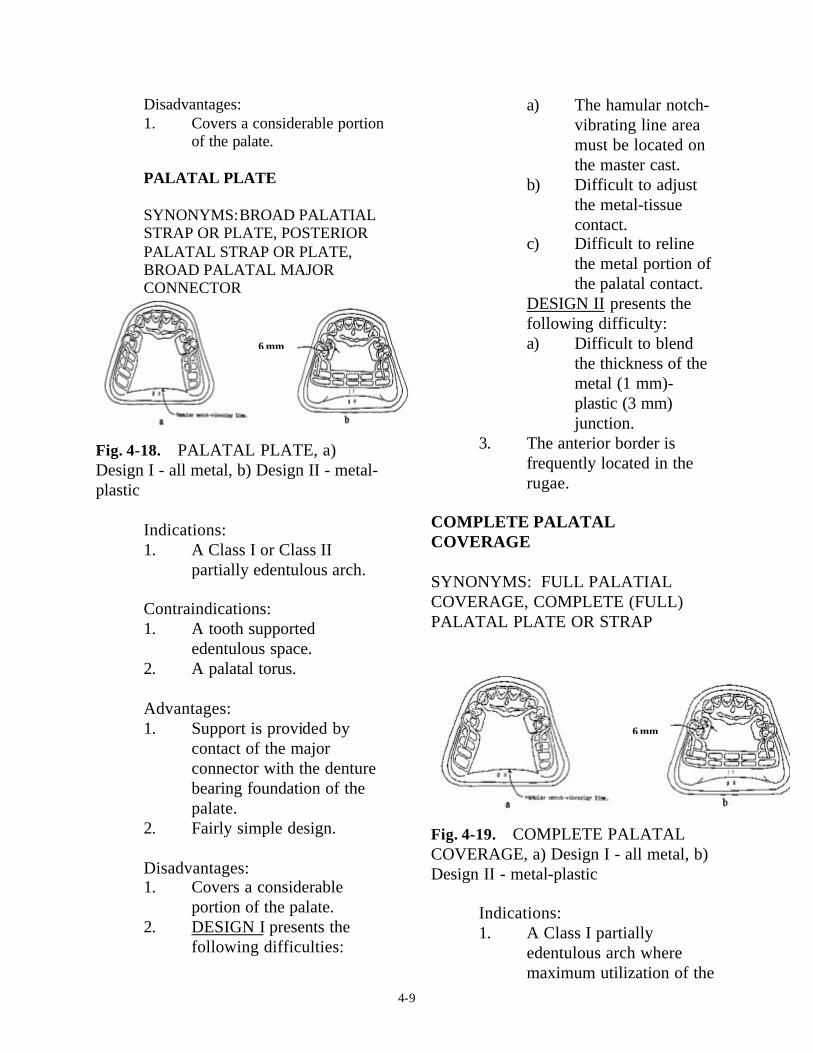
PALATAL PLATE
SYNONYMS:BROAD PALATIALSTRAP OR PLATE, POSTERIORPALATAL STRAP OR PLATE,BROAD PALATAL MAJORCONNECTOR
Fig. 4-18. � PALATAL PLATE, a)Design I - all metal, b) Design II - metal-plastic
Indications:1. A Class I or Class II
partially edentulous arch.
Contraindications:1. A tooth supported
edentulous space.2. A palatal torus.
Advantages:1. Support is provided by
contact of the majorconnector with the denturebearing foundation of thepalate.
2. Fairly simple design.
Disadvantages:1. Covers a considerable
portion of the palate.2. DESIGN I presents the
following difficulties:
a) The hamular notch-vibrating line areamust be located onthe master cast.
b) Difficult to adjustthe metal-tissuecontact.
c) Difficult to relinethe metal portion ofthe palatal contact.
DESIGN II presents thefollowing difficulty:a) Difficult to blend
the thickness of themetal (1 mm)-plastic (3 mm)junction.
3. The anterior border isfrequently located in therugae.
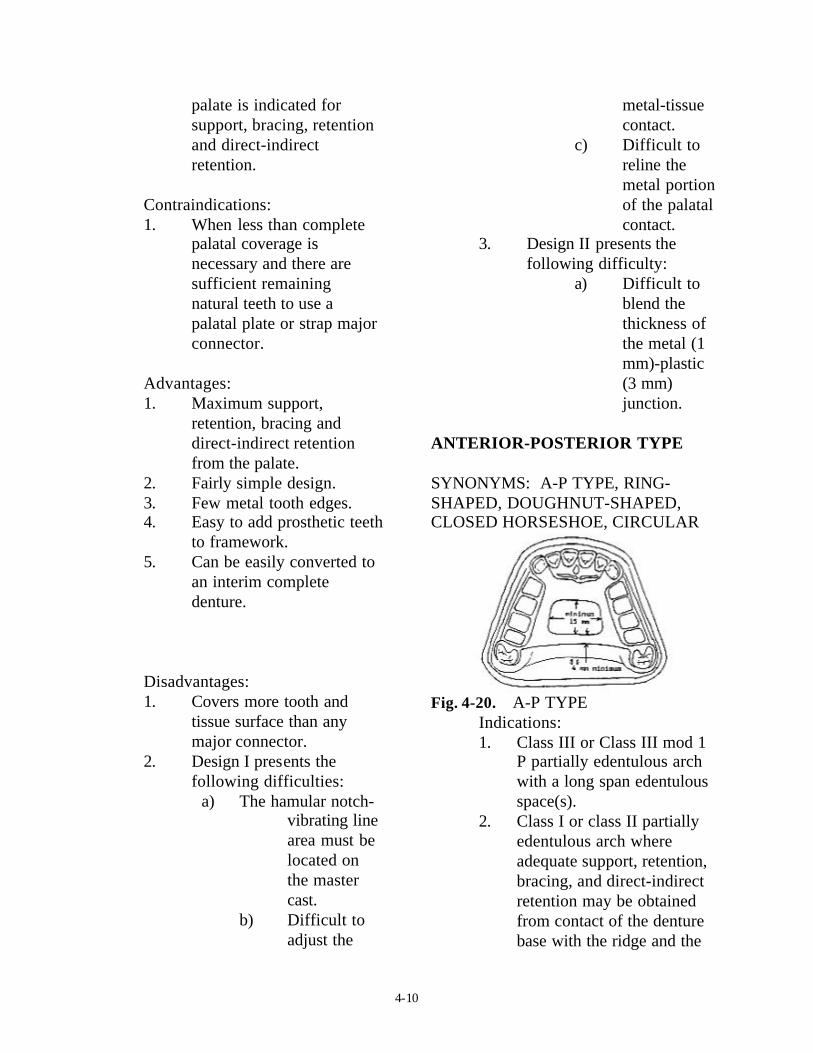
COMPLETE PALATALCOVERAGE
SYNONYMS: FULL PALATIALCOVERAGE, COMPLETE (FULL) PALATAL PLATE OR STRAP
Fig. 4-19. � COMPLETE PALATALCOVERAGE, a) Design I - all metal, b)Design II - metal-plastic
Indications:1. A Class I partially
edentulous arch wheremaximum utilization of the
6 mm
6 mm
4-10
palate is indicated forsupport, bracing, retentionand direct-indirectretention.
Contraindications:1. When less than complete
palatal coverage isnecessary and there aresufficient remainingnatural teeth to use apalatal plate or strap majorconnector.
Advantages:1. Maximum support,
retention, bracing anddirect-indirect retentionfrom the palate.
2. Fairly simple design.3. Few metal tooth edges.4. Easy to add prosthetic teeth
to framework.5. Can be easily converted to
an interim completedenture.
Disadvantages:1. Covers more tooth and
tissue surface than anymajor connector.
2. Design I presents thefollowing difficulties:
a) The hamular notch-vibrating linearea must belocated onthe mastercast.
b) Difficult toadjust the
metal-tissuecontact.
c) Difficult toreline themetal portionof the palatalcontact.
3. Design II presents thefollowing difficulty:
a) Difficult toblend thethickness ofthe metal (1mm)-plastic(3 mm)junction.
ANTERIOR-POSTERIOR TYPE
SYNONYMS: A-P TYPE, RING-SHAPED, DOUGHNUT-SHAPED,CLOSED HORSESHOE, CIRCULAR
Fig. 4-20. � A-P TYPEIndications:1. Class III or Class III mod 1
P partially edentulous archwith a long span edentulousspace(s).
2. Class I or class II partiallyedentulous arch whereadequate support, retention,bracing, and direct-indirectretention may be obtainedfrom contact of the denturebase with the ridge and the

4-11
contact of the frameworkwith the palate.
3. An inoperable palatal torus.4. A RPD replacing anterior
teeth.
Contraindications:1. Where the palatal opening
will be less than 15 mmanteroposteriorly ormediolaterally.
2. Where support, retention,bracing, and direct-indirectretention from the palate isrequired.
3. Where a major connectorwith a simpler design maybe used.
Advantages:1. Covers a minimum of
palatal tissues.
Disadvantages:1. Very complex design.2. A lot of metal-tissue edges.3. The posterior palatal bar or
strap frequently does not fitthe palate closely.
4. The anterior border isfrequently located in therugae.
5. The posterior border isfrequently located in thehamular notch-vibrating linearea.
U-SHAPED
SYNONYMS: ANTERIOR PALATALSTRAP, HORSESHOE, OPEN RING,OPEN DOUGHNUT
Fig. 4-21. � U-SHAPED
Indications:1. A Class IV partially
edentulous arch.2. A Class III or Class III mod
1 P partially edentulous archwith an anterior edentulousspace, where cross-archforce distribution is notimportant.
3. A partially edentulous archwith an inoperable palataltorus.
Contraindications:1. Where support, retention,
bracing, and direct-indirectretention from the palate isnecessary.
2. Where cross-arch forcedistribution is necessary.
Advantages:1. Minimal coverage of the
palate.2. Fairly simple design.3. Fewer metal-tooth or tissue
edges than the A-P design.
4-12
Disadvantages:1. Not as rigid as other
maxillary major connectors.Rigidity may be increasedby having the metal in thevertical and horizontalplanes and is probablyadequate, particularly withcast chromium alloyframeworks (Fig. 4-22).
Fig. 4-22. � Rigidity of a major connectoris increased by having the metal on twoplanes, a) vertical plane, b) horizontalplane
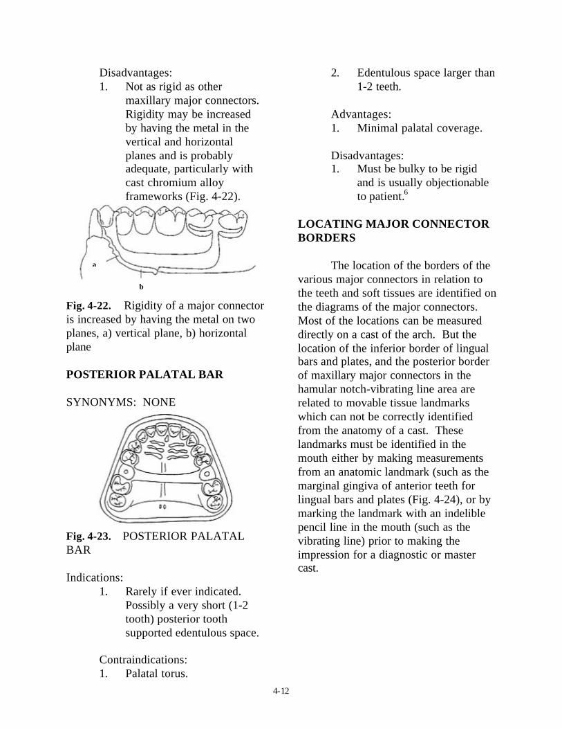
POSTERIOR PALATAL BAR
SYNONYMS: NONE
Fig. 4-23. � POSTERIOR PALATALBAR
Indications:1. Rarely if ever indicated.
Possibly a very short (1-2tooth) posterior toothsupported edentulous space.
Contraindications:1. Palatal torus.
2. Edentulous space larger than1-2 teeth.
Advantages:1. Minimal palatal coverage.
Disadvantages:1. Must be bulky to be rigid
and is usually objectionableto patient.6
LOCATING MAJOR CONNECTORBORDERS
The location of the borders of thevarious major connectors in relation tothe teeth and soft tissues are identified onthe diagrams of the major connectors.Most of the locations can be measureddirectly on a cast of the arch. But thelocation of the inferior border of lingualbars and plates, and the posterior borderof maxillary major connectors in thehamular notch-vibrating line area arerelated to movable tissue landmarkswhich can not be correctly identifiedfrom the anatomy of a cast. Theselandmarks must be identified in themouth either by making measurementsfrom an anatomic landmark (such as themarginal gingiva of anterior teeth forlingual bars and plates (Fig. 4-24), or bymarking the landmark with an indeliblepencil line in the mouth (such as thevibrating line) prior to making theimpression for a diagnostic or mastercast.
b
a

4-13
Fig. 4-24. � Evaluating mouth floor depth,a) measuring the distance from the lingualgingival margins to the activated lingualfrenum and floor of the mouth using aperiodontal probe, b) the measurements arerecorded on the clinical form “Evaluation ofthe Mouth for Partial Dentures” for furtheruse when designing an RPD and whenoutlining an RPD framework on a mastercast
Maxillary major connectorborders which traverse the arch shouldcross the palate at a right angle to themidline suture or through the valleybetween rugae (Fig. 4-25). Changes inanteroposterior location are made on thevertical slopes of the palate. If a rugaemust be traversed it is crossed abruptly.The rationale for this is to hide theborders of major connectors from thetongue as much as possible.
Fig. 4-25. � The borders of a maxillarymajor connector cross the palate at right
angles to the midpalatal suture and/ orthrough the valleys between rugaeCONTACT OF THE MAJORCONNECTORS WITH THETISSUES
Mandibular
The superior edge (1-2 mm) ofmandibular major connectors shouldcontact the teeth or tissues to prevent aspace which would allow food impactionand accumulation and/or would benoticeable to the patient. The majorconnector below this contact area shouldbe relieved to prevent contact of theframework with the teeth and/or tissues(Fig. 4-26). The amount of reliefdepends on the amount of anticipatedtissueward movement of the RPD plasticbase.
Fig. 4-26. � The superior edge ofmandibular major connectors contactsthe teeth or mucosa and the inferiorportion is relieved, a) the amount ofrelief depends on the shape of the lingualalveolus, b) sloped - no relief necessary,c) parallel - minimum relief, d) undercut- parallel block-out.
Maxillary
Maxillary major connectorscontact the palate. They are relievedfrom contact only in areas of tori, hardpalatal sutures, or other areas where themucosa is very thin. The edges ofmaxillary major connectors which are
a b c d

4-14
exposed to the tongue are BEADED toinsure their contact with the mucosa(Fig. 4-27). The bead is approximately1.0 mm wide and deep. It should beslightly shallower over the midlinesuture or other areas where the mucosa isvery thin. The bead seals the metal-tissue junction preventing food anddebris form being forced under the majorconnector as the patient swallows. Thebead is necessary to compensate for thedimensional inaccuracies of the materialsand techniques used to make RPDs, suchas: impression materials, cast materials,the duplication process, cast alloys,finishing and polishing the framework,etc. The bead also increases the rigidityof the framework, identifies where tofinish the metal, and creates a bulk ofmetal at the border so that the edges maybe thinned to blend in with the tissues sothey will be less noticeable to thepatient.8
Fig. 4-27. � Exposed edges of maxillarymajor connectors are beaded, a) the beadline scribed on the master cast, b) theresultant metal bead on the tissue surfaceof the major connector.
FINISH OF THE SURFACES OFMAJOR CONNECTORS
The POLISHED SURFACE (sideaway from the teeth and tissues) of RPDframeworks is finished smooth withrubber wheels and highly polished.
The TISSUE SURFACE (sidenext to the teeth and tissues) ofmandibular RPD frameworks is finishedsmooth with rubber wheels and highlypolished. The tissue surface or maxillaryRPD framework is only lightly smoothedwith rubber wheels and is not polishedsince this surface must contact themucosa of the palate.
SELECTION OF THE MAJORCONNECTOR
The selection of the majorconnector to be used for a RPD dependson many factors and is discussed inDesigning Removable Partial Dentures.
REFERENCES
1. The glossary of prosthodonticterms. 6th ed. St. Louis, C VMosby, 1994.
2. Henderson D, McGivney G P,Castleberry D J. McCracken'sremovable partial prosthodontics.7th ed. St. Louis: C V Mosby,
3. Henderson D. Major connectorsfor removable partial dentures:design and function. J. ProsthetDent 1973; 30:532-48.
4. Ward J E., Kazanoglu A., BurnsD.R.: Survey of major connectorusage in a dental school, in press.
5. Hansen C A, Campbell D J.Clinical comparison of two
a a
b
RPD

4-15
mandibular major connectordesigns: the sublingual bar andthe lingual plate. J Prosthet Dent1985; 54:805-809.
6. Campbell L D. Subjectivereactions to major connectordesigns for removable partialdentures. J Prosthet Dent 1977;37:507-16.
7. Wagner A G, Traweek F C.Comparison of major connectors
for removable partial dentures. JProsthet Dent 1982; 47:242-45.
8. Stratton R V, Wiebelt F J. A atlasof removable partial denturedesign. Chicago: Quintessence,1988:37.


