
Chapter 10 10-1 From Eqs. (10-4) and (10-5)
4 1 0.615 4 2
4 4 4W B
C CK K
C C C 3
Plot 100(KW KB)/ KW vs. C for 4 C 12 obtaining
We see the maximum and minimum occur at C = 4 and 12 respectively where Maximum = 1.36 % Ans., and Minimum = 0.743 % Ans. ______________________________________________________________________________ 10-2 A = Sdm dim(Auscu) = [dim (S) dim(d m)]uscu = kpsiinm dim(ASI) = [dim (S) dim(d m)]SI = MPammm
SI uscu uscu uscu
MPa mm6.894757 25.4 6.895 25.4 .
kpsi in
mm m
mA A A A Ans
For music wire, from Table 10-4:
Auscu = 201 kpsiinm, m = 0.145; what is ASI?
_____________________________________________________________________________
0-3 Given: Music wire, d = 2.5 mm, OD = 31 mm, plain ground ends, Nt = 14 coils.
ASI = 6.895(25.4)0.145 (201) = 2215 MPammm Ans. _ 1
Chapter 10 - Rev. A, Page 1/41

(a) Table 10-1: Na = N 1 = 14 1 = 13 coils
Ls = d Nt = 2.5(14) = 35 mm
Table 10-4: m = 0.145, A = 2211 MPammm
Eq. (10-14):
t
0.145
22111936 MPa
2.5ut m
AS
d
Table 10-6: Ssy = 0.45(1936) = 871.2 MPa
D = OD d = 31 2.5 = 28.5 mm
C = D/d = 28.5/2.5 = 11.4
Eq. (10-5):
4 11.4 24 21.117
4 3 4 11.4 3B
CK
C
Eq. (10-7):
33 2.5 871.2167.9 N
8 8 1.117 28.5sy
sB
d SF
K D
Table 10-5): d = 2.5/25.4 = 0.098 in G = 81.0(103) MPa
Eq. (10-9):
4 34
3 3
2.5 81 101.314 N / mm
8 8 28.5 13a
d Gk
D N
0
167.935 162.8 mm .
1.314s
s
FL L A
k ns
(b) Fs = 167.9 N Ans.
(c) k = 1.314 N/mm Ans.
(d) 0 cr
149.9 mm0.5
L . Spring needs to be supported. Ans. 2.63 28.5
_____________________________________________________________________________
0-4 Given: Design load, F1 = 130 N.
4, N = 13 coils, Ssy = 871.2 MPa, Fs = 167.9 N,
Eq. (10-19): 3 ≤ Na ≤ 15 Na = 13 O.K.
_ 1 Referring to Prob. 10-3 solution, C = 11. a
L0 = 162.8 mm and (L0)cr = 149.9 mm. Eq. (10-18): 4 ≤ C ≤ 12 C = 11.4 O.K.
Chapter 10 - Rev. A, Page 2/41

Eq. (10-17): 1
167.91 1 0.29
130sF
F
Eq. (10-20): 0.15, 0.29 . .O K From Eq. (10-7) for static service
11 3 3
1
8 8(130)(28.5)1.117 674 MPa
(2.5)871.2
1.29674
B
sy
F DK
dS
n
Eq. (10-21): ns ≥ 1.2, n = 1.29 O.K.
1
167.9 167.9674 870.5 MPa
130 130/ 871.2 / 870.5 1
s
sy sS
Ssy/s ≥ (ns )d : Not solid-safe (but was the basis of the design). Not O.K. L0 ≤ (L0)cr: 162.8 149.9 Not O.K. Design is unsatisfactory. Operate over a rod? Ans. ______________________________________________________________________________ 10-5 Given: Oil-tempered wire, d = 0.2 in, D = 2 in, Nt = 12 coils, L0 = 5 in, squared ends. (a) Table 10-1: Ls = d (Nt + 1) = 0.2(12 + 1) = 2.6 in Ans. (b) Table 10-1: Na = Nt 2 = 12 2 = 10 coils Table 10-5: G = 11.2 Mpsi
Eq. (10-9):
4 64
3 3
0.2 11.2 1028 lbf/in
8 8 2 10
d Gk
D N
Fs = k ys = k (L0 Ls ) = 28(5 2.6) = 67.2 lbf Ans. (c) Eq. (10-1): C = D/d = 2/0.2 = 10
Eq. (10-5):
4 10 24 21.135
4 3 4 10 3B
CK
C
Eq. (10-7): 3
3 3
8 67.2 281.135 48.56 10 psi
0.2s B
FDK
d
Chapter 10 - Rev. A, Page 3/41

Table 10-4: m = 0.187, A = 147 kpsiinm
Eq. (10-14): 0.187
147198.6 kpsi
0.2ut m
AS
d
Table 10-6: Ssy = 0.50 Sut = 0.50(198.6) = 99.3 kpsi
99.3
2.04 .48.56
sys
s
Sn A
ns
______________________________________________________________________________ 10-6 Given: Oil-tempered wire, d = 4 mm, C = 10, plain ends, L0 = 80 mm, and at F = 50 N, y = 15 mm. (a) k = F/y = 50/15 = 3.333 N/mm Ans. (b) D = Cd = 10(4) = 40 mm OD = D + d = 40 + 4 = 44 mm Ans. (c) From Table 10-5, G = 77.2 GPa
Eq. (10-9):
4 34
3 3
4 77.2 1011.6 coils
8 8 3.333 40a
d GN
kD
Table 10-1: Nt = Na = 11.6 coils Ans. (d) Table 10-1: Ls = d (Nt + 1) = 4(11.6 + 1) = 50. 4 mm Ans. (e) Table 10-4: m = 0.187, A = 1855 MPammm
Eq. (10-14): 0.187
18551431 MPa
4ut m
AS
d
Table 10-6: Ssy = 0.50 Sut = 0.50(1431) = 715.5 MPa ys = L0 Ls = 80 50.4 = 29.6 mm Fs = k ys = 3.333(29.6) = 98.66 N
Eq. (10-5): 4 2 4(10) 2
1.1354 3 4(10) 3B
CK
C
Chapter 10 - Rev. A, Page 4/41

Eq. (10-7):
3 3
8 98.66 4081.135 178.2 MPa
4s
s B
F DK
d
715.5
4.02 .178.2
sys
s
Sn A
ns
______________________________________________________________________________ 10-7 Static service spring with: HD steel wire, d = 0.080 in, OD = 0.880 in, Nt = 8 coils, plain
and ground ends. Preliminaries Table 10-5: A = 140 kpsi · inm, m = 0.190
Eq. (10-14): 0.190
140226.2 kpsi
0.080ut m
AS
d
Table 10-6: Ssy = 0.45(226.2) = 101.8 kpsi Then, D = OD d = 0.880 0.080 = 0.8 in Eq. (10-1): C = D/d = 0.8/0.08 = 10
Eq. (10-5): 4 2 4(10) 2
1.1354 3 4(10) 3B
CK
C
Table 10-1: Na = Nt 1 = 8 1 = 7 coils Ls = dNt = 0.08(8) = 0.64 in Eq. (10-7) For solid-safe, ns = 1.2 :
3 33 0.08 101.8 10 / 1.2/
18.78 lbf8 8(1.135)(0.8)
sy ss
B
d S nF
K D
Eq. (10-9): 4 64
3 3
0.08 11.5 1016.43 lbf/in
8 8 0.8 7a
d Gk
D N
18.78
1.14 in16.43
ss
Fy
k
(a) L0 = ys + Ls = 1.14 + 0.64 = 1.78 in Ans.
(b) Table 10-1: 0 1.780.223 in .
8t
Lp A
N ns
(c) From above: Fs = 18.78 lbf Ans. (d) From above: k = 16.43 lbf/in Ans.
(e) Table 10-2 and Eq. (10-13): 0 cr
2.63 2.63(0.8)( ) 4.21 in
0.5
DL
Since L0 < (L0)cr, buckling is unlikely Ans. ______________________________________________________________________________ 10-8 Given: Design load, F1 = 16.5 lbf. Referring to Prob. 10-7 solution, C = 10, Na = 7 coils, Ssy = 101.8 kpsi, Fs = 18.78 lbf, ys = 1.14 in, L0 = 1.78 in, and (L0)cr = 4.208 in.
Chapter 10 - Rev. A, Page 5/41
Eq. (10-18): 4 ≤ C ≤ 12 C = 10 O.K. Eq. (10-19): 3 ≤ Na ≤ 15 Na = 7 O.K.
Eq. (10-17): 1
18.781 1 0.14
16.5sF
F
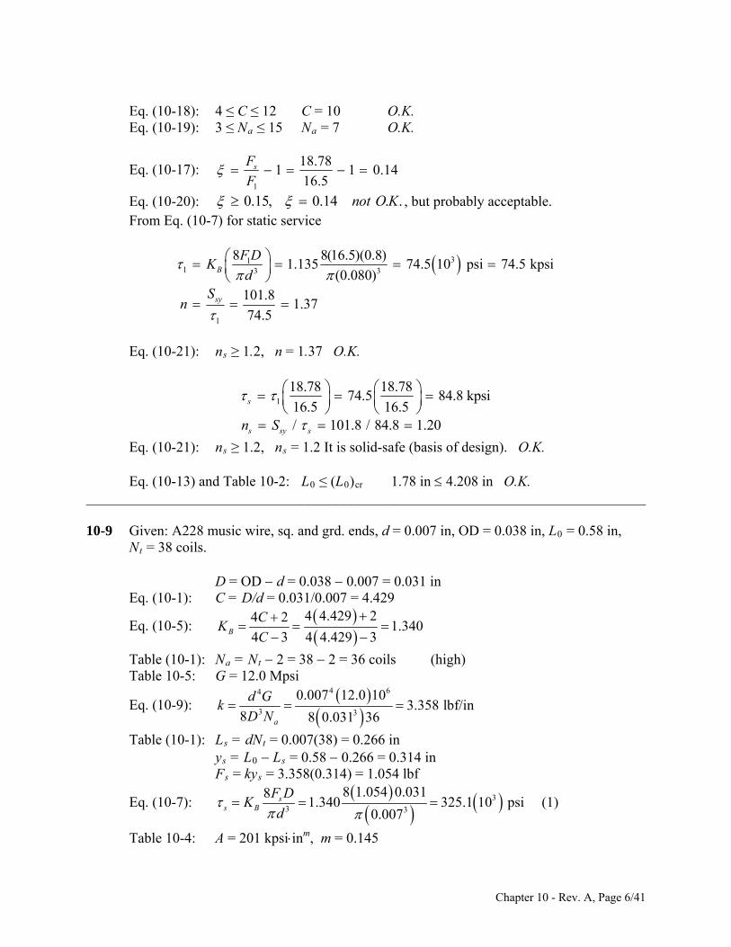
Eq. (10-20): 0.15, 0.14 . .not O K , but probably acceptable. From Eq. (10-7) for static service
311 3 3
1
8 8(16.5)(0.8)1.135 74.5 10 psi 74.5 kpsi
(0.080)101.8
1.3774.5
B
sy
F DK
dS
n
Eq. (10-21): ns ≥ 1.2, n = 1.37 O.K.
1
18.78 18.7874.5 84.8 kpsi
16.5 16.5/ 101.8 / 84.8 1.20
s
s sy sn S
Eq. (10-21): ns ≥ 1.2, ns = 1.2 It is solid-safe (basis of design). O.K. Eq. (10-13) and Table 10-2: L0 ≤ (L0)cr 1.78 in 4.208 in O.K. ______________________________________________________________________________ 10-9 Given: A228 music wire, sq. and grd. ends, d = 0.007 in, OD = 0.038 in, L0 = 0.58 in, Nt = 38 coils. D = OD d = 0.038 0.007 = 0.031 in Eq. (10-1): C = D/d = 0.031/0.007 = 4.429
Eq. (10-5):
4 4.429 24 21.340
4 3 4 4.429 3B
CK
C
Table (10-1): Na = Nt 2 = 38 2 = 36 coils (high) Table 10-5: G = 12.0 Mpsi
Eq. (10-9):
4 64
3 3
0.007 12.0 103.358 lbf/in
8 8 0.031 36a
d Gk
D N
Table (10-1): Ls = dNt = 0.007(38) = 0.266 in ys = L0 Ls = 0.58 0.266 = 0.314 in Fs = kys = 3.358(0.314) = 1.054 lbf
Eq. (10-7): 3
3 3
8 1.054 0.03181.340 325.1 10 psi
0.007s
s B
F DK
d
(1)
Table 10-4: A = 201 kpsiinm, m = 0.145
Chapter 10 - Rev. A, Page 6/41

Eq. (10-14): 0.145
201412.7 kpsi
0.007ut m
AS
d
Table 10-6: Ssy = 0.45 Sut = 0.45(412.7) = 185.7 kpsi s > Ssy, that is, 325.1 > 185.7 kpsi, the spring is not solid-safe. Return to Eq. (1) with Fs = kys and s = Ssy /ns, and solve for ys, giving
3 33 185.7 10 /1.2 0.007/0.149 in
8 8 1.340 3.358 0.031sy s
sB
S n dy
K kD
The free length should be wound to L0 = Ls + ys = 0.266 + 0.149 = 0.415 in Ans. This only addresses the solid-safe criteria. There are additional problems. ______________________________________________________________________________ 10-10 Given: B159 phosphor-bronze, sq. and grd. ends, d = 0.014 in, OD = 0.128 in, L0 = 0.50
in, Nt = 16 coils. D = OD d = 0.128 0.014 = 0.114 in Eq. (10-1): C = D/d = 0.114/0.014 = 8.143
Eq. (10-5):
4 8.143 24 21.169
4 3 4 8.143 3B
CK
C
Table (10-1): Na = Nt 2 = 16 2 = 14 coils Table 10-5: G = 6 Mpsi
Eq. (10-9):
4 64
3 3
0.014 6 101.389 lbf/in
8 8 0.114 14a
d Gk
D N
Table (10-1): Ls = dNt = 0.014(16) = 0.224 in ys = L0 Ls = 0.50 0.224 = 0.276 in Fs = kys = 1.389(0.276) = 0.3834 lbf
Eq. (10-7):
33 3
8 0.3834 0.11481.169 47.42 10 psi
0.014s
s B
F DK
d
(1)
Table 10-4: A = 145 kpsiinm, m = 0
Eq. (10-14): 0
145145 kpsi
0.014ut m
AS
d
Table 10-6: Ssy = 0.35 Sut = 0.35(135) = 47.25 kpsi s > Ssy, that is, 47.42 > 47.25 kpsi, the spring is not solid-safe. Return to Eq. (1) with Fs = kys and s = Ssy /ns, and solve for ys, giving
3 33 47.25 10 /1.2 0.014/0.229 in
8 8 1.169 1.389 0.114sy s
sB
S n dy
K kD
The free length should be wound to
Chapter 10 - Rev. A, Page 7/41

L0 = Ls + ys = 0.224 + 0.229 = 0.453 in Ans. ______________________________________________________________________________ 10-11 Given: A313 stainless steel, sq. and grd. ends, d = 0.050 in, OD = 0.250 in, L0 = 0.68 in,
Nt = 11.2 coils. D = OD d = 0.250 0.050 = 0.200 in Eq. (10-1): C = D/d = 0.200/0.050 = 4
Eq. (10-5):
4 4 24 21.385
4 3 4 4 3B
CK
C
Table (10-1): Na = Nt 2 = 11.2 2 = 9.2 coils Table 10-5: G = 10 Mpsi
Eq. (10-9):
4 64
3 3
0.050 10 10106.1 lbf/in
8 8 0.2 9.2a
d Gk
D N
Table (10-1): Ls = dNt = 0.050(11.2) = 0.56 in ys = L0 Ls = 0.68 0.56 = 0.12 in Fs = kys = 106.1(0.12) = 12.73 lbf
Eq. (10-7): 3
3 3
8 12.73 0.281.385 71.8 10 psi
0.050s
s B
F DK
d
Table 10-4: A = 169 kpsiinm, m = 0.146
Eq. (10-14): 0.146
169261.7 kpsi
0.050ut m
AS
d
Table 10-6: Ssy = 0.35 Sut = 0.35(261.7) = 91.6 kpsi
91.6
1.2871.8
sys
s
Sn
Spring is solid-safe (ns > 1.2) Ans.
______________________________________________________________________________ 10-12 Given: A227 hard-drawn wire, sq. and grd. ends, d = 0.148 in, OD = 2.12 in, L0 = 2.5 in,
Nt = 5.75 coils. D = OD d = 2.12 0.148 = 1.972 in Eq. (10-1): C = D/d = 1.972/0.148 = 13.32 (high)
Eq. (10-5):
4 13.32 24 21.099
4 3 4 13.32 3B
CK
C
Table (10-1): Na = Nt 2 = 5.75 2 = 3.75 coils Table 10-5: G = 11.4 Mpsi
Eq. (10-9):
4 64
3 3
0.148 11.4 1023.77 lbf/in
8 8 1.972 3.75a
d Gk
D N
Table (10-1): Ls = dNt = 0.148(5.75) = 0.851 in ys = L0 Ls = 2.5 0.851 = 1.649 in
Chapter 10 - Rev. A, Page 8/41

Fs = kys = 23.77(1.649) = 39.20 lbf
Eq. (10-7): 3
3 3
8 39.20 1.97281.099 66.7 10 psi
0.148s
s B
F DK
d
Table 10-4: A = 140 kpsiinm, m = 0.190
Eq. (10-14): 0.190
140201.3 kpsi
0.148ut m
AS
d
Table 10-6: Ssy = 0.35 Sut = 0.45(201.3) = 90.6 kpsi
90.6
1.3666.7
sys
s
Sn
Spring is solid-safe (ns > 1.2) Ans.
______________________________________________________________________________ 10-13 Given: A229 OQ&T steel, sq. and grd. ends, d = 0.138 in, OD = 0.92 in, L0 = 2.86 in, Nt = 12 coils. D = OD d = 0.92 0.138 = 0.782 in Eq. (10-1): C = D/d = 0.782/0.138 = 5.667
Eq. (10-5):
4 5.667 24 21.254
4 3 4 5.667 3B
CK
C
Table (10-1): Na = Nt 2 = 12 2 = 10 coils A229 OQ&T steel is not given in Table 10-5. From Table A-5, for carbon steels, G = 11.5 Mpsi.
Eq. (10-9):
4 64
3 3
0.138 11.5 10109.0 lbf/in
8 8 0.782 10a
d Gk
D N
Table (10-1): Ls = dNt = 0.138(12) = 1.656 in ys = L0 Ls = 2.86 1.656 = 1.204 in Fs = kys = 109.0(1.204) = 131.2 lbf
Eq. (10-7): 3
3 3
8 131.2 0.78281.254 124.7 10 psi
0.138s
s B
F DK
d
(1)
Table 10-4: A = 147 kpsiinm, m = 0.187
Eq. (10-14): 0.187
147212.9 kpsi
0.138ut m
AS
d
Table 10-6: Ssy = 0.50 Sut = 0.50(212.9) = 106.5 kpsi s > Ssy, that is, 124.7 > 106.5 kpsi, the spring is not solid-safe. Return to Eq. (1) with Fs = kys and s = Ssy /ns, and solve for ys, giving
3 33 106.5 10 /1.2 0.138/0.857 in
8 8 1.254 109.0 0.782sy s
sB
S n dy
K kD
The free length should be wound to
Chapter 10 - Rev. A, Page 9/41

L0 = Ls + ys = 1.656 + 0.857 = 2.51 in Ans. ______________________________________________________________________________ 10-14 Given: A232 chrome-vanadium steel, sq. and grd. ends, d = 0.185 in, OD = 2.75 in, L0 =
7.5 in, Nt = 8 coils. D = OD d = 2.75 0.185 = 2.565 in Eq. (10-1): C = D/d = 2.565/0.185 = 13.86 (high)
Eq. (10-5):
4 13.86 24 21.095
4 3 4 13.86 3B
CK
C
Table (10-1): Na = Nt 2 = 8 2 = 6 coils Table 10-5: G = 11.2 Mpsi.
Eq. (10-9):
4 64
3 3
0.185 11.2 1016.20 lbf/in
8 8 2.565 6a
d Gk
D N
Table (10-1): Ls = dNt = 0.185(8) = 1.48 in ys = L0 Ls = 7.5 1.48 = 6.02 in Fs = kys = 16.20(6.02) = 97.5 lbf
Eq. (10-7): 3
3 3
8 97.5 2.56581.095 110.1 10 psi
0.185s
s B
F DK
d
(1)
Table 10-4: A = 169 kpsiinm, m = 0.168
Eq. (10-14): 0.168
169224.4 kpsi
0.185ut m
AS
d
Table 10-6: Ssy = 0.50 Sut = 0.50(224.4) = 112.2 kpsi
112.2
1.02110.1
sys
s
Sn
Spring is not solid-safe (ns < 1.2)
Return to Eq. (1) with Fs = kys and s = Ssy /ns, and solve for ys, giving
3 33 112.2 10 /1.2 0.185/5.109 in
8 8 1.095 16.20 2.565sy s
sB
S n dy
K kD
The free length should be wound to L0 = Ls + ys = 1.48 + 5.109 = 6.59 in Ans. ______________________________________________________________________________ 10-15 Given: A313 stainless steel, sq. and grd. ends, d = 0.25 mm, OD = 0.95 mm, L0 = 12.1
mm, Nt = 38 coils. D = OD d = 0.95 0.25 = 0.7 mm Eq. (10-1): C = D/d = 0.7/0.25 = 2.8 (low)
Eq. (10-5):
4 2.8 24 21.610
4 3 4 2.8 3B
CK
C
Chapter 10 - Rev. A, Page 10/41

Table (10-1): Na = Nt 2 = 38 2 = 36 coils (high) Table 10-5: G = 69.0(103) MPa.
Eq. (10-9):
4 34
3 3
0.25 69.0 102.728 N/mm
8 8 0.7 36a
d Gk
D N
Table (10-1): Ls = dNt = 0.25(38) = 9.5 mm ys = L0 Ls = 12.1 9.5 = 2.6 mm Fs = kys = 2.728(2.6) = 7.093 N
Eq. (10-7): 3 3
8 7.093 0.781.610 1303 MPa
0.25s
s B
F DK
d
(1)
Table 10-4 (dia. less than table): A = 1867 MPammm, m = 0.146
Eq. (10-14): 0.146
18672286 MPa
0.25ut m
AS
d
Table 10-6: Ssy = 0.35 Sut = 0.35(2286) = 734 MPa s > Ssy, that is, 1303 > 734 MPa, the spring is not solid-safe. Return to Eq. (1) with Fs = kys and s = Ssy /ns, and solve for ys, giving
33 734 /1.2 0.25/1.22 mm
8 8 1.610 2.728 0.7sy s
sB
S n dy
K kD
The free length should be wound to L0 = Ls + ys = 9.5 + 1.22 = 10.72 mm Ans. This only addresses the solid-safe criteria. There are additional problems. ______________________________________________________________________________ 10-16 Given: A228 music wire, sq. and grd. ends, d = 1.2 mm, OD = 6.5 mm, L0 = 15.7 mm, Nt = 10.2 coils. D = OD d = 6.5 1.2 = 5.3 mm Eq. (10-1): C = D/d = 5.3/1.2 = 4.417
Eq. (10-5):
4 4.417 24 21.368
4 3 4 4.417 3B
CK
C
Table (10-1): Na = Nt 2 = 10.2 2 = 8.2 coils Table 10-5 (d = 1.2/25.4 = 0.0472 in): G = 81.7(103) MPa.
Eq. (10-9): 4 34
3 3
1.2 81.7 1017.35 N/mm
8 8 5.3 8.2a
d Gk
D N
Table (10-1): Ls = dNt = 1.2(10.2) = 12.24 mm ys = L0 Ls = 15.7 12.24 = 3.46 mm Fs = kys = 17.35(3.46) = 60.03 N
Chapter 10 - Rev. A, Page 11/41

Eq. (10-7):
3 3
8 60.03 5.381.368 641.4 MPa
1.2s
s B
F DK
d
(1)
Table 10-4: A = 2211 MPammm, m = 0.145
Eq. (10-14): 0.145
22112153 MPa
1.2ut m
AS
d
Table 10-6: Ssy = 0.45 Sut = 0.45(2153) = 969 MPa
969
1.51641.4
sys
s
Sn
Spring is solid-safe (ns > 1.2) Ans.
______________________________________________________________________________ 10-17 Given: A229 OQ&T steel, sq. and grd. ends, d = 3.5 mm, OD = 50.6 mm, L0 = 75.5 mm, Nt = 5.5 coils. D = OD d = 50.6 3.5 = 47.1 mm Eq. (10-1): C = D/d = 47.1/3.5 = 13.46 (high)
Eq. (10-5):
4 13.46 24 21.098
4 3 4 13.46 3B
CK
C
Table (10-1): Na = Nt 2 = 5.5 2 = 3.5 coils A229 OQ&T steel is not given in Table 10-5. From Table A-5, for carbon steels, G = 79.3(103) MPa.
Eq. (10-9):
4 34
3 3
3.5 79.3 104.067 N/mm
8 8 47.1 3.5a
d Gk
D N
Table (10-1): Ls = dNt = 3.5(5.5) = 19.25 mm ys = L0 Ls = 75.5 19.25 = 56.25 mm Fs = kys = 4.067(56.25) = 228.8 N
Eq. (10-7):
3 3
8 228.8 47.181.098 702.8 MPa
3.5s
s B
F DK
d
(1)
Table 10-4: A = 1855 MPammm, m = 0.187
Eq. (10-14): 0.187
18551468 MPa
3.5ut m
AS
d
Table 10-6: Ssy = 0.50 Sut = 0.50(1468) = 734 MPa
734
1.04702.8
sys
s
Sn
Spring is not solid-safe (ns < 1.2)
Return to Eq. (1) with Fs = kys and s = Ssy /ns, and solve for ys, giving
33 734 /1.2 3.5/48.96 mm
8 8 1.098 4.067 47.1sy s
sB
S n dy
K kD
The free length should be wound to
Chapter 10 - Rev. A, Page 12/41
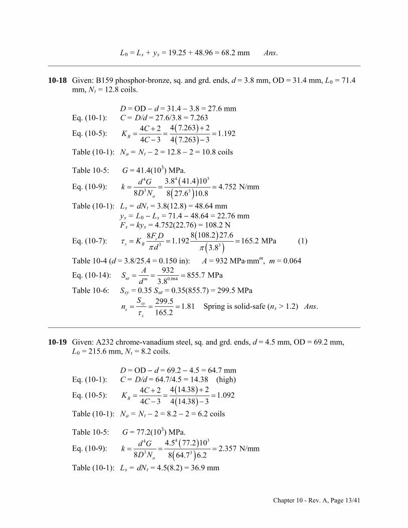
L0 = Ls + ys = 19.25 + 48.96 = 68.2 mm Ans. ______________________________________________________________________________ 10-18 Given: B159 phosphor-bronze, sq. and grd. ends, d = 3.8 mm, OD = 31.4 mm, L0 = 71.4
mm, Nt = 12.8 coils. D = OD d = 31.4 3.8 = 27.6 mm Eq. (10-1): C = D/d = 27.6/3.8 = 7.263
Eq. (10-5):
4 7.263 24 21.192
4 3 4 7.263 3B
CK
C
Table (10-1): Na = Nt 2 = 12.8 2 = 10.8 coils Table 10-5: G = 41.4(103) MPa.
Eq. (10-9):
4 34
3 3
3.8 41.4 104.752 N/mm
8 8 27.6 10.8a
d Gk
D N
Table (10-1): Ls = dNt = 3.8(12.8) = 48.64 mm ys = L0 Ls = 71.4 48.64 = 22.76 mm Fs = kys = 4.752(22.76) = 108.2 N
Eq. (10-7):
3 3
8 108.2 27.681.192 165.2 MPa
3.8s
s B
F DK
d
(1)
Table 10-4 (d = 3.8/25.4 = 0.150 in): A = 932 MPammm, m = 0.064
Eq. (10-14): 0.064
932855.7 MPa
3.8ut m
AS
d
Table 10-6: Ssy = 0.35 Sut = 0.35(855.7) = 299.5 MPa
299.5
1.81165.2
sys
s
Sn
Spring is solid-safe (ns > 1.2) Ans.
______________________________________________________________________________ 10-19 Given: A232 chrome-vanadium steel, sq. and grd. ends, d = 4.5 mm, OD = 69.2 mm, L0 = 215.6 mm, Nt = 8.2 coils. D = OD d = 69.2 4.5 = 64.7 mm Eq. (10-1): C = D/d = 64.7/4.5 = 14.38 (high)
Eq. (10-5):
4 14.38 24 21.092
4 3 4 14.38 3B
CK
C
Table (10-1): Na = Nt 2 = 8.2 2 = 6.2 coils Table 10-5: G = 77.2(103) MPa.
Eq. (10-9):
4 34
3 3
4.5 77.2 102.357 N/mm
8 8 64.7 6.2a
d Gk
D N
Table (10-1): Ls = dNt = 4.5(8.2) = 36.9 mm
Chapter 10 - Rev. A, Page 13/41

ys = L0 Ls = 215.6 36.9 = 178.7 mm Fs = kys = 2.357(178.7) = 421.2 N
Eq. (10-7):
3 3
8 421.2 64.781.092 832 MPa
4.5s
s B
F DK
d
(1)
Table 10-4: A = 2005 MPammm, m = 0.168
Eq. (10-14): 0.168
20051557 MPa
4.5ut m
AS
d
Table 10-6: Ssy = 0.50 Sut = 0.50(1557) = 779 MPa s > Ssy, that is, 832 > 779 MPa, the spring is not solid-safe. Return to Eq. (1) with Fs = kys and s = Ssy /ns, and solve for ys, giving
33 779 /1.2 4.5/139.5 mm
8 8 1.092 2.357 64.7sy s
sB
S n dy
K kD
The free length should be wound to L0 = Ls + ys = 36.9 + 139.5 = 176.4 mm Ans. This only addresses the solid-safe criteria. There are additional problems. ______________________________________________________________________________ 10-20 Given: A227 HD steel. From the figure: L0 = 4.75 in, OD = 2 in, and d = 0.135 in. Thus
D = OD d = 2 0.135 = 1.865 in (a) By counting, Nt = 12.5 coils. Since the ends are squared along 1/4 turn on each end,
12.5 0.5 12 turns .4.75 / 12 0.396 in .
aN Ansp Ans
The solid stack is 13 wire diameters
Ls = 13(0.135) = 1.755 in Ans. (b) From Table 10-5, G = 11.4 Mpsi
4 64
3 3
0.135 (11.4) 106.08 lbf/in .
8 8 1.865 (12)a
d Gk A
D N ns
(c) Fs = k(L0 - Ls ) = 6.08(4.75 1.755)(10-3) = 18.2 lbf Ans. (d) C = D/d = 1.865/0.135 = 13.81
Chapter 10 - Rev. A, Page 14/41

3
3 3
4(13.81) 21.096
4(13.81) 38 8(18.2)(1.865)
1.096 38.5 10 psi 38.5 kpsi .0.135
B
ss B
K
F DK A
d
ns
______________________________________________________________________________
10-21 For the wire diameter analyzed, G = 11.75 Mpsi per Table 10-5. Use squared and ground ends. The following is a spread-sheet study using Fig. 10-3 for parts (a) and (b). For Na, k = Fmax /y = 20/2 = 10 lbf/in. For s, F = Fs = 20(1 + ) = 20(1 + 0.15) = 23 lbf.
(a) Spring over a Rod (b) Spring in a Hole Source Parameter Values Source Parameter Values
d 0.075 0.080 0.085 d 0.075 0.080 0.085 ID 0.800 0.800 0.800 OD 0.950 0.950 0.950 D 0.875 0.880 0.885 D 0.875 0.870 0.865 Eq. (10-1) C 11.667 11.000 10.412 Eq. (10-1) C 11.667 10.875 10.176 Eq. (10-9) Na 6.937 8.828 11.061 Eq. (10-9) Na 6.937 9.136 11.846 Table 10-1 Nt 8.937 10.828 13.061 Table 10-1 Nt 8.937 11.136 13.846 Table 10-1 Ls 0.670 0.866 1.110 Table 10-1 Ls 0.670 0.891 1.177 1.15y + Ls L0 2.970 3.166 3.410 1.15y + Ls L0 2.970 3.191 3.477 Eq. (10-13) (L0)cr 4.603 4.629 4.655 Eq. (10-
13) (L0)cr 4.603 4.576 4.550
Table 10-4 A 201.000 201.000 201.000 Table 10-4 A 201.000 201.000 201.000 Table 10-4 m 0.145 0.145 0.145 Table 10-4 m 0.145 0.145 0.145 Eq. (10-14) Sut 292.626 289.900 287.363 Eq. (10-
14) Sut 292.626 289.900 287.363
Table 10-6 Ssy 131.681 130.455 129.313 Table 10-6 Ssy 131.681 130.455 129.313 Eq. (10-5) KB 1.115 1.122 1.129 Eq. (10-5) KB 1.115 1.123 1.133 Eq. (10-7) s 135.335 112.948 95.293 Eq. (10-7) s 135.335 111.787 93.434 Eq. (10-3) ns 0.973 1.155 1.357 Eq. (10-3) ns 0.973 1.167 1.384 Eq. (10-22) fom 0.282 0.391 0.536 Eq. (10-
22) fom 0.282 0.398 0.555
For ns ≥ 1.2, the optimal size is d = 0.085 in for both cases. ______________________________________________________________________________ 10-22 In Prob. 10-21, there is an advantage of first selecting d as one can select from the
available sizes (Table A-28). Selecting C first, requires a calculation of d where then a size must be selected from Table A-28.
Consider part (a) of the problem. It is required that ID = D d = 0.800 in. (1) From Eq. (10-1), D = Cd. Substituting this into the first equation yields
0.800
1d
C (2)
Chapter 10 - Rev. A, Page 15/41

Starting with C = 10, from Eq. (2) we find that d = 0.089 in. From Table A-28, the closest diameter is d = 0.090 in. Substituting this back into Eq. (1) gives D = 0.890 in, with C = 0.890/0.090 = 9.889, which are acceptable. From this point the solution is the same as Prob. 10-21. For part (b), use
OD = D + d = 0.950 in. (3)
and, 0.800
1C
(4) d
(a) Spring over a rod (b) Spring in a Hole
Source Parameter Values Source Parameter Values C 10.000 10.5 C 10.000
Eq. (2) d 0.089 0.084 Eq. (4) d 0.086 Table A-28 d 0.090 0.085 Table A-28 d 0.085
Eq. (1) D 0.890 0.885 Eq. (3) D 0.865 Eq. (10-1) C 9.889 10.412 Eq. (10-1) C 10.176 Eq. (10-9) Na 13.669 11.061 Eq. (10-9) Na 11.846 Table 10-1 Nt 15.669 13.061 Table 10-1 Nt 13.846 Table 10-1 Ls 1.410 1.110 Table 10-1 Ls 1.177 1.15y + Ls L0 3.710 3.410 1.15y + Ls L0 3.477 Eq. (10-13) (L0)cr 4.681 4.655 Eq. (10-13) (L0)cr 4.550 Table 10-4 A 201.000 201.000 Table 10-4 A 201.000 Table 10-4 m 0.145 0.145 Table 10-4 m 0.145 Eq. (10-14) Sut 284.991 287.363 Eq. (10-14) Sut 287.363 Table 10-6 Ssy 128.246 129.313 Table 10-6 Ssy 129.313 Eq. (10-5) KB 1.135 1.128 Eq. (10-5) KB 1.135 Eq. (10-7) s 81.167 95.223 Eq. (10-7) s 93.643 ns = Ssy/s ns 1.580 1.358 ns = Ssy/s ns 1.381 Eq. (10-22) fom -0.725 -0.536 Eq. (10-22) fom -0.555
Again, for ns 1.2, the optimal size is = 0.085 in. Although this approach used less iterations than in Prob. 10-21, this was due to the initial
values picked and not the approach. ______________________________________________________________________________ 10-23 One approach is to select A227 HD steel for its low cost. Try L0 = 48 mm, then for y = 48 37.5 = 10.5 mm when F = 45 N. The spring rate is k = F/y = 45/10.5 = 4.286
N/mm. For a clearance of 1.25 mm with screw, ID = 10 + 1.25 = 11.25 mm. Starting with d = 2 mm, D = ID + d = 11.25 + 2 = 13.25 mm C = D/d = 13.25/2 = 6.625 (acceptable) Table 10-5 (d = 2/25.4 = 0.0787 in): G = 79.3 GPa
Chapter 10 - Rev. A, Page 16/41

Eq. (10-9): 4 4 3
3 3
2 (79.3)1015.9 coils
8 8(4.286)13.25a
d G
kD N
Assume squared and closed. Table 10-1: Nt = Na + 2 = 15.9 + 2 = 17.9 coils Ls = dNt = 2(17.9) =35.8 mm ys = L0 Ls = 48 35.8 = 12.2 mm Fs = kys = 4.286(12.2) = 52.29 N
Eq. (10-5):
4 6.625 24 2
1.213B
CK
4 3 4 6.625 3C
Eq. (10-7): 3
8 8(52.291.213s
s B
F DK
3
)13.25267.5 MPa
2d
Table 10-4: A = 1783 MPa · mmm, m = 0.190
Eq. (10-14): 0.190
17831563 MPa
2ut m
AS
d
Table 10-6: Ssy = 0.45Sut = 0.45(1563) = 703.3 MPa
703.3
2.63 1.2 . .267.5
sys
s
Sn O K
No other diameters in the given range work. So specify A227-47 HD steel, d = 2 mm, D = 13.25 mm, ID = 11.25 mm, OD = 15.25 mm, squared
and closed, Nt = 17.9 coils, Na = 15.9 coils, k = 4.286 N/mm, Ls = 35.8 mm, and L0 = 48 mm. Ans.
______________________________________________________________________________ 10-24 Select A227 HD steel for its low cost. Try L0 = 48 mm, then for y = 48 37.5 = 10.5 mm
when F = 45 N. The spring rate is k = F/y = 45/10.5 = 4.286 N/mm. For a clearance of 1.25 mm with screw, ID = 10 + 1.25 = 11.25 mm. D d = 11.25 (1) and, D =Cd (2) Starting with C = 8, gives D = 8d. Substitute into Eq. (1) resulting in d = 1.607 mm.
Selecting the nearest diameter in the given range, d = 1.6 mm. From this point, the calculations are shown in the third column of the spreadsheet output shown. We see that for d = 1.6 mm, the spring is not solid safe. Iterating on C we find that C = 6.5 provides acceptable results with the specifications
A227-47 HD steel, d = 2 mm, D = 13.25 mm, ID = 11.25 mm, OD = 15.25 mm, squared
Chapter 10 - Rev. A, Page 17/41
and closed, Nt = 17.9 coils, Na = 15.9 coils, k = 4.286 N/mm, Ls = 35.8 mm, and L0 = 48 mm. Ans.
Chapter 10 - Rev. A, Page 18/41

Source Parameter Values C 8.000 7 6.500
Eq. (2) d 1.607 1.875 2.045 Table A-28 d 1.600 1.800 2.000
Eq. (1) D 12.850 13.050 13.250 Eq. (10-1) C 8.031 7.250 6.625 Eq. (10-9) Na 7.206 10.924 15.908 Table 10-1 Nt 9.206 12.924 17.908 Table 10-1 Ls 14.730 23.264 35.815
L0 Ls ys 33.270 24.736 12.185 Fs = kys Fs 142.594 106.020 52.224
Table 10-4 A 1783.000 1783.000 1783.000 Table 10-4 m 0.190 0.190 0.190 Eq. (10-14) Sut 1630.679 1594.592 1562.988 Table 10-6 Ssy 733.806 717.566 703.345 Eq. (10-5) KB 1.172 1.200 1.217 Eq. (10-7) s 1335.568 724.943 268.145 ns = Ssy/s ns 0.549 0.990 2.623
The only difference between selecting C first rather than d as was done in Prob. 10-23, is
that once d is calculated, the closest wire size must be selected. Iterating on d uses available wire sizes from the beginning.
______________________________________________________________________________ 10-25 A stock spring catalog may have over two hundred pages of compression springs with up
to 80 springs per page listed. • Students should be made aware that such catalogs exist. • Many springs are selected from catalogs rather than designed. • The wire size you want may not be listed. • Catalogs may also be available on disk or the web through search routines. For
example, disks are available from Century Spring at 1 - (800) - 237 - 5225
www.centuryspring.com • It is better to familiarize yourself with vendor resources rather than invent them
yourself. • Sample catalog pages can be given to students for study. ______________________________________________________________________________ 10-26 Given: ID = 0.6 in, C = 10, L0 = 5 in, Ls = 5 3 = 2 in, sq. & grd ends, unpeened, HD
A227 wire. (a) With ID = D d = 0.6 in and C = D/d = 10 10 d d = 0.6 d = 0.0667 in Ans., and D = 0.667 in. (b) Table 10-1: Ls = dNt = 2 in Nt = 2/0.0667 30 coils Ans.
Chapter 10 - Rev. A, Page 19/41

(c) Table 10-1: Na = Nt 2 = 30 2 = 28 coils Table 10-5: G = 11.5 Mpsi
Eq. (10-9): 4 64
3 3
0.0667 11.5 103.424 lbf/in .
8 8 0.667 28a
d Gk Ans
D N
(d) Table 10-4: A = 140 kpsiinm, m = 0.190
Eq. (10-14): 0.190
234.2 kpsi0.0667ut m
Sd
140A
Table 10-6: Ssy = 0.45 Sut = 0.45 (234.2) = 105.4 kpsi Fs = kys = 3.424(3) = 10.27 lbf
4 10 24 21.135
4 3 4 10 3B
CK
C
Eq. (10-5):
Eq. (10-7):
366.72 10 psi 66.72 kpsi
K
3 3
8 10.27 0.66781.135
0.0667s
s B
F D
d
105.41.58 .
66.72sy
s
n A s
Sns
(e) a = m = 0.5s = 0.5(66.72) = 33.36 kpsi, r = a / m = 1. Using the Gerber fatigue failure criterion with Zimmerli data,
Eq. (10-30): Ssu = 0.67 Sut = 0.67(234.2) = 156.9 kpsi The Gerber ordinate intercept for the Zimmerli data is
2 2
3539.9 kpsi
1 / 1 55 /156.9sa
e
sm su
SS
S S
Table 6-7, p. 307,
22 2 21 1
2
i
su sesa
se su
r S SS
S rS
22 21 156.9 2 39.91 1 37.61 kps
2 39.9 1 156.9 37.61
1.13 .33.36
saf
a
Sn Ans
______________________________________________________________________________ 10-27 Given: OD 0.9 in, C = 8, L0 = 3 in, Ls = 1 in, ys = 3 1 = 2 in, sq. ends, unpeened,
music wire. (a) Try OD = D + d = 0.9 in, C = D/d = 8 D = 8d 9d = 0.9 d = 0.1 Ans.
Chapter 10 - Rev. A, Page 20/41
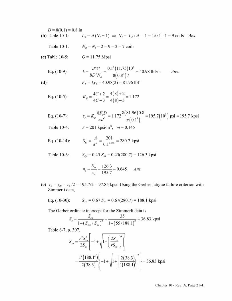
D = 8(0.1) = 0.8 in (b) Table 10-1: Ls = d (Nt + 1) Nt = Ls / d 1 = 1/0.1 1 = 9 coils Ans. Table 10-1: Na = Nt 2 = 9 2 = 7 coils (c) Table 10-5: G = 11.75 Mpsi
Eq. (10-9): 4 64
3 3
0.1 11.75 1040.98 lbf/in .
8 8 0.8 7a
d Gk Ans
D N
(d) Fs = kys = 40.98(2) = 81.96 lbf
Eq. (10-5): 4 8 24 2
1.1724 3 4 8 3B
CK
C
Eq. (10-7): 3
3 3
8 81.96 0.881.172 195.7 10 psi 195.7 kpsi
0.1s
s B
F DK
d
Table 10-4: A = 201 kpsiinm, m = 0.145
Eq. (10-14): 0.145
201280.7 kpsi
0.1ut m
A
d S
Table 10-6: Ssy = 0.45 Sut = 0.45(280.7) = 126.3 kpsi
126.30.645 .sy
s
Sn A
195.7s
ns
(e) a = m = s /2 = 195.7/2 = 97.85 kpsi. Using the Gerber fatigue failure criterion with
Zimmerli data, Eq. (10-30): Ssu = 0.67 Sut = 0.67(280.7) = 188.1 kpsi The Gerber ordinate intercept for the Zimmerli data is
2 2
/ 1 55 /188.1sm suS S
3536.83 kpsi
1sa
e
SS
Table 6-7, p. 307,
22 2
22 2
21 1
2
1 188.1 2 38.31 1 36.83 kpsi
2 38.3 1 188.1
su sesa
se su
r S SS
S rS
Chapter 10 - Rev. A, Page 21/41

36.830.376
97.85sa
a
.f
Sn Ans
Obviously, the spring is severely under designed and will fail statically and in fatigue.
Increasing C would improve matters. Try C = 12. This yields ns = 1.83 and nf = 1.00. ______________________________________________________________________________ 10-28 Note to the Instructor: In the first printing of the text, the wire material was incorrectly
identified as music wire instead of oil-tempered wire. This will be corrected in subsequent printings. We are sorry for any inconvenience.
Given: Fmax = 300 lbf, Fmin = 150 lbf, y = 1 in, OD = 2.1 0.2 = 1.9 in, C = 7,
unpeened, sq. & grd., oil-tempered wire. (a) D = OD d = 1.9 d (1) C = D/d = 7 D = 7d (2) Substitute Eq. (2) into (1) 7d = 1.9 d d = 1.9/8 = 0.2375 in Ans. (b) From Eq. (2): D = 7d = 7(0.2375) = 1.663 in Ans.
300 150150 lbf/in .
1
Fk A
y
(c) ns
(d) Table 10-5: G = 11.6 Mpsi
Eq. (10-9): 4 64
3 3
0.2375 11.6 106.69 coils
8 8 1.663 150a
d GN
D k
Table 10-1: Nt = Na + 2 = 8.69 coils Ans. (e) Table 10-4: A = 147 kpsiinm, m = 0.187
Eq. (10-14): 0.187
147192.3 kpsi
0.2375ut m
A
d S
Table 10-6: Ssy = 0.5 Sut = 0.5(192.3) = 96.15 kpsi
Eq. (10-5): 4 7 24 2
1.24 3 4 7 3B
CK
C
Chapter 10 - Rev. A, Page 22/41

Eq. (10-7): 3
8 ss B sy
F DK S
d
3 33 0.2375 96.15 10253.5 lbfsy
s
d SF
8 8 1.2 1.663BK D
ys = Fs / k = 253.5/150 = 1.69 in Table 10-1: Ls = Nt d = 8.46(0.2375) = 2.01 in L0 = Ls + ys = 2.01 + 1.69 = 3.70 in Ans. ______________________________________________________________________________ 10-29 For a coil radius given by:
2 11
-
2
R RR R
N
The torsion of a section is T = PR where dL = R d
23
0
32
2 110
24
2 11
2 10
4 4 2 22 1 1 2 1 2
2 1
4 2 21 2 1 24
1 1
2
1 2
4 2
( )2 ( ) 2
16 ( )
32
N
P
N
N
p
U TT dL PR d
P GJ P GJP R R
R dGJ N
P N R RR
GJ R R N
PN PNR R R R R R
GJ R R GJPN
J d R R R RGd
4
2 21 2 1 2
.16 ( )P
P d Gk Ans
N R R R R
______________________________________________________________________________ 10-30 Given: Fmin = 4 lbf, Fmax = 18 lbf, k = 9.5 lbf/in, OD 2.5 in, nf = 1.5. For a food service machinery application select A313 Stainless wire. Table 10-5: G = 10(106) psi Note that for 0.013 ≤ d ≤ 0.10 in A = 169, m = 0.146 0.10 < d ≤ 0.20 in A = 128, m = 0.263
18 4 18 4
7 lbf , 11 lbf , 7 / 112 2a m r
F F
Chapter 10 - Rev. A, Page 23/41

Try, 0.146
1690.080 in, 244.4 kpsi
(0.08)ut d S
Ssu = 0.67Sut = 163.7 kpsi, Ssy = 0.35Sut = 85.5 kpsi Try unpeened using Zimmerli’s endurance data: Ssa = 35 kpsi, Ssm = 55 kpsi
Gerber: 2 2
3539.5 kpsi
1 ( / ) 1 (55 / 163.7)sa
sesm su
S
S S
S
22 2
3 32 2
(7 / 11) (163.7) 2(39.5)1 1 35.0 kpsi
2(39.5) (7 / 11)(163.7)
/ 35.0 / 1.5 23.3 kpsi
8 8(7)(10 ) (10 ) 2.785 kpsi
(0.08 )
2(23.3) 2.785 2(23.3) 2.785
4(2.785) 4(2.785)
sa
sa f
a
S
S n
F
d
C
2
33 3
4 6
3
3(23.3)6.97
4(2.785)
6.97(0.08) 0.558 in4 2 4(6.97) 2
1.2014 3 4(6.97) 3
8 8(7)(0.558)1.201 (10 ) 23.3 kpsi
(0.08 )35 / 23.3 1.50 checks
10(10 )(0.0
8
B
aa B
f
a
D CdC
KC
F DK
dn
GdN
kD
4
3
max max
max
0
0
8)31.02 coils
8(9.5)(0.558)31.02 2 33 coils, 0.08(33) 2.64 in
/ 18 / 9.5 1.895 in(1 ) (1 0.15)(1.895) 2.179 in2.64 2.179 4.819 in
2.63(0.558)( ) 2.63 2.935 in
0.5
t s t
s
cr
s
N L dNy F k
y yL
DL
2 2 2 2
1.15(18 / 7) 1.15(18 / 7)(23.3) 68.9 kpsi/ 85.5 / 68.9 1.24
9.5(386)109 Hz
(0.08 )(0.558)(31.02)(0.283)
a
s sy s
a
kgf
d DN
n S
These steps are easily implemented on a spreadsheet, as shown below, for different
diameters.
Chapter 10 - Rev. A, Page 24/41

d1 d2 d3 d4
d 0.080 0.0915 0.1055 0.1205
m 0.146 0.146 0.263 0.263
A 169.000 169.000 128 128
Sut 244.363 239.618 231.257 223.311
Ssu 163.723 160.544 154.942 149.618
Ssy 85.527 83.866 80.940 78.159
Sse 39.452 39.654 40.046 40.469
Ssa 35.000 35.000 35.000 35.000
23.333 23.333 23.333 23.333
2.785 2.129 1.602 1.228
C 6.977 9.603 13.244 17.702
D 0.558 0.879 1.397 2.133
KB 1.201 1.141 1.100 1.074
a 23.333 23.333 23.333 23.333nf 1.500 1.500 1.500 1.500
Na 30.993 13.594 5.975 2.858
Nt 32.993 15.594 7.975 4.858
LS 2.639 1.427 0.841 0.585
ys 2.179 2.179 2.179 2.179
L0 4.818 3.606 3.020 2.764
(L0)cr 2.936 4.622 7.350 11.220
s 69.000 69.000 69.000 69.000
ns 1.240 1.215 1.173 1.133
f,(Hz) 108.895 114.578 118.863 121.775
The shaded areas depict conditions outside the recommended design conditions. Thus,
one spring is satisfactory. The specifications are: A313 stainless wire, unpeened, squared and ground, d = 0.0915 in, OD = 0.879 + 0.092 = 0.971 in, L0 = 3.606 in, and Nt = 15.59 turns Ans.
______________________________________________________________________________ 10-31 The steps are the same as in Prob. 10-23 except that the Gerber-Zimmerli criterion is
replaced with Goodman-Zimmerli:
1sa
sesm su
SS
S S
Chapter 10 - Rev. A, Page 25/41

The problem then proceeds as in Prob. 10-23. The results for the wire sizes are shown below (see solution to Prob. 10-23 for additional details).
Iteration of d for the first trial d1 d2 d3 d4 d1 d2 d3 d4 d 0.080 0.0915 0.1055 0.1205 d 0.080 0.0915 0.1055 0.1205m 0.146 0.146 0.263 0.263 KB 1.151 1.108 1.078 1.058A 169.000 169.000 128.000 128.000 a 29.008 29.040 29.090 29.127Sut 244.363 239.618 231.257 223.311 nf 1.500 1.500 1.500 1.500Ssu 163.723 160.544 154.942 149.618 Na 14.191 6.456 2.899 1.404Ssy 85.527 83.866 80.940 78.159 Nt 16.191 8.456 4.899 3.404Sse 52.706 53.239 54.261 55.345 Ls 1.295 0.774 0.517 0.410Ssa 43.513 43.560 43.634 43.691 ymax 2.875 2.875 2.875 2.875 29.008 29.040 29.090 29.127 L0 4.170 3.649 3.392 3.285 2.785 2.129 1.602 1.228 (L0)cr 3.809 5.924 9.354 14.219C 9.052 12.309 16.856 22.433 s 85.782 85.876 86.022 86.133D 0.724 1.126 1.778 2.703 ns 0.997 0.977 0.941 0.907
f (Hz) 140.040 145.559 149.938 152.966
Without checking all of the design conditions, it is obvious that none of the wire sizes satisfy ns ≥ 1.2. Also, the Gerber line is closer to the yield line than the Goodman. Setting nf = 1.5 for Goodman makes it impossible to reach the yield line (ns < 1) . The table below uses nf = 2.
Iteration of d for the second trial d1 d2 d3 d4 d1 d2 d3 d4 d 0.080 0.0915 0.1055 0.1205 d 0.080 0.0915 0.1055 0.1205m 0.146 0.146 0.263 0.263 KB 1.221 1.154 1.108 1.079A 169.000 169.000 128.000 128.000 a 21.756 21.780 21.817 21.845Sut 244.363 239.618 231.257 223.311 nf 2.000 2.000 2.000 2.000Ssu 163.723 160.544 154.942 149.618 Na 40.243 17.286 7.475 3.539Ssy 85.527 83.866 80.940 78.159 Nt 42.243 19.286 9.475 5.539Sse 52.706 53.239 54.261 55.345 Ls 3.379 1.765 1.000 0.667Ssa 43.513 43.560 43.634 43.691 ymax 2.875 2.875 2.875 2.875 21.756 21.780 21.817 21.845 L0 6.254 4.640 3.875 3.542 2.785 2.129 1.602 1.228 (L0)cr 2.691 4.266 6.821 10.449C 6.395 8.864 12.292 16.485 s 64.336 64.407 64.517 64.600D 0.512 0.811 1.297 1.986 ns 1.329 1.302 1.255 1.210
f (Hz) 98.936 104.827 109.340 112.409 The satisfactory spring has design specifications of: A313 stainless wire, unpeened,
squared and ground, d = 0.0915 in, OD = 0.811 + 0.092 = 0.903 in, L0 = 4.266 in, and .Nt = 19.6 turns. Ans. ______________________________________________________________________________ 10-32 This is the same as Prob. 10-30 since Ssa = 35 kpsi. Therefore, the specifications are:
Chapter 10 - Rev. A, Page 26/41

A313 stainless wire, unpeened, squared and ground, d = 0.0915 in, OD = 0.879 + 0.092 = 0.971 in, L0 = 3.606 in, and Nt = 15.84 turns Ans.
______________________________________________________________________________ 10-33 For the Gerber fatigue-failure criterion, Ssu = 0.67Sut ,
22 2
2
2, 1 1
1 ( / ) 2sa su se
se sasm su se su
S r S SS S
S S S rS
The equation for Ssa is the basic difference. The last 2 columns of diameters of Ex. 10-5
are presented below with additional calculations.
d 0.105 0.112 d 0.105 0.112 Sut 278.691 276.096 Na 8.915 6.190 Ssu 186.723 184.984 Ls 1.146 0.917 Sse 38.325 38.394 L0 3.446 3.217 Ssy 125.411 124.243 (L0)cr 6.630 8.160 Ssa 34.658 34.652 KB 1.111 1.095 23.105 23.101 a 23.105 23.101 1.732 1.523 nf 1.500 1.500 C 12.004 13.851 s 70.855 70.844 D 1.260 1.551 ns 1.770 1.754 ID 1.155 1.439 fn 105.433 106.922 OD 1.365 1.663 fom 0.973 1.022
There are only slight changes in the results. ______________________________________________________________________________ 10-34 As in Prob. 10-35, the basic change is Ssa.
For Goodman, 1 - ( / )
sase
sm su
SS S
S
Recalculate Ssa with
se susa
su se
rS SS
rS S
Calculations for the last 2 diameters of Ex. 10-5 are given below.
Chapter 10 - Rev. A, Page 27/41
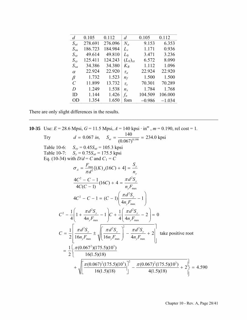
d 0.105 0.112 d 0.105 0.112 Sut 278.691 276.096 Na 9.153 6.353 Ssu 186.723 184.984 Ls 1.171 0.936 Sse 49.614 49.810 L0 3.471 3.236 Ssy 125.411 124.243 (L0)cr 6.572 8.090 Ssa 34.386 34.380 KB 1.112 1.096 22.924 22.920 a 22.924 22.920 1.732 1.523 nf 1.500 1.500 C 11.899 13.732 s 70.301 70.289 D 1.249 1.538 ns 1.784 1.768 ID 1.144 1.426 fn 104.509 106.000 OD 1.354 1.650 fom 0.986 1.034
There are only slight differences in the results. ______________________________________________________________________________ 10-35 Use: E = 28.6 Mpsi, G = 11.5 Mpsi, A = 140 kpsi · inm , m = 0.190, rel cost = 1.
Try 0.190
1400.067 , 234.0 kpsi
(0.067)utd in S
Table 10-6: Ssy = 0.45Sut = 105.3 kpsi Table 10-7: Sy = 0.75Sut = 175.5 kpsi Eq. (10-34) with D/d = C and C1 = C
max ySF2
22
max
22
max
[( ) (16 ) 4]
4 1(16 ) 4
4 ( 1)
4 1 ( 1) 14
A Ay
y
y
y
y
K Cd n
d SC CC
C C n F
d SC C C
n F
2 22
max max
1 11 1 2 0
4 4 4 4y y
y y
d S d SC C
n F n F
22 2 2
max max max
2 3
22 3 2 3
12 take positive root
2 16 16 4
1 (0.067 )(175.5)(10 )
2 16(1.5)(18)
(0.067) (175.5)(10 ) (0.067) (175.5)(10 )
16(1.5)(18) 4(
y y y
y y y
d S d S d SC
n F n F n F
2 4.590
1.5)(18)
Chapter 10 - Rev. A, Page 28/41

3 3
4.59 0.067 0.3075 in
33 500 31000 4
8 8 exp(0.105 ) 6.5i
i
D Cd
d d CF
D D C
Use the lowest Fi in the preferred range. This results in the best fom.
3(0.067) 33 500 4.590 31000 4 6.505 lbf
8(0.3075) exp[0.105(4.590)] 6.5iF
For simplicity, we will round up to the next integer or half integer. Therefore, use Fi = 7
lbf
4 4 6
3 3
0
18 lbf
18 722 lbf/in
0.5(0.067) (11.5)(10 )
45.28 turns8 8(22)(0.3075)
11.545.28 44.88 turns
28.6(2 1 ) [2(4.590) 1 44.88](0.067) 3.555 in3.555 0.5 4.055 in
a
b a
b
k
d GN
kDG
N NE
L C N dL
Body: 4 2 4(4.590) 2
1.3264 3 4(4.590) 3B
C
C
K
3maxmax 3 3
bodymax
22 2
2
2
8 8(1.326)(18)(0.3075)(10 ) 62.1 kpsi
(0.067)105.3
( ) 1.7062.1
2 2(0.134)2 2(0.067) 0.134 in, 4
0.0674 1 4(4) 1
( ) 1.254
( )
B
syy
B
K F D
dS
n
rr d C
dC
KC
F DK
max3
4 4(4) 4
8
B B d 38(18)(0.3075)
1.25 (10 ) 58.58 kpsi
( )
fom (1 0.1604 4
syy B
B
Sn
3
2 2 2 2
(0.067)
105.31.80
58.58
( 2) (0.067) (44.88 2)(0.3075)) bd N D
Several diameters, evaluated using a spreadsheet, are shown below.
Chapter 10 - Rev. A, Page 29/41
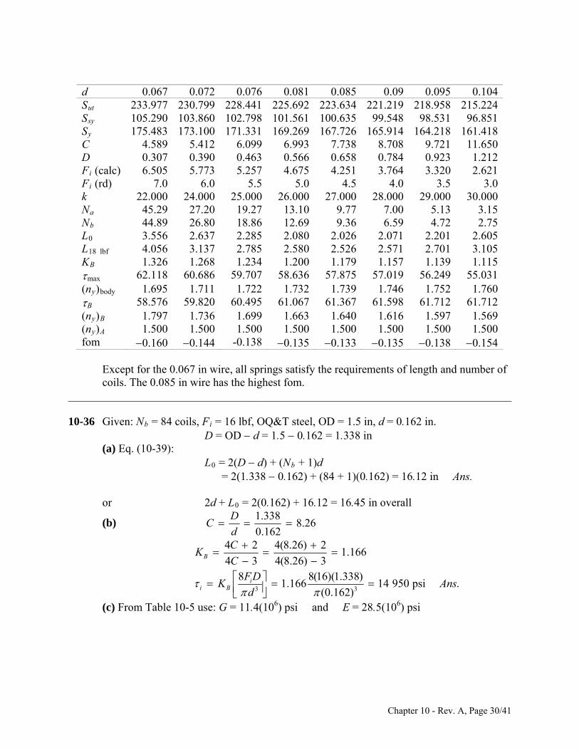
d 0.067 0.072 0.076 0.081 0.085 0.09 0.095 0.104Sut 233.977 230.799 228.441 225.692 223.634 221.219 218.958 215.224Ssy 105.290 103.860 102.798 101.561 100.635 99.548 98.531 96.851Sy 175.483 173.100 171.331 169.269 167.726 165.914 164.218 161.418C 4.589 5.412 6.099 6.993 7.738 8.708 9.721 11.650D 0.307 0.390 0.463 0.566 0.658 0.784 0.923 1.212Fi (calc) 6.505 5.773 5.257 4.675 4.251 3.764 3.320 2.621Fi (rd) 7.0 6.0 5.5 5.0 4.5 4.0 3.5 3.0k 22.000 24.000 25.000 26.000 27.000 28.000 29.000 30.000Na 45.29 27.20 19.27 13.10 9.77 7.00 5.13 3.15Nb 44.89 26.80 18.86 12.69 9.36 6.59 4.72 2.75L0 3.556 2.637 2.285 2.080 2.026 2.071 2.201 2.605L18 lbf 4.056 3.137 2.785 2.580 2.526 2.571 2.701 3.105KB 1.326 1.268 1.234 1.200 1.179 1.157 1.139 1.115max 62.118 60.686 59.707 58.636 57.875 57.019 56.249 55.031(ny)body 1.695 1.711 1.722 1.732 1.739 1.746 1.752 1.760B 58.576 59.820 60.495 61.067 61.367 61.598 61.712 61.712(ny)B 1.797 1.736 1.699 1.663 1.640 1.616 1.597 1.569(ny)A 1.500 1.500 1.500 1.500 1.500 1.500 1.500 1.500fom 0.160 0.144 -0.138 0.135 0.133 0.135 0.138 0.154
Except for the 0.067 in wire, all springs satisfy the requirements of length and number of
coils. The 0.085 in wire has the highest fom. ______________________________________________________________________________ 10-36 Given: Nb = 84 coils, Fi = 16 lbf, OQ&T steel, OD = 1.5 in, d = 0.162 in. D = OD d = 1.5 0.162 = 1.338 in (a) Eq. (10-39): L0 = 2(D d) + (Nb + 1)d = 2(1.338 0.162) + (84 + 1)(0.162) = 16.12 in Ans. or 2d + L0 = 2(0.162) + 16.12 = 16.45 in overall
1.3388.26
0.162
DC
d (b)
3 3
4 2 4(8.26) 21.166
4 3 4(8.26) 38 8(16)(1.338)
1.166 14 950 psi .(0.162)
B
ii B
CK
CF D
K Ansd
(c) From Table 10-5 use: G = 11.4(106) psi and E = 28.5(106) psi
Chapter 10 - Rev. A, Page 30/41

4 4 6
3 3
28.5(0.162) (11.4)(10 )
4.855 lb8 8(1.338) (84.4)a
Ed G
D N
11.484 84.4 turns
f/in .
a b
GN N
k Ans
(d) Table 10-4: A = 147 psi · inm , m = 0.187
0.187
147207.1 kpsi
(0.162)utS
0.75(207.1) 155.3 kpsi
0.50(207.1) 103.5 kpsiy
sy
S
S
Body
3
3 3(0.162) (103.5)(10 )
sy
B
d SF
K D
110.8 lbf8(1.166)(1.338)
Torsional stress on hook point B
22
2
2 2(0.25 0.162 / 2)4.086
0.1624 1 4(4.086) 1
( ) 1.243B
rC
dC
K2
3 3
4 4 4(4.086) 4
(0.162) (103.5)(10 )103.9 lbf
8(1.243)(1.338)
C
F
Normal stress on hook point A
11
2 21 1
1 1
2 1.3388.26
0.1624 1 4(8.26) 8.26 1
)4 ( 1) 4(8.26)(8.26 1)
16( ) 4
A
A
rC
dC C
KC C
K DS F
3 2
3
3 2
( 1.099
155.3(10 )85.8 lbf
16(1.099)(1.338) / (0.162) 4 / (0.162)
min(110.8, 103.9, 85.
yt d d
F
8) 85.8 lbf .Ans
(e) Eq. (10-48):
85.8 1614.4 in .
4.855iF F
y Ansk
______________________________________________________________________________
Chapter 10 - Rev. A, Page 31/41
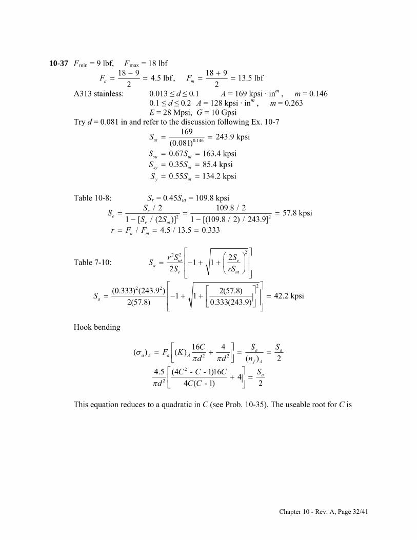
10-37 Fmin = 9 lbf, Fmax = 18 lbf
18 9 18 9
4.5 lbf , 13.5 lbf2 2a mF F
A313 stainless: 0.013 ≤ d ≤ 0.1 A = 169 kpsi · inm , m = 0.146 0.1 ≤ d ≤ 0.2 A = 128 kpsi · inm , m = 0.263 E = 28 Mpsi, G = 10 Gpsi Try d = 0.081 in and refer to the discussion following Ex. 10-7
0.146
169243.9 kpsi
(0.081)0.67 163.4 kpsi0.35 85.4 kpsi
ut
su ut
sy ut
S
S SS S
0.55 134.2 kpsiy utS S Table 10-8: Sr = 0.45Sut = 109.8 kpsi
2 2
/ 2 109.8 / 257.8 kpsi
1 [ / (2 )] 1 [(109.8 / 2) / 243.9]/ 4.5 / 13.5 0.333
re
r ut
S
S Sr F F
a m
S
2
2 2 21 1
2ut e
ae ut
r S SS
S rS
Table 7-10:
22 2(0.333) (243.9 ) 2(57.8)1 1 42.2 kpsi
2(57.8) 0.333(243.9)aS
Hook bending
2 2
2
2
16 4( ) ( )
( ) 2
4.5 (4 - - 1)164
4 ( - 1) 2
a aa A a A
f A
a
C S SF K
d d n
C C C S
d C C
This equation reduces to a quadratic in C (see Prob. 10-35). The useable root for C is
Chapter 10 - Rev. A, Page 32/41

22 2 2
22 3 2 3
2144 36
(0.081) (42.2)(10 ) (0.081) (42.2)(10 )
a a ad S d S
2 3
0.5144
(0.081) (42.2)(10 )0.5 2
144 144 36
4.91
d SC
3 3 33 5001000 4
8 8 exp(0.105 ) 6id d
D D C
0.398 in
3
.5i
D Cd
CF
Use the lowest Fi in the preferred range.
3(0.081) 33 500 4.91 31000 4
8(0.398) exp[0.105(4.91)] 6.58.55 lbf
iF
For simplicity we will round up to next 1/4 integer.
4 4 6
8.75 lbf18 9
36 lbf/in0.25
(0.081) (10)(10 )
iF
k
d G
3 3
0
max 0 max
23.7 turns8 8(36)(0.398)
1023.7 23.3 turns
28(2 1 ) [2(4.91) 1 23.3](0.081) 2.602 in
( ) / 2.602 (18 8.75) / 36 2.
a
b a
b
i
NkD
GN N
EL C N d
L L F F k
2
2
859 in
4.5(4) 4 1( ) 1
1a A
C C
d C
-3 2
2
18(10 ) 4(4.91 ) 4.91 11 21.1 kpsi
(0.081 ) 4.91 142.2
( ) 2 checks( ) 21.1
af A
a A
Sn
Body: 4 2 4(4.91) 2
1.3004 3 4(4.91) 3B
CK
C
Chapter 10 - Rev. A, Page 33/41

33
8(1.300)(4.5)(0.398)(10 ) 11.16 kpsi
(0.081)13.5
(11.16) 33.47 kpsi4.5
a
mm a
a
F
F
The repeating allowable stress from Table 7-8 is
Ssr = 0.30Sut = 0.30(243.9) = 73.17 kpsi The Gerber intercept is
2
73.17 / 238.5 kpsi
1 [(73.17 / 2) / 163.4]seS
From Table 6-7, 22
body
1 163.4 11.16 2(33.47)(38.5)( ) 1 1 2.53fn
2 33.47 38.5 163.4(11.16)
Let r2 = 2d = 2(0.081) = 0.162
22
2 4(4) 14, ( ) 1.25
4(4) 4( ) 1.25
( ) (11.16) 10.73 kpsi1.30
( ) 1.25( ) (33.47) 32.18 kpsi
1.30
B
Ba B a
B
Bm B m
B
rC K
dK
KK
K
Table 10-8: (Ssr )B = 0.28Sut = 0.28(243.9) = 68.3 kpsi
2
22
68.3 / 2( ) 35.7 kpsi
1 [(68.3 / 2) / 163.4]
1 163.4 10.73 2(32.18)(35.7)( ) 1 1 2.51
2 32.18 35.7 163.4(10.73)
se B
f B
S
n
Yield Bending:
2max
max 2
2-3
2
4 (4 1)( ) 1
1
4(18) 4(4.91) 4.91 11 (10 ) 84.4 kpsi
(0.081 ) 4.91 1134.2
( ) 1.5984.4
A
y A
F C C
d C
n
Body:
Chapter 10 - Rev. A, Page 34/41

body
( / ) (8.75 / 4.5)(11.16) 21.7 kpsi /( ) 11.16 / (33.47 21.7) 0.948
0.948( ) ( ) (85.4 21.7) 31.0 kpsi
1 0.948 1( ) 31.0
( ) 2.7811.16
i i a a
a m i
sa y sy i
sa yy
a
F Fr
rS S
rS
n
Hook shear: Hook shear:
max
0.3 0.3(243.9) 73.2 kpsi
( ) ( ) 10.73 32.18 42.9 kpsi73.2
( ) 1.7142.9
sy ut
a B m B
y B
S S
n
2 2 2 27.6 ( 2) 7.6 (0.081) (23.3 2)(0.398)fom 1.239
4 4bd N D
A tabulation of several wire sizes follow
d 0.081 0.085 0.092 0.098 0.105 0.12 Sut 243.920 242.210 239.427 237.229 234.851 230.317 Ssu 163.427 162.281 160.416 158.943 157.350 154.312 Sr 109.764 108.994 107.742 106.753 105.683 103.643 Se 57.809 57.403 56.744 56.223 55.659 54.585 Sa 42.136 41.841 41.360 40.980 40.570 39.786 C 4.903 5.484 6.547 7.510 8.693 11.451 D 0.397 0.466 0.602 0.736 0.913 1.374 OD 0.478 0.551 0.694 0.834 1.018 1.494 Fi (calc) 8.572 7.874 6.798 5.987 5.141 3.637 Fi (rd) 8.75 9.75 10.75 11.75 12.75 13.75 k 36.000 36.000 36.000 36.000 36.000 36.000 Na 23.86 17.90 11.38 8.03 5.55 2.77 Nb 23.50 17.54 11.02 7.68 5.19 2.42 L0 2.617 2.338 2.127 2.126 2.266 2.918 L18 lbf 2.874 2.567 2.328 2.300 2.412 3.036 (a)A 21.068 20.920 20.680 20.490 20.285 19.893 (nf)A 2.000 2.000 2.000 2.000 2.000 2.000 KB 1.301 1.264 1.216 1.185 1.157 1.117 (a)body 11.141 10.994 10.775 10.617 10.457 10.177 (m)body 33.424 32.982 32.326 31.852 31.372 30.532 Ssr 73.176 72.663 71.828 71.169 70.455 69.095 Sse 38.519 38.249 37.809 37.462 37.087 36.371 (nf)body 2.531 2.547 2.569 2.583 2.596 2.616 (K)B 1.250 1.250 1.250 1.250 1.250 1.250 (a)B 10.705 10.872 11.080 11.200 11.294 11.391 (m)B 32.114 32.615 33.240 33.601 33.883 34.173 (Ssr)B 68.298 67.819 67.040 66.424 65.758 64.489 (Sse)B 35.708 35.458 35.050 34.728 34.380 33.717
Chapter 10 - Rev. A, Page 35/41

(nf)B 2.519 2.463 2.388 2.341 2.298 2.235 Sy 134.156 133.215 131.685 130.476 129.168 126.674 (A)max 84.273 83.682 82.720 81.961 81.139 79.573 (ny)A 1.592 1.592 1.592 1.592 1.592 1.592 i 21.663 23.820 25.741 27.723 29.629 31.097 r 0.945 1.157 1.444 1.942 2.906 4.703 (Ssy)body 85.372 84.773 83.800 83.030 82.198 80.611 (Ssa)y 30.958 32.688 34.302 36.507 39.109 40.832 (ny)body 2.779 2.973 3.183 3.438 3.740 4.012 (Ssy)B 73.176 72.663 71.828 71.169 70.455 69.095 (B)max 42.819 43.486 44.321 44.801 45.177 45.564 (ny)B 1.709 1.671 1.621 1.589 1.560 1.516 fom 1.246 1.234 1.245 1.283 1.357 1.639
optimal fom The shaded areas show the conditions not satisfied. ______________________________________________________________________________ 10-38 For the hook, M = FR sin, ∂M/∂F = R sin
3/ 2 2
0
1sin
2
FRF R R d
EI EI
F
The total deflection of the body and the two hooks
3 3 3 3
4 4 4
3 3
4 4
8 8 ( / 2)2
2 ( / 64)( )
8 8
b b
ab
FD N FR FD N F D
d G EI d G E d
FD G FD NN
d G E d GG
N N
Q.E.D.a b E
______________________________________________________________________________ 10-39 Table 10-5 (d = 4 mm = 0.1575 in): E = 196.5 GPa Table 10-4 for A227: A = 1783 MPa · mmm, m = 0.190
Eq. (10-14): 0.190
17831370 MPa
4ut m
AS
d
Eq. (10-57): Sy = all = 0.78 Sut = 0.78(1370) = 1069 MPa
Chapter 10 - Rev. A, Page 36/41

D = OD d = 32 4 = 28 mm C = D/d = 28/4 = 7
Eq. (10-43):
22 4 7 7 14 11.119
4 ( 1) 4(7)(7 1)i
C CK
C C
Eq. (10-44): 3
32i
FrK
d
At yield, Fr = My , = Sy. Thus,
3 33 4 1069 10y
y
d S
6.00 N · m32 32(1.119)i
MK
Count the turns when M = 0
2.5 yMN
k4
10.8
d Ek
DN where from Eq. (10-51):
Thus,
4
2.5/ (10.8 )
yMN
d E DN
Solving for N gives
4
2.5
1 [10.8 / ( )]
2.5y
NDM d E
42.413 turns
1 10.8(28)(6.00) / 4 (196.5)
This means (2.5 - 2.413)(360) or 31.3 from closed. Ans. Treating the hand force as in the middle of the grip,
3
max
87.5112.5 87.5 68.75 mm
26.00 10
87.3 N .68.75
y
r
MF Ans
r
______________________________________________________________________________ 10-40 The spring material and condition are unknown. Given d = 0.081 in and OD = 0.500, (a) D = 0.500 0.081 = 0.419 in Using E = 28.6 Mpsi for an estimate
Chapter 10 - Rev. A, Page 37/41

4 4 6(0.081) (28.6)(10 )24.7 lbf · in/turn
10.8 10.8(0.419)(11)
d Ek
DN
for each spring. The moment corresponding to a force of 8 lbf
Fr = (8/2)(3.3125) = 13.25 lbf · in/spring
The fraction windup turn is
13.25ns
Frn
k 0.536 tur
24.7
The arm swings through an arc of slightly less than 180, say 165. This uses up 165/360 or 0.458 turns. So n = 0.536 0.458 = 0.078 turns are left (or 0.078(360) = 28.1 ). The original configuration of the spring was
Ans.
(b)
33 3
1.1684 1 4(5.17)(5.17 1)
32 32(13.25)1.168 297 10 psi 297 kpsi .
i
i
C C
MK A
2 2
0.4195.17
0.0814 1 4(5.17) 5.17 1
(0.081)
DC
dC C
K
nsd
To achieve this stress level, the spring had to have set removed. ______________________________________________________________________________ 10-41 (a) Consider half and double results
Straight section: M = 3FR, 3M
RP
Chapter 10 - Rev. A, Page 38/41

Upper 180 section:
[ (1 cos )]
s )
M F R R
(2 cos ), (2 coM
FR RF
Lower section: M = FR sin , sinM
R
F
Considering bending only:
/ 2 / 22 2 2 2
0
2 2
29 (2 cos ) ( sin )
2 9
4
2 19 9(19 18 )
4 2 2
lUFR dx FR R d F R R d
F EIF
R lEI
FR FRR l R l
EI EI
0 0
2 3 3
04 4sin
2 2R R
The spring rate is
2 (19
nsR R l
2.
18 )
F EIk A
(b) Given: A227 HD wire, d = 2 mm, R = 6 mm, and l = 25 mm. Table 10-5 (d = 2 mm = 0.0787 in): E = 197.2 MPa
310 N/m 10.65 N/mm .ns
9 4
2
2 197.2 10 0.002 / 6410.65
0.006 19 0.006 18 0.025k A
(c) The maximum stress will occur at the bottom of the top hook where the bending-
moment is 3FR and the axial fore is F. Using curved beam theory for bending,
Eq. (3-65), p. 119: 2
3
/ 4 / 2i i
ii
Mc FRc
Aer d e R d
Axial: F F
2 / 4a A d
Chapter 10 - Rev. A, Page 39/41

Combining, max 2
341
/ 2i
i a
RcFS
d e R d
y
2
(1) .3
4 1/ 2
y
i
d SF Ans
Rc
e R d
For the clip in part (b), Eq. (10-14) and Table 10-4: Sut = A/dm = 1783/20.190 = 1563 MPa Eq. (10-57): Sy = 0.78 Sut = 0.78(1563) = 1219 MPa Table 3-4, p. 121:
2
2 2
15.95804 mm
2 6 6 1nr
e = rc rn = 6 5.95804 = 0.04196 mm ci = rn (R d /2) = 5.95804 (6 2/2) = 0.95804 mm Eq. (1):
2 60.002 1219 1046.0 N .
3 6 0.958044 1
0.04196 6 1
F A
ns
______________________________________________________________________________ 10-42 (a)
Chapter 10 - Rev. A, Page 40/41

Chapter 10 - Rev. A, Page 41/41
/2 2
0 0
3 2 2
,
1 cos , 1 cos 0
1( ) 1 cos
4 3 2 4 2 3 812
l
F
MM Fx
F 0x x l
MM Fl FR l R l
F
Fx x dx F l R RdEI
Fl R l l R R
EI
The spring rate is
3 24 3 2F
2
12.
4 2 3 8
F EIns
l R l l R R
k A
(b) Given: A313 stainless wire, d = 0.063 in, R = 0.625 in, and l = 0.5 in. Table 10-5: E = 28 Mpsi
4 40.063 7.73364 64
I d 7 410 in
6 7
3 2 2
12 28 10 7.733 10
0.625k
4 0.5 3 0.625 2 0.5 4 2 0.5 0.625 3 8
36.3 lbf/in .Ans
(c) Table 10-4: A = 169 kpsiinm, m = 0.146 Eq. (10-14): Sut = A/ d m = 169/0.0630.146 = 253.0 kpsi Eq. (10-57): Sy = 0.61 Sut = 0.61(253.0) = 154.4 kpsi One can use curved beam theory as in the solution for Prob. 10-41. However, the
equations developed in Sec. 10-12 are equally valid. C = D/d = 2(0.625 + 0.063/2)/0.063 = 20.8
Eq. (10-43): 22 4 20.8 20.8 14 1
1.0374 1 4 20.8 20.8 1i
C C
C C
K
Eq. (10-44), setting = Sy:

Chapter 10 - Rev. A, Page 42/41
3
3 3
32 0.5 0.625321.037 154.4 10
0.063i y
FFrK S
d
Solving for F yields F = 3.25 lbf Ans. Try solving part (c) of this problem using curved beam theory. You should obtain the
same answer. ______________________________________________________________________________ 10-43 (a) M = Fx
2/ / / 6
M Fx Fx
I c I c bh
Constant stress,
2 6
(1) .6
Fx Fxh Ans
b
bh
At x = l,
6
/ .o o
Flh x l Ans
b
h h
(b) M = Fx, M / F = x
3/21/2
3/2 31 30 0 012
3/2 33/2
3 3
/ 1 12
/
2 12 8
3
l l l
oo
o o
M M F Fx x Fly dx dx x dx
EI E bh Ebh x l
Fl Fll
bh E bh E
3
3.
8obh EF
nsy l
k A
______________________________________________________________________________ 10-44 Computer programs will vary. ______________________________________________________________________________ 10-45 Computer programs will vary.


