
G

G G


1
0903
.GBImportant notes on transporting and mounting load lifting devicesto reach trucks
Transport
Depending on the overall height of the lifting mast and the local conditions transportcan be performed in three different ways
– Standing, with the lifting mast mounted (for trucks with low overall height)– Standing, with martially mounted lifting mast tilted towards the overhead guard (for
trucks with medium overall height). Hydraulic line for the lifting function is interrup-ted.
– Standing, with the lifting mast dismounted (for trucks with large overall height)
Safety Instructions for Assembly and Commissioning
f The assembly of the truck on site, commissioning the truck and instructing the drivermust be carried out by personnel trained and authorised by the manufacturer
Connect the hydraulic lines to the basic machine / mast interface and commission thetruck only after having installed the mast as per the instructions.

0903
.GB
2

NOTE
Z
to


ooo


1
0506
.GBAppendix
JH Traction Battery Operating Instructions
Z These operating instructions apply only to Jungheinrich battery models. If usinganother brand, refer to the manufacturer's operating instructions.

0506
.GB
2

NOTE

Zo

NOTE


t tt tt t
t to tt to to tt tt
t o


t tt tt tt t
t o

Z

o

to
o

o
o
o
Z
o
o
o

Z


e
a2
s
Q
h1
h6
h7
h8
m2
l2210
l7l1
x
c
l4 l
b5 b3 b4 b11 b1
a2
Ast
Wa
�
�h4
h3
h2
y
��
b2


XXXX kg
ETV 214
XXXX kg
GNE 160 740 DZ

Z
Z
Z

Z
Z
Z
Zo


o
o
oo
o
o


Z
Z

Z


Lifting the truck by crane
Requirements
Tools and Material Required
Procedure
The truck is now loaded.

Lifting the truck and cab by crane
Requirements
Tools and Material Required
Procedure
Zo o
The truck is now loaded.

Securing the industrial truck fortransport
Requirements
Procedure
The truck is now secured for transport.

Procedure
Z
Truck is operational.


Z o


NOTE


Exposing the battery
Requirements
Procedure
Z
Z
The battery is exposed.
U
T

Battery retracted
Requirements
Procedure
ZZ
The battery is now retracted.
U
T

Charge the battery
Requirements
Procedure
Battery is charged.

Procedure
The battery is charging.


Removing the battery
Requirements
Tools and Material Required
Procedure
Z
The battery is now removed.

Removing the battery with the battery trolley (o)
Requirements
Tools and Material Required
Procedure
o
The battery is now removed.
o

NOTE
Battery installation
Requirements
Tools and Material Required
Procedure
The battery is now assembled.

Installing the battery with the battery trolley (o)
Requirements
Tools and Material Required
Procedure
The battery is now assembled.
o


tt
t
o
o
t
o
t
tt
tt

o
o
oto
o
ooo
o
o

R
lbs mmkg
lbskg
mm
code inch inch


Setting the time
Procedure
The time is now set.
Changing time / residual time display mode
Procedure
The time / residual time indicator is shown.
Changing the time format
Procedure
Time display format changed.

Z
Z

Checking the truck before daily operation
Procedure
o
o
o

o
ZThe truck is now checked.

Entry and exit
Requirements
Procedure

Z
Z
Adjusting the driver's weight
NOTE
Procedure
The driver’s weight is now set.

Adjusting the backrest
Procedure
The backrest is now set.
Adjusting the seat position
Procedure
The seat position is now correctly set.
Z

Adjust the seat heating (o)
NOTE
Procedure
Seat heating set.
Z
o

o
Setting the driver's weight
NOTE
Procedure
Z
The driver’s weight is now set.
Fully automatic weight adjustment (o)
A compressor in the driver's seat adjusts the seat position according to the weight ofthe driver.
Adjusting the backrest
Procedure
The backrest is now set.
o
o

Adjusting the seat position
Procedure
The seat position is now correctly set.
Switching the seat heating on and off (o)
Procedure
Adjusting the lumbar vertebrae support
Procedure
The lumbar vertebrae support is now set.
o

Adjusting the steeringcolumn
Procedure
The steering column is nowpositioned.

o
NOTE
Z
Checking the seat belt
Procedure
Check the automatic locking system
Procedure
ZThe seat belt has now been checked.
Z
o

Putting on the seat belt
Procedure
The seat belt is now in place
Taking off the seat belt
Procedure
The seat belt is now removed.


o


Z
Switching on the truck
Requirements
Procedure
o
o
The truck is operational

Pressing the Emergency Disconnect switch
Procedure
Z
All electrical functions are deactivated. The truck brakes to a halt.
Releasing the Emergency Disconnect switch
Procedure
All electrical functions are enabled and the truck is operational again (assuming thetruck was not operational before the Emergency Disconnect was pressed).For CanCode and ISM the truck remains switched off.

Re-setting the emergency stop
Procedure
The emergency stop is reset.
Z

Z

Travel
Requirements
Procedure
Z
ZThe truck travels in the direction selected.


Braking with the reversing brake
Procedure
The truck decelerates until it starts to travel in the opposite direction.
Z

Braking with the coasting brake
Procedure
The truck decelerates.
Braking with the service brake
Procedure
The truck decelerates depending on thebrake pedal position.
Z

o
o
Setting the steering mode
Procedure
The steering mode is now set.
Steering
Procedure
The truck travels in the required direction.
o
o

Securing the forks
Procedure
Z
The forks are now secured.
ZZ

Z
Z
Z

Adjusting the forks
Requirements
Procedure
The forks are now adjusted.


Lifting and lowering with the SOLO-PILOT
Procedure
ZZ
The load unit is now raised or lowered.
Lifting and lowering with the MULTI-PILOT
Procedure
ZZ
The load unit is now raised or lowered.
H
S
H
S
U

o
Deactivating the speed reduction
Procedure
This deactivates the speed reduction and releases normal travel.
o

Moving the mast holder with theSOLO-PILOT
Procedure
The mast holder is now extended.
Moving the mast holder with theMULTI-PILOT
Procedure
The mast holder is now extended.
U
T
U
T

Tilting the mast / fork carriage with theSOLO-PILOT
Procedure
The mast / fork carriage is tilted.
Tilting the mast / fork carriage with theMULTI-PILOT
Procedure
The mast / fork carriage is tilted.
R
V
RV

Lifting load units
Requirements
Procedure
Load unit raised.

Transporting load units
Requirements
Procedure
NOTE
Depositing load units
Requirements
Procedure
Z
The load unit is lowered.

Z
Z


Z
Moving the sideshifter
Procedure
Z
The sideshifter is now moved.
X1
X2
Y1
Y2

Z
Moving the sideshifter
Procedure
Z
The sideshifter is now moved.
Y2X2
Y1X1

Connecting attachments hydraulically
Requirements
Procedure
The attachment is now hydraulically connected.
Z

Z
Mast emergency lowering
Requirements
Procedure
The mast is now lowered.

Parking the truck securely
Procedure
The truck is parked.


Preparing to move the truck without its own drive system
Procedure
Truck prepared.
Releasing the magnetic brake
Tools and Material Required
Procedure
The magnetic brake is now released.

Aligning the drive wheel
Procedure
Z
The drive wheel is now aligned.
Z

Towing the truck
Tools and Material Required

Procedure
The truck has now been towed.

Activating the magnetic brake
Tools and Material Required
Procedure
Magnetic brake is activated.

Z

o
o
o
o
o
o

o

Preparing the truck for operation by entering a valid user code
Procedure
The LED (148) lights up red.
When you enter a valid user code the LED (148) turns green.
Z
Switching off the truck
Procedure
The truck is switched off and the LED (148) is lit red.
Z
Z

Z
Requirements
Procedure
When you enter the valid master code the LED(148) flashes green.
The LEDs (144,148) flash green.
The LEDs (145,148) flash green.
ZThe LEDs (146,148) flash green.
Wait until the LED (148) flashes green. The setting is saved.
The truck is switched off and the LED (148) is lit red.
When you enter the valid master code the LED (148) flashes green.
The truck is switched off and the LED (148) is lit red.


Requirements
Procedure
When you enter the correct master code the LED(148) flashes green.
The LEDs (145,148) flash green.
Z
The LEDs (146,148) flash green.
Wait until the LED (148) flashes green. The setting is saved.
The truck is switched off and the LED (148) lights up red.
When you enter a valid user code the LED (148) turns green.
The truck is switched off and the LED (148) lights up red.


Requirements
Procedure
When you enter the correct master code the LED(148) flashes green.
The LEDs (144,148) flash green.
The LEDs (145,148) flash green.
Z
The LEDs (146,148) flash green.
Wait until the LED (148) flashes green. The setting is saved.
The truck is switched off and the LED (148) lights up red.
When you enter a valid user code the LED (148) turns green.
The truck is switched off and the LED (148) lights up red.


Requirements
Procedure
When you enter the valid master code the LED(148) flashes green.
The LEDs (145,148) flash green.
The LEDs (146,148) flash green.
Wait until the LED (148) flashes green. The user code is now deleted.
The truck is switched off and the LED (148) is lit red.
After entering the user code the LED (148) flashes red and the truck remainsswitched off.
The truck remains switched off and the LED (148) is lit red.


Requirements
Procedure
When you enter the valid master code the LED(148) flashes green.
The LEDs (146,148) flash green.
Wait until the LED (148) flashes green. All user codes are deleted.
The truck is switched off and the LED (148) is lit red.
After entering the user code the LED (148) flashes red and the truck remainsswitched off.
The truck remains switched off and the LED (148) is lit red.

Z
Requirements
Procedure
The length of the new master code is now changedand user codes have been added.

Requirements
Procedure
When you enter the correct master code the LED(148) flashes green.
Wait until the LED (148) flashes green.
Wait until the LED (148) flashes green. The setting is saved.
The truck is switched off and the LED (148) lights up red.
When you enter a valid user code the LED (148) turns green.
The truck is switched off and the LED (148) lights up red.

o
Z
o
Z
o
o

ZZ
Switching the work lights on and off
Procedure
The work lights are switched on / off.


Opening the service menu
Procedure
Opens the camera settings
Requirements
Procedure
Opens the system settings
Requirements
Procedure

Deactivates the keypad
Requirements
Procedure
Opens the user menu
Requirements
Procedure

Switching the beacon on and off
Procedure
The beacon is switched on / off.

Overriding the lift limit cutout withoutthe override button
Procedure
The lift limit cutout is now overridden.Lifting can now be performed at reducedspeed.
Overriding the lift limit cutout with the override button
Procedure
The lift limit cutout is now overridden.Lifting can now be performed at reduced speed.
H
S


Z

Z
Releasing hydraulic functions with the override button
Requirements
Procedure
The hydraulic functions are released for as long as the button is pressed.
Releasing hydraulic functions without the override button
Requirements
Procedure
Z
The hydraulic function is released.

Z
Z

Positioning the side shifter centrally
Requirements
Procedure
The side shifter is now centrally positioned.

Aligning the load handler horizontally
Procedure
The load handler is aligned horizontally.

kg

Weighing the load
Procedure
Z
The load is weighed and shown on the display.
kg

Z

Load backrest disassembly
Procedure
Load backrest assembly
Procedure
Z

Z
2
0001220

Setting the load centre of gravity
Procedure
Z
The load centre is set.


4,5 m
4 m / 157 in
/ 177 in


NOTE
Z

Z
Z


Z


NOTE

o


g cs b
a
1) A
G
E
Min. = 16lMax.= 29l ETM/V 214-216
B
2,9 l
E
2)
E
H
B +CJ
Max.= 34l ETM/V 318-325

Z

Procedure
oo

Raising and jacking up the truck securely
Requirements
Tools and Material Required
Procedure
Z
The truck is now securely raised and jacked up.

Z
Removing the seat panel
Procedure
The seat panel is now removed.
Removing the floor plate
Procedure
Floor plate removed.


Checking the hydraulic oil level
Requirements
Procedure
Z
The hydraulic oil level is now checked.


Removing the safety cover
Procedure
Safety cover removed.
Removing the instrument panel cover
Procedure
Z
Instrument panel cover removed.
Checking electrical fuses
Requirements
Procedure
The electrical fuses are now checked.


Checking the wheel attachment
Requirements
Tools and Material Required
Procedure
ZThe wheel attachment is now checked.

Z

Procedure
Z
NOTE
Z

Procedure


Z
Z

NOTE
Z
t
k

t
t
t
t
t
t
t
t
tt
t
ttt

kkkt
t
t
t
kt
t
t

t

tttt
t
t
ttttt
t
tt
t
t
t
ttt
t
k t
t
t

tttttttt
t
t
t
t
t
t
t
t
t
t
t
t
t
k tt
t
tt
tt

ttttt
t
tt
t
tt
t
t
ttttt
tt

t
t
t
t
t
ttt
t
t
tttt
tt
t
ttt
t
t
ttt
t
t
t
t
t
t

t
tt
ttt
t
t
t
t
t

tt
t
t
t
t
t
t
t

t
t
t
t
t
t
t

t
t
t
t
t
t
t
t
tt
t
ttt

kkkt
t
t
t
kt
t
t

t

tttt
t
t
ttttt
t
tt
t
t
t
ttt
t
k t
t
t

tttttttt
t
t
t
t
t
t
t
t
t
t
t
t
t
k tt
t
tt
tt

ttttt
t
tt
t
tt
t
t
ttttt
tt

t
t
t
t
t
ttt
t
t
tttt
tt
t
ttt

t
t
ttt
t
t
t
t
t
t

t
tt
ttt
t
t
t
t
t

tt
t
t
t
t
t
t
t

t
t
t
t
t
t
t


NOTE
Z
to


Z


Z
Checks and operations to be performed before starting daily work
Procedure
Z
The test is now complete.

Z
NOTE
Z
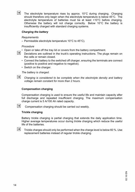
Charging the battery
Requirements
Procedure
Z
The battery is charged.
Z Charging is considered to be complete when the electrolyte density and batteryvoltage remain constant for more than 2 hours.
Z
Z

Z
Z

Z
Z

Z

Checks and operations to be performed before starting daily work
Procedure
The test is now complete.
Z
Z

NOTE

Charging the battery
Requirements
Procedure
Z
The battery is charged.
Z Charging is considered to be complete when the electrolyte density and batteryvoltage remain constant for more than 2 hours.
Z
Z
Z

Z
Z
Z
Z


Z


NOTE


Cleaning the battery with a high pressure cleaner
Requirements
Procedure
Z
Z
Battery cleaned.

NOTE
Z


